1
APEX
DIGITAL AUDIO ROUTER
Installation and Service Manual
Standard Software Version: 3.0 Apex Plus Software Release: 2.0
071825704
NOVEMBER 2009
Affiliate with the N.V. KEMA in The Netherlands
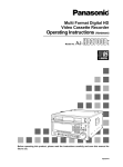
CERTIFICATE
Certificate Number: 510040.001
The Quality System of:
Thomson Inc, and it’s wordwide Grass Valley division affiliates DBA
GRASS VALLEY
Headquarters
400 Providence Mine Rd
Nevada City, CA 95959
United States
15655 SW Greystone Ct.
Beaverton, OR 97006
United States
10 Presidential Way
Suite 300
Woburn, MA 01801
United States
Kapittelweg 10
4827 HG Breda
The Nederlands
7140 Baymeadows Way
Ste 101
Jacksonville, FL 32256
United States
2300 So. Decker Lake Blvd.
Salt Lake City, UT 84119
United States
Rue du Clos Courtel
CS 31719
35517 Cesson-Sevigné Cedex
France
1 rue de l’Hautil
Z.I. des Boutries BP 150
78702 Conflans-Sainte
Honorine Cedex
France
Technopole Brest-Iroise
Site de la Pointe du Diable
CS 73808
29238 Brest Cedex 3
France
40 Rue de Bray
2 Rue des Landelles
35510 Cesson Sevigné
France
Spinnereistrasse 5
CH-5300 Turgi
Switzerland
Brunnenweg 9
D-64331 Weiterstadt
Germany
Carl-Benz-Strasse 6-8
67105 Schifferstadt
Germany
Including its implementation, meets the requirements of the standard:
ISO 9001:2008
Scope:
The design, manufacture and support of video and audio hardware and software products and
related systems.
This Certificate is valid until:
This Certificate is valid as of:
Certified for the first time:
June 14, 2012
June 14, 2009
June 14, 2000
H. Pierre Sallé
President
KEMA-Registered Quality
The method of operation for quality certification is defined in the KEMA General Terms
And Conditions For Quality And Environmental Management Systems Certifications.
Integral publication of this certificate is allowed.
KEMA-Registered Quality, Inc.
4377 County Line Road
Chalfont, PA 18914
Ph: (215)997-4519
Fax: (215)997-3809
CRT 001 073004
Accredited By:
ANAB
APEX
DIGITAL AUDIO ROUTER
Installation and Service Manual
Standard Software Version: 3.0 Apex Plus Software Release: 2.0
071825704
NOVEMBER 2009
Contacting Grass Valley
International
France
United States/Canada
+800 8080 2020 or +33 1 48 25 20 20
24 x 7
Support Centers 24 x 7
Asia
+1 800 547 8949 or +1 530 478 4148
Hong Kong, Taiwan, Korea, Macau: +852 2531 3058 Indian Subcontinent: +91 22 24933476
Southeast Asia/Malaysia: +603 7805 3884 Southeast Asia/Singapore: +65 6379 1313
China: +861 0660 159 450 Japan: +81 3 5484 6868
Local Support
Australia and New Zealand: +61 1300 721 495
Central/South America: +55 11 5509 3443
Centers
(available
Middle East: +971 4 299 64 40 Near East and Africa: +800 8080 2020 or +33 1 48 25 20 20
during normal
Belarus, Russia, Tadzikistan, Ukraine, Uzbekistan: +7 095 2580924 225 Switzerland: +41 1 487 80 02
business hours)
S. Europe/Italy-Roma: +39 06 87 20 35 28 -Milan: +39 02 48 41 46 58 S. Europe/Spain: +34 91 512 03 50
Europe
Benelux/Belgium: +32 (0) 2 334 90 30 Benelux/Netherlands: +31 (0) 35 62 38 42 1 N. Europe: +45 45 96 88 70
Germany, Austria, Eastern Europe: +49 6150 104 444 UK, Ireland, Israel: +44 118 923 0499
Copyright © Grass Valley, Inc. All rights reserved.
This product may be covered by one or more U.S. and foreign patents.
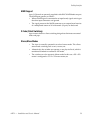
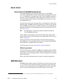
Grass Valley Web Site
The www.grassvalley.com web site offers the following:
Online User Documentation — Current versions of product catalogs, brochures,
data sheets, ordering guides, planning guides, manuals, and release notes
in .pdf format can be downloaded.
FAQ Database — Solutions to problems and troubleshooting efforts can be
found by searching our Frequently Asked Questions (FAQ) database.
Software Downloads — Download software updates, drivers, and patches.
6
APEX — Installation and Service Manual
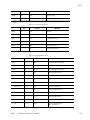
Contents
Contents
Preface
About This Manual . . . . . . . . . . . . . . . . . . . . . . . . . . . . . . . . . . . . . . . . . . . . . . . . . . . . 11
Additional Documentation . . . . . . . . . . . . . . . . . . . . . . . . . . . . . . . . . . . . . . . . . . . 11
Safety Summary
Safety Terms and Symbols. . . . . . . . . . . . . . . . . . . . . . . . . . . . . . . . . . . . . . . . . . . . . .
Terms in This Manual . . . . . . . . . . . . . . . . . . . . . . . . . . . . . . . . . . . . . . . . . . . . . . . .
Terms on the Product . . . . . . . . . . . . . . . . . . . . . . . . . . . . . . . . . . . . . . . . . . . . . . . .
Symbols on the Product . . . . . . . . . . . . . . . . . . . . . . . . . . . . . . . . . . . . . . . . . . . . . .
Warnings . . . . . . . . . . . . . . . . . . . . . . . . . . . . . . . . . . . . . . . . . . . . . . . . . . . . . . . . . . . .
Cautions . . . . . . . . . . . . . . . . . . . . . . . . . . . . . . . . . . . . . . . . . . . . . . . . . . . . . . . . . . . . .
13
13
13
14
14
15
Regulatory Notices
Certifications and Compliances . . . . . . . . . . . . . . . . . . . . . . . . . . . . . . . . . . . . . . . . .
FCC Emission Control . . . . . . . . . . . . . . . . . . . . . . . . . . . . . . . . . . . . . . . . . . . . . . .
Canadian EMC Notice of Compliance . . . . . . . . . . . . . . . . . . . . . . . . . . . . . . . . . .
EN 55103 Class A Warning . . . . . . . . . . . . . . . . . . . . . . . . . . . . . . . . . . . . . . . . . . .
Canadian Certified Power Cords . . . . . . . . . . . . . . . . . . . . . . . . . . . . . . . . . . . . . .
Canadian Certified AC Adapter . . . . . . . . . . . . . . . . . . . . . . . . . . . . . . . . . . . . . . .
Laser Compliance . . . . . . . . . . . . . . . . . . . . . . . . . . . . . . . . . . . . . . . . . . . . . . . . . . .
Laser Safety Requirements . . . . . . . . . . . . . . . . . . . . . . . . . . . . . . . . . . . . . . . . . .
Laser Safety . . . . . . . . . . . . . . . . . . . . . . . . . . . . . . . . . . . . . . . . . . . . . . . . . . . . . . .
FCC Emission Limits . . . . . . . . . . . . . . . . . . . . . . . . . . . . . . . . . . . . . . . . . . . . . . .
Certifications: . . . . . . . . . . . . . . . . . . . . . . . . . . . . . . . . . . . . . . . . . . . . . . . . . . . . . . .
25
25
25
25
26
26
26
26
26
27
27
Section 1 — Introduction
Apex Features . . . . . . . . . . . . . . . . . . . . . . . . . . . . . . . . . . . . . . . . . . . . . . . . . . . . . . . . 29
Section 2 — Planning Guide
Principal Components . . . . . . . . . . . . . . . . . . . . . . . . . . . . . . . . . . . . . . . . . . . . . . . . .
Space and Ventilation Requirements . . . . . . . . . . . . . . . . . . . . . . . . . . . . . . . . . . . . .
Expanded (Multi-Chassis) Systems . . . . . . . . . . . . . . . . . . . . . . . . . . . . . . . . . . . . . .
Standard Apex Models . . . . . . . . . . . . . . . . . . . . . . . . . . . . . . . . . . . . . . . . . . . . . . .
Apex Plus Models . . . . . . . . . . . . . . . . . . . . . . . . . . . . . . . . . . . . . . . . . . . . . . . . . . .
Notes . . . . . . . . . . . . . . . . . . . . . . . . . . . . . . . . . . . . . . . . . . . . . . . . . . . . . . . . . . . .
Fiber Extenders (Standard Apex Only) . . . . . . . . . . . . . . . . . . . . . . . . . . . . . . . . .
Facility Interface . . . . . . . . . . . . . . . . . . . . . . . . . . . . . . . . . . . . . . . . . . . . . . . . . . . . . .
Audio Signals . . . . . . . . . . . . . . . . . . . . . . . . . . . . . . . . . . . . . . . . . . . . . . . . . . . . . . .
Reference Connections . . . . . . . . . . . . . . . . . . . . . . . . . . . . . . . . . . . . . . . . . . . . .
MADI Support . . . . . . . . . . . . . . . . . . . . . . . . . . . . . . . . . . . . . . . . . . . . . . . . . . . .
V-Fade (Silent Switching) . . . . . . . . . . . . . . . . . . . . . . . . . . . . . . . . . . . . . . . . . . .
Stereo/Mono Modes . . . . . . . . . . . . . . . . . . . . . . . . . . . . . . . . . . . . . . . . . . . . . . .
Output Monitoring . . . . . . . . . . . . . . . . . . . . . . . . . . . . . . . . . . . . . . . . . . . . . . . .
APEX Installation and Service Manual
31
32
36
36
36
37
45
47
47
48
53
53
53
54
7
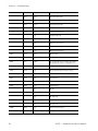
Contents
Multi-frame Systems. . . . . . . . . . . . . . . . . . . . . . . . . . . . . . . . . . . . . . . . . . . . . . .
Redundancy . . . . . . . . . . . . . . . . . . . . . . . . . . . . . . . . . . . . . . . . . . . . . . . . . . . . . . . . .
Control Board . . . . . . . . . . . . . . . . . . . . . . . . . . . . . . . . . . . . . . . . . . . . . . . . . . . . . .
Matrix Board . . . . . . . . . . . . . . . . . . . . . . . . . . . . . . . . . . . . . . . . . . . . . . . . . . . . . . .
Power Supply . . . . . . . . . . . . . . . . . . . . . . . . . . . . . . . . . . . . . . . . . . . . . . . . . . . . . .
Control Systems . . . . . . . . . . . . . . . . . . . . . . . . . . . . . . . . . . . . . . . . . . . . . . . . . . . . . .
Jupiter Facility Control System. . . . . . . . . . . . . . . . . . . . . . . . . . . . . . . . . . . . . . . .
CC-2010 Matrix (Crosspoint Bus) Cable . . . . . . . . . . . . . . . . . . . . . . . . . . . . . .
Jupiter Control System Planning . . . . . . . . . . . . . . . . . . . . . . . . . . . . . . . . . . . .
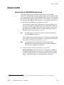
Encore Control . . . . . . . . . . . . . . . . . . . . . . . . . . . . . . . . . . . . . . . . . . . . . . . . . . . . .
Encore Control via NR-33000 Broadlinx Board . . . . . . . . . . . . . . . . . . . . . . . .
SMS7000 Control. . . . . . . . . . . . . . . . . . . . . . . . . . . . . . . . . . . . . . . . . . . . . . . . . . . .
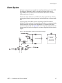
Alarm System . . . . . . . . . . . . . . . . . . . . . . . . . . . . . . . . . . . . . . . . . . . . . . . . . . . . . . . .
Specifications. . . . . . . . . . . . . . . . . . . . . . . . . . . . . . . . . . . . . . . . . . . . . . . . . . . . . . . . .
75 Ohm Version. . . . . . . . . . . . . . . . . . . . . . . . . . . . . . . . . . . . . . . . . . . . . . . . . . .
110 Ohm Version . . . . . . . . . . . . . . . . . . . . . . . . . . . . . . . . . . . . . . . . . . . . . . . . . .
MADI . . . . . . . . . . . . . . . . . . . . . . . . . . . . . . . . . . . . . . . . . . . . . . . . . . . . . . . . . . .
Environmental . . . . . . . . . . . . . . . . . . . . . . . . . . . . . . . . . . . . . . . . . . . . . . . . . . . .
Physical . . . . . . . . . . . . . . . . . . . . . . . . . . . . . . . . . . . . . . . . . . . . . . . . . . . . . . . . . .
Alarm . . . . . . . . . . . . . . . . . . . . . . . . . . . . . . . . . . . . . . . . . . . . . . . . . . . . . . . . . . .
AC Power Input . . . . . . . . . . . . . . . . . . . . . . . . . . . . . . . . . . . . . . . . . . . . . . . . . .
Fiber Extenders . . . . . . . . . . . . . . . . . . . . . . . . . . . . . . . . . . . . . . . . . . . . . . . . . . . . .
APX-FBR-EXT . . . . . . . . . . . . . . . . . . . . . . . . . . . . . . . . . . . . . . . . . . . . . . . . . . . .
APX-SFP-M300 . . . . . . . . . . . . . . . . . . . . . . . . . . . . . . . . . . . . . . . . . . . . . . . . . . .
APX-SFP-S5000 . . . . . . . . . . . . . . . . . . . . . . . . . . . . . . . . . . . . . . . . . . . . . . . . . . .
Fiber Optic Cable Pair . . . . . . . . . . . . . . . . . . . . . . . . . . . . . . . . . . . . . . . . . . . . .
Ordering Information . . . . . . . . . . . . . . . . . . . . . . . . . . . . . . . . . . . . . . . . . . . . . . . . .
Control Board . . . . . . . . . . . . . . . . . . . . . . . . . . . . . . . . . . . . . . . . . . . . . . . . . . . . . .
APX-CX-34000 . . . . . . . . . . . . . . . . . . . . . . . . . . . . . . . . . . . . . . . . . . . . . . . . . . . .
Frames, Fans and Power Supplies . . . . . . . . . . . . . . . . . . . . . . . . . . . . . . . . . . . . .
APX-FRM-34075 . . . . . . . . . . . . . . . . . . . . . . . . . . . . . . . . . . . . . . . . . . . . . . . . . .
APX-FRM-34110 . . . . . . . . . . . . . . . . . . . . . . . . . . . . . . . . . . . . . . . . . . . . . . . . . .
APX-35075-IN . . . . . . . . . . . . . . . . . . . . . . . . . . . . . . . . . . . . . . . . . . . . . . . . . . . .
APX-35075-OUT . . . . . . . . . . . . . . . . . . . . . . . . . . . . . . . . . . . . . . . . . . . . . . . . . .
APX-35110-IN . . . . . . . . . . . . . . . . . . . . . . . . . . . . . . . . . . . . . . . . . . . . . . . . . . . .
APX-35110-OUT . . . . . . . . . . . . . . . . . . . . . . . . . . . . . . . . . . . . . . . . . . . . . . . . . .
APX-PS-34000 . . . . . . . . . . . . . . . . . . . . . . . . . . . . . . . . . . . . . . . . . . . . . . . . . . . .
APX-FM-34000. . . . . . . . . . . . . . . . . . . . . . . . . . . . . . . . . . . . . . . . . . . . . . . . . . . .
I/O Boards . . . . . . . . . . . . . . . . . . . . . . . . . . . . . . . . . . . . . . . . . . . . . . . . . . . . . . . . .
APX-IN-34075 . . . . . . . . . . . . . . . . . . . . . . . . . . . . . . . . . . . . . . . . . . . . . . . . . . . .
APX-IN-34110 . . . . . . . . . . . . . . . . . . . . . . . . . . . . . . . . . . . . . . . . . . . . . . . . . . . .
APX-OP-34075 . . . . . . . . . . . . . . . . . . . . . . . . . . . . . . . . . . . . . . . . . . . . . . . . . . . .
APX-OP-34110 . . . . . . . . . . . . . . . . . . . . . . . . . . . . . . . . . . . . . . . . . . . . . . . . . . . .
Matrix Boards . . . . . . . . . . . . . . . . . . . . . . . . . . . . . . . . . . . . . . . . . . . . . . . . . . . . . .
APX-MX-34000A . . . . . . . . . . . . . . . . . . . . . . . . . . . . . . . . . . . . . . . . . . . . . . . . . .
License (Configuration) Boards . . . . . . . . . . . . . . . . . . . . . . . . . . . . . . . . . . . . . . .
APX-CL-34075 . . . . . . . . . . . . . . . . . . . . . . . . . . . . . . . . . . . . . . . . . . . . . . . . . . . .
APX-CL-34110 . . . . . . . . . . . . . . . . . . . . . . . . . . . . . . . . . . . . . . . . . . . . . . . . . . . .
APX-CL-35075-IN . . . . . . . . . . . . . . . . . . . . . . . . . . . . . . . . . . . . . . . . . . . . . . . . .
APX-CL-35110-IN . . . . . . . . . . . . . . . . . . . . . . . . . . . . . . . . . . . . . . . . . . . . . . . . .
APX-CL-35075-OUT . . . . . . . . . . . . . . . . . . . . . . . . . . . . . . . . . . . . . . . . . . . . . . .
APX-CL-35110-OUT . . . . . . . . . . . . . . . . . . . . . . . . . . . . . . . . . . . . . . . . . . . . . . .
InfiniBand Cables . . . . . . . . . . . . . . . . . . . . . . . . . . . . . . . . . . . . . . . . . . . . . . . . . . .
APX-INFI-CABL . . . . . . . . . . . . . . . . . . . . . . . . . . . . . . . . . . . . . . . . . . . . . . . . . .
8
55
56
56
56
56
57
57
58
58
59
59
59
61
62
62
62
62
63
63
63
63
63
63
64
64
64
65
65
65
65
65
65
65
66
66
66
66
66
66
66
66
67
67
67
67
67
67
67
67
67
67
67
68
68
APEX Installation and Service Manual
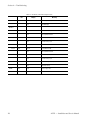
Contents
Master Clock Cables . . . . . . . . . . . . . . . . . . . . . . . . . . . . . . . . . . . . . . . . . . . . . . . . .
Crosspoint Bus Items . . . . . . . . . . . . . . . . . . . . . . . . . . . . . . . . . . . . . . . . . . . . . . . .
MNC-XPT-CBL-3 . . . . . . . . . . . . . . . . . . . . . . . . . . . . . . . . . . . . . . . . . . . . . . . . . .
MNC-XPT-CBL-10 . . . . . . . . . . . . . . . . . . . . . . . . . . . . . . . . . . . . . . . . . . . . . . . . .
MNC-XPT-CBL-25 . . . . . . . . . . . . . . . . . . . . . . . . . . . . . . . . . . . . . . . . . . . . . . . . .
MNC-XPT-CBL-50 . . . . . . . . . . . . . . . . . . . . . . . . . . . . . . . . . . . . . . . . . . . . . . . . .
Crosspoint Bus Terminator . . . . . . . . . . . . . . . . . . . . . . . . . . . . . . . . . . . . . . . . .
Miscellaneous. . . . . . . . . . . . . . . . . . . . . . . . . . . . . . . . . . . . . . . . . . . . . . . . . . . . . . .
Spare Parts Kits . . . . . . . . . . . . . . . . . . . . . . . . . . . . . . . . . . . . . . . . . . . . . . . . . . .
68
69
69
69
69
69
69
69
69
Section 3 — Installation
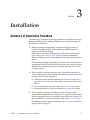
Summary of Installation Procedure . . . . . . . . . . . . . . . . . . . . . . . . . . . . . . . . . . . . . . 71
Expanded (Multi-Chassis) Systems . . . . . . . . . . . . . . . . . . . . . . . . . . . . . . . . . . . . . . 79
Standard Apex Models . . . . . . . . . . . . . . . . . . . . . . . . . . . . . . . . . . . . . . . . . . . . . . . 79
Apex Plus Models . . . . . . . . . . . . . . . . . . . . . . . . . . . . . . . . . . . . . . . . . . . . . . . . . . . 79
Installation . . . . . . . . . . . . . . . . . . . . . . . . . . . . . . . . . . . . . . . . . . . . . . . . . . . . . . . 83
Fiber Extenders (Standard Apex Only) . . . . . . . . . . . . . . . . . . . . . . . . . . . . . . . . . 85
Power Supply Notes . . . . . . . . . . . . . . . . . . . . . . . . . . . . . . . . . . . . . . . . . . . . . . . . . . . 88
Reference Connections . . . . . . . . . . . . . . . . . . . . . . . . . . . . . . . . . . . . . . . . . . . . . . . . . 89
Single Video Reference . . . . . . . . . . . . . . . . . . . . . . . . . . . . . . . . . . . . . . . . . . . . . . . 90
Single AES Reference . . . . . . . . . . . . . . . . . . . . . . . . . . . . . . . . . . . . . . . . . . . . . . . . 91
Single Video Reference – Redundant Operation . . . . . . . . . . . . . . . . . . . . . . . . . 92
Dual References - Redundant Operation . . . . . . . . . . . . . . . . . . . . . . . . . . . . . . . . 93
CX-34000 Control Crosspoint Board Configuration . . . . . . . . . . . . . . . . . . . . . . . . 94
S34-1/2 – Stereo/Mono Mode Selection. . . . . . . . . . . . . . . . . . . . . . . . . . . . . . . 94
S34-8 – Enable Reference/V-fade Master Setting . . . . . . . . . . . . . . . . . . . . . . . 94
S28 5-8 Reference/V-fade Settings . . . . . . . . . . . . . . . . . . . . . . . . . . . . . . . . . . . 95
Output Card Switches . . . . . . . . . . . . . . . . . . . . . . . . . . . . . . . . . . . . . . . . . . . . . . 96
Input Card Switches . . . . . . . . . . . . . . . . . . . . . . . . . . . . . . . . . . . . . . . . . . . . . . . 96
S31 (LIN NUM / VREF) . . . . . . . . . . . . . . . . . . . . . . . . . . . . . . . . . . . . . . . . . . . . 96
S32 (SR AREF/VREF) . . . . . . . . . . . . . . . . . . . . . . . . . . . . . . . . . . . . . . . . . . . . . . 96
AES / Video Reference Selections . . . . . . . . . . . . . . . . . . . . . . . . . . . . . . . . . . . . 96
V-fade (Silent Switching) . . . . . . . . . . . . . . . . . . . . . . . . . . . . . . . . . . . . . . . . . . . 97
Output Monitoring . . . . . . . . . . . . . . . . . . . . . . . . . . . . . . . . . . . . . . . . . . . . . . . . . . . . 99
Multi-frame Systems . . . . . . . . . . . . . . . . . . . . . . . . . . . . . . . . . . . . . . . . . . . . . . 100
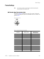
Frame Settings . . . . . . . . . . . . . . . . . . . . . . . . . . . . . . . . . . . . . . . . . . . . . . . . . . . . . . . 101
SW1 Switch (Apex Plus Systems Only) . . . . . . . . . . . . . . . . . . . . . . . . . . . . . . . . 101
Max Size Switch . . . . . . . . . . . . . . . . . . . . . . . . . . . . . . . . . . . . . . . . . . . . . . . . . . . . 102
Frame Number Switch . . . . . . . . . . . . . . . . . . . . . . . . . . . . . . . . . . . . . . . . . . . . . . 103
Jupiter Control . . . . . . . . . . . . . . . . . . . . . . . . . . . . . . . . . . . . . . . . . . . . . . . . . . . . . . . 104
Encore Control. . . . . . . . . . . . . . . . . . . . . . . . . . . . . . . . . . . . . . . . . . . . . . . . . . . . . . . 109
Encore Control via NR-33000 Broadlinx board . . . . . . . . . . . . . . . . . . . . . . . . 109
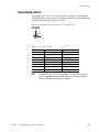
Section 4 — Troubleshooting
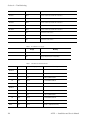
LEDs . . . . . . . . . . . . . . . . . . . . . . . . . . . . . . . . . . . . . . . . . . . . . . . . . . . . . . . . . . . . . . . 113
Reset Procedures . . . . . . . . . . . . . . . . . . . . . . . . . . . . . . . . . . . . . . . . . . . . . . . . . . . . . 119
APEX Installation and Service Manual
9
Contents
10
Glossary . . . . . . . . . . . . . . . . . . . . . . . . . . . . . . . . . . . . . . . . . . . . . . . . . . . . . . . . . . . . . . . . .
121
Index . . . . . . . . . . . . . . . . . . . . . . . . . . . . . . . . . . . . . . . . . . . . . . . . . . . . . . . . . . . . . . . . . . . . .
131
APEX Installation and Service Manual
Preface
About This Manual
This manual provides system planning, installation and troubleshooting
information specific to the Apex Digital Audio Router.
The Apex Digital Audio Router can be controlled by the Grass Valley
Jupiter or Encore control systems. Configuration information for the
control system itself is contained in the control system’s documentation set:
Jupiter Control System Release Notes series, 0718275xx.
Jupiter VM-3000 Installation and Operating Manual, 0718305xx.
Jupiter CM-4000 Installation and Operating Manual, 0718261xx.
Jupiter Getting Started Guide, 04-045707-003.
Encore Control System Release Notes series, 0718153xx.
Encore Installation and Service Manual, 0718103xx.
Encore Control System User Manual, 0718104xx.
Encore Control Panels Manual, 0718053xx
An electronic copy of the documentation set is normally provided with the
system on CD-ROM 0718130xx. The CD Includes SMS7000 Series Control
System, Acappella, Concerto, Encore, Jupiter, JEP 100, Prelude, and Trinix
documentation.
Individual printed manuals may be ordered by contacting Technical Support. They are also available on our web site. See Contacting Grass Valley.
Additional Documentation
CD-ROM 071827407 includes legacy Jupiter, Saturn, Triton, and Venus
manuals.
APEX Installation and Service Manual
11
Preface
12
APEX Installation and Service Manual
Safety Summary
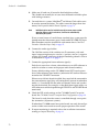
Read and follow the important safety information below, noting especially
those instructions related to risk of fire, electric shock or injury to persons.
Additional specific warnings not listed here may be found throughout the
manual.
WARNING Any instructions in this manual that require opening the equipment cover
or enclosure are for use by qualified service personnel only. To reduce the
risk of electric shock, do not perform any servicing other than that contained in the operating instructions unless you are qualified to do so.
Safety Terms and Symbols
Terms in This Manual
Safety-related statements may appear in this manual in the following form:
WARNING Warning statements identify conditions or practices that may result in personal injury or loss of life.
CAUTION Caution statements identify conditions or practices that may result in damage
to equipment or other property, or which may cause equipment crucial to
your business environment to become temporarily non-operational.
Terms on the Product
The following terms may appear on the product:
DANGER — A personal injury hazard is immediately accessible as you read
the marking.
WARNING — A personal injury hazard exists but is not immediately acces-
sible as you read the marking.
CAUTION — A hazard to property, product, and other equipment is present.
APEX — Installation and Service Manual
13
Safety Summary
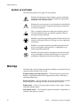
Symbols on the Product
The following symbols may appear on the product:
Indicates that dangerous high voltage is present within the
equipment enclosure that may be of sufficient magnitude to
constitute a risk of electric shock.
Indicates that user, operator or service technician should refer
to product manual(s) for important operating, maintenance,
or service instructions.
This is a prompt to note fuse rating when replacing fuse(s).
The fuse referenced in the text must be replaced with one
having the ratings indicated.
Identifies a protective grounding terminal which must be connected to earth ground prior to making any other equipment
connections.
Identifies an external protective grounding terminal which
may be connected to earth ground as a supplement to an
internal grounding terminal.
Indicates that static sensitive components are present which
may be damaged by electrostatic discharge. Use anti-static
procedures, equipment and surfaces during servicing.
Warnings
The following warning statements identify conditions or practices that can
result in personal injury or loss of life:
Dangerous voltage or current may be present — Disconnect power and remove
battery (if applicable) before removing protective panels, soldering, or
replacing components.
Do not service alone — Do not internally service this product unless another
person capable of rendering first aid and resuscitation is present.
Remove jewelry — Prior to servicing, remove jewelry such as rings, watches,
and other metallic objects.
Avoid exposed circuitry — Do not touch exposed connections, components or
circuitry when power is present.
14
APEX — Installation and Service Manual
Safety Summary
Use proper power cord — Use only the power cord supplied or specified for
this product.
Ground product — Connect the grounding conductor of the power cord to
earth ground.
Operate only with covers and enclosure panels in place — Do not operate this
product when covers or enclosure panels are removed.
Use correct fuse — Use only the fuse type and rating specified for this
product.
Use only in dry environment — Do not operate in wet or damp conditions.
Use only in non-explosive environment — Do not operate this product in an
explosive atmosphere.
High leakage current may be present — Earth connection of product is essential
before connecting power.
Dual power supplies may be present — Be certain to plug each power supply
cord into a separate branch circuit employing a separate service ground.
Disconnect both power supply cords prior to servicing.
Double pole neutral fusing — Disconnect mains power prior to servicing.
Use proper lift points — Do not use door latches to lift or move equipment.
Avoid mechanical hazards — Allow all rotating devices to come to a stop before
servicing.
Cautions
The following caution statements identify conditions or practices that can
result in damage to equipment or other property:
Use correct power source — Do not operate this product from a power source
that applies more than the voltage specified for the product.
Use correct voltage setting — If this product lacks auto-ranging power sup-
plies, before applying power ensure that the each power supply is set to
match the power source.
Provide proper ventilation — To prevent product overheating, provide equip-
ment ventilation in accordance with installation instructions.
Use anti-static procedures — Static sensitive components are present which
may be damaged by electrostatic discharge. Use anti-static procedures,
equipment and surfaces during servicing.
APEX — Installation and Service Manual
15
Safety Summary
Do not operate with suspected equipment failure — If you suspect product damage
or equipment failure, have the equipment inspected by qualified service
personnel.
Ensure mains disconnect — If mains switch is not provided, the power cord(s)
of this equipment provide the means of disconnection. The socket outlet
must be installed near the equipment and must be easily accessible. Verify
that all mains power is disconnected before installing or removing power
supplies and/or options.
Route cable properly — Route power cords and other cables so that they ar not
likely to be damaged. Properly support heavy cable bundles to avoid connector damage.
Use correct power supply cords — Power cords for this equipment, if provided,
meet all North American electrical codes. Operation of this equipment at
voltages exceeding 130 VAC requires power supply cords which comply
with NEMA configurations. International power cords, if provided, have
the approval of the country of use.
Use correct replacement battery — This product may contain batteries. To
reduce the risk of explosion, check polarity and replace only with the same
or equivalent type recommended by manufacturer. Dispose of used batteries according to the manufacturer’s instructions.
Troubleshoot only to board level — Circuit boards in this product are densely
populated with surface mount technology (SMT) components and application specific integrated circuits (ASICS). As a result, circuit board repair at
the component level is very difficult in the field, if not impossible. For warranty compliance, do not troubleshoot systems beyond the board level.
16
APEX — Installation and Service Manual
Safety Summary
Sicherheit – Überblick
Lesen und befolgen Sie die wichtigen Sicherheitsinformationen dieses
Abschnitts. Beachten Sie insbesondere die Anweisungen bezüglich
Brand-, Stromschlag- und Verletzungsgefahren. Weitere spezifische, hier
nicht aufgeführte Warnungen finden Sie im gesamten Handbuch.
WARNUNG Alle Anweisungen in diesem Handbuch, die das Abnehmen der
Geräteabdeckung oder des Gerätegehäuses erfordern, dürfen nur von
qualifiziertem Servicepersonal ausgeführt werden. Um die
Stromschlaggefahr zu verringern, führen Sie keine Wartungsarbeiten
außer den in den Bedienungsanleitungen genannten Arbeiten aus, es sei
denn, Sie besitzen die entsprechende Qualifikationen für diese Arbeiten.
Sicherheit – Begriffe und Symbole
In diesem Handbuch verwendete Begriffe
Sicherheitsrelevante Hinweise können in diesem Handbuch in der folgenden Form auftauchen:
WARNUNG Warnungen weisen auf Situationen oder Vorgehensweisen hin, die
Verletzungs- oder Lebensgefahr bergen.
VORSICHT Vorsichtshinweise weisen auf Situationen oder Vorgehensweisen hin, die zu
Schäden an Ausrüstungskomponenten oder anderen Gegenständen oder
zum zeitweisen Ausfall wichtiger Komponenten in der Arbeitsumgebung
führen können.
Hinweise am Produkt
Die folgenden Hinweise können sich am Produkt befinden:
GEFAHR — Wenn Sie diesen Begriff lesen, besteht ein unmittelbares Verlet-
zungsrisiko.
WARNUNG — Wenn Sie diesen Begriff lesen, besteht ein mittelbares Verlet-
zungsrisiko.
VORSICHT — Es besteht ein Risiko für Objekte in der Umgebung, den Mixer
selbst oder andere Ausrüstungskomponenten.
APEX — Installation and Service Manual
17
Safety Summary
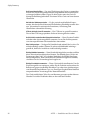
Symbole am Produkt
Die folgenden Symbole können sich am Produkt befinden:
Weist auf eine gefährliche Hochspannung im Gerätegehäuse
hin, die stark genug sein kann, um eine Stromschlaggefahr
darzustellen.
Weist darauf hin, dass der Benutzer, Bediener oder Servicetechniker wichtige Bedienungs-, Wartungs- oder Serviceanweisungen in den Produkthandbüchern lesen sollte.
Dies ist eine Aufforderung, beim Wechsel von Sicherungen
auf deren Nennwert zu achten. Die im Text angegebene Sicherung muss durch eine Sicherung ersetzt werden, die die
angegebenen Nennwerte besitzt.
Weist auf eine Schutzerdungsklemme hin, die mit dem
Erdungskontakt verbunden werden muss, bevor weitere Ausrüstungskomponenten angeschlossen werden.
Weist auf eine externe Schutzerdungsklemme hin, die als
Ergänzung zu einem internen Erdungskontakt an die Erde
angeschlossen werden kann.
Weist darauf hin, dass es statisch empfindliche Komponenten
gibt, die durch eine elektrostatische Entladung beschädigt
werden können. Verwenden Sie antistatische Prozeduren,
Ausrüstung und Oberflächen während der Wartung.
Warnungen
Die folgenden Warnungen weisen auf Bedingungen oder Vorgehensweisen
hin, die Verletzungs- oder Lebensgefahr bergen:
Gefährliche Spannungen oder Ströme — Schalten Sie den Strom ab, und ent-
fernen Sie ggf. die Batterie, bevor sie Schutzabdeckungen abnehmen, löten
oder Komponenten austauschen.
Servicearbeiten nicht alleine ausführen — Führen Sie interne Servicearbeiten nur
aus, wenn eine weitere Person anwesend ist, die erste Hilfe leisten und
Wiederbelebungsmaßnahmen einleiten kann.
Schmuck abnehmen — Legen Sie vor Servicearbeiten Schmuck wie Ringe,
Uhren und andere metallische Objekte ab.
18
APEX — Installation and Service Manual
Safety Summary
Keine offen liegenden Leiter berühren — Berühren Sie bei eingeschalteter Strom-
zufuhr keine offen liegenden Leitungen, Komponenten oder Schaltungen.
Richtiges Netzkabel verwenden — Verwenden Sie nur das mitgelieferte Netzk-
abel oder ein Netzkabel, das den Spezifikationen für dieses Produkt
entspricht.
Gerät erden — Schließen Sie den Erdleiter des Netzkabels an den Erdung-
skontakt an.
Gerät nur mit angebrachten Abdeckungen und Gehäuseseiten betreiben — Schalten Sie
dieses Gerät nicht ein, wenn die Abdeckungen oder Gehäuseseiten entfernt
wurden.
Richtige Sicherung verwenden — Verwenden Sie nur Sicherungen, deren Typ
und Nennwert den Spezifikationen für dieses Produkt entsprechen.
Gerät nur in trockener Umgebung verwenden — Betreiben Sie das Gerät nicht in
nassen oder feuchten Umgebungen.
Gerät nur verwenden, wenn keine Explosionsgefahr besteht — Verwenden Sie dieses
Produkt nur in Umgebungen, in denen keinerlei Explosionsgefahr besteht.
Hohe Kriechströme — Das Gerät muss vor dem Einschalten unbedingt geerdet
werden.
Doppelte Spannungsversorgung kann vorhanden sein — Schließen Sie die beiden
Anschlußkabel an getrennte Stromkreise an. Vor Servicearbeiten sind beide
Anschlußkabel vom Netz zu trennen.
Zweipolige, neutrale Sicherung — Schalten Sie den Netzstrom ab, bevor Sie mit
den Servicearbeiten beginnen.
Fassen Sie das Gerät beim Transport richtig an — Halten Sie das Gerät beim Trans-
port nicht an Türen oder anderen beweglichen Teilen fest.
Gefahr durch mechanische Teile — Warten Sie, bis der Lüfter vollständig zum
Halt gekommen ist, bevor Sie mit den Servicearbeiten beginnen.
Vorsicht
Die folgenden Vorsichtshinweise weisen auf Bedingungen oder Vorgehensweisen hin, die zu Schäden an Ausrüstungskomponenten oder
anderen Gegenständen führen können:
Gerät nicht öffnen — Durch das unbefugte Öffnen wird die Garantie ungültig.
Richtige Spannungsquelle verwenden — Betreiben Sie das Gerät nicht an einer
Spannungsquelle, die eine höhere Spannung liefert als in den Spezifikationen für dieses Produkt angegeben.
APEX — Installation and Service Manual
19
Safety Summary
Gerät ausreichend belüften — Um eine Überhitzung des Geräts zu vermeiden,
müssen die Ausrüstungskomponenten entsprechend den Installationsanweisungen belüftet werden. Legen Sie kein Papier unter das Gerät. Es
könnte die Belüftung behindern. Platzieren Sie das Gerät auf einer ebenen
Oberfläche.
Antistatische Vorkehrungen treffen — Es gibt statisch empfindliche Kompo-
nenten, die durch eine elektrostatische Entladung beschädigt werden können. Verwenden Sie antistatische Prozeduren, Ausrüstung und
Oberflächen während der Wartung.
CF-Karte nicht mit einem PC verwenden — Die CF-Karte ist speziell formatiert.
Die auf der CF-Karte gespeicherte Software könnte gelöscht werden.
Gerät nicht bei eventuellem Ausrüstungsfehler betreiben — Wenn Sie einen Produk-
tschaden oder Ausrüstungsfehler vermuten, lassen Sie die Komponente
von einem qualifizierten Servicetechniker untersuchen.
Kabel richtig verlegen — Verlegen Sie Netzkabel und andere Kabel so, dass Sie
nicht beschädigt werden. Stützen Sie schwere Kabelbündel ordnungsgemäß ab, damit die Anschlüsse nicht beschädigt werden.
Richtige Netzkabel verwenden — Wenn Netzkabel mitgeliefert wurden, erfüllen
diese alle nationalen elektrischen Normen. Der Betrieb dieses Geräts mit
Spannungen über 130 V AC erfordert Netzkabel, die NEMA-Konfigurationen entsprechen. Wenn internationale Netzkabel mitgeliefert wurden,
sind diese für das Verwendungsland zugelassen.
Richtige Ersatzbatterie verwenden — Dieses Gerät enthält eine Batterie. Um die
Explosionsgefahr zu verringern, prüfen Sie die Polarität und tauschen die
Batterie nur gegen eine Batterie desselben Typs oder eines gleichwertigen,
vom Hersteller empfohlenen Typs aus. Entsorgen Sie gebrauchte Batterien
entsprechend den Anweisungen des Batterieherstellers.
Das Gerät enthält keine Teile, die vom Benutzer gewartet werden können.
Wenden Sie sich bei Problemen bitte an den nächsten Händler.
20
APEX — Installation and Service Manual
Safety Summary
Consignes de sécurité
Il est recommandé de lire, de bien comprendre et surtout de respecter les
informations relatives à la sécurité qui sont exposées ci-après, notamment
les consignes destinées à prévenir les risques d’incendie, les décharges électriques et les blessures aux personnes. Les avertissements complémentaires, qui ne sont pas nécessairement repris ci-dessous, mais présents dans
toutes les sections du manuel, sont également à prendre en considération.
AVERTISSEMENT Toutes les instructions présentes dans ce manuel qui concernent
l’ouverture des capots ou des logements de cet équipement sont
destinées exclusivement à des membres qualifiés du personnel de
maintenance. Afin de diminuer les risques de décharges
électriques, ne procédez à aucune intervention d’entretien autre
que celles contenues dans le manuel de l’utilisateur, à moins que
vous ne soyez habilité pour le faire.
Consignes et symboles de sécurité
Termes utilisés dans ce manuel
Les consignes de sécurité présentées dans ce manuel peuvent apparaître
sous les formes suivantes:
AVERTISSEMENT Les avertissements signalent des conditions ou des pratiques
susceptibles d’occasionner des blessures graves, voire même
fatales.
ATTENTION
Les mises en garde signalent des conditions ou des pratiques
susceptibles d’occasionner un endommagement à l’équipement ou
aux installations, ou de rendre l’équipement temporairement non
opérationnel, ce qui peut porter préjudice à vos activités.
Signalétique apposée sur le produit
La signalétique suivante peut être apposée sur le produit:
DANGER — risque de danger imminent pour l’utilisateur.
AVERTISSEMENT — Risque de danger non imminent pour l’utilisateur.
MISE EN GARDE — Risque d’endommagement du produit, des installations
ou des autres équipements.
APEX — Installation and Service Manual
21
Safety Summary
Symboles apposés sur le produit
Les symboles suivants peut être apposés sur le produit:
Signale la présence d’une tension élevée et dangereuse dans le
boîtier de l’équipement ; cette tension peut être suffisante
pour constituer un risque de décharge électrique.
Signale que l’utilisateur, l’opérateur ou le technicien de maintenance doit faire référence au(x) manuel(s) pour prendre connaissance des instructions d’utilisation, de maintenance ou
d’entretien.
Il s’agit d’une invite à prendre note du calibre du fusible lors
du remplacement de ce dernier. Le fusible auquel il est fait
référence dans le texte doit être remplacé par un fusible du
même calibre.
Identifie une borne de protection de mise à la masse qui doit
être raccordée correctement avant de procéder au raccordement des autres équipements.
Identifie une borne de protection de mise à la masse qui peut
être connectée en tant que borne de mise à la masse supplémentaire.
Signale la présence de composants sensibles à l’électricité statique et qui sont susceptibles d’être endommagés par une
décharge électrostatique. Utilisez des procédures, des équipements et des surfaces antistatiques durant les interventions
d’entretien.
Avertissements
Les avertissements suivants signalent des conditions ou des pratiques susceptibles d’occasionner des blessures graves, voire même fatales:
Présence possible de tensions ou de courants dangereux — Mettez hors tension,
débranchez et retirez la pile (le cas échéant) avant de déposer les couvercles
de protection, de défaire une soudure ou de remplacer des composants.
Ne procédez pas seul à une intervention d’entretien — Ne réalisez pas une intervention d’entretien interne sur ce produit si une personne n’est pas présente
pour fournir les premiers soins en cas d’accident.
Retirez tous vos bijoux — Avant de procéder à une intervention d’entretien,
retirez tous vos bijoux, notamment les bagues, la montre ou tout autre objet
métallique.
22
APEX — Installation and Service Manual
Safety Summary
Évitez tout contact avec les circuits exposés — Évitez tout contact avec les connex-
ions, les composants ou les circuits exposés s’ils sont sous tension.
Utilisez le cordon d’alimentation approprié — Utilisez exclusivement le cordon
d’alimentation fourni avec ce produit ou spécifié pour ce produit.
Raccordez le produit à la masse — Raccordez le conducteur de masse du cordon
d’alimentation à la borne de masse de la prise secteur.
Utilisez le produit lorsque les couvercles et les capots sont en place — N’utilisez pas
ce produit si les couvercles et les capots sont déposés.
Utilisez le bon fusible — Utilisez exclusivement un fusible du type et du
calibre spécifiés pour ce produit.
Utilisez ce produit exclusivement dans un environnement sec — N’utilisez pas ce
produit dans un environnement humide.
Utilisez ce produit exclusivement dans un environnement non explosible — N’utilisez
pas ce produit dans un environnement dont l’atmosphère est explosible.
Présence possible de courants de fuite — Un raccordement à la masse est indis-
pensable avant la mise sous tension.
Deux alimentations peuvent être présentes dans l’équipement — Assurez vous que
chaque cordon d’alimentation est raccordé à des circuits de terre séparés.
Débranchez les deux cordons d’alimentation avant toute intervention.
Fusion neutre bipolaire — Débranchez l’alimentation principale avant de pro-
céder à une intervention d’entretien.
Utilisez les points de levage appropriés — Ne pas utiliser les verrous de la porte
pour lever ou déplacer l’équipement.
Évitez les dangers mécaniques — Laissez le ventilateur s’arrêter avant de pro-
céder à une intervention d’entretien.
Mises en garde
Les mises en garde suivantes signalent les conditions et les pratiques susceptibles d’occasionner des endommagements à l’équipement et aux installations:
N’ouvrez pas l’appareil — Toute ouverture prohibée de l’appareil aura pour
effet d’annuler la garantie.
Utilisez la source d’alimentation adéquate — Ne branchez pas ce produit à une
source d’alimentation qui utilise une tension supérieure à la tension nominale spécifiée pour ce produit.
APEX — Installation and Service Manual
23
Safety Summary
Assurez une ventilation adéquate — Pour éviter toute surchauffe du produit,
assurez une ventilation de l’équipement conformément aux instructions
d’installation. Ne déposez aucun document sous l’appareil — ils peuvent
gêner la ventilation. Placez l’appareil sur une surface plane.
Utilisez des procédures antistatiques - Les composants sensibles à l’électricité
statique présents dans l’équipement sont susceptibles d’être endommagés
par une décharge électrostatique. Utilisez des procédures, des équipements
et des surfaces antistatiques durant les interventions d’entretien.
N’utilisez pas la carte CF avec un PC — La carte CF a été spécialement formatée.
Le logiciel enregistré sur la carte CF risque d’être effacé.
N’utilisez pas l’équipement si un dysfonctionnement est suspecté — Si vous sus-
pectez un dysfonctionnement du produit, faites inspecter celui-ci par un
membre qualifié du personnel d’entretien.
Acheminez les câbles correctement — Acheminez les câbles d’alimentation et les
autres câbles de manière à ce qu’ils ne risquent pas d’être endommagés.
Supportez correctement les enroulements de câbles afin de ne pas endommager les connecteurs.
Utilisez les cordons d’alimentation adéquats — Les cordons d’alimentation de cet
équipement, s’ils sont fournis, satisfont aux exigences de toutes les réglementations régionales. L’utilisation de cet équipement à des tensions
dépassant les 130 V en c.a. requiert des cordons d’alimentation qui satisfont
aux exigences des configurations NEMA. Les cordons internationaux, s’ils
sont fournis, ont reçu l’approbation du pays dans lequel l’équipement est
utilisé.
Utilisez une pile de remplacement adéquate — Ce produit renferme une pile. Pour
réduire le risque d’explosion, vérifiez la polarité et ne remplacez la pile que
par une pile du même type, recommandée par le fabricant. Mettez les piles
usagées au rebut conformément aux instructions du fabricant des piles.
Cette unité ne contient aucune partie qui peut faire l’objet d’un entretien
par l’utilisateur. Si un problème survient, veuillez contacter votre distributeur local.
24
APEX — Installation and Service Manual
Regulatory Notices
Certifications and Compliances
FCC Emission Control
This equipment has been tested and found to comply with the limits for a
Class A digital device, pursuant to Part 15 of the FCC Rules. These limits
are designed to provide reasonable protection against harmful interference
when the equipment is operated in a commercial environment. This equipment generates, uses, and can radiate radio frequency energy and, if not
installed and used in accordance with the instruction manual, may cause
harmful interference to radio communications. Operation of this equipment in a residential area is likely to cause harmful interference in which
case the user will be required to correct the interference at his own expense.
Changes or modifications not expressly approved by Grass Valley Group
can affect emission compliance and could void the user’s authority to
operate this equipment.
Canadian EMC Notice of Compliance
This digital apparatus does not exceed the Class A limits for radio noise
emissions from digital apparatus set out in the Radio Interference Regulations of the Canadian Department of Communications.
Le présent appareil numérique n’emet pas de bruits radioélectriques
dépassant les limites applicables aux appareils numeriques de la classe A
préscrites dans le Règlement sur le brouillage radioélectrique édicte par le
ministère des Communications du Canada.
EN 55103 Class A Warning
For products that comply with Class A. In a domestic environment this
product may cause radio interference in which case the user may be
required to take adequate measures.
APEX — Installation and Service Manual
25
Regulatory Notices
Canadian Certified Power Cords
Canadian approval includes the products and power cords appropriate for
use in the North America power network. All other power cords supplied
are approved for the country of use.
Canadian Certified AC Adapter
Canadian approval includes the AC adapters appropriate for use in the
North America power network. All other AC adapters supplied are
approved for the country of use.
Laser Compliance
Laser Safety Requirements
The device used in this product is a Class 1 certified laser product. Operating this product outside specifications or altering from its original design
may result in hazardous radiation exposure, and may be considered an act
of modifying or new manufacturing of a laser product under U.S. regulations contained in 21CFR Chapter1, subchapter J or CENELEC regulations
in HD 482 S1. People performing such an act are required by law to recertify
and reidentify this product in accordance with provisions of 21CFR subchapter J for distribution within the U.S.A., and in accordance with
CENELEC HD 482 S1 for distribution within countries using the IEC 825
standard.
Laser Safety
Laser safety in the United States is regulated by the Center for Devices and
Radiological Health (CDRH). The laser safety regulations are published in
the “Laser Product Performance Standard,” Code of Federal Regulation
(CFR), Title 21, Subchapter J.
The international Electrotechnical Commission (IEC) Standard 825, “Radiation of Laser Products, Equipment Classification, Requirements and
User’s Guide,” governs laser products outside the United States. Europe
and member nations of the European Free trade Association fall under the
jurisdiction of the Comite European de Normalization Electrotechnique
(CENELEC).
For the CDRH: The radiant power is detected trough a 7 mm aperture at a
distance of 200 mm from the source focused through a lens with a focal
length of 100 mm.
For IEC compliance: The radiant power is detected trough a 7 mm aperture
at a distance of 100 mm from the source focused through a lens with a focal
length of 100 mm.
26
APEX Installation and Service Manual
Regulatory Notices
FCC Emission Limits
This device complies with Part 15 of the FCC Rules. Operation is subject to
the following two conditions: (1) This device may no cause harmful interference, and (2) this device must accept any interference received,
including interference that may cause undesirable operation. This device
has been tested and found to comply with FCC Part 15 Class B limits for a
digital device when tested with a representative laser-based fiber optical
system that complies with ANSI X3T11 Fiber Channel Standard.
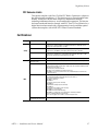
Certifications:
Category
Standard
Designed/tested for compliance with:
ANSI / UL60950
“Standard for Safety of Information Technology Equipment - Safety - Part 1: General
Requirements”, (ANSI/UL 60950-1, First Edition, Dated April 1, 2003, with revision
through and including November 26, 2003.)
IEC 60950
“Standard for Safety for Information Technology Equipment - Safety - Part 1: General
Requirements”, (IEC 60950-1, First Edition, 2001, Corrigendum 1:10-2002)
CAN/CSA C22.2, No. 60950
“Standard for Safety of Information Technology Equipment - Safety - Part 1: General
Requirements”, (CAN/CSA-C22.2 No. 60950-1-03. First Edition Dated April 1, 2003,
with revisions through and including November 26, 2003)
EN60950
Safety of Information Technology Equipment, including Electrical Business Equipment.
EMC Directive 89/336/EEC via
EN 55103-1 and 2
Audio, Video and Entertainment Lighting Control for the European Community.
EN 55103-1 standards
Electromagnetic compatibility.
Product family standard for audio, video, audio-visual and entertainment lighting control
apparatus for professional use.
Part 1 Emissions, Environment E1/E2
EN 55022: Class A Radiated and Conducted Emissions
EN 61000-3-2: Power Line Harmonic Emissions, Radiated Magnetic Field Emissions,
Peak Inrush Current
EN55103-2 standards
Electromagnetic compatibility--Product family standard for audio, video, audio-visual
and entertainment lighting control apparatus for professional use.
Part 2 Immunity, Environment E1/E2
EN 50082-1: Immunity
EN 61000-4-2:
Electrostatic Discharge “ESD” Immunity
EN 61000-4-3:
Radiated RF Electromagnetic Field Immunity
EN 61000-4-4:
Electrical Fast Transient/Burst “EFT” Immunity
EN 61000-4-5: Surge Immunity
EN 61000-4-6: Conducted RF Immunity
EN 61000-4-11: Voltage Dips, Short Interruptions and Voltage Variations
Annex A - Radiated Magnetic Field Immunity
Note: This only applies to assemblies sensitive to magnetic fields
US FCC Class A
Canada FCC Industry Canada
CISPR Pub. 22 (1985)
Safety
EMI
APEX — Installation and Service Manual
27
Regulatory Notices
28
APEX Installation and Service Manual
Section
1
Introduction
Apex Features
•
High-density, large-scale digital audio router based on 11 RU frame
with either 75 ohm unbalanced BNC connectors or 110 ohm balanced
DB25 connectors
•
In-frame expansion in blocks of 32 inputs/outputs, up to 256 x 256 AES
pairs
•
Connect multiple frames for larger systems:
•
Standard Apex frames for systems up to 1024 x 1024 AES pairs
•
Apex Plus frames for systems up to 2048 x 2048 AES pairs
•
Simultaneous synchronous/asynchronous support for 30 kHz to
100 kHz signals
•
Conforms to AES 3, AES3 id, AES 75, and AES 110 specifications
•
Dolby E support
•
Supports Jupiter and Encore control systems [Encore control requires
connection to an NR-33000 Sync/NIC/OPM (Broadlinx) board in
Trinix chassis]
•
All active components are front-loading and hot swappable
•
Redundancy options: control board, matrix board, and power supply
•
Various stereo modes supported, including mix and reverse
•
Two video and two audio sync reference inputs per chassis
•
MADI ports
•
Silent Switching with programmable V-fade
•
Output monitor ports for quality control (Standard Apex models only)
•
Supported extended chassis links, up to 5km apart, using fiber interconnect (Standard Apex Models Only.)
APEX — Installation and Service Manual
29
Section 1 — Introduction
The Apex Digital Audio Router is designed to provide the highest density
and most reliable audio router available for large-scale infrastructures,
offering adaptability, reliability, and serviceability while using less power
and less space than comparable systems.
Scaling up to 2048 x 2048 is achieved via a unique Time Division Multiplexing (TDM) switching architecture, which offers the simplest expansion
path available for both studio and mobile users using only a handful of
interconnection cables and without the need for expensive distribution
amplifiers.
The system supports simultaneous synchronous and asynchronous signals
from 30 to 100 kHz.
The Apex system offers a similar physical flexibility. The chassis can be
stacked vertically or horizontally. Chassis interconnect cables are four
meters (13 ft.) long.
Note
The InfiniBand cables cannot be longer than four meters (13 feet).
To ensure even, uninterrupted cooling, the Apex system uses forced air
cooling. Additionally, the Apex system design curbs overall power utilization by minimizing circuit board and component counts. For example, the
I/O boards feature a configurable design that minimizes components and
power requirements. This significantly reduces the load on the cooling
system, increasing the overall reliability of the system.
The Apex Digital Audio Router also offers maximum serviceability. Its
passive rear panel allows all modules to be hot swapped from the front of
the chassis—even power supplies and fans. This approach allows you to
keep the router online during upgrades and to avoid going behind the
equipment rack to perform any service-oriented tasks.
For increased reliability, Thomson Grass Valley recommends the installation of redundant control boards, matrix boards, and power supplies.
30
APEX — Installation and Service Manual
Section
2
Planning Guide
This section provides details necessary for planning, ordering, and
installing an Apex Digital Audio Router.
The beginning of this section includes conceptual descriptions and drawings for those who need a basic understanding of the product and the configuration options. Later subsections provide additional detail such as
Router specifications and ordering information.
Note
If you are actually installing the router at this time, please refer to
Section 3-Installation.
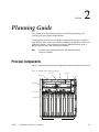
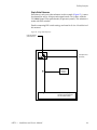
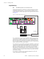
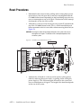
Principal Components
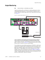
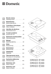
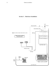
Figure 1 illustrates the principle components with the front door removed.
Figure 1. Example of 256 x 256 Apex System
Control Board B
Control Board A
Matrix Board A
License Board
Fan Module
Matrix Board B
Power Supply B
Power supply A
Input/Output boards
APEX — Installation and Service Manual
31
Section 2 — Planning Guide
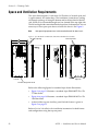
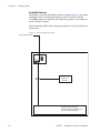
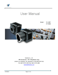
Space and Ventilation Requirements
The Apex frame requires 11 rack units (19.25 inches) of vertical space and
is approximately 10.3 inches deep. The ventilation system draws cooling
air through openings all along the bottom and in the top third of the left
side. Warm air is exhausted through two fans located in the top right side.
The left and right sides must therefore be kept clear of obstructions. It is not
necessary to leave open space above or below the chassis. See Figure 2.
Note
Heat-generating equipment must not be mounted beneath the Apex chassis.
Figure 2. Apex RF-34075 75 Ohm Frame (RF-34110 110 Ohm Frame Similar)
Dual exhaust fans
Air intake openings
10.281
9.100
19.220
11 RU
Left side
Front
Right side
Air intake along bottom of unit
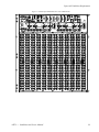
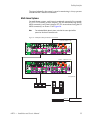
Refer to the following figures for standard Apex frame illustrations:
•
Figure 3 on page 33 illustrates a standard Apex FRM-34075 256 x 256
75 Ohm frame.
•
Figure 4 on page 34 illustrates a standard Apex FRM-34110 256 x 256
110 Ohm frame.
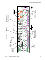
•
A detail of the top rear Auxiliary panel for both frames is given in
Figure 5 on page 35.
Refer to Section 3-Installation for installation instructions for both frames
and configuration using the top rear panel.
32
APEX — Installation and Service Manual
Space and Ventilation Requirements
Figure 3. Standard Apex FRM-34075 256 x 256 75 Ohm Frame
1536
1792
2048
E
X
P
A
1
2
EXPANSION
VID REF A
3
LOWEST
MC A
OUT
4
HIGHEST
IN
OP MON A
OUT
APEX — Installation and Service Manual
E
X
P
B
2
1
EXPANSION
VID REF B
3
LOWEST
AES REF A
MC B
OUT
4
HIGHEST
IN
OP MON B
AES REF B
OUT
33
Section 2 — Planning Guide
Figure 4. Standard Apex FRM-34110 256 x 256 110 Ohm Frame
1536
1792
2048
E
X
P
A
1
2
3
LOWEST
MC A
OUT
34
VID REF A
EXPANSION
OUT
4
HIGHEST
IN
OP MON A
VID REF B
EXPANSION
E
X
P
B
2
1
3
LOWEST
AES REF A
MC B
OUT
4
HIGHEST
IN
OP MON B
AES REF B
OUT
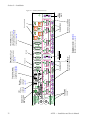
APEX — Installation and Service Manual
Alarm connector
(SMPTE standard
269M-1999) (see
page 61)
APEX — Installation and Service Manual
OUT
Power inputs
100 to 240 V,
50-60 Hz
E
X
P
A
SW 1 Apex Plus
system size
select
OUT
MC A
LOWEST
1
IN
2
3
4
HIGHEST
AES REF A
E
X
P
B
OUT
Not used
Video Reference
Input A
VID REF A
Factory use
Frame number.
Master Clock and InfiniBand®
connections to “A” Matrix board
AES Audio
Reference
Output Monitor
OP MON A
EXPANSION
256
512 768
1024
1280
1536
1792
2048
Max size standard Apex
system size select
Physical level number
used by control system.
OUT
MC B
LOWEST
1
IN
2
3
AES REF B
HIGHEST
4
Not presently used
Master Clock and InfiniBand®
connections to “B” Matrix board
AES Audio
Reference
Output Monitor
OP MON B
EXPANSION
Crosspoint bus connection to
Jupiter VM/CM controller or to
Trinix video router. Also used for
indirect connection to Encore.
Video
Reference
Input B
VID REF B
Space and Ventilation Requirements
Figure 5. Auxiliary Panel
35
Section 2 — Planning Guide
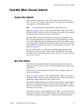
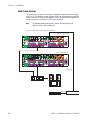
Expanded (Multi-Chassis) Systems
Standard Apex Models
With a standard Apex chassis, 256 x 256 frames can be connected to form
512 x 512, 768 x 768, or 1024 x 1024 systems. The frames are connected by
four-meter (13 ft.) InfiniBand cables.
Note
The InfiniBand cables cannot be longer than four meters (13 feet).
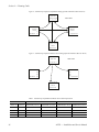
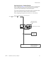
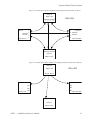
Figure 6 on page 38 shows a fully expanded (1024 x 1024) system with 6
InfiniBand expansion cables. Smaller systems will require fewer cables (see
Table 1 on page 38); the connector numbering scheme remains the same as
that shown for the large system. As shown in Figure 5, each group of four
InfiniBand Expansion connectors correspond to one MX-34000 Matrix
board.
Expanded Apex systems with more than one chassis require RG-59 or RG-6
Master Clock connections in addition to the InfiniBand cables. The three
Master Clock Out connectors are functionally identical, i.e., they can be
connected to any chassis. See Figure 7 on page 38. As shown on Figure 5 on
page 35, each group of four Master Clock BNC connectors corresponds to
a Matrix board.
If two or more frames of a multi-frame standard Apex system must be
located more than four meters apart, 2 each model APX-FBR-EXT Apex
Fiber Extenders must be ordered for each remote chassis. Refer to Fiber
Extenders (Standard Apex Only) on page 45.
Apex Plus Models
If a 2048 x 2048 system is required (or later expansion to that size is anticipated), the Apex Plus frame type is used. Apex Plus frames have either
input boards only or output boards only. For a 2048 x 2048 system, eight
Apex Plus frames would be needed: four with 512 inputs each, and four
with 512 outputs each. Systems may be asymmetrical if desired (having an
unequal number of inputs and outputs).
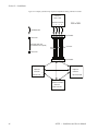
The illustration in Figure 8 shows a fully expanded (2048 x 2048) system
with 16 InfiniBand cables (optional redundant cables are not shown).
Smaller systems will require fewer cables; the connector numbering
scheme remains the same as that shown for the large system.
Note
36
The InfiniBand cables cannot be longer than four meters (13 feet).
APEX — Installation and Service Manual
Expanded (Multi-Chassis) Systems
Expanded Apex Plus systems require RG-59 or RG-6 coax Master Clock
connections in addition to the InfiniBand cables. Master Clock cabling is
shown for all systems in the following figures:
•
512 inputs (Figure 9 on page 41),
•
1024 inputs (Figure 10 on page 42),
•
1536 inputs (Figure 11 on page 43), and
•
2048 inputs (Figure 12 on page 44).
Refer to Table 2 on page 40 for cabling information.
As shown on Figure 5 on page 35, each group of four Expansion (InfiniBand) connectors, and each group of four Master Clock BNC connectors
correspond to one MX-34000 Matrix board. The three Master Clock Out
connectors are functionally identical, i.e., they can be connected to any
chassis.
Notes
1. Redundant InfiniBand and Master Clock cables (not shown in the
drawings) can be added if each chassis is equipped with a secondary
matrix board. In this case the Expansion B connectors would be used.
2. Only one CX-34000 Control Crosspoint board is required per system,
regardless of expansion.
3. Fiber Extenders cannot be used with the Apex Plus router.
4. If you are thinking of expanding the Apex router beyond the 1024
configuration, planning for expansion should be done before
purchasing. The Apex and Apex plus frames are different. For example,
the Apex symmetrical frame cannot be later expanded to a 2048x2048
configuration.
APEX — Installation and Service Manual
37
Section 2 — Planning Guide
Figure 6. Standard Apex Expansion InfiniBand Cabling (optional redundant cables not shown)
Chassis 0
Inputs 1-256
1024 x 1024
Expansion connector
1 2 3 4
2 Expansion
connector
3
Expansion 3
connector 2
Inputs 257-512
Chassis 3
1
1
Chassis 1
4
4
Inputs 769-1024
2
1 3
4
Expansion connector
Chassis 2
Inputs 513-768
Figure 7. Standard Apex Expansion Master Clock Cabling (optional redundant cables not shown)
Chassis 0
Inputs 1-256
1024 x 1024
Out Out Out In
In
In
Chassis 1
Inputs 257-512
Out
Out
Out
Out
Out
Out
Chassis 3
Inputs 769-1024
In
Out Out Out
Chassis 2
Inputs 513-768
Table 1. Standard Apex InfiniBand and Master Clock Cable Requirements
InfiniBand cables needed
38
Master Clock cables needed
Switcher size
# of Chassis
Non-redundant
(1 Matrix board per chassis)
Redundant
(2 Matrix boards per chassis)
Non-redundant
(1 Matrix board per chassis)
Redundant
(2 Matrix boards per chassis)
256 x 256
1
0
0
0
0
512 x 512
2
1
2
1
2
768 x 768
3
3
6
2
4
1024 x 1024
4
6
12
3
6
APEX — Installation and Service Manual
Expanded (Multi-Chassis) Systems
Figure 8. Apex Plus Expansion InfiniBand Cabling (optional redundant cables not shown)
2048 x 2048
Input chassis 0
1
2
3
4
Input chassis
0
Input chassis
1
1
1
Output chassis 4
1
2
3
4
Output chassis 5
1
IN
2
2
2
OUT
OUT
3
3
3
4
4
OUT
4
Input chassis 2
1
2
Output chassis 6
1
2
3
3
4
4
Input chassis 4
1
Output chassis 7
1
2
2
3
3
4
4
APEX — Installation and Service Manual
39
Section 2 — Planning Guide
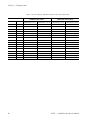
Table 2. Apex Plus Expansion InfiniBand and Master Clock Cable Requirements
InfiniBand cables needed
Master Clock cables needed
Switcher size
# of Chassis
Non-redundant
(1 Matrix board per chassis)
512 x 512
2
1
2
1
2
512 x 1024
3
2
4
2
4
512 x 1536
4
3
6
3
6
512 x 2048
5
4
8
4
8
1024 x 512
3
2
4
2
4
1024 x 1024
4
4
8
3
6
1024 x 1536
5
6
12
4
8
1024 x 2048
6
8
16
5
10
1536 x 512
4
3
6
3
6
1536 x 1024
5
6
12
4
8
1536 x 1536
6
9
18
5
10
1536 x 2048
7
12
24
6
12
2048 x 512
5
4
8
4
8
2048 x 1024
6
8
16
5
10
2048 x 1536
7
12
24
6
12
2048 x 2048
8
16
32
7
14
40
Redundant
(2 Matrix boards per chassis)
Non-redundant
(1 Matrix board per chassis)
Redundant
(2 Matrix boards per chassis)
APEX — Installation and Service Manual
Expanded (Multi-Chassis) Systems
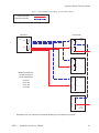
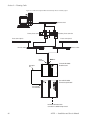
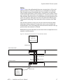
Figure 9. Apex Plus Master Clock Cabling - Systems with 512 Inputs
Primary connections
Redundant connections
Input frames
Frame 0
1-512
MC B
MC A
Output frames
IN
OUT
OUT
OUT
IN
OUT
OUT
OUT
Master Clock Distribution
For Apex Plus Systems
with the following sizes:
512 X 512
512 X 1024
512 X 1536
512 X 2048
Frame 4
1-512
IN
OUT
OUT
OUT
MC B
IN
OUT
OUT
OUT
MC A
Frame 5
513-1024
IN
OUT
OUT
OUT
MC B
IN
OUT
OUT
OUT
MC A
Frame 6
1025-1536
IN
OUT
OUT
OUT
MC B
IN
OUT
OUT
OUT
MC A
IN
OUT
OUT
OUT
MC B
IN
OUT
OUT
OUT
MC A
Frame 7
1537-2048
Note: Master Clock "Out" connectors are functionally identical (they can be attached to any chassis).
APEX — Installation and Service Manual
41
Section 2 — Planning Guide
Figure 10. Apex Plus Master Clock Cabling - Systems with 1024 Inputs
Primary connections
Redundant connections
Input frames
Frame 0
1-512
MC B
MC A
Frame 1
513-1024
Output frames
IN
OUT
OUT
OUT
IN
OUT
OUT
OUT
Frame 4
1-512
IN
OUT
OUT
OUT
MC B
IN
OUT
OUT
OUT
MC A
Frame 5
513-1024
MC B
IN
OUT
OUT
OUT
IN
OUT
OUT
OUT
MC B
MC A
IN
OUT
OUT
OUT
IN
OUT
OUT
OUT
MC A
Master Clock Distribution
For Apex Plus Systems
with the following sizes:
1024 X 512
1024 X 1024
1024 X 1536
1024 X 2048
Frame 6
1025-1536
IN
OUT
OUT
OUT
MC B
IN
OUT
OUT
OUT
MC A
IN
OUT
OUT
OUT
MC B
IN
OUT
OUT
OUT
MC A
Frame 7
1537-2048
Note: Master Clock "Out" connectors are functionally identical (they can be attached to any chassis).
42
APEX — Installation and Service Manual
Expanded (Multi-Chassis) Systems
Figure 11. Apex Plus Master Clock Cabling - Systems with 1536 Inputs
Primary connections
Redundant connections
Frame 0
MC B
IN
OUT
OUT
OUT
IN
MC A OUT
OUT
OUT
Frame 4
IN
OUT
OUT
OUT
MC B
IN
OUT
OUT
OUT
MC A
Frame 1
MC B
MC A
IN
OUT
OUT
OUT
IN
OUT
OUT
OUT
Frame 5
IN
OUT
OUT
OUT
MC B
IN
OUT
OUT
OUT
MC A
Frame 2
MC B
IN
OUT
OUT
OUT
MC A
IN
OUT
OUT
OUT
Frame 6
IN
OUT
OUT
OUT
MC B
IN
OUT
OUT
OUT
MC A
Frame 7
Master Clock Distribution
For Apex Plus Systems
with the following sizes
IN
OUT
OUT
OUT
MC B
1536 X 0512
1536 X 1024
1536 X 1536
1536 X 2048
IN
OUT
OUT
OUT
MC A
APEX — Installation and Service Manual
43
Section 2 — Planning Guide
Figure 12. Apex Plus Master Clock Cabling - Systems with 2048 Inputs
Primary connections
Redundant connections
Frame 0
MC B
IN
OUT
OUT
OUT
IN
MC A OUT
OUT
OUT
Frame 4
IN
OUT
OUT
OUT
MC B
IN
OUT
OUT
OUT
MC A
Frame 1
MC B
MC A
IN
OUT
OUT
OUT
Frame 5
IN
OUT
OUT
OUT
IN
OUT
OUT
OUT
MC B
IN
OUT
OUT
OUT
MC A
Frame 2
MC B
IN
OUT
OUT
OUT
MC A
IN
OUT
OUT
OUT
MC B
IN
OUT
OUT
OUT
IN
OUT
OUT
OUT
MC B
MC A
IN
OUT
OUT
OUT
IN
OUT
OUT
OUT
MC A
Frame 6
IN
OUT
OUT
OUT
MC B
IN
OUT
OUT
OUT
MC A
Frame 3
Master Clock Distribution
For Apex Plus Systems
with the following sizes
Frame 7
2048 X 0512
2048 X 1024
2048 X 1536
2048 X 2048
Note: Master Clock “Out” connectors are functionally identical (they can be attached to any chassis).
44
APEX — Installation and Service Manual
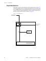
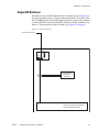
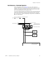
Expanded (Multi-Chassis) Systems
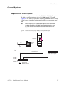
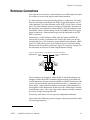
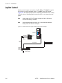
Fiber Extenders (Standard Apex Only)
Fiber Extenders are used to connect a Remote chassis or system to a Local
chassis. In general, you need one Fiber extender per individual or group of
remote Apex chassis. Any local chassis (chassis that are located closer than
four meters) can use InfiniBand cables. If two or more frames of a
multi-frame standard Apex system must be located more than four meters
apart, a minimum of two (2) Apex Fiber Extenders, model APX-FBR-EXT,
must be ordered to connect the Remote chassis to the local chassis. See
Figure 14 (optional redundant cables are not shown).
Two lengths of fiber optic cable are available: 300 meters (984 feet) and 5000
meters (16,400 feet or 3.1 miles). If the 300 meter cables are used, then the
Fiber Extenders should be ordered with APX-SFP-M300 small form-factor
plug-in multi-mode transceivers; if 5 km cables are used, then
APX-SFP-S5000 small form-factor plug-in single-mode transceivers should
be ordered. Each optical cable pair requires two transceivers (which are
plugged into the Fiber Extender ports).
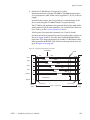
In the example shown in Figure 14 on page 46, a total of 12 transceivers
would be needed; i.e., one transceiver for each end of each fiber optic cable
pair. If redundant cables were installed, a total of 24 transceivers would be
needed for this system. Grass Valley recommends that you perform a complete optical power survey to precisely determine your systems' capability.
Each Fiber Extender is 1 RU high, approximately 12 inches (30.5 cm or
exactly 12.101357 inches) deep, which is the same depth as the Apex itself.
The Fiber Extender includes I/O ports for fiber optic cable connection to
the remote module and InfiniBand ports for connection to a local frame.
Each module also includes redundant power supplies and all rear panel
ports needed for redundant cabling. See Figure 13 below.
Note
Master clock cabling is not required for the remote frame(s) connected using
fiber extenders. The clock signal is recovered internally in this application.
Figure 13. Apex Fiber Extender: Front and Rear Views
APEX — Installation and Service Manual
45
Section 2 — Planning Guide
Figure 14. Example of Standard Apex Expansion InfiniBand Cabling with Fiber Extenders
Chassis 0
Inputs 1-256
Expansion connector
1 2 3 4
1024 x 1024
InfiniBand cable
T
1 2 3 4
TT TT TT TT
Transceiver
Fiber optic cable pair
(SFP transceivers required)
T
Fiber Extender
5 km max.
Transceiver
TT TT TT TT
1 2 3 4
Chassis 1
Expansion
connector
Inputs 257-512
Fiber Extender
Chassis 3
1
1
3
2
2
3
Expansion
connector
4
4
Inputs 769-1024
2
1 3 4
Expansion connector
Chassis 2
Inputs 513-768
46
APEX — Installation and Service Manual
Facility Interface
Facility Interface
Audio Signals
The multi-format support of the Apex router includes AES digital audio
75 Ohm unbalanced, and AES digital audio 110 Ohm balanced. Multiplexed Audio Digital Interface (MADI)1 and Dolby E support is provided.
The Apex chassis can accommodate four types of I/O boards:
•
75 Ohm, 32 input pairs
•
75 Ohm, 32 output pairs
•
110 Ohm, 32 input pairs
•
110 Ohm, 32 output pairs
A 256 x 256 75 Ohm system with eight input boards and eight output
boards is shown on Figure 3 on page 33.
A 256 x 256 110 Ohm system with eight input boards and eight output
boards is shown on Figure 4 on page 34. (Pinouts for the D connectors are
shown on Figure 38 on page 91.)
The Apex system can automatically detect a signal’s type (synchronous or
asynchronous), its rate (from 30 kHz to 100 kHz), and then switch it properly—without any additional modifications or intervention. It can also
switch a signal that has lost its reference.
Apex routers utilize a silent-switching design to minimize unwanted clicks
and pops. You can turn this feature on or off as needed.
The Apex architecture allows a control system to view the router as either
a single-level stereo system in which the pairs always switch together, or as
a two-level stereo system, which allows the Apex system to support a full
complement of audio pair manipulation modes, including normal, mix,
and reverse.
1. See
MADI Support on page 53.
APEX — Installation and Service Manual
47
Section 2 — Planning Guide
Reference Connections
Each Apex chassis must have a video reference or an AES reference in order
for switches to occur on the proper audio frame boundary.
The Video reference can be used to synchronize AES audio. Dolby E operation requires use of a video reference. This video reference can be either
NTSC, PAL video, or black burst. The video reference input uses looping
75 Ohm BNC connectors; if the signal does not continue to another device
a 75 Ohm terminator must be installed.
Alternatively, an AES reference (AES3-19921 bit stream or SPDIF1 bit
stream) that is used to synchronize AES audio in the facility can be connected to the Apex. Two connectors are provided for this reference: a BNC
type for 75 Ohm cabling and a 9-pin D female type for 110 Ohm cabling.
(Pinouts for the D connectors are shown on Figure 38 on page 91.)
Note
Only the 3.0 version of Standard Apex and the 2.0 version of the Apex Plus
support Video reference.
The “A” references are brought to Matrix Board A, and the “B” references
are brought to Matrix Board B. If redundant Matrix boards are installed, the
same reference must be presented to both REF A and REF B connectors, the
system will automatically operate the Matrix boards as a redundant pair.
For example, a video reference could be connected to Video Reference “A”
and looped to Video Reference B. If Matrix board “A” failed, then the
Matrix board B would become active. This same single video reference
should be selected for use on all input and output boards.
If necessary, each chassis can use separate, independent references.
Please refer to the following system examples, which are presented in order
of increasing complexity.
1. See
48
Glossary
APEX — Installation and Service Manual
Facility Interface
Single Video Reference
Since there is only one video reference in this example (Figure 15), it must
be selected for use by all input and output boards. On systems with the
CX-34000 Control Crosspoint boards (all present systems). This selection is
made with DIP switches.
Details concerning DIP switch settings are found in Section 3-Installation of
this manual.
Figure 15. Single Video Reference
House video reference
(used for AES sync)
VID REF A
To next Apex chassis
(or terminate)
AES REF A
Input and output
board(s) on
Video Ref A
0
APEX — Installation and Service Manual
Binary ID used for assigning
reference to input and output board
with XPT board DIP switches
49
Section 2 — Planning Guide
Single AES Reference
Since there is only one AES reference in this example (Figure 16), it must be
selected for use by all input and output boards. On systems with the
CX-34000 Control Crosspoint boards (all present systems). This selection is
made with DIP switches.
Details concerning DIP switch settings are found in Section 3-Installation of
this manual.
Figure 16. Single AES Reference Example
House AES reference A
VID REF A
AES REF A
Input and output
board(s) on
AES Ref A
1
50
Binary ID used for assigning
reference to input and output board
with XPT board DIP switches
APEX — Installation and Service Manual
Facility Interface
Single Video Reference – Redundant Operation
In this arrangement (Figure 17), the same video reference is brought to the
Primary and Secondary Matrix boards. If the Primary board fails the
system will switch automatically to the Secondary board.
The system will detect that the same reference signal is connected to both
inputs and automatically combine Sync Bus 0 with Sync Bus 2.
When configuring the output boards, only Bus 0 is a valid selection.
Figure 17. Single Video Reference – Redundant Operation
House Video Reference (used for AES sync)
These connections require
Matrix board B to be present
VID REF A
AES REF A
VID REF B
AES REF B
To next Apex chassis (or terminate)
All input and output
board(s) on
Video Ref
0
APEX — Installation and Service Manual
Binary ID used for assigning
reference to input and output board
with XPT board DIP switch
51
Section 2 — Planning Guide
Dual References – Redundant Operation
In this arrangement (Figure 18), the same video reference is brought to the
Primary and Secondary Matrix boards, and the same AES reference is
brought to both boards. If the Primary board fails the system will switch
automatically to the Secondary board.
The system will detect that the same reference signals are connected to both
boards and automatically combine Sync Bus 0 with Sync Bus 2 and Sync
Bus 1 with Sync bus 3. When configuring the output boards, only Bus 0 and
Bus 1 are valid selections.
Figure 18. Dual References – Redundant Operation
House Video Reference (used for AES sync)
To next Apex chassis
House AES Reference
These connections require
Matrix board B to be present
VID REF A
AES REF A
VID REF B
AES REF B
To next Apex chassis (or terminate)
Input and output
board(s) on
AES Ref
Input and output
board(s) on
Video Ref
1
52
0
Binary ID used for assigning
reference to input and output board
with XPT board DIP switch
APEX — Installation and Service Manual
Facility Interface
MADI Support
Apex I/O boards are presently supplied with a BNC MADI hardware port.
The MADI port operates as follows:
•
When a MADI signal is connected to an input board, signals arriving on
the other input connectors are ignored.
•
The signal present at the MADI connector on an output board consists
of a multiplexed stream of all 64 channels (32 pairs) on the board.
V-Fade (Silent Switching)
Apex routers feature a silent-switching design that eliminates unwanted
clicks and pops.
Stereo/Mono Modes
•
The Apex is normally operated in two-level stereo mode. This allows
stereo mode switching such as mix, reverse, etc.
•
Alternatively, the switcher can operate as one physical level, which is
considered standard or traditional AES mode.
•
The switcher can also operate in Mono mode. In this case a 256 x 256
router is configured as a 512 x 512 mono router, etc.
APEX — Installation and Service Manual
53
Section 2 — Planning Guide
Output Monitoring
Note
Output Monitoring applies only to standard Apex systems.
Output monitoring allows verification of switcher performance without
interrupting normal operations. A separate internal switching system is
used to switch the selected output signal to the Output Monitor connector.
See Figure 19.
Figure 19. Example of Output Monitor Connection
256
512 768
1024
1280
1536
1792
2048
VID REF A
EXPANSION
E
X
P
A
1
2
3
LOWEST
MC A
OUT
OUT
4
HIGHEST
IN
OP MON A
VID REF B
EXPANSION
E
X
P
B
1
2
3
LOWEST
AES REF A
MC B
OUT
4
HIGHEST
IN
OP MON B
AES REF B
OUT
Crosspoint bus
Monitoring Station
MPK bus
Jupiter Control System
Switcher Control Panel
For a standard Apex system, using a standard system control panel, the
operator picks an output as usual—in this case, the Output Monitor. (The
physical number of the Output Monitor connector is determined by the
Max Size switch setting plus 1) The operator then selects an input, but this
input is actually one of the switcher outputs.
Two connector sets are provided on each chassis: OP MON A, which corresponds to the A Matrix board; and OP MON B, which corresponds to the
optional B (secondary) Matrix board. Within each set are two connectors: a
BNC type for 75 Ohm cabling, and a 9-pin D female type for 110 Ohm
cabling. Pinouts for the D connector are shown in the Planning and Installation Manual. Note that some pins on this connector are used for 110 Ohm
AES Reference cabling.
For example, in a 1 based system, to monitor Output #1 in a 256 x 256
system, route Source #1 to Output #257.
54
APEX — Installation and Service Manual
Facility Interface
The signal selected by the control system for monitoring is always present
on both the BNC and the D connectors.
Multi-frame Systems
On multi-frame systems, each frame is monitored separately. For example,
in a 512 x 512 (2-frame) system, outputs 1-256 are monitored using the OP
MON connector(s) on Frame 0; outputs 257-512 are monitored using the OP
MON connector(s) on Frame 1. See Figure 20.
Note
For redundant Matrix board systems, note that the same signal will be
present on the A and B connector sets.
Figure 20. Multi-frame Output Monitor Connections
Frame 0 - outputs 1 - 256
256
512 768
1024
1280
1536
1792
2048
E
X
P
A
1
2
EXPANSION
VID REF A
3
LOW EST
MC A
OUT
E
X
P
B
4
HIGHEST
OP MON A
IN
1
2
VID REF B
3
LOW EST
AES REF A
MC B
OUT
EXPANSION
OUT
4
HIGHEST
OP MON B
IN
AES REF B
OUT
Frame 1 - outputs 257 - 512
256
512 768
1024
1280
1536
1792
2048
E
X
P
A
1
2
EXPANSION
VID REF A
3
LOW EST
MC A
OUT
4
HIGHEST
OP MON A
IN
E
X
P
B
1
EXPANSION
VID REF B
3
LOW EST
AES REF A
OUT
2
MC B
OUT
4
HIGHEST
IN
OP MON B
AES REF B
OUT
Crosspoint bus
1256
257512
Suggested audio switch
Monitoring Station
MPK bus
Jupiter Control System
Switcher Control Panel
APEX — Installation and Service Manual
55
Section 2 — Planning Guide
Redundancy
To maximize uptime and reliability, the Apex system can be equipped with
the redundant components described below.
Control Board
A secondary CX-34000 Control Crosspoint board can be installed and configured to assume control if the primary board fails.
Note
The configuration switches in both control cards must match to ensure
proper system operation.
Matrix Board
Should the primary MX-34000 Matrix board fail, the secondary board will
take over immediately. The system also employs redundant TDM expansion links between chassis—and connects those links in a fully connected
star topology. This ensures that every chassis is speaking to every other
chassis, eliminating the weak-link pitfalls of serial or daisy-chain topologies.
Power Supply
All Apex routers will accept an additional PS-34000 power supply that will
operate as a completely redundant unit. That is, one supply can fully
provide enough power to operate the router even under maximum load.
The power supplies of the Apex system are also load sharing so that both
supplies actively supply power at the same time. This approach improves
overall system reliability by lowering the output of each supply. Lowering
the average output of a supply, relative to its maximum, reduces the likelihood of its failure.
56
APEX — Installation and Service Manual
Control Systems
Control Systems
Jupiter Facility Control System
Jupiter control requires connection of a CM-4000 or VM-3000 Crosspoint
bus cable to an Apex equipped with a CX-34000 Control XPT board
(Figure 21). The VM/CM can receive switching commands from a variety
of serial sources, including Jupiter control panels or an automation computer.
Note
Systems larger than 512 x 512 stereo (or larger than 1024 x 1024 mono)
cannot be controlled by a VM-3000. Stereo mode switching (mix, reverse,
etc.) is not available for Jupiter-controlled systems with more than 512
inputs.
Figure 21. Control Connections to Jupiter Facility Control System (Example)
Apex routing
switcher
10/100BaseT
LAN
T
Jupiter file
server
Media
converter/
switch
10Base2
LAN
Crosspoint bus
Jupiter control panels
CM-4000
VM-3000
System
Controller
MPK bus
T
T
Ungrounded
= 50-ohm terminator
APEX — Installation and Service Manual
57
Section 2 — Planning Guide
CC-2010 Matrix (Crosspoint Bus) Cable
Connection from a Jupiter VM-3000 or CM-4000 System Controller is via a
Crosspoint bus cable, which can be supplied in 3, 10, 25, or 50 foot lengths.
In multi-frame systems, the Crosspoint bus is connected only to the chassis
containing the CX-34000 Control Crosspoint board(s). For this reason, a
CB-3000 Control Buffer is not required for expanded systems.
The CC-2010 is a 10-conductor (plus ground) cable. Ready-made cables,
with installed 15-pin D male connectors, are available from Thomson Grass
Valley (see page 69).
All rear-panel Crosspoint bus connectors are 15-pin D, female.
Installation details for Crosspoint bus cables are shown in Figure 52 on
page 111.
Jupiter Control System Planning
Refer to the Jupiter VM-3000 System Controller Installation and Operation
Manual, part number 0718305xx or the Jupiter CM-4000 System Controller
Installation and Operation Manual, part number 0718261xx for control
system planning information.
58
APEX — Installation and Service Manual
Control Systems
Encore Control
Encore Control via NR-33000 Broadlinx Board
This control method uses an Ethernet connection to an NR-33000
Sync/NIC/OPM (Broadlinx) board, which in turn is connected to the Apex
via a CC-2010 Matrix (Crosspoint bus) cable. The NR-33000 board may be
the same as the one controlling a Trinix video router; if there is no Trinix
router associated with the Apex, the NR-33000 can be mounted in a separate dedicated chassis.
In multi-frame systems, the Crosspoint bus is connected only to the frame
containing the CX-34000 Control Crosspoint board. (There may be a redundant CX-34000 in that same frame.) Further connectivity is provided by the
InfiniBand and Master Clock cabling discussed on Expanded (Multi-Chassis)
Systems on page 36.
Note
Other Apex frames in a multi-frame system do not require (and should not
have) CX-34000 boards installed.
The CC-2010 is a 10-conductor (plus ground) cable. Ready-made cables,
with installed 15-pin D male connectors, are available from Thomson Grass
Valley; see page 69.
The Crosspoint bus must be terminated at the point farthest from the
NR-33000 using a Crosspoint Bus Terminator, part number 01-053050-001.
This terminator is supplied with Trinix routers.
LAN connections are shown in Figure 22 on page 60 (Encore).
LAN cable requirements
LAN connections use a standard 10/100BaseT twisted pair cable with RJ-45
connectors (Cat 5E Enhanced is recommended). Shielded cable is also recommended, maximum length 60 meters.1 Maximum length for unshielded
cable is 100 meters.
Refer to the Encore documentation for control system planning details.
SMS7000 Control
SMS7000 control of Apex requires installation of an Encore control system
as a GV Native-to-CPL protocol translator. The Encore in turn must communicate to the Apex through an NR-33000 Broadlinx board as described
above. For more information, please contact Thomson Grass Valley.
1.
Compliance with EEC, EMC, EN series, UL- 1950, and CSA C22.2 No. 950-M89 standards requires use of a shielded cable.
APEX — Installation and Service Manual
59
Section 2 — Planning Guide
Figure 22. LAN and Crosspoint Bus Connections for Encore Control of Apex
PC
Ethernet switch
EN1
EN1
Primary Encore controller
Secondary Encore controller
EN2
EN2
Encore control panels
Encore control panels
Ethernet switch
Ethernet switch
NIC A
connector
Crosspoint
bus
NIC B
connector
Trinix with NR-33000
Broadlinx board
Apex with CX-34000
Control Crosspoint board
Crosspoint
bus terminator
InfiniBand and Master Clock
connections to additional Apex chassis
60
APEX — Installation and Service Manual
Alarm System
Alarm System
All major components (except the fan module) include a local alarm LED.
Fan failure is indicated by the Fan A and Fan B Alarm LEDs on the
MX-34000 Matrix board. (For more information about these and other
LEDs, see Section 4-Section.)
The master alarm indicator is an LED on the front panel (Power/Alarm)
where green indicates normal operation and red indicates an alarm condition.
The rear panel Alarm BNC operates according to SMPTE standard
269M-1999. When an alarm is asserted, the circuit that is associated with the
Alarm connector will present low impedance to a customer-provided
external current source. See Figure 23 for an example of a rear panel master
alarm circuit (left) and an example of a customer-supplied indicator circuit
(right).
Figure 23. Rear Panel Master Alarm Circuit and Customer Example
REAR PANEL BNC
EXTERNAL CIRCUIT
(EXAMPLE)
NOT TO EXCEED
24 VDC @ 20 mA
APEX — Installation and Service Manual
61
Section 2 — Planning Guide
Specifications
75 Ohm Version
AES–3id–1995 coaxial transmission of AES signals
SMPTE 276M for coaxial transmission of AES signals
AES–11–1997 synchronization standard (in development)
Inputs
Input connector: 75 Ohm BNC unbalanced (50 Ohm compatible)
Input Sample Rate: 30 to 100 kHz
Outputs
Output connector: 75 Ohm BNC unbalanced (50 Ohm compatible)
Output impedance: 75 Ohm
Output sample rate: 30 to 100 kHz (sync/async)
110 Ohm Version
AES–3–1992 with the exception of 75 Ohm coaxial I/O
AES–11–1997 synchronization standard (in development)
Inputs
Input connector: 25-pin D female
Input impedance: typical 110 Ohm,
+/-20%, at frequencies from 100 kHz to 12 MHz
Input sample rate: 30 to 100 kHz
Outputs
Output connector: 25-pin D female
Output impedance: typical 110 Ohm
+/-20%, at frequencies from 100 kHz to 12 MHz
Output sample rate: 30 to 100 kHz (sync/async)
MADI
AES–10
Inputs
Input connector: 75 Ohm BNC unbalanced (50 Ohm compatible)
Outputs
Output connector: 75 Ohm BNC unbalanced (50 Ohm compatible)
62
APEX — Installation and Service Manual
Specifications
Environmental
0° to +35° C
10 to 90%, Non-condensing
Physical
Chassis: 19.25 inches (11 RU) high x 19 in. wide x 11 in. deep
(489 x 483 x 279 mm)
Weight: 63 lbs. (29 kg) fully stuffed
Alarm
The alarm connector is a BNC type and meets SMPTE 269M-1999.
AC Power Input
Mains connection: IEC connector, separate mains input for each power
supply module
Voltage range: 100 to 240 V, 50-60 Hz, universal, auto-ranging
Inrush current for 75 Ohm system: 10.2A
Inrush current for 110 Ohm system: 9.4A
Total power: 163 Watts
APEX Plus
Total Power: Input frame 130 W, Output frame 205 W.
Fuses: 2.25 A required for 110-120 V operation. 1.6 A required for 220-240 V
operation.
Fiber Extenders
Fiber Extenders are used to connect a Remote chassis or system to a Local
chassis. In general, you need one Fiber extender per individual or group of
remote Apex chassis.
APX-FBR-EXT
Apex Fiber Extender. For use with Standard Apex chassis located more
than four meters away from local chassis. Order one pair for each remote
chassis. See Fiber Extenders (Standard Apex Only).
APEX — Installation and Service Manual
63
Section 2 — Planning Guide
APX-SFP-M300
Small form-factor plug-in multi-mode transceiver that is to be used with
300 meter optical cable. Two transceivers are required per optical cable pair.
Manufacturer (Stratos) part no. SPLC-20-4-1-B-R6. See Fiber Extenders
(Standard Apex Only).
APX-SFP-S5000
Small form-factor plug-in single-mode transceiver. For use with 5000 meter
optical cable. Two transceivers are required per optical cable pair. Manufacturer (Stratos) part no. SPLC-20-4-2M-B-R6. To determine number of cable
pairs needed, see Fiber Extenders (Standard Apex Only) on page 45.
Fiber Optic Cable Pair
Specified 300 or 5000 meter. To determine number of cable pairs needed,
see Fiber Extenders (Standard Apex Only) on page 45.
64
APEX — Installation and Service Manual
Ordering Information
Ordering Information
Apex router is configured by selecting a frame, Matrix boards, I/O boards
and redundancy and spares where needed. The fan module, one power
supply and a configuration board is included with a chassis.
Control Board
APX-CX-34000
Apex Control XPT board, Crosspoint bus control only. One each CX-34000
must be ordered with all systems, and only 1 is required (regardless of
number of chassis). A second board should be ordered separately if redundancy is required.
Frames, Fans and Power Supplies
When planning or installing Apex frames, consider that each Apex chassis
requires at least one MX-34000A Matrix board. Two MX-34000A boards are
the maximum number for required redundancy. Each chassis also requires
at least one input and one output board.
Note
75 Ohm and 110 Ohm chassis can be mixed in multi-chassis systems. Asymmetrical sizes are available. For example, 512 x 1024.
APX-FRM-34075
Apex standard chassis, unbalanced (75 Ohm). Expandable to 256 x 256 with
single frame; expandable to 1024 x 1024 with four (total) frames of this type.
Includes 1 PS-34000 Power Supply, 1 FM-34000 Dual Fan Module, and 1
APX-CL-34075 75 Ohm License Board. Accepts up to 8 each input boards
and 8 each output boards. Expansion requires InfiniBand and master clock
cables (see below).
APX-FRM-34110
Apex standard chassis, unbalanced (110 Ohm). Expandable to 256 x 256
with single frame; expandable to 1024 x 1024 with four (total) frames of this
type. Includes 1 PS-34000 Power Supply, 1 FM-34000 Dual Fan Module, and
1 APX-CL-34110 110 Ohm License Board. Accepts up to 8 each input boards
and 8 each output boards. Expansion requires InfiniBand and master clock
cables (see below).
APX-35075-IN
Apex Plus chassis, unbalanced (75 Ohm), input only. Expandable to 2048
inputs with four (total) frames of this type. Must be used with
APEX — Installation and Service Manual
65
Section 2 — Planning Guide
APX-34075-OUT frame(s). Includes 1 PS-34000 Power Supply, 1 FM-34000
Dual Fan Module, and 1 APX-CL-35075-IN 75 Ohm License Board. Accepts
up to 16 each input boards.
APX-35075-OUT
Apex Plus chassis, unbalanced (75 Ohm), output only. Expandable to 2048
outputs with four (total) frames of this type. Must be used with
APX-34075-IN frame(s). Includes 1 PS-34000 Power Supply, 1 FM-34000
Dual Fan Module, and 1 APX-CL-35075-OUT 75 Ohm License Board.
Accepts up to 16 each output boards.
APX-35110-IN
Apex Plus chassis, balanced (110 Ohm), input only. Expandable to 2048
inputs with four (total) frames of this type. Must be used with
APX-34110-OUT frame(s). Includes 1 PS-34000 Power Supply, 1 FM-34000
Dual Fan Module, and 1 APX-CL-35110-IN 110 Ohm License Board.
Accepts up to 16 each input boards.
APX-35110-OUT
Apex Plus chassis, balanced (110 Ohm), output only. Expandable to 2048
outputs with four (total) frames of this type. Must be used with
APX-34110-IN frame(s). Includes 1 PS-34000 Power Supply, 1 FM-34000
Dual Fan Module, and 1 APX-CL-35110-OUT 110 Ohm License Board.
Accepts up to 16 ea. output boards.
APX-PS-34000
Apex power supply 150 W, 100 to 240 VAC, 50-60 Hz. (All chassis include
one power supply. Order this item if a redundant supply is required.)
APX-FM-34000
Apex fan module with dual fans. Order if spare module is required.
I/O Boards
APX-IN-34075
Apex Input 75 Ohm board – 32 inputs
APX-IN-34110
Apex Input 110 Ohm board – 32 inputs
66
APEX — Installation and Service Manual
Ordering Information
APX-OP-34075
Apex Output 75 Ohm board – 32 outputs
APX-OP-34110
Apex Output 110 Ohm board – 32 outputs
Matrix Boards
APX-MX-34000A
Apex matrix board – 1024 x 256 and 2048 x 512 when configured as APEX
PLUS
License (Configuration) Boards
License (Configuration) Boards are used to configure the frame according
to the signal type (7h or 110 Ohm) and version (Apex standard or Apex
Plus).
APX-CL-34075
Apex 75 Ohm License board
APX-CL-34110
Apex 110 Ohm License board
APX-CL-35075-IN
Apex 75 Ohm Input Frame License board
APX-CL-35110-IN
Apex 110 Ohm Input Frame License board
APX-CL-35075-OUT
Apex 75 Ohm Output Frame License board
APX-CL-35110-OUT
Apex 110 Ohm Output Frame License board
APEX — Installation and Service Manual
67
Section 2 — Planning Guide
InfiniBand Cables
APX-INFI-CABL
Cable assembly, 4 meter (13 foot) 4x equalized InfiniBand. To determine
number of cables needed, see Table 1 on page 38 (Standard Apex) or Table 2
on page 40 (Apex Plus).
Note
The InfiniBand cables cannot be longer than four meters (13 feet).
Master Clock Cables
The Apex Master Clock signals are connected using standard RG-59 or
RG-6 coaxial cable with BNC connectors. To determine the number of
Master Clock cables needed, see Table 1 on page 38 (Standard Apex) or
Table 2 on page 40 (Apex Plus).
68
APEX — Installation and Service Manual
Ordering Information
Crosspoint Bus Items
One Crosspoint bus cable required per system.
MNC-XPT-CBL-3
Crosspoint Bus Cable, 3 ft. (0.91 m)
MNC-XPT-CBL-10
Crosspoint Bus Cable, 10 ft. (3 m)
MNC-XPT-CBL-25
Crosspoint Bus Cable, 25 ft. (7.6 m)
MNC-XPT-CBL-50
Crosspoint Bus Cable, 50 ft. (15.2 m)
Crosspoint Bus Terminator
For systems controlled by Encore through Trinix (see Figure 22 on page 60).
Part number: 01-053050-001. (This terminator is normally supplied with
Trinix routers.)
Miscellaneous
Spare Parts Kits
Spare parts kits are available for critical parts. Please contact Grass Valley
for more information.
APEX — Installation and Service Manual
69
Section 2 — Planning Guide
70
APEX — Installation and Service Manual
Section
3
Installation
Summary of Installation Procedure
The following is a summary of the steps needed for installation of the Apex
Routing Switcher System. Additional details may be found elsewhere in
this manual as indicated.
1. Before unpacking the equipment, inspect the shipping carton for
evidence of freight damage. After unpacking carefully inspect all
equipment for freight damage.
If the contents have been damaged, notify the carrier and Thomson
Grass Valley (see Contacting Grass Valley for contact information).
Retain all shipping cartons and padding material for inspection by the
carrier.
Do not return damaged merchandise to Thomson Grass Valley until an
appropriate claim has been filed with the carrier and a material return
authorization number has been received from Thomson Grass Valley
Customer Service.
2. If the switcher is received without a rack, it should be mounted in a
19-inch wide frame or other suitable enclosure that provides power and
cooling facilities for the equipment.
a. Dimensions and ventilation openings are shown on Figure 24 on
page 74. It is not necessary to leave open space above or below the
chassis.
b. Power requirements are given under the AC Power Input section.
c. Environmental limits are given under the Environmental. Section.
3. Power supplies are factory-installed and auto-sensing; no field
adjustment should be necessary. However, it is a good practice to check
that the appropriate fuses are installed for the local mains voltage. For
fuse specifications, see fuse information listed under AC Power Input.
For additional power supply information, see Power Supply and Power
Supply Notes on page 88.
APEX — Installation and Service Manual
71
Section 3 — Installation
4. Make sure all cards are all seated in their backplane sockets.
This should not normally be an issue since the boards are held in place
with locking extractors.
5. On multi-chassis systems, InfiniBand® and Master Clock cables must
be used to connect the frames. The cables cannot be longer than four
meters, See Expanded (Multi-Chassis) Systems on page 79.
Note
InfiniBand cables must be installed correctly to ensure proper system
operation. When a cable is mis-wired, it will not be automatically
detected by the system.
If two or more frames of a multi-frame standard Apex system must be
located more than four meters apart, 2 each model APX-FBR-EXT Apex
Fiber Extenders must be installed for each remote chassis. See Fiber
Extenders (Standard Apex Only) on page 85.
6. Connect the audio signal cables.
The 110 Ohm version of the switcher uses D connectors, with each
input/output using three pins: one for (+) positive, one for (-) negative
and one for Ground. A drawing of the pin numbering scheme is shown
at the bottom of Figure 27 on page 77.
7. Connect the appropriate house reference signal(s).
Each chassis must have a house video reference or an AES reference in
order for switches to occur on the proper audio frame boundary.
Factory default settings on the CX-34000 Control XPT board assume
that a video reference signal used to synchronize AES audio will be connected to the VID REF A connector.
If there are two Matrix boards installed, they must both be connected to
the same reference signal, they will automatically operate in redundant
mode; i.e., if one board fails the other will become active and synchronization maintained. For example, a video black burst signal used as an
AES reference would be looped through VID REF A and VID REF B and
terminated.
8. Check the DIP switch settings on the CX-34000 Control Crosspoint
board. See CX-34000 Control Crosspoint Board Configuration on page 94.
This board is used when the router is controlled through a crosspoint
bus connection (all present systems).
If redundant CX-34000 control crosspoint boards are used, the configuration switches must match to ensure proper operation of the router.
9. If output monitoring is required, refer to the installation instructions
starting on Output Monitoring on page 99.
72
APEX — Installation and Service Manual
Summary of Installation Procedure
10. Check the rear panel rotary switches:
For Standard Apex, check the Maximum Size (page 102) and Frame
number (page 103) settings.
For Apex Plus, check the SW 1 (Figure 44 on page 101) and Frame
number (Figure 46 on page 103) rotary switch settings.
11. Connect the switcher to the control system:
For Jupiter control system connections and settings, see Jupiter Control
on page 104.
For Encore control system connections and settings, see Encore Control
on page 109.
12. Connect the rear panel ALARM BNC to the facility alarm system
(optional).
This alarm port operates according to SMPTE standard 269M-1999. For
more information, see Alarm System on page 61.
An alarm condition also causes the front panel indicator to turn amber.
13. Configuration of the system is provided by the CL-34000 License board
when the system is powered on.
The configuration version is written on the top surface of the CL-34000.
The CL-34000 can be removed, inspected, and replaced while the
system is running.
14. Power up the system in the following sequence:
Standard Apex – frame 0, 1, 2, etc.
Apex Plus – input frame 0, 1, 2, etc. Then output frame 0, 1, 2, etc.
Each chassis is powered up by connecting the AC power cords. If the
LED on the front panel turns to green after the first few seconds of operation, the system is operating properly.
15. Keep the front door closed as much as possible when the system is
running.
Note
The front door should be closed during normal operation. Although the router
will function properly with the door open, leaving the chassis open on a consistent basis will result in shortened product life.
APEX — Installation and Service Manual
73
Section 3 — Installation
Figure 24. Apex RF-34075 75 Ohm Frame (Apex RF-34110 110 Ohm Frame Similar)
Exhaust fans
Air intake openings
10.281
9.100
19.220
11 RU
Left side
Front
Right side
Air intake along bottom of unit
74
APEX — Installation and Service Manual
Summary of Installation Procedure
Figure 25. Apex Major Components
Control Board B
Control Board A
Matrix Board A
License Board
Fan Module
Matrix Board B
Power Supply B
Power supply A
Input/Output boards
APEX — Installation and Service Manual
75
Section 3 — Installation
Figure 26. Standard Apex FRM-34075 256 x 256 75 Ohm Frame
1536
1792
2048
E
X
P
A
1
2
VID REF A
3
LOWEST
MC A
OUT
76
EXPANSION
OUT
4
HIGHEST
IN
OP MON A
E
X
P
B
2
1
EXPANSION
VID REF B
3
LOWEST
AES REF A
MC B
OUT
4
HIGHEST
IN
OP MON B
AES REF B
OUT
APEX — Installation and Service Manual
Summary of Installation Procedure
Figure 27. Standard Apex FRM-34110 256 x 256 110 Ohm Frame
1536
1792
2048
E
X
P
A
1
2
EXPANSION
VID REF A
3
LOWEST
MC A
HIGHEST
IN
OP MON A
E
X
P
B
1
OUT
OP MON B
IN
4
AES REF B
OUT
-
+
G
G
+
7
-
+
G
-
G
+
2
-
1
16
4
17
+
+
G
3
15
3
6
G
-
4
14
2
5
+
5
G
1
-
6
-
The numbers shown in boxes (1 through 8) are representative of typical
input/output numbering.
VID REF B
3
HIGHEST
MC B
8
The 110 Ohm version of the Apex uses 25-pin D connectors, with each
input/output using three pins: one for positive, one for negative, and one for
Ground. The pin numbering scheme is shown at right.
EXPANSION
LOWEST
AES REF A
OUT
2
+
OUT
4
G
18
19
7
20
8
21
9
22
10
23
11
24
12
25
13
APEX — Installation and Service Manual
77
78
E
X
P
A
OUT
Power inputs
100 to 240 V,
50-60 Hz
Alarm connector
(SMPTE standard
269M-1999)
OUT
MC A
LOWEST
1
SW1 Apex Plus
system size
select. See
page 101.
IN
2
3
AES REF A
HIGHEST
4
Master Clock and InfiniBand®
connections to “A” Matrix board
OUT
OUT
MC B
LOWEST
1
IN
2
3
AES REF B
HIGHEST
4
Not presently used
Master Clock and InfiniBand®
connections to B Matrix board
Output Monitor B
OP MON B
EXPANSION
Crosspoint bus connection to
Jupiter VM/CM controller or to
Trinix video router. See page 104.
Also used for indirect connection
to Encore. See page 109.
Reference connections - see page 89.
Expansion connections - see page 79.
Monitor connections - see page 99
Video Reference
Input A
E
X
P
B
Not used
VID REF A
Factory use
Frame number. Set to zero
for single-chassis systems.
For multi-chassis systems,
see page 103.
Output Monitor A
OP MON A
EXPANSION
256
512 768
1024
1280
1536
1792
2048
Max size Standard Apex
system size
select. See
page 102.
Physical level number
used by control system.
For Jupiter, see page 104.
For Encore, see page 109.
Video
Reference
Input B
VID REF B
Section 3 — Installation
Figure 28. Auxiliary Panel Overview
APEX — Installation and Service Manual
Expanded (Multi-Chassis) Systems
Expanded (Multi-Chassis) Systems
Standard Apex Models
With a standard Apex chassis, 256 x 256 frames are connected to form
512 x 512, 768 x 768, or 1024 x 1024 systems. The frames are connected by
four-meter (13 ft.) InfiniBand cables.
Note
The InfiniBand cables cannot be longer than four meters (13 feet.)
Figure 29 on page 81 shows a fully expanded (1024 x 1024) system with 6
InfiniBand cables. Smaller systems will require fewer cables; the connector
numbering scheme remains the same as that shown.
Expanded Apex systems, with more than one chassis, require RG-59 or
RG-6 coaxial connection.For example, Master Clock connections in addition to the InfiniBand cables. Each group of four Master Clock BNC connectors correspond to a Matrix board. The three Master Clock Out connectors
are functionally identical, that is, they can be connected to any chassis. See
Figure 30 on page 81.
If two or more frames of a multi-frame standard Apex system must be
located more than four meters apart, model APX-FBR-EXT Apex Fiber
Extenders must be installed at each location. See Fiber Extenders (Standard
Apex Only) on page 85.
Apex Plus Models
Apex Plus frames are identified by having either input boards only or
output boards only. These systems can be expanded to 2048 x 2048 using
eight frames.
Systems may be asymmetrical if desired (having an unequal number of
inputs and outputs).
Figure 31 on page 82 shows a fully expanded (2048 x 2048) system with 16
InfiniBand cables. Smaller systems will require fewer cables; the connector
numbering scheme remains the same as that shown.
Redundant InfiniBand cables (not shown in the drawings) can be added if
each chassis is equipped with a secondary matrix board. In this case the
Expansion B connectors would be used; the connector numbers would be
the same as those shown.
Expanded Apex Plus systems require RG-59 or RG-6 coaxial Master Clock
connections in addition to the InfiniBand cables. Each group of four Master
Clock BNC connectors correspond to a Matrix board. The three Master
APEX — Installation and Service Manual
79
Section 3 — Installation
Clock Out connectors are functionally identical, i.e., they can be connected
to any chassis.
For both frame types, the frame numbers are determined by the position of
the rear panel Frame switch.
80
APEX — Installation and Service Manual
Expanded (Multi-Chassis) Systems
Figure 29. Standard Apex Expansion Infiniband Cabling (optional redundant cables not shown)
Chassis 0
Inputs 1-256
Expansion connector
1 2 3 4
Chassis 1
1
1
Chassis 3
2 Expansion
connector
3
Expansion 3
connector 2
Inputs 257-512
1024 x 1024
4
4
Inputs 769-1024
2
1 3
4
Expansion connector
Chassis 2
Inputs 513-768
Figure 30. Standard Apex Expansion Master Clock Cabling (optional redundant cables not shown)
Chassis 0
Inputs 1-256
1024 x 1024
Out Out Out In
Chassis 1
Inputs 257-512
In
In
Out
Out
Out
Out
Out
Out
Chassis 3
Inputs 769-1024
In
Out Out Out
Chassis 2
Inputs 513-768
APEX — Installation and Service Manual
81
Section 3 — Installation
Figure 31. Apex Plus Expansion InfiniBand Cabling (optional redundant cables not shown)
2048 x 2048
Input chassis 0
1
2
3
4
Input chassis
0
Input chassis
1
1
1
Output chassis 4
1
2
3
4
Output chassis 5
1
IN
2
2
2
OUT
OUT
3
3
3
4
4
OUT
4
Input chassis 2
1
2
1
2
3
3
4
4
Input chassis 4
1
82
Output chassis 6
Output chassis 7
1
2
2
3
3
4
4
APEX — Installation and Service Manual
Expanded (Multi-Chassis) Systems
Installation
Rack Mounting
The Apex Fiber Extender is mounted in a standard 483 mm (19-inch) rack.
Rear frame support is not required. Position the unit in the rack and secure
the panel in place using rack screws or bolts and nuts (depending on your
equipment rack type). Cooling is provided by an internal fan and vent
opening located on the sides of the unit; these areas must be kept clear of
obstructions.
Special Safety Considerations for Rack Mounting
•
Elevated Operating Ambient – If installed in a closed or multi-unit rack
assembly, the operating ambient temperature of the rack environment
may be greater than room ambient. Therefore, consideration should be
given to installing the equipment in an environment compatible with
the maximum ambient temperature of 55 degrees C (130 degrees F).
•
Reduced Air Flow – Installation of the equipment in a rack should be such
that the amount of air flow required for safe operation of the equipment
is not compromised.
•
Mechanical Loading – Mounting of the equipment in the rack should be
such that a hazardous condition is not achieved due to uneven mechanical loading.
•
InfiniBand cables – The InfiniBand cables cannot be longer than four
meters (13 feet.)
Power Supplies
Where possible, the two power supply cords should be connected to independent power sources. The supplies are auto-sensing from 100 VAC to 240
VAC; power consumption is 30 Watts when fully populated with 16 SFP
transceivers.
Special Safety Considerations for Power Connections
•
Circuit Overloading – Consideration should be given to the connection of
equipment in the supply circuit and the effect that overloading of the
circuits might have on over-current protection and supply wiring.
Appropriate consideration of equipment nameplate ratings should be
used when addressing this concern.
•
Reliable Earthing – Reliable earthing of rack-mounted equipment should
be maintained. Particular attention should be given to supply connections other than direct connections to the branch circuit (e.g. use of
power strips).
APEX — Installation and Service Manual
83
Section 3 — Installation
Figure 32. Apex Plus Master Clock Cabling – Systems with 2048 Inputs
Primary connections
Redundant connections
Frame 0
MC B
IN
OUT
OUT
OUT
IN
MC A OUT
OUT
OUT
Frame 4
IN
OUT
OUT
OUT
MC B
IN
OUT
OUT
OUT
MC A
Frame 1
MC B
MC A
IN
OUT
OUT
OUT
Frame 5
IN
OUT
OUT
OUT
IN
OUT
OUT
OUT
MC B
IN
OUT
OUT
OUT
MC A
Frame 2
MC B
IN
OUT
OUT
OUT
MC A
IN
OUT
OUT
OUT
MC B
IN
OUT
OUT
OUT
IN
OUT
OUT
OUT
MC B
MC A
IN
OUT
OUT
OUT
IN
OUT
OUT
OUT
MC A
Frame 6
IN
OUT
OUT
OUT
MC B
IN
OUT
OUT
OUT
MC A
Frame 3
Master Clock Distribution
For Apex Plus Systems
with the following sizes
Frame 7
2048 X 0512
2048 X 1024
2048 X 1536
2048 X 2048
Note: Master Clock “Out” connectors are functionally identical (they can be attached to any chassis).
84
APEX — Installation and Service Manual
Expanded (Multi-Chassis) Systems
Fiber Extenders (Standard Apex Only)
Fiber Extenders are used to connect a Remote chassis or system to a Local
chassis. In general, you need one Fiber extender per individual or group of
remote Apex chassis. Any local chassis (chassis that are located closer than
four meters) can use InfiniBand cables. If two or more frames of a
multi-frame standard Apex system must be located more than four meters
apart, a minimum of two (2) Apex Fiber Extenders, model APX-FBR-EXT,
must be ordered to connect the Remote chassis to the local chassis. See
Figure 14 (optional redundant cables are not shown).
Two lengths of fiber optic cable are available: 300 meters (984 feet) and 5000
meters (16,400 feet or 3.1 miles). If the 300 meter cables are used, then the
Fiber Extenders should be installed with APX-SFP-M300 small form-factor
plug-in multi-mode transceivers; if 5 km cables are used, then
APX-SFP-S5000 small form-factor plug-in single-mode transceivers should
be installed. Each optical cable pair requires two transceivers (which are
plugged into the Fiber Extender ports). In the example shown in Figure on
page 83, a total of 12 transceivers would be needed; i.e., one transceiver for
each end of each fiber optic cable pair. If redundant cables were installed, a
total of 24 transceivers would be needed for this system.
Each Fiber Extender is 1 RU high, approximately 12 inches (30 mm) deep,
and includes I/O ports for fiber optic cable connection to the remote
module and InfiniBand ports for connection to a local frame. Each module
also includes redundant power supplies and all rear panel ports needed for
redundant cabling. See Figure 33 below.
Note
Master Clock cabling is not required for the remote frame(s) connected using
fiber extenders. The clock signal is recovered internally in this application.
Figure 33. Apex Fiber Extender : Front and Rear View
APEX — Installation and Service Manual
85
Section 3 — Installation
Figure 34. Example of Standard Apex Expansion InfiniBand Cabling with Fiber Extenders
Chassis 0
Inputs 1-256
Expansion connector
1 2 3 4
1024 x 1024
InfiniBand cable
T
1 2 3 4
TT TT TT TT
Transceiver
Fiber optic cable pair
(SFP transceivers required)
T
Fiber Extender
5 km max.
Transceiver
TT TT TT TT
1 2 3 4
Chassis 1
Expansion
connector
Inputs 257-512
Fiber Extender
Chassis 3
1
1
3
2
2
3
Expansion
connector
4
4
Inputs 769-1024
2
1 3 4
Expansion connector
Chassis 2
Inputs 513-768
86
APEX — Installation and Service Manual
Expanded (Multi-Chassis) Systems
Cabling
Figure 35 shows the cabling details between a remote chassis (Chassis 0)
and a local chassis (Chassis 1). Each chassis is connected to an adjacent
Fiber Extender using an InfiniBand cable. The extenders are connected
using two fiber optic cables, each of which is actually a pair of cables. In this
case, a total of four transceivers are installed, i.e., two transceivers in each
Fiber Extender. Each transceiver is installed label up in the appropriate slot
on the rear panel by sliding the transceiver inward until it locks in place.
The protective black plug is then removed to allow insertion of the fiber
cable.
Note that the protective white covers must be removed from the cables
before they can be connected. To remove the covers, press the blue tab
marked B and A. The wire locking bail on the transceiver must be in the up
position when the connector is inserted.
Redundant (Expansion B) cables are not shown in this example but are connected in a similar manner.
Figure 35. Example of Connections Between Local and Remote Chassis
Chassis 0
Inputs 1-256
Expansion connector
1
Infiniband cable
Remote Fiber Extemder
Fiber optic cable pair
Fiber optic cable pair
5 km max.
Local Fiber Extemder
Chassis 1
1
Infiniband cable
Expansion
connector
Inputs 257-512
APEX — Installation and Service Manual
87
Section 3 — Installation
Power Supply Notes
Ventilation is critical for Apex power supplies, which should not be run
with the fans not working. The use of redundant power supplies is highly
recommended.
Power supplies are factory-installed and designed to be hot-swappable.
Note
Fuses must be selected and installed as appropriate for mains voltage. See
the AC Power Input section for specifications.
Note
Some chassis may be labeled with incorrect fuse values. The specifications
given under the Power Supply section are correct.
For more information about power supplies, see Power Supply on page 56.
88
APEX — Installation and Service Manual
Reference Connections
Reference Connections
Each Apex chassis must have a video reference or an AES reference in order
for switches to occur on the proper audio frame boundary.
If a video reference is being used in the facility to synchronize AES audio,
then this reference can be employed. (Dolby E operation requires use of a
video reference.) The video reference can be NTSC or PAL video, or black
burst. The video reference input uses looping 75 Ohm BNC connectors; if
the signal does not continue to another device a 75 Ohm terminator must
be installed. Factory default settings on the CX-34000 Control Crosspoint
board assume that a video reference signal will be connected to the VID
REF A connector.
Alternatively, an AES reference (AES3-19921 bit stream or SPDIF1 bit
stream) that is used to synchronize AES audio in the facility can be connected to the Apex. Two connectors are provided for this reference: a BNC
type for 75 Ohm cabling and a 9-pin D female type for 110 Ohm cabling.
Pinouts for the D connector are shown in Figure 36. Note that some pins on
this connector are used for 110 Ohm Output Monitor cabling.
Figure 36. Output Monitor / AES Reference Connector (110 Ohm)
Output Monitor
Plus 8
Minus 4
7 Plus 110 W Reference
2 Minus
56
3
91
The A references are brought to Matrix Board A and the B references are
brought to Matrix Board B. If redundant Matrix boards are installed, the
same reference must be presented to both REF A and REF B connectors, the
system will automatically operate the Matrix boards as a redundant pair.
For example, a video reference could be connected to Video Reference A
and looped to Video Reference B. If Matrix board A failed, Matrix board B
would become active. This same single video reference should be selected
for use on all input and output boards.
If necessary, each chassis can use separate, independent references.
Please refer to the following system examples, which are presented in order
of increasing complexity.
1. See
Glossary.
APEX — Installation and Service Manual
89
Section 3 — Installation
Single Video Reference
Since there is only one video reference in this example shown in Figure 37,
it must be selected for use by all input and output boards. On systems with
the CX-34000 Control Crosspoint boards (all present systems), this selection
is made with DIP switches marked REF; all these switches would be set to
binary 0. For the location of these switches, see page 98.
Figure 37. Single Video Reference
House video reference
(used for AES sync)
VID REF A
To next Apex chassis
(or terminate)
AES REF A
Input and output
board(s) on
Video Ref A
0
90
Binary ID used for assigning
reference to input and output board
with XPT board DIP switches
APEX — Installation and Service Manual
Reference Connections
Single AES Reference
Since there is only one AES reference in this example shown in Figure 38, it
must be selected for use by all input and output boards. On systems with
the CX-34000 Control Crosspoint boards (all present systems), this selection
is made with DIP switches marked REF; all these switches would be set to
binary 1. For the location of these switches, see Figure 41 on page 98.
Figure 38. Single AES Reference
House AES reference A
VID REF A
AES REF A
Input and output
board(s) on
AES Ref A
1
APEX — Installation and Service Manual
Binary ID used for assigning
reference to input and output board
with XPT board DIP switches
91
Section 3 — Installation
Single Video Reference – Redundant Operation
In the arrangement shown in Figure 39, the same video reference is brought
to the Primary and Secondary Matrix boards. If the Primary board fails the
system will switch automatically to the Secondary board.
The system will detect that the same reference signal is connected to both
inputs and automatically combine Sync Bus 0 with Sync Bus 2. When configuring the output boards, only Bus 0 is a valid selection.
Figure 39. Single Video Reference – Redundant Operation
House Video Reference (used for AES sync)
These connections require
Matrix board B to be present
VID REF A
AES REF A
VID REF B
AES REF B
To next Apex chassis (or terminate)
All input and output
board(s) on
Video Ref
0
92
Binary ID used for assigning
reference to input and output board
with XPT board DIP switch
APEX — Installation and Service Manual
Reference Connections
Dual References - Redundant Operation
In this arrangement shown in Figure 40, the same video reference is
brought to the Primary and Secondary Matrix boards, and the same AES
reference is brought to both boards. If the Primary board fails the system
will switch automatically to the Secondary board.
The system will detect that the same reference signals are connected to both
boards and automatically combine Sync Bus 0 with Sync Bus 2 and Sync
Bus 1 with Sync bus 3. When configuring the output boards, only Bus 0 and
Bus 1 are valid selections.
Figure 40. Dual References – Redundant Operation
House Video Reference (used for AES sync)
To next Apex chassis
House AES Reference
These connections require
Matrix board B to be present
VID REF A
AES REF A
VID REF B
AES REF B
To next Apex chassis (or terminate)
Input and output
board(s) on
AES Ref
Input and output
board(s) on
Video Ref
1
APEX — Installation and Service Manual
0
Binary ID used for assigning
reference to input and output board
with XPT board DIP switch
93
Section 3 — Installation
CX-34000 Control Crosspoint Board Configuration
Please refer to the CX-34000 assembly drawing in Figure 41 on page 98 for
the following configuration switch instructions.
S34-1/2 – Stereo/Mono Mode Selection
The Apex is normally operated in two-level stereo mode (both switches
OFF). This mode, which is also referred to as split stereo, allows for stereo
mode switching such as mix, reverse, etc. In this mode the Apex boards are
programmed so that the right channel is always 4 physical level numbers
higher than the left channel.
With S34-1 ON and S34-2 OFF, the switcher will operate as one physical level,
which is considered standard AES mode. This mode is also referred to as
Locked Stereo.
With S34-2 ON, the switcher will operate in Mono mode. In this case a
256 x 256 router is configured as a 512 x 512 mono router.
S34-8 – Enable Reference/V-fade Master Setting
If S34-8 is ON, settings for the Chassis 0 Card 0 (S28 5-8) will apply to all
output boards, i.e., to the following switches:
Note
S34-8 must be set to ON for APEX PLUS systems.
•
S1 through S4
•
S7 through S10
•
S13 through S16
•
S19 through S22
•
S25 through S28
If S34-8 is OFF, REF and V-fade can be set on a board-by-board basis using
the switches listed above.
If S34-8 is ON, settings for the Chassis 0 Card 0 (S28 5-8) will apply to all
input boards, i.e., to the following switches:
94
APEX — Installation and Service Manual
CX-34000 Control Crosspoint Board Configuration
Note
S34-8 must be set to ON for APEX PLUS systems.
•
S1 through S4
•
S7 through S10
•
S13 through S16
•
S19 through S22
•
S25 through S28
If S34-8 is OFF, REF and V-fade can be set on a board-by-board basis using
the switches listed above.
S28 5-8 Reference/V-fade Settings
These settings will be assigned to all output boards when S34-8 is ON. Otherwise, they will apply only to output board zero in chassis zero.
S28 5-6 - AES/Video Reference Selection
These two switches are used to select Video Reference A, Video Reference
B, AES Reference A, or AES Reference B. For switch setting details, please
refer to the CX-34000 drawing in Figure 41 on page 98.
For more information about reference settings, see AES / Video Reference
Selections on page 96.
S28 7-8 - V-fade
To enable V-fade in the Auto mode, set S28-7 and S28-8 both to OFF. In this
case, one of the two Video References must be selected on S28 5-6 (as just
described above).
To disable V-fade, set S28-7 to ON. In this case, the position of S28-8 doesn’t
matter.
Note
Use of V-fade in the Always On mode (S28-7 OFF and S28-8 ON) is not recommended.
For more information about V-fade, see V-fade (Silent Switching) on page 97.
APEX — Installation and Service Manual
95
Section 3 — Installation
Output Card Switches
•
S1 through S4
•
S7 through S10
•
S13 through S16
•
S19 through S22
•
S25 through S28
These switches are enabled by S34-8 as described above. Switch settings are
the same as those shown for S28 5-6 in the CX-34000 drawing in Figure 41
on page 98.
Input Card Switches
•
S5 and S6
•
S11 and S12
•
S17 and S18
•
S23 and S24
•
S29 and S30
These switches, when S34-8 is OFF, can be used to select the MADI reference on a board-by-board basis. The settings are the same as those shown
for S30 7-8 in Figure 41 on page 98.
S31 (LIN NUM / VREF)
These switches are not used.
S32 (SR AREF/VREF)
These switches are not used.
AES / Video Reference Selections
Each output board provides a block of 32 outputs and by factory default all
blocks are assigned to reference 00, which corresponds to the VID REF A
connector on the rear panel.
Each input board provides a block of 32 inputs and by factory default all
blocks are assigned to reference 00, which corresponds to the VID REF A
connector on the rear panel.
If redundant Matrix boards are installed, the same reference must be presented to both REF A and REF B connectors, the system will automatically
operate the Matrix boards as a redundant pair. See Single Video Reference –
Redundant Operation on page 92 and Dual References - Redundant Operation on
page 93 for examples.
96
APEX — Installation and Service Manual
CX-34000 Control Crosspoint Board Configuration
V-fade (Silent Switching)
The Apex utilizes a silent-switching design to minimize unwanted clicks
and pops. You can turn this feature on or off for each output board (i.e., in
blocks of 32 outputs) in the Standard Apex systems.
Note
Output boards must be using a Video (not AES) reference to perform V-fades.
The V-fade starts 20 msec before the start of the frame boundary at which
the switch is going to occur. The volume fades down linearly to 0 at the
frame boundary, at which instant the switch occurs (early in line 9), then the
audio volume is faded back up to full volume linearly over the next 20
msec. Since each output card has its own set of V-fade setting DIP switches,
one can enable V-fade on each output card independently. However, all 32
streams on each output card get the same setting.
In Auto mode, V-fade does not occur if the audio stream is compressed
(e.g., Dolby E). This is the reason why the use of V-fade in the Always On
mode (S28-7 OFF and S28-8 ON) is not recommended.
APEX — Installation and Service Manual
97
Section 3 — Installation
Figure 41. DIP Switch Settings on CX-34000 Control Crosspoint Board
On
2-level stereo mode =
AES ("locked") mode =
= Standard Apex: Enable all “Output Card”
switches and all “Input Card” (MADI) switches.
= Apply settings of S28 5-8 to all “Output cards” and
apply settings of S30 7-8 to all “Input cards” (MADI).
Mono mode =
Apex Plus must use this setting.
Mono mode =
OUTPUT CARDS
INPUT CARDS (MADI)
S34-8 must be set to ON for APEX PLUS systems.
AES REF B
V-fade Off
VID REF B
V-fade Off
AES REF A
V-fade Force On*
(not recommended)
VID REF A
V-fade Auto*
---- MADI ----
Standard Apex only: If S34-8 is set to OFF,
REF and VFADE can be set on a card-by-card basis.
S28
If S34-8 is set to ON, settings for Chassis 0
Output Card 0 (S28 5-8) will apply to all “Output
Cards”, and settings for Chassis 0 Input Card 0
(S30 7-8) will apply to all “Input Cards” (MADI).
On
S30
On
AES REF B
VID REF B
AES REF A
VID REF A
*Requires a video reference
to be selected for this card.
V-fade not available for Apex Plus.
98
APEX — Installation and Service Manual
Output Monitoring
Output Monitoring
Note
Output monitoring is a standard Apex system feature.
Output monitoring allows verification of switcher performance without
interrupting normal operations. A separate internal switching system is
used to switch the selected output signal to the Output Monitor connector.
See Figure 42.
Figure 42. Example of Output Monitor Connection
256
512 768
1024
1280
1536
1792
2048
VID REF A
EXPANSION
E
X
P
A
1
2
3
LOWEST
MC A
OUT
4
HIGHEST
IN
OP MON A
OUT
VID REF B
EXPANSION
E
X
P
B
1
2
3
LOWEST
AES REF A
MC B
OUT
4
HIGHEST
IN
OP MON B
AES REF B
OUT
Crosspoint bus
Monitoring Station
MPK bus
Jupiter Control System
Switcher Control Panel
Using a standard system control panel, the operator picks an output as
usual—in this case, the Output Monitor. (The physical number of the
Output Monitor connector is determined by the Max Size switch setting
plus 1—see Max Size Switch on page 102.) The operator then selects an input,
but this input is actually one of the switcher outputs.
Two connector sets are provided on each chassis: OP MON A, which corresponds to the A Matrix board; and OP MON B, which corresponds to the
optional B (secondary) Matrix board. Within each set are two connectors: a
BNC type for 75 Ohm cabling, and a 9-pin D female type for 110 Ohm
cabling. Pinouts for the D connector are shown in Figure 36 on page 89.
Note that some pins on this connector are used for 110 Ohm AES Reference
cabling. The signal selected by the control system for monitoring is always
present on both the BNC and the D connectors.
APEX — Installation and Service Manual
99
Section 3 — Installation
Multi-frame Systems
On multi-frame systems, each frame is monitored separately. For example,
in a 512 x 512 (2-frame) system, outputs 1-256 are monitored using the OP
MON connector(s) on Frame 0; outputs 257-512 are monitored using the OP
MON connector(s) on Frame 1. See Figure 43 below.
Note
For redundant Matrix board systems, note that the same signal will be
present on the A and B connector sets.
Figure 43. Multi-frame Output Monitor Connections
Frame 0 - outputs 1 - 256
256
512 768
1024
1280
1536
1792
2048
E
X
P
A
1
2
EXPANSION
VID REF A
3
LOW EST
MC A
OUT
E
X
P
B
4
HIGHEST
OP MON A
IN
1
2
VID REF B
3
LOW EST
AES REF A
MC B
OUT
EXPANSION
OUT
4
HIGHEST
OP MON B
IN
AES REF B
OUT
Frame 1 - outputs 257 - 512
256
512 768
1024
1280
1536
1792
2048
E
X
P
A
1
2
EXPANSION
VID REF A
3
LOW EST
MC A
OUT
4
HIGHEST
IN
OP MON A
E
X
P
B
1
EXPANSION
VID REF B
3
LOW EST
AES REF A
OUT
2
MC B
OUT
4
HIGHEST
IN
OP MON B
AES REF B
OUT
Crosspoint bus
1256
257512
Suggested audio switch
Monitoring Station
MPK bus
Jupiter Control System
Switcher Control Panel
100
APEX — Installation and Service Manual
Frame Settings
Frame Settings
Note
On all the rotary switches, use the triangular arrowhead for pointing to the
desired setting (not the screwdriver slot).
SW1 Switch (Apex Plus Systems Only)
Switch SW1 (Figure 44) applies only to Apex Plus systems. Positions for
setting switch settings for system size and number of chassis with SW1 are
given in Table 3
Figure 44. SW1 Switch
SW1
0
14 15
1
2
13
3
11
5
12
4
10
9
7
6
8
Table 3. SW1 Switch Settings (Apex Plus Only)
System Size
Number of Chassis
SW_1 Position
(setting applies to all
chassis in system)
512 X 512
2 (1 In + 1 Out)
0
512 X 1024
(1) Rx to (2) Tx
1
512 X 1536
(1) Rx to (3) Tx
2
512 X 2048
(1) Rx to (4) Tx
3
1024 X 0512
(2) Rx to (1) Tx
4
1024 X 1024
(2) Rx to (2) Tx
5
1024 X 1536
(2) Rx to (3) Tx
6
1024 X 2048
(2) Rx to (4) Tx
7
1536 X 0512
(3) Rx to (1) Tx
8
1536 X 1024
(3) Rx to (2) Tx
9
1536 X 1536
(3) Rx to (3) Tx
10
1536 X 2048
(3) Rx to (4) Tx
11
2048 X 0512
(4) Rx to (1) Tx
12
2048 X 1024
(4) Rx to (2) Tx
13
2048 X 1536
(4) Rx to (3) Tx
14
2048 X 2048
(4) Rx to (4) Tx
15
APEX — Installation and Service Manual
101
Section 3 — Installation
Max Size Switch
The Max Size switch (Figure 45) applies only to Standard Apex systems.
Settings are shown in Table 4.
Figure 45. Max Size Switch
MAX SIZE
256
512 768
1024
1280
1536
1792
2048
Table 4. Max Size Switch Settings (Standard Apex only)
Total number of chassis in
system
Switch setting
(setting applies to all
chassis in system)
1
256
2
512
3
768
4
1024
The following information will help determine the Output Monitor
address.
•
For Stereo modes: The Output Monitor address will be this number
plus one.
•
For MONO mode: The Output Monitor address will be twice this
number plus one.
Note
102
The number on this switch represents the maximum number of stereo pairs
in the system. Therefore the rule stated above (one chassis = 256) remains
true even when a router is operated in mono mode. For example, a mono
mode 512 x 512 router would still be set to 256.
APEX — Installation and Service Manual
Frame Settings
Frame Number Switch
Up to eight Apex chassis can be configured to operate as a single router.
The Frame rotary switch (Figure 46) on the rear panel is used to indicate the
frame number. Settings are given in Table 5.
Figure 46. Frame Number Switch (Standard Apex Frame Version Shown)
FRAME
0
2
1
3
4
Table 5. Frame Number Settings
Frame Number
Standard Apex system
Apex Plus system
0
Inputs/Outputs 1-256
Inputs 1-512
Note
1
Inputs/Outputs 257-512
Inputs 513-1024
2
Inputs/Outputs 513-768
Inputs 1025-1536
3
Inputs/Outputs 769-1024
Inputs 1537-2048
4
Outputs 1-512
5
Outputs 513-1024
6
Outputs 1025-1536
7
Outputs 1537-2048
Switch positions 5, 6, and 7 are not indicated on the switch label. These settings are selected by counting the detents (clicks) as the switch is rotated
past 4. For example, two clicks past 4 would be 6.
APEX — Installation and Service Manual
103
Section 3 — Installation
Jupiter Control
Jupiter control requires connection of a CM-4000 or VM-3000 Crosspoint
bus cable to an Apex equipped with a CX-34000 Control XPT board
(Figure 47). The VM/CM can receive switching commands from a variety
of serial sources, including Jupiter control panels or an automation computer.
Note
Systems larger than 512 x 512 stereo (or larger than 1024 x 1024 mono)
cannot be controlled by a VM-3000.
Note
Stereo mode switching (mix, reverse, etc.) is not available for Jupiter-controlled systems with more than 512 inputs.
Figure 47. Control Connections to Jupiter Facility Control System (Example)
Apex routing
switcher
10/100BaseT
LAN
T
Jupiter file
server
Media
converter/
switch
10Base2
LAN
Crosspoint bus
Jupiter control panels
CM-4000
VM-3000
System
Controller
MPK bus
T
T
104
Ungrounded
= 50-ohm terminator
APEX — Installation and Service Manual
Jupiter Control
1. Install the CC-2010 Matrix (Crosspoint bus) cable.
Interconnection from a Jupiter VM-3000 or CM-4000 control board is
via Crosspoint bus cable, which can be supplied in 3, 10, 25, or 50 foot
lengths.
In multi-frame systems, the Crosspoint bus is connected only to the
chassis containing the CX-34000 Control Crosspoint board(s).
The CC-2010 is a 10-conductor (plus ground) cable. Ready-made cables,
with installed 15-pin D male connectors, are available from Thomson
Grass Valley; see the Ordering Information section.
All rear-panel Crosspoint bus connectors are 15-pin D, female.
For those who wish to prepare their own Crosspoint cables, pinouts are
shown in Figure 48 below. The cable itself should be Belden 9505 or
equivalent. (This diagram references Assembly CC-2010 Matrix cable,
drawing number 01-032707-TAB.) Details concerning ferrite cores are
given in Figure 49 on page 106.
Figure 48. Crosspoint Cable Wiring (CC-2010)
Twisted pairs
Reset
9
Data
10
Clock
11
Take
12
Red
Red
Black
Black
1
2
3
Shield
Yellow
Yellow
Black
Black
10
Green
Green
Black
Black
4
Confirm 13 5
1
9
11
Blue
Blue
Black
Black
12
White
White
Black
Black
13
2
3
4
5
Shield (drain)
Ground
8
P1
DB15P
(male)
APEX — Installation and Service Manual
8
Ferrite core
Ferrite core
50 ft ( 15.2 m) max
P2
DB15P
(male)
105
Section 3 — Installation
VDE EMI/RFI Modifications to Matrix Cables – user-supplied matrix cables for VDE
installations require a ferrite core over each end of the cable, adjacent to the
connector as described in Figure 49.
Figure 49. Matrix Cable VDE Modifications
Type 43 material
0.375 inch (9.53 mm) or larger inside diameter
0.95 inch (24.13 mm) length (or longer)
106
Type 43 material sources
Fair-Rite, part no. 2643625102
Fair-Rite Products Corp., P.O.Box J, Commercial Row,
Wallkill, NY 12589, USA; Tel. (914) 895-2055.
Chomerics, part no. 83-10-A637-1000
Chomerics Inc., 77 Dragon Ct., Woburn, MA 01888
USA; Tel. (617) 935-4850.
APEX — Installation and Service Manual
Jupiter Control
2. Set Level switches:
Two back-panel rotary switches shown in Figure 50 are used to set the
level address of the router.
Figure 50. Level Switches
LEVEL
SUPER
0
96 112
16 32
80
48
2
3
80
11
5
112 96
10
64
48
32 16
1
13
64
ULTRA
0
14 15
0
12
4
9
7
6
8
For Jupiter VM-3000 control: Super Crosspoint bus settings must be used.
The left-hand switch is turned to the appropriate most significant bit on
the Super side of the switch; the least significant bit is set on the right
switch. For example, to set the switcher level at 32 (the factory default
for serial digital video) the left switch would be set at Super 32 and the
right switch set to 0.
Note
Systems larger than 512x512 cannot be controlled by VM-3000.
For Jupiter CM-4000 control: Either Super or Ultra Crosspoint bus settings can
be used; however, systems larger than 512 x 512 must use Ultra Crosspoint bus settings. For these settings, the left-hand switch is turned to
the appropriate most significant bit on the Ultra side of the switch; the
least significant bit is set on the right switch. For example, to set the
switcher level at 32 (the factory default for serial digital video) the left
switch would be set at Ultra 32 and the right switch set to 0.
3. For synchronous switching on all outputs, the same sync signal must be
sent to the Jupiter and to the Apex.
4. Connect the Status LAN as required. See Figure 51 on page 110.
5. Refer to the Jupiter VM-3000 System Controller Installation and
Operation Manual, part number 04-045707-002 or the Jupiter CM-4000
System Controller Installation and Operation Manual, part number
0718261xx for control system installation details.
APEX — Installation and Service Manual
107
Section 3 — Installation
As described on S34-1/2 – Stereo/Mono Mode Selection on page 94, Apex is
normally set for two-level stereo operation; this allows for stereo mode
switching such as mix, reverse, etc. In this mode the Apex boards are
programmed so that the right channel is always 4 physical level
numbers higher than the left channel. In the case of Jupiter control, the
router would have a two-row entry in the Switcher Description table,
e.g., one for a 256 x 256 Left level (typically Level 32 as described above)
and one for a 256 x 256 Right level (typically Level 36).
Switcher protocol (driver) type is binary.
Note
108
Apex connector numbering is 1 based whereas Jupiter physical input/output
tables are 0 based. This means, for example, that physical input number 0 on
the Jupiter Switcher Input table represents input connector number 1 on the
rear of the Apex chassis.
APEX — Installation and Service Manual
Encore Control
Encore Control
Encore Control via NR-33000 Broadlinx board
This control method uses an Ethernet connection to an NR-33000
Sync/NIC/OPM (Broadlinx) board, which in turn is connected to the Apex
via a Crosspoint bus cable. The NR-33000 board may be the same as the one
controlling a Trinix video router; if there is no Trinix router associated with
the Apex, the NR-33000 can be mounted in a separate dedicated chassis.
1. Install the CC-2010 Matrix (Crosspoint bus) cable.
In multi-frame systems, the Crosspoint bus is connected only to the
frame containing the CX-34000 Control Crosspoint board. (There may
be a redundant CX-34000 in that same frame.) Further connectivity is
provided by the InfiniBand and Master Clock cabling discussed on
Expanded (Multi-Chassis) Systems on page 79.
Note
Other Apex frames in a multi-frame system do not require (and should not
have) CX-34000 boards installed.
The CC-2010 is a 10-conductor (plus ground) cable. Ready-made cables,
with installed 15-pin D male connectors, are available from Thomson
Grass Valley; see Ordering Information on page 65.
Note
The Crosspoint bus must be terminated at the point farthest from the
NR-33000 using a Crosspoint Bus Terminator, part number 01-053050-001.
This terminator is supplied with Trinix routers.
2. LAN connections are shown in Figure 51 on page 110.
LAN cable requirements: LAN connections use a standard 10/100BaseT
twisted pair cable with RJ-45 connectors (Cat 5E Enhanced is recommended). Shielded cable is also recommended, maximum length 60
meters.1 Maximum length for unshielded cable is 100 meters.
1.
Compliance with EEC, EMC, EN series, UL- 1950, and CSA C22.2 No. 950-M89 standards requires use of a shielded cable.
APEX — Installation and Service Manual
109
Section 3 — Installation
Figure 51. LAN and Crosspoint Bus Connections for Encore Control of Apex
PC
Ethernet switch
EN1
EN1
Primary Encore controller
Secondary Encore controller
EN2
EN2
Encore control panels
Encore control panels
Ethernet switch
Ethernet switch
NIC A
connector
Crosspoint
bus
NIC B
connector
Trinix with NR-33000
Broadlinx board
Apex with CX-34000
Control Crosspoint board
Crosspoint
bus terminator
InfiniBand and Master Clock
connections to additional Apex chassis
110
APEX — Installation and Service Manual
Encore Control
3. Set Level switches:
Two back-panel rotary switches are used to set the level address of the
router. See Figure 52.
Figure 52. Level Switch Illustration
LEVEL
SUPER
0
96 112
16 32
80
48
2
3
80
11
5
112 96
10
64
48
32 16
1
13
64
ULTRA
0
14 15
0
12
4
9
7
6
8
For Encore control, Ultra Crosspoint bus settings must be used. The
left-hand switch is turned to the appropriate most significant bit on the
Ultra side of the switch; the least significant bit is set on the right switch.
For example, to set the switcher level at 32 (the factory default for serial
digital audio) the left switch would be set at Ultra 32 and the right switch
set to 0.
4. Connect the Status LAN as required. See Figure 51 on page 110.
Refer to the Encore documentation for control system configuration
details.
As described on S34-1/2 – Stereo/Mono Mode Selection on page 94, Apex is
normally set for two-level stereo operation; this allows for stereo mode
switching such as mix, reverse, etc. In this mode the Apex boards are
programmed so that the right channel is always 4 physical level
numbers higher than the left channel. In the case of Encore control, only
one level number is identified during software configuration (i.e., the
number selected during Step 3 above) and stereo switching is normally
selected. The physical level number of the right channel (e.g., 36) must
not be used by any other router controlled by the Encore system.
APEX — Installation and Service Manual
111
Section 3 — Installation
112
APEX — Installation and Service Manual
Section
4
Troubleshooting
Use the tables below for determining the status of the device LEDs for use
in troubleshooting.
LEDs
Table 6. Front Panel
Display
POWER / ALARM
Meaning
Amber
Master alarm for this chassis: check internal alarm LEDs
Green
Power on, chassis OK
Off
System is not powered
Table 7. Rear Panel
Display
CONTROL LAN A
Green
Off
CONTROL LAN B
Green
Off
STATUS LAN A
Green
Off
STATUS LAN B
Green
Off
EXPANSION A 1-4
Green
Off
EXPANSION B1-4
Green
APEX — Installation and Service Manual
Meaning
Link active
No link
Link active
No link
Link active
No link
Link active
No link
Matrix board A link is receiving data from other chassis
No link or bad link
Matrix board B link is receiving data from other chassis
113
Section 4 — Troubleshooting
VID REF A
VID REF B
AES REF A
AES REF B
Off
No link or bad link
Green
Reference signal is present and unit is locked to it
Off
Bad reference or no reference
Green
Reference signal is present and unit is locked to it
Off
Bad reference or no reference
Green
Reference signal is present and unit is locked to it
Off
Bad reference or no reference
Green
Reference signal is present and unit is locked to it
Off
Bad reference or no reference
Table 8. PS-34000 Power Supply
Display
POWER/ALARM
Meaning
Green
AC Power OK
Off
Supply is not powered (or is not operating)
Table 9. CX-34000 Control XPT Board
Ref
Display
Meaning
MATRIX B*
IN USE
OK
DS1
DS2
Green
Using Matrix board B
Off
Not using Matrix board B
Green
Link to Matrix board B OK
Off
Bad or no link
Green
Using Matrix board A
Off
Not using Matrix board A
Green
LInk to Matrix board A OK
Off
Bad or no link
Green
Board is configured and running
MATRIX A*
IN USE
OK
READY
114
DS3
DS4
DS7
APEX — Installation and Service Manual
LEDs
ALARM
DS6
Off
Board is not running
Red
Bad power supply
Off
No power problems
*Older version of this board (671-6538-sax) has incorrect silk screening on solder side. Silk screening on part side is
correct.
Table 10. CL-34000 License Board
Ref
ALRM
Display
DS3
BUSY
DS2
DONE
DS1
Meaning
Red
Bad power
Off
No power problems
Amber
Configuration in progress
Off
Waiting
Green
All boards configured
Off
All boards not configured
Table 11. MX-34000 Matrix Board
Ref
CTRL A
CTRL B
MATRIX
DS1
DS2
DS 3
Display
Meaning
Green
Control board A present and link OK
Off
Bad link or board not present
Green
Control board B present and link OK
Off
Bad link or board not present
Green
Not used
Off
N/A
Green
Board present and link OK
Off
Bad link or board not present
Green
Board present and link OK
Off
Bad link or board not present
LINK OK
OUTPUTS 1-8
INPUTS 1-8
DS4-11
DS12-19
EXP LINK
MS
Expansion link is receiving data from other chassis
DS20
Green
APEX — Installation and Service Manual
Highest numbered link (4) OK
(MS = most significant)
115
Section 4 — Troubleshooting
-
-
LS
A REF
V REF
READY
ERROR
SPARE
FAN A
FAN B
PS A
PS B
ALARM
116
DS21
DS22
DS23
DS24
DS25
DS26
DS27
DS28
DS29
DS30
DS31
DS32
DS33
Off
Link bad or not present
Green
Next numbered link (3) OK
Off
Link bad or not present
Green
Next numbered link (2) OK
Off
Link bad or not present
Green
Lowest numbered link (1) OK
Off
Link bad or not present
Green
AES reference OK
Off
Bad reference or no reference
Green
Video reference OK
Off
Bad reference or no reference
Green
Board is running
Off
Board not running
Amber§
One or more boards are present but not communicating
with the Matrix card, or there is a configuration error
Off
No error
Red§
Missing expansion link (based on frame settings)
Off
No error
Red
Fan A not turning
Off
No error
Red
Fan B not turning
Off
No error
Red
Supply present but not working
Off
No supply or OK
Red
Supply present but not working
Off
No supply or OK
Red
Power or other error in chassis
Off
No error or alarm
APEX — Installation and Service Manual
LEDs
§If
DS27 and DS28 are both illuminated, the Master Clock input is
missing.
Table 12. IN-34075 / IN-34110 Input Boards
Ref
MADI
DS1
Display
Meaning
Green
MADI input detected and in use (AES inputs ignored)
Off
AES inputs in use
Green
Using Matrix board A
Off
Not using Matrix board A
Green
Link from Matrix board A OK
Off
Link bad or not present
Green
Using Matrix board B
Off
Not using Matrix board B
Green
Link from Matrix board B OK
Off
Link bad or not present
Green
Board is running and configured
Off
Board not running
Red
Power supply is bad
Off
No error
MATRIX A
IN USE
OK
DS2
DS3
MATRIX B
IN USE
OK
READY
ALARM
DS4
DS5
DS6
DS7
APEX — Installation and Service Manual
117
Section 4 — Troubleshooting
Table 13. OP-34075 / OP-34110 Output Boards
Ref
MADI
DS1
Display
Meaning
Green
MADI output is enabled
Off
No MADI output
Green
Using Matrix board A
Off
Not using Matrix board A
Green
Link from Matrix board A OK
Off
Link bad or not present
Green
Using Matrix board B
Off
Not using Matrix board B
Green
Link from Matrix board B OK
Off
Link bad or not present
Green
Board is running and configured
Off
Board not running
Red
Power supply is bad
Off
No error
MATRIX A
IN USE
OK
DS2
DS3
MATRIX B
IN USE
OK
READY
ALARM
118
DS4
DS5
DS6
DS7
APEX — Installation and Service Manual
Reset Procedures
Reset Procedures
•
Individual boards can be reset by pulling and re-seating them (power
can be left on); this will cause the system to be reconfigured from the
CL-34000 License board. Depending on the board being reset, this may
cause an interruption to one or all signals. The duration of this interruption depends on the size of the system.
•
All boards in a chassis can be reset by pressing switch S1 located on the
top of the CL-34000 License board. This is a small round black push
button mounted so that it is accessible without removing the board (see
Figure 53).
CAUTION Pressing this switch will reconfigure all boards in the system and cause an
interruption to all signals. The duration of this interruption depends on the
size of the system.
Figure 53. CL-34000 License Board RESET Switch
U2
•
RESET SWITCH
Alternatively, all boards in a chassis can be reset by cycling power,
either by removing the power cord(s), or pulling and re-seating the
power supply(s). This will reconfigure all boards in the system and
cause an interruption to all signals. The length of this duration depends
on the size of the system.
APEX — Installation and Service Manual
119
Section 4 — Troubleshooting
120
APEX — Installation and Service Manual
Glossary
Note: terms set in SMALL CAPS are defined
within this glossary.
AES11
AES Recommended Practice for digital audio engineering -- Synchronization of digital
audio equipment in studio operations.
10Base2
Coax version of ETHERNET. Uses a 4.9 mm
(0.19 inch) diameter, 50-ohm coaxial cable
(RG-58) and BNC connectors, but runs at the
same speed (10Mb/s) as ETHERNET. The Jupiter system uses this standard between VM/
SI controllers and Saturn. It is also used by
the original BCS 3000 controllers.
AFV
Audio-Follow-Video. Normal operation of a
distribution switcher where selection of a
video source automatically selects audio
from that source. Example: selection of VTR1
video automatically selects VTR1 Audio 1
and VTR1 Audio 2 as well.
10/100BaseT
ETHERNET configuration that uses twisted
pair wiring (typically Cat 5 UTP unshielded
twisted pair cable with RJ45 8-pin connectors) to transmit data up to 100 Mbps.
B
binary super crosspoint bus
Similar to super crosspoint bus, but the units
digits are allowed to cover the range of 0 to F,
rather than 0-9 as in previous switcher systems. Generated only by the Jupiter, CE2500, and BCS-3000 control systems.
4000 series
These products are very similar to the 3000
and 3500 series products but have the “crescent” style front panel.
breakaway
A
Independent operation of a switcher level.
Same as “split.” Contrasts with normal AFV
operation. Example: selecting video from
VTR1 but audio from Announce Booth 2.
AccuSwitch
Control application for CM-4000. Provides
interface between Thomson Crosspoint Bus
routers and certain automation systems, including Thomson Broadcast Automation.
AES
Audio Engineering Society. Internet address:
http://www.aes.org.
bus
In distribution switching, a channel leading
to an output or destination. Example: “controls 20 buses” means being able to select
sources for 20 destinations.
button-per-input/output control panel
AES3-1992
AES Recommended Practice for Digital Audio Engineering -- Serial transmission format
for two-channel linearly represented digital
audio data.
APEX — Installation and Service Manual
Buttons are dedicated to a particular source
or destination. As opposed to CATEGORY/
NUMBER control.
121
Glossary
C
CP 3310
category/number selection method
Operator first picks category (example:
VTR); then unit within category.
chop
Rapid, back-and-forth switching between
two inputs.
CM 4000
Hardware platform developed as follow-on
to VM-3000. Presently available for use with
ACCU SWITCH and JUPITER XPRESS applications.
CODA
Internal name for Apex Plus router (expandable to 2048 x 2048)
configuration set
File server directory containing files that are
downloaded to CONTROLLER BOARDS. These
files are used to establish network addresses,
switcher input and output names, types of
VTRs in system, etc.
controller board
Term used in Jupiter systems for interface between Jupiter LAN and the RS-422 bus. Includes VM-3000 Control Processor, SI-3000
Control Processor, and VG-3000 Video Display/Status Generator. Also refers to BCS3000 boards: SC-3000 Serial Control Interface, CE-3000 Matrix Control, and PL 3000
PARTY LINE Interface. In ESBUS terminology,
each of these boards functions as a coupler,
gateway, and bus controller.
CP 3300
X-Y panel, developed by BTS in Germany,
with soft keys displaying configured names.
The hardware contains 2 lines of 20 characters and displays four character and eight
character source and destination names.
X-Y panel similar to the CP-3300 that can display status for either five or eight outputs.
CP 3320
Control panel developed by the BTS Systems
unit in Germany.
CP board
Control panel for Saturn Master Control
switcher.
CPL
Control Point Language. Protocol used to
control Trinix router through Encore / SMS
7000 Ethernet connection to NR-33000
Broadlinx board.
crosspoint
Distribution switcher circuit where input signal can be connected to output bus. A 10 x 10
crosspoint board has 100 crosspoints.
crosspoint bus
Also called the matrix bus. A five-pair bus
that carries switching and status commands
between the crosspoint (matrix) cards and
the control device.
The control device could be any one of a
large number of devices, including a CE300A Control Board (internal to Mars), a SC400 Control Board (internal to Venus), a CE3000 Matrix Controller (BCS-3000 control
system), a CE-2500 Control Electronics chassis, a VM-3000 Control Processor (Jupiter), or
a CE-2200 (PARTY LINE system).
The protocol for this bus has changed
through the years to accommodate larger
and larger switchers with increasing numbers of levels, being identified as “standard,”
“extended,” “super,” and “binary.” For example, the binary protocol uses binary (rather than BCD) coding to increase maximum
control size to 1024 x 1024 on 127 levels.
The “octal” protocol type is used only for
Mars switchers.
122
APEX — Installation and Service Manual
Glossary
For additional information, refer to the
“Switcher Control Rule Book” appendix of
the Party Line Control Maintenance Manual,
Thomson part no. 04-043473-010.
D
E
EBU
European Broadcasting Union. Internet address: http://www.ebu.ch/.
ESbus
DA board
Digital audio processor for Saturn Master
Control switcher.
DDE
Dynamic Data Exchange. A form of interprotocol communication that uses shared memory to ex change data between applications.
delegation
Use of a special control panel or supervisory
display to restrict control of a specific VTR to
a particular control panel or panels. The delegation process does not actually connect a
control panel to a machine; rather, it allows
the connection to be made using the normal
machine linkage procedures. See also Linkage.
DHCP
Dynamic Host Configuration Protocol. Provides automatic TCP/IP configuration when
a DHCP server is present on the network.
DVB-ASI
Digital Video Broadcasting -Asynchronous
Serial Interface.
DSP
Digital signal processor.
DV board
Digital video processor for Saturn Master
Control switcher.
DVS
(Philips) Digital Video Systems. Successor to
BTS. Now part of Thomson Broadcast and
Media Solutions.
APEX — Installation and Service Manual
Nickname for EBU/SMPTE RS-422 bus protocol for remote control of television production equipment using a full-duplex fourwire, asynchronous serial, 38.4 kbits/s digital channel. Connectors are 9-pin D. Incorporates ANSI-SMPTE 207M and
Recommended Practice 113. The Jupiter Serial bus is designed to be compatible with ESbus; however, the serial data cable supplied
by Thomson uses only 5 conductors. (In Jupiter systems, “ESbus” usually refers to VTR
control.)
EScontrol
Control of a “remote” (non-Thomson manufactured) routing switcher using proposed
ESBUS routing switcher dialect. Also referred
to as “ESbus Router” protocol.
ESnet
Nickname for EBU/SMPTE proposed protocol for remote control of television production equipment based on THIN NET.
ESswitch
control of a routing switcher using a thirdparty computer operating according to the
proposed ESBUS routing switcher dialect.
Also referred to as “ESBUS TRIBUTARY” protocol.
ESswitch protocol
(a.k.a. “ESW”). Protocol used for control of a
routing switcher by a third-party computer.
It is described in Thomson document “ESswitch Serial Routing Switcher Control Protocol, Enhanced Version.” This is a simplified
version of the ESBUS TRIBUTARY PROTOCOL.
123
Glossary
ESbus Tributary protocol
(a.k.a. “ESTR” and “ES-trib”). Full tributary
ESBus automation protocol, compliant with
SMPTE EG 29-1993, and all associated normative references. The protocol supports all
standard bit rates from 300 to 115.2 kBPS.
Flow control is an advantage with this protocol.
full-matrix control
Ability to select any source for any destination.
G
gateware
Configuration data downloaded to FPGA
device.
exclusion
Lockout of selected inputs from selected outputs. Example: lockout of a test signal from
bus leading to transmitter.
gateway
Device for connecting two dissimilar networks.
extended party line
see PARTY LINE.
GUI
Graphical User Interface. In Jupiter systems,
a “software” control panel that exists only as
a CRT display.
extended crosspoint bus
see CROSSPOINT BUS.
F
H
fabric board
hardware address
DM-33100 matrix board used in Trinix router.
Another name for the link level address, a
unique identifier required for every device
that operates on a network (for example,
08000090acf6 [hex]). Compare with TCP/IP
ADDRESS.
file server
Computer dedicated to providing access to a
hard disk on a LAN. In Jupiter systems, the
PC that holds the Jupiter installation with the
active set.
follow switch
Switch made automatically on one level in
response to a switch made by the operator on
another level. See also AFV, REVERSE SWITCHING.
force unprotect/unlock
System management function that allows a
new source to be selected for a protected or
locked destination. See LOCK, and PROTECT.
FPGA
HTTP
Hypertext Transport Protocol.
I
indirect status instruction
see PRIMARY STATUS INSTRUCTION.
interface bus
ESBUS term for the channel that connects
VTRs, control panels, bus controllers, etc.
Uses 9-pin D connectors (but Thomson version uses only 5-conductor cable). See SERIAL
BUS.
Field Programmable Gate Array.
124
APEX — Installation and Service Manual
Glossary
J
L
JNIA
level
Jupiter Network Interface Application. A
program that supports operation of a Logger,
Log Viewer, Party Line Download software,
Physical Control (Switching), CP-3200, and
Force Unprotect/Unlock.
JNS
Jupiter Network Suite. A collection of many
programs designed as a replacement and enhancement to the JNIA software. Includes the
Router Save/Restore Utility, Physical Diagnostic Utility, Physical Remap ping Utility
(PRU) and the I/O Editor. The JNS also includes all the JNS SERVERs, Board Status Display, Router Control Utility, JNS Logger, JNS
Log Viewer, Force Unlock, Physical Control,
and Party Line Download.
JNS Servers
JNS programs that provide data to Jupiter
client programs in the same or other computers.
Jupiter
Compact, follow-on version of BCS-3000
CONTROL SYSTEM. A PC-type computer is
used as the file server.
Jupiter XPress
Provides a limited set of Jupiter switching
and machine control functions using the CM4000 as the interface between Thomson Crosspoint Bus routers and certain control devices.
APEX — Installation and Service Manual
Historically, a switcher matrix that carries
one type of signal, as determined by DIP
switch settings on crosspoint boards. Example: level 1 for video, levels 2 and 4 for left
and right audio, etc. However, in 3-stage
switching systems this switch-set level is referred to as the “physical” level; and large
systems may require more than one physical
level to provide enough hardware for an entire “logical” level (such as video). The Jupiter Physical Switching menu refers to a
“logical level” that is actually the logical level number, this being the row number on
which the level is identified on the Switcher
Level Descriptions table. The logical level
name also appears on this table.
linkage
Jupiter machine assignment function, whereby control of a VTR is passed to a remote
panel. The system can be configured so that
linkage will occur automatically, based on
the signal from the VTR being switched to a
destination associated with that panel; this
function is sometimes described as “ma
chine control following the router.” Linkage
can also be accomplished manually, using
the MC-3020L Linkage panel. See also DELEGATION.
lock
1. On Jupiter control panels equipped with a
LOCK button (except MC 3020L): after a given source has been switched to a given destination, and LOCK is pressed, the source for
that destination can then be changed only at
the panel which set the lock; and only after
LOCK is pressed again. Note that a panel can
only lock LEVELS that are assigned to the panel during configuration. See PROTECT, and
FORCE UNPROTECT/ UNLOCK.
125
Glossary
2. On the MC 3020L Linkage panel, the
LOCK button is used to prevent any interruption in the assignment of a machine to a
control panel.
mnemonic
Abbreviation, usually four characters long,
for a particular input or output. Mnemonics
appear in the LED status windows of the
control panels. However, the term is sometimes used to define an input or output in the
sense of a logical device name.
logical level mapping
In these systems, the same physical level
number can be used on more than one logical
level. For example, you could have a switcher with Left Audio on level 2, and with Right
Audio also on level 2. This technique can
sometimes help reduce overall switcher size,
but it requires special entries to control system tables.
MPK
Message-per-keystroke. Protocol developed
by Thomson for control panels and devices
connected to the Jupiter Serial bus. Baud rate
is variable, with 8 data bits, 1 start bit, 1 stop
bit, and even parity; time out is 6 characters
(1.72 msec). See also SERIAL BUS.
logical level name
see LEVEL.
N
logical level number
see LEVEL.
node
Device on a network, such as a controller
board, control panel, file server, or VTR.
logging
Maintaining a disk file of Jupiter LAN activity, including switches, machine control commands, configuration set downloads, error
messages, etc. Each file covers a twenty-four
hour period.
LOS
numeric mode
Switcher selection method using input and
output numbers only (as opposed to category/number mode).
numeric set
Loss of Signal.
Factory-supplied configuration set used to
set up and operate the routing switcher in the
minimum possible time.
M
MADI
Multiplexed Audio Digital Interface. Interface bus used in Dune switchers.
matrix bus
see CROSSPOINT BUS.
MDI
Multiple Document Interface.
O
OPM
OUTPUT MONITOR.
override
One-button selection of an input. Override
button of a control panel is programmed to
select a particular input that is used heavily.
MIDI
Musical Instrument Digital Interface. Serial
interface bus used in Triton switchers.
126
APEX — Installation and Service Manual
Glossary
output monitoring
Feature of routing switcher which allows
control system to verify switcher performance without interrupting normal operations. A separate, internal switching system
is used to switch the Monitor Output to any
output of the switcher.
polling name
Unique address assigned to a switcher control panel. When transmitted by the polling
and control card, allows communication between that panel and the switcher matrix.
PPM
Peak program meter.
P
protect
On Jupiter control panels with a PROTECT
button: after a given source has been
switched to a given destination, and PROTECT is pressed, the source for that destination can then be changed only at the panel
which protected the output. Note that a panel can only protect LEVELS that are assigned to
the panel during configuration. See also
LOCK, and FORCE UNPROTECT/UNLOCK.
path finding
Switching technique allowing two or more
TVS/TAS-2000 or later routing switchers to
operate as a system, where each switcher can
access the other's inputs through a number of
tie lines. Be cause the tie lines are limited, the
path will be blocked when all lines are busy.
Not to be confused with THREE-STAGE
SWITCHING.
primary status instruction
PCI
In Jupiter systems, a configuration technique
used in the CP Input set for display of SPLIT
MNEMONICS. Indirect (“I”) entries are used to
point to a primary (“P”) entry. The primary
entry in turn points to the desired mnemonic
for that level.
Peripheral Component Interconnect, a local
computer bus standard developed by Intel
Corporation. Most PCs include a PCI bus in
addition to a more general ISA expansion
bus.
physical level
see LEVEL.
PL board
PL-3000 Party Line Interface.
Pmem
Battery-protected memory.
polling
Communication technique where central
controller polls (addresses) each device on a
party line in turn. When so addressed, a particular device can then send or receive data
without being interrupted.
R
refresh
Continuous repetition of switching instructions and confirmation of crosspoint status.
Reports any interruption of service – for example, if crosspoint board is removed. When
board is replaced, automatically restores previous switch instructions.
REM
Reference, expansion, monitor. Internal
name for MX-33000 Matrix board.
remote PC
PC on a Jupiter LAN in addition to the PC
used as the file server. Can be used for auxiliary tasks such as remote LOGGING.
APEX — Installation and Service Manual
127
Glossary
remote switcher
segment
Non-Thomson distribution switcher under
Jupiter control.
Portion of a LAN. In 10BASE2 systems, a segment is limited to 185 meters and 30 nodes.
However, segments can be joined by repeaters.
repeater
Device for connecting two LAN segments.
sequencing
retained level
Term used in connection with Jupiter for single-command switching of one or more
sources to one or more destinations. With a
CP-3000 switcher control panel, each named
sequence can contain up to 25 switching
events.
see STICKY LEVEL.
reverse switching
In Jupiter systems, term used in RS-232/422/
423 data switchers where one level is used to
switch data from a controlling device (such
as an editor) to a controlled device (such as a
VTR); a second level is used to return data to
the controller. The return path is switched
automatically by the control system.
serial bus
In Jupiter systems, term used for the interface bus that connects VTRs and control panels to a controller board such as a VM-3000.
Depending on how the bus is configured by
software, may also be referred to as Sony
bus, Ampex bus, ESBUS, MPK bus, RS-422
bus, etc.
RS-422
EIA standard which defines the electrical
characteristics of balanced voltage digital interface circuits. More rugged than the earlier
RS-232 standard, which employs unbalanced
voltages. This standard does not specify a
connector type. While the Jupiter VTR / control panel bus and CC 2010 matrix (crosspoint) bus are both based on the RS-422
standard, the VTR / control panel bus uses 9pin D connectors and the CC-2010 matrix bus
uses 15-pin D connectors.
server
1. Hardware: a computer that provides
shared services to other computers over a
network; e.g., a file server.
2. Software: a program that provides data to
client programs in the same or other computers. In Jupiter systems, a “JNS server” (software) is said to run on a “file server”
(hardware).
RS-422 bus
see SERIAL BUS.
set
see CONFIGURATION SET.
S
single-bus control panel
salvo
Single-command switching of source(s) to
multiple destinations.
SCP
Selects any source for 1 destination.
SMPTE
Society of Motion Picture and Television Engineers. URL: http://www.smpte.org.
Software Control Panel.
128
APEX — Installation and Service Manual
Glossary
SMPTE 259M-1997
Television standard: “10-Bit 4:2:2 Component and 4fsc Composite Digital Signals - Serial Digital Interface.”
T
three-stage switching
Architecture used for very large switchers as
a means of reducing crosspoints needed for a
given number of inputs/outputs. An array
of relatively small matrixes is arranged in an
input stage, an intermediate stage, and an
output stage. The path taken by a given signal through these stages is determined by
software and will vary according to which
circuits are already in use. Unlike PATH FINDING between two discrete switchers, threestage switchers are carefully designed so that
all inputs are always available at all outputs;
i.e., the switcher cannot be blocked.
SMPTE 269M-1999
Television standard - “Fault Reporting in
Television Systems.”
SMPTE 274M-1998
Television standard: “1920 x 1080 Scanning
and Analog and Parallel Digital Interfaces
for Multiple Picture Rates.”
SMPTE 292M-1998
Television standard: “Bit-Serial Digital Interface for High-Definition Television Systems.”
SNMP
Simple Network Management Protocol.
SPD
Signal presence detector.
tie line
see PATH FINDING.
TDM
Time Domain Multiplexing.
tributary
Term used in ESBUS documentation for an intelligent device (such as a VTR or control
panel) connected to an ESBUS.
SPDIF
Sony/Philips digital interface.
split
V
see BREAKAWAY.
status
In a distribution switcher, a display indicating what source is currently switched to a
given destination.
sticky levels
Control panel BREAKAWAY operation during
which the selected LEVELS remain selected after a Take.
super crosspoint bus
see CROSSPOINT BUS.
super party line
VDE
Verband Deutscher Electrotechniker e.V.
(Union of German Electrical Engineers). Professional organization in Germany authorized to conduct product safety tests.
VITC
Vertical Interval Time Code, embedded in
the vertical interval of the video signal.
VGA Status Display
Built-in switcher and machine control status
display feature of the VM 3000. Can be controlled by front-panel buttons or with optional VC 3020 panel.
see PARTY LINE.
APEX — Installation and Service Manual
129
Glossary
VM 3000B
VM-3000 with minor electrical changes and
“crescent” style front panel. Functionally
identical to VM-3000.
X
X-Y selection method
Full-matrix control of switcher, where source
is described as (x) and destination is described as (y).
Y
Y line
In Jupiter systems, term relating to editing
environment where some VTRs can act as
controllers or tributaries. These can be connected with a “Y” cable to two switcher
ports– one for use when the VTR is a controller, the other when the VTR is used as a tributary. If the VTR is operated only as a
controller, or only as a tributary, then a “Y”
cable will not be needed.
130
APEX — Installation and Service Manual
Index
Numerics
B
10/100BaseT
defined 121
110-ohm D connector pinout 77
4000 series
defined 121
Belden
9505 105
Binary super crosspoint bus
defined 121
Breakaway
defined 121
Bus
defined 121
BUSY LED 115
Button-per-input
Defined 121
A
A REF LED 116
AccuSwitch
defined 121
AES
defined 121
reference 48
AES mode (switch setting) 94
AES REF
switch setting 96
AES REF A/B connector
pinout 89
AES REF A/B LEDs 114
AES11
defined 121
AES3-1992
defined 121
AFV
defined 121
Air flow 32
Alarm system 61
BNC connector 35
LED (CL-34000) 115
LED (CX-34000) 115
LED (IN-34075) 117, 118
LED (MX-34000) 116
ANSI X3T11 27
Apex Plus
general 36
APX-SFP-M300 45
APX-SFP-S5000 45
AREF (switches) 96
APEX — Installation and Service Manual
C
Canadian EMC 25
Cat 5E cable 59, 109
Category/number
Defined 122
CB-3000 58
CDRH 26
CENELEC 26
CFR 26
Chop
Defined 122
CL-34000
LEDs 115
ordering information 67
CL-34075/34110. See CL-34000
CM-4000
defined 122
installation 104
CODA 122
Configuration sets
Defined 122
Connector numbering 108
Console
connector 35
Control board. See CX-34000
CONTROL LAN A/B LEDs 113
131
Index
Controller board
Defined 122
CP board
defined 122
CP-3300
defined 122
CP-3310
defined 122
CP-3320
defined 122
CPL 59
defined 122
Crosspoint
Defined 122
Crosspoint board. See CX-34000
Crosspoint bus
defined 122
Encore
installation 109
planning 59
Jupiter
installation 105, 109
planning 58
terminator 59, 109
CSA 59, 109
CTRL A/B LED 115
CX-34000
configuration 94
LEDs 114
ordering information 65
redundancy 56
D
D connector
110 ohm pinout 77
DA board
defined 123
DDE
Defined 123
Delegation
Defined 123
DHCP
defined 123
Dimensions 63
Display mnemonic, defined 126
documentation online 6
132
Dolby E 48
V-Fade 97
DONE LED 115
DSP
defined 123
DV board
defined 123
DVP-ASI
defined 123
E
EBU
defined 123
EEC 59, 109
EMC 59, 109
EMI
modifications 106
EN 55103 25
EN Series 59, 109
Encore
installation 109
planning 59
Environmental specifications 63
ERROR LED 116
ESbus
Defined 123
ESnet
defined 123
Exclusion
defined 124
EXP LINK MS/-/LS LEDs 115
Expansion
installation 79
planning 35
EXPANSION A/B 1-4 LEDs 113
Extended crosspoint bus
Defined 122
Extenders
fiber 45
F
Fabric board 124
Fade 97
FAN A/B LEDs 116
APEX Installation and Service Manual
Index
FAQ database 6
FCC 25
Ferrite 106
Fiber Extenders
installation 72
planning 45
fiber optic cable 45
File server
Defined 124
FM-34000
general 32
Ordering information 66
Follow switch
Defined 124
Force unprotect/unlock
Defined 124
FPGA
Defined 124
Frame switch 103
Freight damage 71
frequently asked questions 6
Front panel LEDs 113
Full-matrix control
Defined 124
Fuse specifications 63
G
gateware
defined 124
Gateway
Defined 124
Grass Valley web site 6
GUI
defined 124
GV Native 59
H
Hardware address
defined 124
HD 482 S1 26
Hot swap 29
HTTP
defined 124
Installation and Service Manual
I
IEC 26
IEC 825 26
IN-34075 LEDs 117
IN-34075/34110
ordering information 66
Indirect status instruction
Defined 124
InfiniBand cables
Apex Plus
installation 36, 79
standard Apex
installation 79
input card switches 96
Installation summary 71
Interface bus
Defined 124
J
JNIA
defined 125
JNS
defined 125
JNS Servers
defined 125
Jupiter
defined 125
installation 104
manual 58
planning 57
Jupiter XPress
defined 125
L
Laser Compliance 26
Level
Defined 125
Level switches
Encore control 111
Jupiter control 107
License board. See CL-34000
LIN NUM (switch) 96
LINK OK INPUTS/OUTPUTS 1-8 LEDs 115
Linkage
133
Index
Defined 125
Lock
Defined 125
Logging
defined 126
Logical level mapping
defined 126
Logical level name
defined 125
Logical level number
defined 125
LOS
defined 126
M
MADI 53
Defined 126
MADI LED (IN-34075) 117, 118
Master clock
Fiber extender 45
Master Clock cable
installation 36, 79
planning 40
Matrix
Cable, VDE modifications 106
MATRIX A/B IN USE/OK LEDs (CX-34000) 114
MATRIX A/B IN USE/OK LEDs (IN-34075) 117,
118
Matrix Board. See MX-34000
Matrix bus
Defined 126
MATRIX LED 115
Max Size switch 102
MDI
defined 126
MIDI
Defined 126
Mix 47
mix 94
Mnemonic
Defined 126
Monitor. See Output Monitoring or Status
Monitoring
Mono mode 53
switch setting 94
134
MPK
Defined 126
MX-34000
LEDs 115
Ordering information 65
redundancy 56
N
Node
Defined 126
NTSC or PAL blackburst 48, 89
Numeric mode
Defined 126
Numeric set
Defined 126
O
online documentation 6
OP MON A/B connector 54, 99
pinout 89
OP-34075 LEDs 118
OP-34075/34110
ordering information 67
OPM
defined 126
Ordering Information 65
output card switches 96
Output monitoring
defined 127
installation 99
planning 54
Override
Defined 126
P
Path finding
Defined 127
PC remote unit
defined 127
PCI
defined 127
Physical level
defined 125
APEX Installation and Service Manual
Index
Pinout
110 ohm D connector 77
OP MON / AES REF connector 89
Planning Guide 31
Pmem
Defined 127
Polling and polling names
Defined 127
Power specifications 63
Power Supply Notes 88
Power up sequence 73
POWER/ALARM LED (front panel) 113
POWER/ALARM LED (power supply) 114
PPM
Defined 127
Primary status instruction
Defined 127
Protect
Defined 127
PS A/B LED 116
PS-34000
installation 71
LEDs 114
Ordering information 66
R
Rack mounting 71
READY LED (CX-34000) 114
READY LED (MX-34000) 116
Rear panel LEDs 113
Redundancy
planning 56
Reference
installation 89
planning 47
switch setting 95
Refresh
Defined 127
Regulatory Notices 25
Remote switcher
defined 128
Repeater
Defined 128
Reset 113
Retained level
APEX Installation and Service Manual
defined 128
Returning merchandise 71
Reverse 47
reverse 94
Reverse switcher
defined 128
RFI modifications 106
RS-422
defined 128
S
S31 (CX board) 96
S32 (CX board) 96
S34 (CX board) 94
Salvo
defined 128
SCP
defined 128
Segment
Defined 128
Sequencing
defined 128
Serial bus
Defined 128
Server
defined 128
Silent switching 47, 97
Single-bus
Defined 128
small form-factor plug-in multi-mode
transceivers 45
SMPTE 259M-1997
defined 129
SMPTE 269M-1999
defined 129
SMPTE 274M-1998
defined 129
SMPTE 292M-1998
defined 129
SMPTE alarm
specifications 63
SMS 7000 59
SNMP
defined 129
135
Index
software download from web 6
Space requirements 32
SPD
defined 129
SPDIF
defined 129
Specifications 62
Split
Defined 129
split stereo (switch setting) 94
SR AREF/VREF (switches) 96
SR-33000 89
Status
Defined 129
STATUS LAN A/B LEDs 113
Stereo mode
switch setting 94
with Jupiter 108
Sticky levels
defined 129
Super crosspoint bus
Defined 122
SW 1 35
Switcher Description table 108
T
TEMP LED 116
Terminator 59, 109
Three-stage switching
Defined 129
Tie line
defined 129
Time code
connector 35
transceivers 45
Tributary
Defined 129
Tri-level Sync 89
U
UL 59, 109
V
V REF LED 116
VDE
Cable modifications 106
Defined 129
Ventilation requirements 32
V-Fade 53, 97
Dolby E 97
Video reference, use with 97
VID REF A/B
connector 89
VID REF A/B LEDs 114
Video
reference
installation 89
planning 48
Video reference
switch setting 96
VITC
defined 129
VM-3000
defined 130
installation 104
Voltage specifications 63
VREF (switches) 96
VREF A/B (switches) 96
W
web site documentation 6
web site FAQ database 6
web site Grass Valley 6
web site software download 6
Weight 63
X
X3T11 27
XPT board. See CX-34000
X-Y selection
Defined 130
Y
Y line defined 130
136
APEX Installation and Service Manual