1
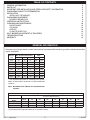
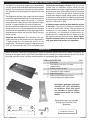
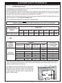
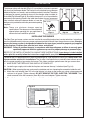
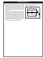
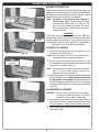
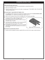
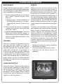
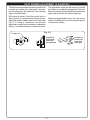
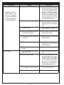
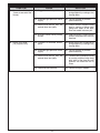
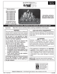
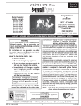
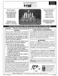
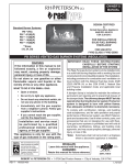
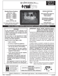
Owner’s
Manual
Design Certified
to:
Z21.84b-2004
Burner Systems:
G45-2-GL-16/19(P)
G45-2-GL-18(P)
G45-2-GL-24(P)
G45-2-GL-30(P)
G45-2-GL-36(P)
G45-2-GL-42(P)
G45-2-GL-48(P)
G45-2-GL-60(P)
(16/19" - 30" models)
FOR INSTALLATION IN
SOLID-FUEL BURNING
FIREPLACES*
FOR USE WITH
GLASS/GEMS
G45-2-GL SERIES VENTED GAS BURNER SYSTEMS (UNREGULATED)
IMPORTANT: READ THESE INSTRUCTIONS
CAREFULLY BEFORE STARTING
INSTALLATION OF THE SYSTEM.
WARNING
If the information in this manual is not
followed exactly, a fire or explosion may
result, causing property damage, personal
injury, or loss of life.
The Real-Fyre gas burner system is to be installed only
in a solid-fuel burning fireplace with a working flue and
constructed of noncombustible material.The installation,
including provisions for combustion and ventilation air
must conform with the National Fuel Gas Code, ANSI
Z223.1/NFPA 54, or the CSA B149.1, Natural Gas
and Propane Installation Code, and applicable local
building codes.
A damper clamp is included to maintain the minimum
permanent vent opening and to prevent full closure of
the damper blade. The chimney damper MUST be fully
opened when burning the burner system.The burner
system is designed to burn with yellow flames;
thus adequate ventilation is absolutely necessary.
To comply with certification, listings, and building
code acceptances, and for safe operation and proper
performance of this burner system, use ONLY Peterson
parts and accessories. Use of other controls, parts, and
accessories that are not designed for use with RealFyre gas burner systems is prohibited and will void all
warranties, certifications, listings, and building code
approvals, and may cause property damage, personal
injury, or loss of life.
*Note: Solid-fuels shall not be burned in a fireplace
where a decorative appliance is installed.
Do not store or use gasoline or other
flammable vapors and liquids in the vicinity
of this or any other appliance.
WHAT TO DO IF YOU SMELL GAS:
• Open a window.
• Do not try to light any appliance.
• Do not touch any electrical switch; do
not use any phone in the building.
• Immediately call the gas supplier
from a neighbor’s phone. Follow gas
supplier’s instructions.
• If you cannot reach the gas supplier,
call the fire department.
Installation and service must be
performed by a qualified professional
installer, service agency, or the gas
supplier.
This appliance is only for use with the
type of gas indicated on the rating plate.
INSTALLER:
Leave this manual with the appliance.
CONSUMER:
Retain this manual for future reference.
Robert H. Peterson Co. • 14724 East Proctor Avenue • City of Industry, CA 91746
REV 1 - 1009220843
1
L-A2-265
TABLE OF CONTENTS
GENERAL INFORMATION
PARTS LIST
IMPORTANT PRE-INSTALLATION AND FIREPLACE SAFETY INFORMATION
GLASS/GEMS QUANTITY DETERMINATION
INSTALLATION
INSTALLING THE BURNER
GLASS/GEMS PLACEMENT
BURNER PREPARATION
OPERATING INSTRUCTIONS
CLEANING AND MAINTENANCE
MAINTENANCE
CLEANING
SERVICE
FLAME DESCRIPTION
PILOT BURNER ADJUSTMENT (IF EQUIPPED)
TROUBLESHOOTING
WARRANTY
2
3
4
5
6
6
8
8
9
10
10
10
10
10
11
12
14
GENERAL INFORMATION
Keep the area of the gas burner system clear and free from combustible materials, gasoline, and other flammable
vapors and liquids.
Burner
size
Min. Fireplace Dimensions
BTU
Width*
Depth
Height
NAT.
L.P.
16/19"
25"
12"
18"
45k
35k
18"
26"
12"
18"
65k
60k
24"
30"
12"
18"
75k
65k
30"
36"
12"
18"
80k
70k
[36"]
42"
12"
18"
120k
110k
[42"]
48"
12"
18"
130k
120k
[48"]
54"
12"
18"
150k
130k
[60"]
66"
12"
18"
170k
140k
* This required width allows for centering of the system.
Add 4" to front width if the burner is to be installed with
a pilot kit.
Note: Bracketed sizes indicate non-certified burner
systems.
Minimum Free Opening Area of Chimney Damper for Venting (sq. in.)
For Factory-Built Fireplaces *
Chimney
Height
15' (min.)
20'
30'
16/19"
18"
24"
30"
36"
42"
48"
60"
28
26
23
41
37
33
47
42
38
50
45
40
75
68
61
82
73
66
94
85
76
107
96
86
* For Masonry-Built Fireplaces; add 4 sq. in. to amount shown.
REV 1 - 1009220843
2
L-A2-265
GENERAL INFORMATION (Cont.)
The Real-Fyre® gas burner system is to be installed only
in a fully vented, noncombustible fireplace with an open
damper. The chimney must be free of any obstructions.
The fireplace must be designed and approved to burn
wood.
Testing the Gas-Supply System: The gas burner
system and its individual shutoff valve must be
disconnected from the gas-supply piping system while
performing any tests of the piping system at pressures
in excess of 1/2 psig. The gas burner system must be
isolated from the gas-supply piping system by closing
its individual manual shutoff valve during any pressure
testing of the gas-supply piping system at test pressures
equal to or less than 1/2 psig.
The fireplace must have a gas-supply line that has been
installed by a qualified technician in accordance with all
local codes. The gas-supply line must be 1/2" minimum
interior diameter. If the gas line to the fireplace is longer
than 20', a larger-diameter line may be necessary.
A fireplace screen must be in place when the system
is burning. Provisions for adequate combustion
air must be maintained. Unless other provisions for
combustion air are provided, the screen shall have
an opening(s) for introduction of combustion air.
Combustion air is adequate when all flames curl into
the fireplace and away from the screen. When a glass
fireplace enclosure (door) is used, leave the doors
fully open when the system is in operation.
Be sure to clean the fireplace floor of any ashes or other
foreign materials. It is recommended that the fireplace
and chimney be inspected by a chimney sweep or other
qualified person before you install the Real-Fyre® gas
burner system.
Required Gas Pressure: The minimum inlet gassupply pressure for the purpose of input adjustment is
7" water column (w.c.) for natural gas and 11" w.c. for
propane gas. The maximum inlet gas-supply pressure is
10.5" w.c. for natural gas and 13" w.c. for propane gas.
PARTS LIST
Before installation, check that your gas burner system is complete. See the PARTS LIST below. If any parts are
missing or damaged, contact your Real-Fyre® dealer before installing or using the burner. Be sure you know
the model and size of your set when ordering options or replacement parts and accessories.
ITEM No. DESCRIPTION
1. Burner pan
Fuel injector (nat. only) / air mixer
2.
(propane only)
1
3.
4.
5.
2
6.
QTY
1
Damper clamp with bolt
Connector kit (with adapters)
Separation grating
Select sand granules (nat. only) or
vermiculite granules (propane only)
1
1
1
1
1
Glass/gems packaged separately.
Quantity will vary, depending
on selection. Glass and gems
are available in various colors;
contact your dealer for further
details.
5
6
Replacement parts are available
through your local Real-Fyre®
dealership.
4A
4B
4C
(PHOTOS NOT TO SCALE)
3
REV 1 - 1009220843
3
L-A2-265
IMPORTANT PRE-INSTALLATION AND FIREPLACE SAFETY INFORMATION
CAUTION: Installation and repair must be done by an NFI Certified or other qualified professional
installer.
Installer:
Carefully read these instructions before installing this gas burner system. Be sure you understand
all safety precautions and warnings contained in this manual.
A. This appliance is designed as an attended appliance. Adults must be present when this gas appliance is operating.
Do not leave this unit burning when unattended or while anyone is sleeping.
B. This appliance is only for use with the type of gas indicated on the rating plate. This appliance is NOT FIELD
CONVERTIBLE for use with other gasses.
C. BE CAREFUL: If not installed, serviced, and used correctly per these instructions, this product can cause
serious personal injury, property damage, or loss of life.
D. WARNING: Before installing in a solid-fuel-burning fireplace, the chimney flue, damper, and firebox must be
thoroughly CLEANED of soot, creosote, ashes, and loose paint, and must be inspected by a qualified chimney
cleaner. Some older fireplaces may need repair prior to installing this appliance.
E. CHECK GAS TYPE (natural or propane): The gas supply must be the same as stated on your burner system rating
plate. If gas supply is different, DO NOT INSTALL. Contact your dealer for immediate assistance.
F. Keep the area of the gas burner system clear and free from combustible materials, gasoline, and other flammable
vapors and liquids.
G. INSUFFICIENT GAS PRESSURE WILL KEEP THE PILOT (IF EQUIPPED) FROM OPERATING PROPERLY. DO NOT
USE IF GAS PRESSURE IS LOWER THAN THE MINIMUM REQUIREMENT.
7" water column (w.c.) on natural gas
H. The minimum inlet gas-supply pressure for purposes of input adjustment is 5"
and 11" w.c. on propane gas. Insufficient gas pressure will affect proper operation of the pilot (if equipped). Do not
install this gas appliance if minimum pressure is not available. The maximum inlet gas-supply pressure is 10.5" w.c.
on natural gas and 13" w.c. on propane gas. The propane source must be regulated. (Do not connect this appliance
directly to an unregulated propane gas tank - this can cause an explosion.)
I.
The gas piping system must be sized to provide minimum inlet pressure at the maximum flow rate (BTU/hr). Undue
pressure loss will occur if the pipe is too small, or the run is too long. Gas supply pipe must be 1/2" minimum interior
diameter. If the gas line is longer than 20', a larger diameter line may be necessary.
J. Input ratings shown in BTU per hour are for elevations up to 2,000 ft. For elevations above 2,000 ft., refer to the National
Fuel Gas Code or contact manufacturer before installing this product.
K. This gas appliance and its main gas valve must be disconnected from the gas-supply piping system during any pressure
testing of that system at test pressures in excess of 1/2 psig.
L. This gas appliance must be isolated from the gas-supply piping system by closing the equipment shutoff valve connected
to the gas-supply line during any pressure testing of the gas-supply piping system at test pressures equal to or less
than 1/2 psig.
M. Do not use this appliance if any part has been underwater. Immediately call a qualified service technician to inspect the
appliance and to replace any part of the control system and any gas control that has been underwater.
N. A fireplace screen must be in place when the system is burning. Provisions for adequate combustion air must be
maintained. Unless other provisions for combustion air are provided, the screen shall have an opening(s) for introduction
of combustion air. Combustion air is adequate when all flames curl into the fireplace and away from the screen. When
a glass fireplace enclosure (door) is used, leave the doors fully open when the system is in operation.
O. This appliance may be installed in an aftermarket, permanently located, manufactured (mobile) home, where not prohibited
by local codes. Installation of appliances designed for manufactured home (U.S. only) or mobile home installation must
conform with the Standard CAN/CSA Z240 MH, Mobile Housing, in Canada, or with the Manufactured Home Construction
and Safety Standard, Title 24 CFR, Part 3280, in the United States, or when such a standard is not applicable, ANSI/
NCSBCS A225.1/NFPA 501A, Manufactured Home Installations Standard.
4
GLASS/GEMS QUANTITY DETERMINATION
CAUTION: Sand granules are for use with natural gas systems only. Always use vermiculite granules
for propane gas systems.
The granules that come with the burner system are pre-measured and must be used per these instructions
(see GLASS/GEMS PLACEMENT section).
Decorative glass/gems (purchased separately) must be placed to cover the burner (but not on the valve or
pilot, if equipped). See Table 5-1 for the minimum bag requirement depending on your burner size. Additional
glass/gems may be purchased and placed around the burner if desired.
Should you wish to fill the entire fireplace floor with glass/gems; instead use Table 5-2 to determine how many
bags of glass/gems to order based on fireplace size.
One 10-lb. bag of glass/gems fills approximately 144 cubic inches.
CAUTION: When covering the burner with glass/gems; do not exceed 1" above the top of the burner.
Additional glass/gems directly on top of the burner may result in unsafe ignition.
Minimum burner
coverage requirement
Table 5-1
Glass/gems
10 lb. bag(s) needed
Burner size
16/19
18
24
30
36
42
48
60
1
2
2
2
4
4
4
5
- OR Fireplace
complete
coverage
Table 5-2
Fireplace
Opening size
28"
36"
Standard
Fireplace Sizes 32" see-thru
42"
50"
Center
width (in.)
Front to back
depth (in.)
Area
(sq. in.)
Glass/gems
10 lb. bags needed
for 2" depth
25
16
400
6
540
8
30
23
690
10
31
23
713
10
36
30
828
12
1085
15
1334
19
46
33
These bag quantities listed allow for an approximate 2" depth of glass in the entire fireplace floor, without a
burner. (The volume of the burner will take up some space, allowing for some excess glass to be used as
desired, or stored as extra for later use.)
Your fireplace area can be determined by measuring the
center width of your fireplace in inches and multiplying by
the depth from front to back in inches. You can then use
the area column in the table above to approximate the
number of bags needed.
Height
Width
Depth
5
INSTALLATION
The damper clamp with hex bolt (Fig. 6-1) is provided as a means to prevent
full closure of the damper blade. The clamp is easily attached to most damper
blades with pliers or a wrench, and must be permanently installed. The clamp
is designed to prevent accidental closure of the damper when installed as
illustrated (Fig. 6-2 and Fig. 6-3). Should the clamp not fit, or fail to provide the
permanent vent opening listed in the table found above, have a permanent
stop installed, remove the damper blade, or have the
damper cut to provide the minimum permanent opening Set screw
required.
Note: T h e s e a r e m i n i mu m d a m p e r o p e n i n g
specifications. The damper must be completely
opened when operating this gas appliance to
achieve the best ventilation possible.
Damper clamp
Fig. 6-1
Open
Closed
Fig. 6-2
Fig. 6-3
INSTALLING THE BURNER
The Real-Fyre gas burner system must be installed by a qualified professional service technician. Instructions
must be followed carefully to ensure proper performance and full benefit from the gas burner system. Check to
be sure the burner system is designed and labeled for the type of gas (natural or propane gas) supplied
to the fireplace. Fireplace floor must be level, clean, and smooth.
WARNING: Failure to position the parts in accordance with these diagrams or failure to use only parts
specifically approved with this appliance may result in property damage or personal injury.
REFER TO THE PARTS LIST WHEN FOLLOWING THESE INSTRUCTIONS. If your burner is to be installed
with a pilot kit; carefully follow the instructions supplied with your pilot kit for specific gas connection.
The burner pan is supplied with an air mixer for propane gas or a fuel injector for natural gas. The air mixer / fuel
injector must be used in ALL installations. The air mixer / fuel injector has a precisely sized orifice to ensure
only the proper quantity of gas enters the burner. This allows maximum performance and gas conservation.
1. MAKE SURE THE FIREPLACE GAS SUPPLY IS TURNED OFF.
2. Locate the gas-supply stub inside the fireplace and remove the cap, if attached (see Fig. 6-4).
CAUTION: When removing the cap, make sure the stub does not turn, loosening the connection inside the wall.
3. Attach the small adapter (Item 4C) to the fuel injector / air mixer on the burner pan, using a pipe compound
resistant to all gases. Tighten securely. DO NOT REMOVE THE FUEL INJECTOR / AIR MIXER. Then
attach one end of the flex connector (Item 4B) to the small adapter. Tighten securely.
4. Place the burner system into the fireplace so that it is centered
centered.and the open burner pan faces outward.
Fig. 6-4
Gas line
cap
Gas supply
line stub
6
INSTALLATION (cont.)
5. Be sure gas to the fireplace is off. Attach the large
adapter (Item 4A) to the gas-supply stub using a pipe
compound resistant to all gases. Tighten securely. Then
attach the open end of the flex connector to the large
adapter. Tighten securely. Ensure the pan rests level
on the fireplace floor after connection. Adjust the pan if
necessary.
6. LEAK TEST: Use a long-necked butane lighter, or lay
a lighted match next to the burner pipe, and carefully
turn on the gas supply until the burner ignites. Test at
all connections for leaks using the appropriate soapy
water solution. If bubbles appear, a leak is present. Turn
off the gas and tighten at all connections. Repeat until
no leaks are present. If a leak persists, turn off the gas
supply and contact the local gas company or dealer.
NEVER USE A FLAME TO CHECK FOR LEAKS.
Turn off the gas supply prior to proceeding.
7
Fig. 7-1 - Fireplace valve
Fuel injector / air mixer
Burner pan
Flex
connector
Large
Adapter
Small
adapter
Gas
supply stub
GLASS/GEMS PLACEMENT
BURNER PREPARATION
Burner pan
Granules up
to burner
tube
After hooking up the burner to the fireplace gas supply and
placing the heat shield on the valve assembly (if applicable),
the decorative media (granules and glass/gems) must be
added for the burner to function as designed.
Note: Installation is the same for glass and gems.
Glass shown here. These instructions show
sand granules being used as a base for the
glass, but only natural-gas burners use sand.
For propane burners, follow these instructions
using vermiculite.
Fig. 8-1
Separation
grating
WARNING
The burner and pilot (if equipped) must be OFF (fully
extinguished), and all valve covers must be in place before
pouring media onto the burner. It may also be necessary
to temporarily cover the pilot assembly (if equipped) to
keep media out of it during this procedure.
GRANULE PLACEMENT
Fig. 8-2
1. Partially fill the burner pan with the granules*, up to
the burner tube (see Fig. 8-1).
*Note: Use only select sand for natural gas burners
and vermiculite for propane gas burners.
2. Place the separation grating over the granules so that
the angled parts
hook over
and back of the
part hooks
overthe
thefront
top and
burner pan, as shown in Fig. 8-2.
Granules sloped to
burner pan
Note: The grating must correctly rest onto the burner
pan. If it sits too high; remove some of the
granules to ensure a proper fit.
Fig. 8-3
3. Pour the remainder of the granules onto the separation
grating, filling the pan. Avoid spilling the granules
on the pilot kit (if equipped). Slope the granules at
the same angle as the burner pan. This is important
to ensure quiet lighting and even flame distribution
(Fig. 8-3).
GLASS/GEMS PLACEMENT
CAUTION: Glass pieces may have sharp edges.
Be careful handling the glass. Use hand
protection, such as gloves, if necessary.
Fig. 8-4
1. Pour the glass/gems directly on top of the granules so
that the burner pan is covered completely and evenly.
Do not exceed a 1" depth directly above the burner.
2. AddAt
additional
around
theas
burner
pan as
Note:
this stageglass/gems
the burner will
function
designed;
desired
(Fig.
8-4).
however, more glass/gems may be added
around the burner for decorative purposes. If
glass/gems are desired behind the burner pan,
they may be left at a lower level than the back
of the pan, as shown in Fig. 8-5, or raised up
to or above the level in the back of the pan.
2. Add additional glass/gems around the burner pan as
desired (Fig. 8-5).
8
OPERATING INSTRUCTIONS
Before operating your gas log set:
1. Be sure your fireplace is free from flammable liquids or combustible materials.
2. Be sure your damper is open.
3. Smell all around the gas log set for the odor of escaping gas. IF YOU SMELL GAS, FOLLOW THE
INSTRUCTIONS ON P. 1.
If your gas log set is operated by the fireplace valve:
1. Lay a lighted long-stem match on the surface of the embers near the gas inlet (do not hold the match
in your hand) or use a lighted long-necked butane lighter (Fig. 9-1).
2. Slowly turn the fireplace remote valve to the ON position. Your log set should light.
3. If the log set does not light before the match goes out,
immediately turn the valve to the OFF position.
4. Wait approximately five (5) minutes to clear out any gas,
and repeat steps 1-3 above.
5. If your log set fails to light again, turn the valve to the OFF
position and contact your dealer or gas supplier.
6. To extinguish your gas log set, turn the valve to the OFF
position. Be sure the valve is turned fully off to avoid any
gas leakage.
Fig. 9-1
Apply match - then turn on gas
If your burner is operated by a pilot kit:
1. Carefully follow the lighting instructions supplied with your pilot kit for the steps to ignite the burner.
9
CLEANING AND MAINTENANCE
MAINTENANCE
SERVICE
Once installed and operating properly, your RealFyre® glass burner will require regular maintenance.
You should inspect your glass burner and controls
(where installed) for the following:
While some minor service conditions can be
handled by the owner of the glass burner, a
qualified professional service technician should
be called to maintain and service your glass
burner and any installed control systems. In
addition, a periodic examination and cleaning of
the solid-fuel-burning fireplace venting system
should be conducted by a qualified professional
service technician. The TROUBLESHOOTING
section of these instructions serves as a guide
for ensuring optimum performance of your glass
burner.
1. Moisture may cause the glass in your burner
pan to settle. To improve the burn, follow
these tips:
a. Settling of glass - Using a screwdriver or
flat-blade knife, carefully stir the glass,
loosening the material. Clear up any
spills.
2. Debris around the control (if equipped)
-Inspect control and pilot to be sure they are
free of dirt or debris.
To protect your investment in your Real-Fyre®
gas fireplace burner system and keep it operating
safely for years to come, maintain, clean, and
inspect it regularly. We recommend following
these instructions at the beginning of each
fireplace season and as needed throughout the
year, depending on your usage pattern and the
environmental conditions in your home. More
frequent cleaning and maintenance may be
necessary when burning propane gas than with
natural gas.
3. Insects and burner blockage - Check the
burner ports and air shutter, if present, to
make sure they are free from debris. Blocked
burner ports and orifices may result in a fire
at the air shutter.
CLEANING
The pilot assembly (if equipped) must be
kept clean and clear of debris at all times for
the fireplace burner system to be safely and
effectively operated. Dust, carpet fibers, paper,
spider webs, pet hair, etc. in the fireplace or
on the burner assembly can affect operation
of burner and pilot assembly. Vacuum or use
compressed air from a can or compressor to
clean out pilot assembly area, air shutter holes,
burner orifices, and pilot air intake openings.
Blockage in this area will affect the operation of
pilot assembly.
• Replace all batteries for remote transmitters
and receivers if installed.
• Check and readjust the burner air shutter.
• Clean and test the ignitor and pilot (if
equipped).
FLAME DESCRIPTION
Observe the flames. The flames should be blue
at the base and a combination of blue/yellow at
the body and tips. The flames should be 16" to
18" tall. (See Figure 10-1). Inspect the flames
periodically. If flames appear different, contact
a professional service technician or your gas
supplier to correct the problem.
Fig. 10-1
10
PILOT BURNER ADJUSTMENT (IF EQUIPPED)
The pilot burner is preset at the factory and should
normally not require any adjustment. However,
should adjustment be necessary, the following
steps should be taken:
With the pilot burner lit and the control knob in
the pilot position, remove the heatshield covers.
Adjust the screw located on the control valve (see
Fig. 11-1). Using a screwdriver, turn the pilot
adjustment screw slowly clockwise to reduce the
flame, or counterclockwise to increase the flame.
PilotPILOT
adjustment
The adjustment screw can be turned so that the
pilot flame is completely extinguished. The pilot
flame should be a quiet soft blue flame with yellow
tipping that encircles the thermocouple tip.
Replace the heatshield covers. Turn the control
knob to the ON position to assure proper ignition
of the burner system.
Fig. 11-1
ADJUSTMENT
Example of
burner pilot
flame with
thermocouple
11
Example of
burner pilot
flame with
thermopile
TROUBLESHOOTING
SYMPTOM
1. Smoking and/or sooting
CAUSE
A. Poor draft or downdraft
A. Check for chimney blockage.
Be sure chimney is at least
3' taller than anything within
10' of it in all directions. If not,
consult a chimney sweep.
Chimney cap or fan may help.
Under severe conditions, you
may need to open a window
near the fireplace about 1" to
2" when burning the unit.
B. Improper burner for gas used
B. Use only a natural-gas set
with natural gas or use only a
propane-gas set with propane
gas.
C. Damper closed
C. Open damper fully when
operating burner system.
D. Burner is positioned too close to
the front of the firebox
D. Move burner system to the
center of the firebox.
E. Improper glass/gems placement
or amount
E. See PLACEMENT OF GLASS/
GEMS section.
F. Flue is less than 8" in diameter
F. I n a d e q u a t e f i r e p l a c e
ventilation; consult with a
fireplace expert.
G. Air mixer on propane set is
closed
G. Open air mixer completely.
A. Incorrect decorative media for
type of gas used
A. Consult your dealer for proper
set.
B. Insufficient gas supply
B. Other gas appliances may
be competing for gas supply.
Consult installer or plumber.
Orifice size is based upon
7" w.c. pressure for natural
gas and 11" w.c. pressure for
propane gas. Plumbing must
supply adequate pressure.
C. Blockage or kink in connector
kit, plumbing, or burner orifice
C. Clean out blockage. If connector
kit is kinked, replace it.
D. Valve not fully open
D. Open valve fully.
( I M M E D I AT E LY
STOP USING. Call
your gas supplier
or another qualified
professional installer
or service agency.)
2. Low flame
SOLUTION
12
TROUBLESHOOTING (cont.)
SYMPTOM
3. Uneven flame distribution
(Lower at one end of the
burner)
4. Flame at air mixer
(For propane units)
CAUSE
SOLUTION
A. Clogged or blocked portholes
A. Burner ports can be cleared of
foreign objects by running a wire
through them.
B. Insufficient gas pressure and/or
supply
B. Consult installer or plumber
(see solution 2B).
C. Decorative media may be
packed down too tightly
C. Loosen media around burner
pipe by running a kitchen knife
along both sides of the pipe.
Even out media in burner pan.
D. Auxiliary shutoff valve partially
closed
D. Open valve fully. Usually you will
find this along the wall 3' from the
fireplace.
A. Clogged or blocked burner
ports
A. Burner ports can be cleared of
foreign objects by running a wire
through them.
B. Insufficient gas pressure and/or
supply
B. Consult installer or plumber
(see solution 2b).
C. Decorative media may be
packed down too tightly
C. Loosen media around the burner
by running a kitchen knife along
both sides of the pipe. Be sure
granules are used with an air
mixer.
D. Excessive gas pressure
D. Contact your gas supplier.
13
WARRANTY
PETERSON VENTED DECORATIVE GAS APPLIANCE
LIMITED WARRANTY
All Peterson burner assemblies are WARRANTED for TEN (10) YEARS.
All Peterson glass is WARRANTED for TEN (10) YEARS.
SPK-26 controls are covered by a THREE (3) YEAR “All Parts” Warranty.
All other Peterson valves, pilots, and controls are covered by a ONE (1) YEAR Limited Warranty (excluding batteries).
PLEASE KEEP A COPY OF YOUR SALES SLIP FOR PROOF OF PURCHASE
This warranty applies to the original purchaser and to single family residential use only. It commences from date of purchase, and is valid only with
proof of purchase.
This warranty does not cover parts becoming defective through misuse, accidental damage, electrical damage, improper handling, storage, and/or
installation. Product must be installed (and gas must be connected) as specified in the instructions or operator’s manual, by a qualified professional
installer. Accessories, parts, valves, remotes, etc., when used must be Peterson Co. product.
This warranty does not apply to rust, corrosion, oxidation, or discoloration, unless the affected component becomes inoperable. It does not cover
labor or labor-related charges.
This warranty specifically excludes liability for indirect, incidental, or consequential damages. Some states do not allow the exclusion or limitation of
incidental or consequential damages, so the above exclusion may not apply to you. This warranty gives you specified legal rights, and you may have
other rights that may vary from state to state.
For additional information regarding this warranty, or to place a warranty claim, contact the R.H. Peterson dealer where the product was purchased.
TO REGISTER YOUR PRODUCT ONLINE GO TO: WWW.RHPETERSON.COM,
AND CLICK ON PRODUCT REGISTRATION. THANK YOU FOR YOUR PURCHASE.
Robert H. Peterson Co. • 14724 East Proctor Avenue • City of Industry, CA 91746
14