1
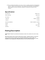
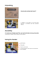
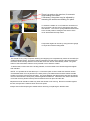
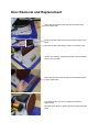
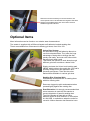
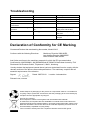
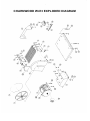
12” DISC SANDER
OPERATORS MANUAL
MODEL: W413
Charnwood, Cedar Court, Walker Road,
Hilltop Industrial Estate, Bardon Hill, Leicestershire, LE67 1TU
Tel. 01530 516 926 Fax. 01530 516 929
email: [email protected] website: www.charnwood.net
GENERAL SAFETY RULES
WARNING: Do not attempt to operate the machine until you have read thoroughly and
understood completely all instructions, rules, etc. contained in this manual. Failure to comply
may result in accidents involving fire, electric shock, or serious personal injury. Keep this
owner's manual and review frequently for continuous safe operation.
1. Know your machine. For your own safety, read the owner's manual carefully.
Learn its application and limitations, as well as specific potential hazards
pertinent to this machine.
2. Make sure all tools are properly earthed.
3. Keep guards in place and in working order. If a guard must be removed for
maintenance or cleaning, make sure it is properly replaced before using the
machine again.
4. Remove adjusting keys and spanners. Form a habit of checking to see that
the keys and adjusting spanners are removed from the machine before
switched it on.
5. Keep your work area clean. Cluttered areas and workbenches increase the
chance of an accident.
6. Do not use in dangerous environments. Do not use power tools in damp or
wet locations, or expose them to rain. Keep work areas well illuminated.
7. Keep children away. All visitors should be kept a safe distance from the
work area.
8. Make workshop childproof. Use padlocks, master switches and remove
starter keys.
9. Do not force the machine. It will do the job better and be safer at the rate
for which it is designed.
10. Use the right tools. Do not force the machine or attachments to do a job for
which they are not designed. Contact the manufacturer or distributor if there is
any question about the machine's suitability for a particular task.
11. Wear proper apparel. Avoid loose clothing, gloves, ties, rings, bracelets, and
jewellery which could get caught in moving parts. Non-slip footwear is
recommended. Wear protective hair covering to contain long hair.
12. Always use safety glasses. Normal spectacles only have impact resistant lenses.
They are not safety glasses.
13. Do not over-reach. Keep proper footing and balance at all times.
14. Maintain the machine in good condition. Keep the machine clean for best and safest
performance. Follow instructions for lubrication and changing accessories.
15. Disconnect the machine from power source before servicing and when
changing the blade.
16. Never leave the machine running unattended. Turn the power off. Do not leave the
machine until it comes to a complete stop.
17. Do not use any power tools while under the effects of drugs, alcohol or medication.
18. Always wear a face or dust mask if operation creates a lot of dust and/or chips.
Always operate the tool in a well ventilated area and provide for proper dust removal.
Use a suitable dust extractor.
ADDITIONAL RULES FOR SANDERS
1. This machine is designed for use with wood and plywood. Sanding metal, plastics
and MDF will result in damage to the abrasive disc, fire risk and/or potential health
hazards.
2. The sander is designed for indoor use only.
3. Never use the machine unless it is connected to a dust extraction system, which
should be started prior to sanding and left to run for a few moments after the job has
been finished. .
4. The sander should be bolted to a bench or suitable stand.
5. Always hold the work firmly on to the table.
6. Never use the sander with the disc cover, guard and/or dust hood removed.
7. Dot not wear gloves or hold the workpiece with a rag. There is a risk that leather or
fabric might get caught between the disc and the edge of the table. This could result
in personal injury and/or damage to the machine.
8. Sand with the grain.
9. If sanding the end of a long piece of timber, provide additional support at the same
height as the table.
10. Switch the machine off before removing debris from the table.
11. Switch the machine off before changing the table angle.
12. Disconnect the sander from the mains before changing the abrasive disc.
13. Do not operate the sander if the abrasive disc is torn, otherwise damaged or loose.
14. Always wear eye protection when sanding.
15. Do not modify this machine in any way or use it or anything other than its designated
purpose. Neither the manufacturer nor the suppliers will be liable for any damage or
injury caused by incorrect assembly, operation or electrical connection of this
machine.
Specification
Disc diameter
Motor (induction)
Disc speed
Table size
Table tilt
Dimensions (WxDxH)
305mm (12")
750w (1hp)
1450rpm
395mm x 295mm
- 10 to 45
450mm x 550mm x 400mm
Weight
30kg
Rating
Light Trade
Warranty
1 Year
Rating Description
Light Trade: Suitable for professional woodworkers where the machine will not be in daily
use.
Mid range machines with a heavier build and more power. Typically used by 2 or 3 people
within a small business and also for the dedicated hobbyist with a larger budget. It is
expected to be used up to the machines maximum limit with occasional long work periods.
Suitable for income generation. Expected maximum use of 300 hours annually.
Unpacking
Open the carton, carefully unpack all of the
contents and lift the sander onto a bench.
In addition to the sander you will find three
spanners, a screwdriver and this instruction
manual.
Assembly
This machine is supplied fully assembled. It is recommended that you bolt or screw it down
to a work bench or suitable stand. The 63mm port at the back of the sander should be
connected to a suitable vacuum system or dust extractor.
Using the Sander
On/Off switch
Tilting table
T-slot for mitre fence
Tilt locking handle - there is also one at the other
end of the table.
There is a scale on the trunnion, for accurate
angle setting of the table.
If necessary, the pointer may be adjusted by
loosening the small screw holding it in place.
To switch the sander on or off, slide the red section of
the cover back. Lift the cover to expose the stop and
start buttons. The cover is spring loaded and will return
to the closed position. Hitting the red section of the
cover will activate the stop button.
Compound angles can be set by using the mitre gauge
in conjunction with the tilting table.
This sander is very easy to operate. Starting and stopping is accomplished by means of the NVR (No
Voltage Release) switch. This type of switch is designed so that if the machine is disconnected from
the mains whilst running and then reconnected, the motor will not automatically restart. The green
button of the NVR switch will have to be pressed once to start the sander.
To tilt the table, loosen both of the locking handles, move the table to the desired angle and tighten
both handles.
NOTE: It is possible to set the table up to -10° but this option must be used with extreme caution.
Considerable down force is placed on the work piece by the abrasive disc and this makes it a little
harder to move the wood across the table. The angle between the table and the disc also increases
the force with which the work piece presses against the abrasive. Should the disc start to slow down
more than normal, please reduce pressure between the work piece and the disc.
Adjustments to tilt should be made only when the sander is not running. Never force timber against
the disc, always let the machine work at its own speed.
Always switch off and unplug the sander before removing or replacing the abrasive disc.
Disc Removal and Replacement
There are two bolts securing the dust collection hood,
remove them both.
Remove the two bolts which secure the disc cover to the
base.
Remove the two bolts fixing the disc cover to the motor.
Lift the disc housing, complete with table, off the machine
and set it to one side.
Swing the top of the dust collection hood forward and lift
it clear of the base.
The abrasive disc can now be easily accessed for
replacement.
Reverse these steps to replace the disc housing and dust
hood.
Should it ever be necessary to remove the disc, the
motor spindle can be locked with the largest of the three
spanners provided and the disc unscrewed. It has a
standard right hand thread.
Optional Items
More information can be found on our website www.charnwood.net
The sander is supplied with a 300mm diameter self-adhesive backed sanding disc.
These are available from Charnwood in differing grit sizes, from 60 to 150.
Velcro Disc System
An alternate to using self-adhesive discs is to
use Velcro backed discs. They offer the huge
advantage of being able to change the disc
quickly and easily, and even refit a disc which
has previously been used.
This allows the operator to work down through
different grit sizes to achieve a better finish.
Simply purchase the Velcro hook backing pad,
VB300, which sticks to the metal disc. Our pad is
specially designed for this application and
prevents sponginess. Then use the velour
backed discs available in various grit sizes.
Sanding Disc Cleaning Stick
Dramatically increase the life of sanding discs
with this cleaning stick.
Removes clogged up pitch and sawdust when
pressed lightly against the rotating disc.
Dust Extraction It is strongly recommended that
a dust extractor is used with this sander to
prevent inhalation of harmful sanding dust.
The W413 Sander is fitted with a 63mm
diameter outlet for dust collection. A conversion
kit, W413DE, is available to adapt the outlet for
use with 100mm diameter dust extraction hose.
Troubleshooting
Problem
Machine does not start
Only starts when Green button
is held down
Motor slows down during
operation
Excess Vibration
Cause
Blown Fuse
Loose switch terminal
Faulty switch
Faulty switch
Remedy
Replace Fuse
Inspect back of switch
Replace switch
Replace switch
Attempting to take too heavy a
cut
Rotating parts out of balance
Reduce pressure between the
work piece and the disc
Check the disc plate is tight on
the shaft
Check the disc plate is not
warped
Declaration of Conformity for CE Marking
Charnwood Declare that woodworking disc sander, Model W413
Conforms with the following Directives:
Machinery Directive 2006/42/EC
Low Voltage Directive 2006/95/EC
EMC Directive 2004/108/EC
And further conforms to the machinery example for which the EC type examination
Certificate No. AM 50039981, AN 50039850 and AE 50249743 have been issued by TUV
Rheinland LGA Products GmbH, Tillystrasse 2, 90431, Nurnberg.
I hereby declare that equipment named above has been tested and found to comply with the
relevant sections of the above referenced specifications. The machinery complies with all
essential requirements of the directive.
Signed:
Dated: 30/07/2010
Location: Leicestershire
Richard Cook, Director
Please dispose of packaging for the product in a responsible manner. It is suitable for
recycling. Help to protect the environment, take the packaging to the local amenity tip
and place into the appropriate recycling bin.
Only for EU countries
Do not dispose of electric tools together with household waste material!
In observance of European Directive 2002/96/EC on waste electrical and electronic
equipment (EEE) and its implementation in accordance with national law, electric tools
that have reached the end of their life must be collected separately and returned to an
environmentally compatible recycling facility.
Your local refuse amenity will have a separate collection area for EEE goods
CHARNWOOD W413 EXPLODED DIAGRAM
CHARNWOOD W413 PARTS LIST
Item
01
02
03
04
05
06
07
08
09
10
11
12
13
14
15
16
17
18
19
20
21
22
23
24
Part
Base
Motor base
Motor
n/a
Disc Cover
n/a
Disc
n/a
Abrasive
Rear trunnion
Front trunnion
Table
n/a
Dust Collection Hood
Locking handle
Pointer
Pan head set screw M4 x 8
Spring washer
Pan head set screw M6 x 8
Hex head setscrew M8 x 20
Washer
M8
Hex head set screw M8 x 20
Washer
M8
Nut
M8
QTY
1
1
1
1
1
1
1
1
1
1
1
1
1
6
2
4
14
4
12
8
Item
25
26
27
28
29
30
31
32
33
34
35A
36
37
38
39
40
41
42
43
44
45
46
47
48
49
Part
Hex head set screw M8 x 16
Hex head set screw M6 x 12
Washer
M6
Nut
M6
n/a
Guard
Rd head set screw M5 x 8
Hex head set screw M6 x 10
n/a
Scale
Switch DKLD-6-2
n/a
n/a
n/a
n/a
n/a
Mitre gauge bar
Mitre gauge
Bolt
M6
Pointer
Rd. head set screw M5 x 6
Pin
Hex head set screw M6 x 60
Motor junction box
Capacitor 16UF 450VAC
QTY
2
6
6
6
1
2
2
1
1
1
1
1
1
1
1
4
1
Charnwood, Cedar Court, Walker Road,
Hilltop Industrial Estate, Bardon Hill, Leicestershire, LE67 1TU
Tel. 01530 516 926 Fax. 01530 516 929
email: [email protected] website: www.charnwood.net