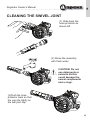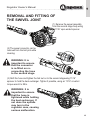
1
US Regulator Owner’s Manual DOC/0258/US ISSUE 9 1 US Regulator Owner’s Manual ............................................................................................ Copyright Notice This owner’s manual is copyrighted, all rights reserved. It may not, in whole or in part, be copied, photocopied, reproduced, translated or reduced to any electronic medium or machine readable form without prior consent in writing from Apeks. ©2012 Apeks Regulator Owner’s Manual Please read the instructions in this manual carefully before using your regulator. Warnings, Cautions and Notes Pay special attention to information provided in warnings, cautions and notes, that is accompanied by these symbols: A WARNING: indicates a procedure or situation that, if not avoided, could result in serious injury or death to the user. A CAUTION: indicates any situation or technique that could cause damage to the product, and could subsequently result in injury to the user. A NOTE: is used to emphasise important points, tips, and reminders. WARNING: This manual provides essential instructions for the proper setup, inspection, use, and care of your new regulator. Because Apeks regulators utilise patented technology, it is very important to take the time to read these instructions in order to understand and fully enjoy the features that are unique to your specific model. Improper use of your regulator could result in serious injury or death. 2 US Regulator Owner’s Manual ............................................................................................ Contents: General Precautions & Warnings............................................................................................4 Introduction...............................................................................................................................5 Enriched Air Nitrox Use (EAN).................................................................................................7 Enriched Air Nitrox Use – Outside EEC (European Economic Community) Countries...7 Enriched Air Nitrox Use – Inside EEC (European Economic Community countries EN 1443-3 and EN13949.................................................................................8 Overview of Features..............................................................................................................10 Second Stage Hose Configuration.................................................................................10 Diver Changeable Exhaust System (DCE)....................................................................11 External Second Stage Adjustments.............................................................................13 Integrated Venturi Switch...............................................................................................13 Inhalation Resistance Control Knob..............................................................................14 Egress Second Stage....................................................................................................15 Status.......................................................................................................................................16 Safety First.....................................................................................................................16 Status Operational LCD Display Sequence...................................................................16 Servicing........................................................................................................................17 Understanding the Status..............................................................................................17 Status Product Range....................................................................................................17 Status Operating Procedure..........................................................................................17 Status Condition Display Guide.....................................................................................18 Cold Water Diving..........................................................................................................19 If the Status Fails to Display..........................................................................................19 Warranty Restriction..............................................................................................................20 First Stage Environmental Protection............................................................................21 Second Stage Cold Water Protection............................................................................21 Auxilliary Emergency Breathing Systems............................................................................22 Preparation and Setup............................................................................................................25 Hose Attachment............................................................................................................25 Hose Fitting Operation For Lightweight 2nd Stages......................................................25 Attaching the First Stage to the Cylinder Valve (Yoke)..................................................27 Attaching the First Stage to the Cylinder Valve (DIN)...................................................28 DIN to Yoke Converter...................................................................................................30 Diving with Your Regulator....................................................................................................31 Pre-Dive Inspection Checklist.........................................................................................31 During the Dive...............................................................................................................32 Diving In Cold Water.......................................................................................................33 After the Dive..........................................................................................................................35 Removal of the Regulator from the Cylinder Valve (DIN)..............................................35 Care & Maintenance.......................................................................................................36 Dealer Service & Repair.................................................................................................38 Cleaning the Swivel Joint......................................................................................................39 Removal of the Swivel Joint...........................................................................................40 Warranty Information.............................................................................................................41 Limited Lifetime Warranty...............................................................................................41 ÉRestrictions.....................................................................................................................42 Returning Your Regulator For Service...........................................................................42 Markings and Abbreviations...........................................................................................43 Notes.........................................................................................................................44-46 Regulator Service Record.........................................................................................................47 3 US Regulator Owner’s Manual ............................................................................................ General Precautions & Warnings • • • • • • • • • efore using this regulator, you must receive instruction and B certification in SCUBA diving from a recognised training agency. Use of SCUBA equipment by uncertified or untrained persons is dangerous and can result in injury or death. This regulator is not configured for commercial use with surface supplied air. Always pressurise the regulator gradually by opening the cylinder valve SLOWLY. U nless instructed, NEVER apply any type of lubricant to any part of the regulator or cylinder valve. DO NOT apply any type of aerosol spray to the regulator. Doing so may cause permanent damage to certain plastic components, including the second stage housing. Factory prescribed service for this regulator must be performed at least once annually by a factory trained Apeks / Aqualung service technician who is employed by an authorised dealer. Disassembly, repair, or first stage adjustment must not be attempted by persons who are not factory trained and authorised by Apeks / Aqualung. DO NOT leave a cylinder standing unsecured with the regulator attached to the valve. Doing so may cause permanent damage to the regulator and cylinder valve if the cylinder falls over. DO NOT carry SCUBA equipment by the first stage when it is connected to a cylinder. Always carry the cylinder by the cylinder valve or an attached carrying device. When diving in cold water (below 10°C, or 50°F), you must have received training and certification in the techniques of cold water diving from a recognised training agency. Correct Selection of specific cold water equipment is required. Any equipment marked with the greater than 10º Celcius symbol; (> 10°C) are only suitable for water temperatures above 10°C or 50°F. • When configuring your regulator for use with emergency auxiliary Breathing systems (Octopus), the correct selection of equipment is required. Any equipment marked with EN250A is suitable for use with an octopus. 4 US Regulator Owner’s Manual ............................................................................................ INTRODUCTION Congratulations—and thank you—for choosing Apeks. All Apeks regulators have been designed and manufactured with pride in the U.K. as part of the Aqualung group of companies, according to standards which meet or surpass all requirements for the BS EN ISO 9001:2000 quality control system. Your Apeks regulator is covered by Apeks’ Limited Lifetime Warranty against defects in materials or workmanship. This warranty is only extended to the original purchaser, and is not transferable. For more information, be sure to read the warranty section of this manual, and remember to save your sales receipts. Copies of these receipts must be presented whenever obtaining warranty service. Perhaps more than any other piece of diving equipment you will own, your regulator’s function and performance relies greatly on the care and maintenance it will receive, in addition to regularly scheduled dealer service. Before you dive with your new Apeks regulator, it is therefore important to read this manual in its entirety to become familiar with its features, as well as the correct procedures for setup, pre-dive inspection, and post-dive maintenance. Please read on to learn how you can obtain the maximum enjoyment from your regulator, and maintain its like-new performance for many years to come. WARNING: Improper use or misuse of SCUBA equipment may result in serious injury or death. Read and understand this owner’s manual completely before diving with your Apeks regulator. NOTE: This product has been examined by Germanischer Lloyd AG, Vorsetzen 32, D-20459 Hamburg, Germany, notified body for PPE Identification number 0098. NOTE: This product meets the requirements as laid out in the European directive relating to Personal Protective Equipment, Council Directive 89/686/EEC modified by Council Directive 86/58/EC. NOTE: All Apeks regulators have been tested and certified in accordance with EN250 : 2000 to a depth of 50 metres. *prEN250:2012 and prEN250:2012 Annex A; Auxilliary Emergency Breathing Systems to a depth of 50 Metres. See further note below. XTX 200, Tek3 and XTX 50 have been tested and certified in accordance with EN250 : 2000 to a depth of 200 metres. 5 US NOTE: EN250:2000 Respiratory equipment – Open Circuit Self Contained Compressed Air Diving Apparatus – Requirements, Testing and Marking is a European normative standard that was published in the year 2000, and Regulators must be independently tested to ensure it meets these minimum requirements. The purpose of this European Standard is to ensure a minimum level of safe operation for apparatus down to a maximum depth of 50 metres (164ft). *prEN250:2012 Respiratory equipment – Open Circuit Self Contained Compressed Air Diving Apparatus – Requirements, Testing and Marking is a preliminary European normative standard that is to be published in 2013, which includes new minimum requirements such as Auxiliary Emergency Breathing Systems, Annex A and will replace EN250:2000. 6 US Regulator Owner’s Manual ............................................................................................ ENRICHED AIR NITROX USE (EAN) WARNING : This chapter contains important information concerning use with oxygen-enriched air (Nitrox/EAN). Do not attempt to use this product with enriched air without having entirely read and understood this chapter. If you do not do this, you risk serious injury or death. WARNING : Obtain Nitrox Diving Certification. In order to gain a complete appreciation of the advantages of diving with Nitrox, it is ABSOLUTELY NECESSARY that you undergo special training and obtain certification in Nitrox diving from a recognised training agency. The depth and time limit of the dive depends on the oxygen content of the Nitrox mixture. WARNING: The maximum operating depth of your regulator and exposure times are dependent on the oxygen content of the gas you are using. Enriched Air Nitrox Use – Outside EEC (European Economic Community) Countries Your Apeks regulator has been prepared for use with Enriched Air Nitrox (EAN) where the percentage of oxygen in the EAN does not exceed 40%. This is possible because each regulator is built to a high standard of cleanliness using EAN compatible components and lubricants. In addition, each regulator design has passed stringent adiabatic compression testing to ensure its safety and compatibility with increased percentages of oxygen. If it is your intention to use your new Apeks regulator with Nitrox EAN (O2 not to exceed 40%), it is imperative that you maintain the internal cleanliness of the regulator (see section on Care and Maintenance). If it is your intention to use the regulator interchangeably with breathing air, the breathing air should be oxygen-compatible or “hyperfiltered” where the condensed hydrocarbons do not exceed 0.1 mg/m3. Your local authorised Apeks dealer can help you determine whether the breathing air that they provide meets this criterion. 7 US Regulator Owner’s Manual ............................................................................................ Standard compressed breathing air meeting the EN 12021 standard, often referred to as Grade E in the United States, does not necessarily meet this criterion. Grade E or EN 12021 breathing air may contain a certain level of hydrocarbons, including traces of compressor oils that while not considered harmful to breathe, can pose a risk in the presence of elevated oxygen content. Passing hydrocarbons through a valve and regulator creates a cumulative effect where the hydrocarbons build up over time along the internal passageways of the equipment. When these hydrocarbons come into contact with high-pressure oxygen enriched air, they can pose a very real hazard that can lead to combustion. Therefore, if a regulator has had use with Grade E or EN 12021 breathing air, it should be returned to an authorised Apeks dealer for overhaul service including oxygen cleaning, prior to being put back into nitrox service. Although second stage components are not exposed to high pressure EAN, Apeks recommends that the same cleaning procedures be followed for the complete regulator. This prevents the possibility of cross contamination and guarantees the cleanliness of the entire regulator. Enriched Air Nitrox Use – Inside EEC (European Economic Community ) countries EN 1443-3 and EN13949 In CEE countries, diving with Nitrox/O2 is controlled by Standards EN 144-3 – Respiratory protective devices - Gas cylinder valves - Part 3: Outlet connections for diving gases Nitrox and oxygen - and EN 13949 – Respiratory equipment - Open circuit self-contained diving apparatus for use with compressed Nitrox and oxygen - requirements, testing, marking. NOTE : The maximum depth of the dive is determined by the type of mixture used. NOTE : Apeks offers a range of regulators designed and manufactured specially for use with oxygen-enriched mixtures, over 21% and up to 100% oxygen. This range has been certified according to the EN 144-3 and EN 13949 standards and meets the requirements of the adiabatic compression tests. They have received CE certification for this type. For further information on this range, contact your Apeks / Aqualung specialist centre. 8 US Regulator Owner’s Manual ............................................................................................ WARNING : These regulators fitted with special connections should be used only with complementary equipment (tank valves, tanks, pressure gauges, etc.) designed and prepared for use with an oxygen-enriched mixture. These items are marked Nitrox/O2. WARNING: If the regulator that you use is fitted with a yoke or DIN connection, it is designed for use only with compressed breathing air (21% oxygen and 79% nitrogen) which meets the EN 12021 standard. DO NOT USE this equipment with other mixtures or with gases containing more than 21% oxygen. Disregarding this rule could result in serious injury or death caused by fire or explosion. Every Nitrox/O2 regulator is assembled in a clean workshop, using compatible components and special lubricants. It is important to maintain the interior of the regulator in a clean state. Breathing air used in the production of a mixture should be oxygen compatible and double filtered with a hydrocarbon content not greater than 0.1 mg/m3. Your Apeks / Aqualung technical specialist should be able to help you determine if the breathing air he/she supplied meets these criteria. 9 US Regulator Owner’s Manual ............................................................................................ OVERVIEW OF FEATURES The Apeks family of regulators consists of different models which satisfy a wide range of diving interests; from entry level sport diving, to advanced diving in more demanding and extreme conditions. By now, your authorised dealer has already explained to you the specific features that your particular model offers, and you have made your purchase after comparing the benefits of these features to your personal diving needs and interests. Be sure to review this section to learn more about your model’s features and how to obtain the maximum benefit from using them. The XTX range offers two features unique to XTX. The option for either left or right hand hose configuration and the Diver Changeable Exhaust system (DCE). Second Stage Hose Configuration Apeks XTX regulator range can be dedicated to either left or right handed use in conjunction with the RVS system (see page 11). The hose routing can be altered from right hand to left or from left hand to right by your Authorised Apeks / Aqualung Dealer. This is an extremely useful feature offering much greater flexibility for personal kit configuration. Right Hand Left Hand Note: This conversion must only be performed by a factory trained Authorised Apeks / Aqualung Service Technician who is employed by an Authorised Dealer. Contact your Authorised Apeks / Aqualung Dealer for further information on this feature. Disassembly, adjustment or repair must not be attempted by persons who are not factory trained and authorised by Apeks / Aqualung. 10 US Regulator Owner’s Manual ............................................................................................ Diver Changeable Exhaust system (DCE) The Diver Changeable Exhaust (DCE) offers the choice of either a compact lightweight system or a longer exhaust diffuser. DCE can be configured to prevent virtually any bubble interference from obscuring the diver’s view. The exhaust diffusers can be easily and very quickly changed by sliding and locking the preferred set into place. Divers can now configure their own regulator exhaust diffusers for individual dive conditions or requirements. By pressing the securing button in the centre of the exhaust diffuser and at the same time sliding the diffusers apart, they can be removed quickly and easily. To attach an alternative set of exhaust diffusers, align the slide locations as shown and slide each side into place, taking care that the exhaust diffusers are located securely. When the two diffusers meet, squeeze them together until an audible “click” is heard from the retaining button. 1. First, gently press the button located in the centre of the exhaust diffuser. PRESS HERE 2. Then slide both exhaust diffusers apart, whilst keeping the button depressed. CAUTION! Do not use any tools to aid the removal of the exhaust diffusers. 11 US Regulator Owner’s Manual ............................................................................................ CAUTION! Ensure location grooves are free from dirt and debris. 3. Refitting the exhaust diffusers is carried out by sliding ONE diffuser at a time onto the case, once both diffusers are located on the case, squeeze the two diffusers together until you hear an audible “click”. LOCATE SLIDE Note: The removal and refitting of the small exhaust diffusers is carried out in exactly the same way as the large exhaust diffusers. If the exhaust diffusers do not securely clip together then they may become detached and lost. (If required, exhaust diffusers may be purchased separately). Shaded area Showing Compact Exhaust Option indicates exhaust valve and surrounding area. Shaded area indicates exhaust valve and surrounding area. WARNING: Do not attempt to use tools to remove or attach the exhaust diffusers. After the removal of the exhaust diffusers, care must be taken to prevent damage to the exhaust valve. Do not attempt to poke, pull or touch the exhaust valve or surrounding area with any tools. If damage to this part or surrounding area occurs then this could cause your regulator to leak, causing serious malfunction or even personal injury. Care must be taken when securing alternative sets of diffusers, do not apply excessive force as damage may occur to the diffusers, exhaust valve or surrounding area. 12 US Regulator Owner’s Manual ............................................................................................ External Second Stage Adjustments External adjustment features offer many advantages, including the ability to adjust your second stage regulator’s sensitivity as your diving conditions change. This allows you to maintain peak performance throughout every dive, or to desensitise your regulator’s opening effort at times when you are not breathing from it. Integrated Venturi Switch Apeks second stages are equipped with a diver controllable venturi system. This system is known as the integrated venturi system (IVS) switch or Reversible Venturi System (RVS) on the XTX range of second stage regulators. This switch allows the diver to control the venturi assist to reduce sensitivity to free flow at the surface and provide the maximum airflow at depth. Whilst diving, set the switch to plus (+) to achieve maximum venturi assistance for easier breathing. To prevent the second stage from free-flowing, however, you should set the IVS/RVS to the MIN(–) setting during entry or while swimming on the surface. Note: Egress Second Stages (not shown) do not include + an intergrated venturi Switch. CAUTION: Do not use mouthpiece insertion type Octopus holders. The internal venturi deflector may become dislodged. 13 US Regulator Owner’s Manual ............................................................................................ Inhalation Resistance Control Knob Some second stage models are equipped with an additional adjustment, which controls inhalation resistance. This control knob, located beside the IVS/RVS switch, adjusts the amount of effort required to start the air flow at the beginning of the inhalation cycle. As it is turned “in” (clockwise), the opening effort will increase. This will make the second stage less sensitive to sudden changes in ambient pressure. Turning the knob “out” (anti-clockwise) will decrease the opening effort to make breathing easier. This adjustment is particularly useful at deeper depths, or in variable conditions that affect the opening effort of the second stage, such as strong currents or while using a diver propulsion vehicle (DPV). You can use the inhalation control knob to tune your regulator to maintain its peak performance throughout the course of your dive, or you can leave it set in its mid-range position and dive with it as you would any non-adjustable second stage. For more information on using these adjustments, refer to the section titled, Diving With Your Regulator, on page 31. + Resistance 14 US Regulator Owner’s Manual ............................................................................................ Egress Second Stage The Egress is a low profile second stage suitable for use in all diving conditions, and can be used either way up due to its side exhaust and hose layout. Therefore the diver can use the second stage with the hose routed from either the left or right depending on personal preference and setup requirements. The Egress second stage incorporates a pneumatically balanced valve system which is primarily aimed for use as an alternative air source second stage although can still be used successfully as a primary second stage. The Egress also incorporates the patented thermo-dynamic heat exchanger technology which makes it suitable for diving in water temperatures below 10ºC, see page 33. 15 US Regulator Owner’s Manual ............................................................................................ STATUS STATUS..... REASSURANCE THAT YOUR REGULATOR IS AT ITS OPTIMUM Safety first Safety is of paramount importance to Apeks. The Status electronic first stage gives divers the option, for the first time ever, to visually check the condition of the first stage of the regulator using an integrated LCD display before actually commencing a dive. A correct medium pressure is essential if your regulator is to perform as it should. The condition of the first stage is assessed by an internal microelectronic computer, which checks the medium pressure during the initial opening of the cylinder valve. Information is displayed on an LCD screen protected and housed in the dry sealed chamber. Micro-electronics are both extremely accurate and reliable. Apeks has developed the micro-electronics of the Status specifically for the extreme underwater environment of SCUBA diving. Status Operational LCD display sequence 16 US Regulator Owner’s Manual ............................................................................................ Servicing Another unique safety feature of the Status regulator is that it monitors the usage, in hours and calendar months, from when the regulator is first used or last serviced. The diver is informed that the first stage requires servicing by a flashing “SVC” indicator on the LCD screen. This will occur when the regulator is initially pressurised. To keep your regulator in premium condition it is vital that this is regularly and correctly serviced. You will know by quick examination of the display that your medium pressure is OK. Understanding the Status What is medium pressure? All first stage regulators are designed to reduce the very high cylinder pressure down to a more controllable medium or interstage pressure. This medium pressure which is the driving force of the regulator, is supplied to the second stage which in turn controls the supply of gas to the diver. knowing the medium pressure is within its ideal operating range, gives the diver full confidence that the first stage is at its optimum before every dive. Status Product Range XTX 200(FSR) Status XTX 100(FSR) Status XTX 50(DST) Status XTX 40(DS4) Status Status Operating Procedure 1/ Attach the Status to the cylinder valve as instructed in section “Attaching the 1st Stage to the Cylinder Valve-Din.” Caution: Use a small amount of an appropriate lubricant (such as Christo-Lube) LIGHTLY applied to the thread of the Din Handwheel periodically. This prevents seizing on the Cylinder Valve. DO NOT OVER LUBRICATE or apply to the internals of the handwheel or cylinder valve gas-way. 2/ Then slowly open the cylinder valve. 3/ When the Status is pressurised the micro-electronics are automatically activated.The Status will display its condition within a 20 second time period. 17 US Regulator Owner’s Manual ............................................................................................ Status Condition Display Guide KEY HI - Medium pressure too high “DO NOT DIVE!” LO - Medium pressure too Low “DO NOT DIVE!” SVC - Regulator requires servicing Complete dive, & ensure the status regulator is inspected / serviced by an Authorised Apeks service technician. Note: When using either a DST or FST Status first stage, it will be necessary to fit the first stage upside down to check its condition. Once this procedure has been completed the Status first stage can then be depressurised and rotated into the required position. First attach the first stage to the cylinder upside down. Then slowly open the cylinder valve and wait for the Status to display its condition. Once the Status has displayed its condition, close the cylinder valve and depressurise the regulator. Then rotate the first stage into the desired position. 18 US Regulator Owner’s Manual ............................................................................................ Cold Water Diving Note: During low temperatures & cold water diving the Status LCD display will slowly appear faint, then become much brighter. It is advised that you check your Status first stage regulator in more ambient temperatures. If The Status fails to display Note: To re-check the Status, the regulator must be depressurised by closing the cylinder valve and purging the second stage regulator of gas, ensuring that the purge button is depressed for a minimum of 20 seconds. 1 2 Close the cylinder valve, and then purge the attached second stages. If you are in any doubt that the 1st stage has not be de-pressurised completely, remove the first stage and wait 20 seconds before re-attaching and re-pressurising to check the condition of the regulator. 19 US Regulator Owner’s Manual ............................................................................................ WARNING: Obtain service for your regulator at least once a year, from an authorised dealer. Your personal safety and the mechanical integrity of your regulator may depend on it. CAUTION: if the Status displays sequence “SVC” C,D or E as above DO NOT continue to dive until your regulatorhas been inspected/serviced by an authorised Apeks service technician. NOTE: This regulator has been tested and certified in accordance with EN250 : 2000 to a depth of 50 metres and is suitable for use in water temperatures below 10 degrees celsius. WARRANTY RESTRICTION The limited lifetime warranty period offered on Apeks regulators does not cover the electronic components of the Status regulators. Apeks offers a 24 month limited warranty related to these parts. 20 US Regulator Owner’s Manual ............................................................................................ First Stage Environmental Protection For diving in contaminated or cold water conditions, some Apeks first stages feature a “DRY” environmental sealing system which completely eliminates the need for messy silicone oil or grease filling. An external diaphragm seals the ambient chamber from the surrounding sea water, while a specially designed piston, transfers ambient water pressure to the internal diaphragm. This helps to prevent ice from forming inside the ambient chamber, and also extends the life of the first stage internal diaphragm. It is important to remember, however, that this environmental protection will not completely prevent the second stage from icing or freezing. Second Stage Cold Water Protection With the exception of the XTX20, AT20 & T20 and some Flight models, Apeks second stages incorporate a thermo-dynamic heat exchanger at the second stage hose fitting. This patented (Patent No. U.S. Pat. 5,265,596) feature is designed to draw in the surrounding water temperature, thereby warming the valve mechanism and greatly reducing the possibility of second stage freeze-up. For important information about diving in cold water, refer to the section titled, Diving in Cold Water, on page 33. 21 US Auxiliary Emergency Breathing Systems For safety reasons when using Self Contained Underwater Breathing Apparatus (SCUBA), it should always be recommended to use an appropriate alternative breathing air (gas) source/secondary life support system. This recommendation can vary depending on location and training agencies you have received your training from and you must follow how you have been trained. However, it is common practice within recreational diving and during some commercial diving to use an Auxiliary Emergency Breathing System also known as an Octopus or Alternative Air Source second stage, to fulfil or support this requirement. An Octopus is a secondary demand valve, designed to work in conjunction with the primary demand valve and they are both connected to the first stage pressure reducer. The Octopus provides a backup demand valve in cases of primary demand valve failure and may also act as an Alternative Air Source (AAS) for the diving Buddy. An AAS does not require the Donor diver to remove their own primary demand valve when supplying gas to a Buddy diver who has experienced regulator failure or an out of gas situation. By its very nature (other than during training exercises) this type of apparatus is only expected to be used during emergency situations and is therefore likely to experience very high ventilatory demand, as it is required to support two divers breathing at the same time. SCUBA single demand regulators capable of meeting the breathing performance requirements of BS EN 250:2000 cannot be relied upon to meet the same performance requirements when used as part of an Octopus system. This is due to requiring twice the performance from the first stage pressure reducer in an already strenuous environment. Reduced breathing performance of second stage demand valve systems may be experienced when using low performance first stage pressure reducers with poor performing and incompatible second stage demand valves. This may go some way to explaining the number of divers who inexplicably break contact with their buddies during alternative air supply (AAS) ascents using some SCUBA Octopus systems. 22 US As stated in the minimum safety requirements for such products, using an Octopus, in water temperatures lower than 10°C (50°F) and at depths below 30 metres (98ft) carries significant risks and is not recommended. Although these minimum requirements only require an Octopus to be tested and restricted to 30 metres, (98ft) and 10°C (50°F), Apeks recognises that emergencies can happen beyond these limits. To ensure Apeks products perform well in all conditions in this type of situation, Apeks has designed and has CE approval for our products to far exceed these minimum requirements. This means they match with the performance of the primary demand regulators they are intended to work with, in water temperatures below 10°C (50°F) where stated, and to depths of 50 metres (164ft). As a user you can be confident that in an emergency or an out of gas situation, your regulator can cope with the extra demand of your buddy breathing from your Auxiliary Emergency Breathing System (Octopus) and safely supply enough gas for you both in all conditions you may be faced with. WARNING: If Auxiliary Emergency Breathing Systems (Octopus) are to be used you must ensure that: The equipment selected is designed, tested and is CE marked for use with Auxiliary Emergency Breathing Systems with the intended use of water temperature and depth. The equipment is intended and can be used as an escape device by more than one diver at the same time. Your equipment is maintained in accordance with manufacturers recommendations. Usually annually inspected and serviced. See section Dealer Service and Repair. NOTE: See section on Markings, which explains how you can identify if your product is suitable for these conditions. 23 US WARNING:SCUBA regulators and equipment have operational limits when used with, Emergency Auxiliary Breathing Systems, Alternate Air sharing, Octopus and Buddy Breathing and increases the risk of serious injury or even death. You must ensure you understand these limitations and you have received the correct level of training and preparation of your equipment before you use Auxiliary Emergency Breathing Systems. 24 US Regulator Owner’s Manual ............................................................................................ PREPARATION AND SETUP Hose Attachment Apeks recommends that you take your regulator to your authorised dealer for the installation of any accessory items, including instrumentation, medium pressure (MP) quick disconnect hoses, and alternative air source second stages. Your dealer can also answer any questions you may have pertaining to the information in this manual. If it is not possible to return your regulator and accessories to your Apeks / Aqualung Authorised Dealer, you may install the accessories yourself carefully performing the steps in the following procedure. Hose fitting operation for lightweight second stages It is always recommended that your dealer assembles your regulator with all your ancillary requirements. As this is not always possible please follow the following steps, to ensure correct fitment of the flight second stage. Your Apeks Flight regulator should be supplied with a lightweight hose fitted with the Tool Free Connection. If this is not the case, for example; when using Flight alternative air sources or Flight octopus second stages please follow the following steps: (1) Firstly ensure the hose nut is able to rotate freely without turning the hose. Visually check the thread on the second stage inlet, removing any particles or debris. Do not use any grease or lubricants as the composite material does not require it. Warning: Do not overtighten or use tools to tighten the hose. Damage may occur. (2) Screw the hose nut on to the inlet fitting until it stops, ensuring the threads do not cross. 25 (3) The nut will ratchet on the locking slide ring as the nut is screwed in, producing an audible clicking sound. This system prevents the hose from unscrewing and coming free. Approximately 3 turns are all that are needed to tighten, which will produce aproximately 16-18 clicks of the ratchet. US Regulator Owner’s Manual ............................................................................................ Warning:Ensure that the hose nut screws up until it stops. Do not over tighten with tools as this will not prevent leakage in unlikely event of damage. Important: 1st Stage: Warning:If a 2nd stage is not being used, ALWAYS ensure a medium pressure relief valve is fitted.(Apeks part No:AP0640). Hose fitting operation for All First Stages. WARNING: DO NOT connect medium pressure hoses (inflator hoses and second stage hoses) to high pressure (HP) ports. This will cause medium pressure hoses to burst when pressurised, which can result in serious injury. High pressure ports are identified by the letters ‘HP’ on your regulator and are mainly used for instrumentation and air integrated computers. 1. Remove the port blanking plug from your first stage regulator using a 5mm Allen key. Note: Care must be taken when using a spanner/ wrench when tightening the hose connections. The spanner can score and damage the chrome plating finish of the first stage body around the port area. 2.Ensure the O-Ring is present and in good condition on the hose to be fitted. Screw the threaded end of the hose into the port, making sure that the thread is screwed in square to the port. Tighten to 46kg/cm (40ibs/ in)using an appropriate spanner. 26 US Regulator Owner’s Manual ............................................................................................ 1. Check the second stage IVS/RVS control switch to ensure that it is set to the “MIN” (–) position prior to connecting your regulator to the cylinder. 2. If present, gently turn the inhalation control knob “in” (clockwise), only until it stops. Do not apply excessive pressure. 3. If you are using a cylinder with a yoke connection valve, check the cylinder valve O-ring is fitted and not worn or damaged. If you are using a high pressure cylinder with a DIN connection valve, remove the protector cap from the first stage to inspect the sealing O-ring of the DIN connector. If the sealing O-ring is damaged or worn, replace it before mounting the regulator on the cylinder valve. Attaching the First Stage to a Cylinder Valve (Yoke Connection) WARNING: OPEN VALVES SLOWLY TO AVOID OVERPRESSURISATION. When pressurising your SCUBA system, be sure to open the cylinder valve slowly to minimise the generation of heat. Failure to do so, with Enriched Air Nitrox (EAN) present, increases the risk of combustion that can lead to serious injury or death. It is considered safe practice, especially when using EAN, to open the cylinder valve slowly and let the first stage pressurise slowly. Rapid pressurisation causes adiabatic compression of the breathing gas, which generates heat inside the first stage. Heat, along with elevated percentages of oxygen and an ignition source (from contamination) are the ingredients that can cause combustion. This is why it is necessary to keep the interior of the regulator clean, along with the slow opening of the cylinder valve. For regulators over 21% oxygen please see pages 6,7and 8. 27 US Regulator Owner’s Manual ............................................................................................ To attach a yoke-style first stage to the cylinder valve, follow these steps: 1. Partially unscrew the yoke screw of the first stage regulator so that the dust cap can be removed from the air inlet. 2. With the cylinder valve facing away from you, release a small amount of air from the cylinder by turning the hand-wheel anticlockwise to open the valve slightly. When air is heard exiting, immediately close the valve. This will clear any moisture or debris that may be inside the cylinder valve outlet opening. Check the Oring is still in place. 3. Place the first stage regulator over the cylinder valve so that the inlet fitting aligns with the O-ring of the cylinder valve, and the LP hose of the primary second stage will be routed over the desired shoulder. While holding the first stage in place, turn the yoke screw clockwise. Ensure that the yoke screw mates into the small dimple on the backside of the cylinder valve, and hand tighten only - do not over tighten. 4. If a submersible pressure gauge is attached to the first stage, ensure that the gauge is facing away from you. Pressurise the regulator by slowly turning the cylinder valve handwheel anticlockwise. Continue to turn the valve handwheel anti-clockwise until it is fully open, and then turn it back 1/2 turn. 5. Listen near the first stage to check for any leakage. If leakage is detected, immerse the first stage and cylinder valve while pressurised to determine the source. 6. If leakage has been detected, follow the procedure for removing the regulator from the cylinder valve on page 20. If air was leaking between the first stage and cylinder valve, replace or re-seat the cylinder valve O-ring as needed and repeat the above procedure. If leakage persists, return the system to an authorised dealer. 28 US Regulator Owner’s Manual ............................................................................................ Attaching the First Stage to a Cylinder Valve (DIN) WARNING: OPEN VALVES SLOWLY TO AVOID OVERPRESSURISATION. When pressurising your SCUBA system, be sure to open the cylinder valve slowly to minimise the generation of heat. Failure to do so, with Enriched Air Nitrox (EAN) present, increases the risk of combustion that can lead to serious injury or death. It is considered safe practice, especially when using EAN, to open the cylinder valve slowly and let the first stage pressurise slowly. Rapid pressurisation causes adiabatic compression of the breathing gas, which generates heat inside the first stage. Heat, along with elevated percentages of oxygen and an ignition source (from contamination) are the ingredients that can cause combustion. This is why it is necessary to keep the interior of the regulator clean and the percentage of oxygen below 40% along with the slow opening of the valve. Caution: Use a small amount of an appropriate lubricant (such as Christo-Lube) LIGHTLY applied to the thread of the Din Handwheel periodically. This prevents seizing on the Cylinder Valve. DO NOT OVER LUBRICATE or apply to the internals of the handwheel or cylinder valve gas-way. To attach a DIN-style first stage to the cylinder valve, follow these steps: 1. Remove the protector cap from the cylinder valve, if fitted. With the cylinder valve facing away from you, release a small amount of air from the cylinder by turning the handwheel anti-clockwise to open the valve slightly. When air is heard exiting, immediately close the valve. This will clear any moisture or debris that may be inside the threaded cylinder valve opening. 2. Position the first stage near the cylinder valve so that the LP hose of the primary second stage will be routed over the desired shoulder. Thread the first stage DIN connector into the cylinder. 29 US Regulator Owner’s Manual ............................................................................................ valve and tighten the handwheel by hand until it is lightly snug. DO NOT use tools to tighten. 3. If a submersible pressure gauge is attached to the first stage, ensure that the gauge is facing away from you. Pressurise the regulator by slowly opening the cylinder valve handwheel. Continue to turn the cylinder valve handwheel until fully open, and then back 1/2 turn. 4. Listen near the first stage to check for any leakage. If leakage is detected, immerse the first stage while pressurised to determine the source. 5. If leakage has been detected, follow the procedure for removing the regulator from the cylinder valve on page 24. If air was leaking between the first stage and cylinder valve, replace or re-seat the cylinder valve O-ring as needed and repeat the above procedure. If leakage persists, return the cylinder and regulator to an authorised dealer. DIN to Yoke Converter For regulators which may be used back and forth between Yoke and DIN connections, Apeks offers a convenient DIN to Yoke converter. First, obtain factory prescribed installation of the DIN connector through an authorised dealer. Then, simply attach the converter to connect your regulator to a yoke valve. WARNING: Adaptors from yoke 1st stage to a DIN cylinder valve must never be used. This would allow a greater working pressure to be used than the yoke connector is designed to take. 30 US Regulator Owner’s Manual ............................................................................................ DIVING WITH YOUR REGULATOR Before each use, it is important to perform a complete pre-dive inspection of your regulator. NEVER dive with a regulator that shows signs of damage or unsatisfactory performance until it has received complete inspection and service from an authorised dealer. Pre-Dive Inspection Checklist: 1. Carefully inspect all hoses at their fittings to ensure they are securely connected into their respective ports on the first stage. Inspect the length of each hose to ensure that the hoses are not blistered, cut, or otherwise damaged. If hose protectors are present, slide the protectors back to expose the hose fittings, and inspect the hoses as described above. 2. Visually inspect both the first and second stage regulators for any signs of external damage. 3. Environmentally sealed first stages only: Closely inspect the external sealing diaphragm for any signs of damage or deterioration that may cause leakage. Check to ensure that the retainer which holds the external diaphragm in place is tightly secured. WARNING: If the external diaphragm shows any signs of damage or neglect, DO NOT attempt to dive with the regulator until it has received factory prescribed service from an authorised dealer. The regulator’s performance may be compromised, and first stage freeze-up could occur in cold water conditions. 4. Connect the first stage regulator to a fully charged SCUBA cylinder. (For mounting instructions, read the Setup section on pages 15-19.) SLOWLY open the cylinder valve to pressurise the regulator. Continue turning the valve anti-clockwise until it stops. This is to ensure that the valve is completely open. 5. If present, turn the inhalation control knob completely “out” (anticlockwise), and then back “in” (clockwise) until the regulator provides maximum ease of breathing with no leakage present. Do not apply excessive pressure. 31 US Regulator Owner’s Manual ............................................................................................ 6. With the IVS/RVS lever set to (–) depress the purge button momentarily to blow out any dust or debris which may have entered the second stage. Release the purge button and listen to ensure that the second stage does not continue to flow any air after the purge button is released. 7. Inhale slowly and deeply from the regulator several times. The regulator must deliver enough air for you to breathe easily without noticeable resistance. 8. Check to ensure that the submersible pressure gauge is displaying an accurate measurement of the air pressure inside the cylinder. 9. Check to ensure that the IVS/RVS control switch is set to “MIN” (– ). If present, gently turn the inhalation control knob completely “in” (clockwise), only until it stops. Do not apply excessive pressure. These settings will help to minimise any loss of your air supply during entry or while making a long surface swim. Adjustments can be made below the surface. During the Dive When you are ready to submerge, place the second stage in your mouth and set the IVS/RVS switch to your desired position. If present, turn the inhalation control knob out (anti-clockwise) until the regulator breathes comfortably without leaking or being undesirably sensitive. As you descend, you may want to turn the inhalation control knob further out to make breathing easier. This will be particularly true on deep dives where the air density increases. 32 US Regulator Owner’s Manual ............................................................................................ The second stage incorporates a deflector to minimise the effects of strong currents on the diaphragm, however, if you swim underwater in an upside down or sideways position, or facing a strong current, you can turn the inhalation control knob back “in” (clockwise), to desensitise the opening effort to prevent any freeflow. At the end of your dive, be sure to return the IVS/RVS switch to the MIN (–) position, and turn the inhalation control knob “in” when you have arrived at the surface. WARNING: Deep diving requires special training and equipment, and greatly increases your risk of decompression sickness and other serious diving injuries. If you attempt to dive beyond prescribed no-decompression limits without first obtaining sanctioned technical dive training, you risk serious injury and death. Diving In Cold Water The C.E.N. standard defines cold water as 10ºC (50ºF) or lower. In such conditions, there is a risk of freeze-up; particularly in fresh water, which has a higher freezing point and more severe thermoclines. Incidents of first or second stage freeze-up usually result in freeflow from the second stage, resulting in a rapid loss of air. Before attempting an unsupervised dive in cold water conditions, it is important for you and your buddy to obtain certified training in cold water diving techniques, and to use only equipment which has been specifically designed and maintained for such use. If these precautions are not taken, freeze-up can occur.Any equipment marked with the greater than 10°celcius symbol; (> 10°C) are only suitable for water temperatures above 10°C or 50°F. 33 US Regulator Owner’s Manual ............................................................................................ It is possible for icing or freeze-up to occur, even with a regulator that has been specially designed for cold water use. It is therefore imperative to practice the correct cold water diving procedures, and take special precautions to prevent second stage icing. This training must include procedures for dealing with regulator freezeup, unexpected freeflow, and emergency out-of-air situations. These procedures are taught in cold water training programs provided by most recognised certification agencies. The following measures will further reduce the risk of freeze-up: 1. Request verification from your dive store that the air in your cylinder(s) is dry. It should have a dew point below -54ºC or -82ºF. Excess water vapor can freeze, causing a freeflow condition, or blocking the flow of air entirely. 2. Protect your regulator from any contact with water until the moment that you are ready to begin your dive. 3. Protect your equipment from cold temperatures before the dive. Keep your regulator and all its accessories in a warm, dry place. 4. Avoid breathing through the regulator or pressing the purge button in very cold air before entering the water. 5. Avoid removing the regulator from your mouth during the dive. This will prevent cold water from entering the regulator’s second stage. 6. As far as is possible, avoid heavy exertion during the dive in order to minimise the volume of air flowing through the regulator. Ensure the IVS/RVS lever is set to plus (+) position while diving. Avoid discharges of air on the surface. Do not continually press the purge button. 7. Do not practice buddy breathing etc. Keep your regulator in your mouth . In an emergency offer or take a spare regulator. WARNING: SCUBA regulators and equipment have operational limits when used in water colder than 10°C (50°F). If you attempt to dive in cold water without first obtaining the necessary training and preparation of your equipment, you risk serious injury or death. 34 US Regulator Owner’s Manual ............................................................................................ AFTER THE DIVE NOTE: Rinse your regulator completely in fresh water before depressurising it, and thoroughly dry the first stage and cylinder valve. This will help to prevent any contaminants from entering the regulator when it is removed from the cylinder. Removing the Regulator from the Cylinder Valve (Yoke Connector) 1. Shut off the cylinder air supply by turning the cylinder valve handwheel clockwise until it stops. 2. While observing the submersible pressure gauge, depress the purge button of the second stage. When the gauge reads zero and airflow cannot be heard from the second stage, release the purge button. 3. Turn the yoke screw anti-clockwise to loosen and remove the first stage from the cylinder valve. 4. Dry the dust cap with a clean towel, or with low pressure air. 5. Place the dust cap over the first stage inlet fitting and seal it securely in place by tightening down the yoke screw. Removing the Regulator from the Cylinder Valve (DIN Connector) 1. Turn off the cylinder air supply by turning the cylinder valve handwheel clockwise until it stops. 2. While observing the submersible pressure gauge, depress the purge button of the second stage. When the gauge reads zero and airflow cannot be heard from the second stage, release the purge button. 3. Turn the first stage handwheel anti-clockwise to loosen and remove the first stage from the cylinder valve. 4. Blow out any water inside the protector cap or wipe it out with a soft cloth, and wipe the threads of the first stage connector clean and dry. Install the cap over the threads of the first stage connector. 35 US Regulator Owner’s Manual ............................................................................................ CAUTION: Be careful when removing the first stage from the cylinder valve to ensure that moisture does not enter either the inlet opening of the first stage or the opening of the DIN valve. 5. With the cylinder valve facing away from you, open the valve slightly to release a short burst of air, and then immediately close the valve. This will clear any moisture that may have entered the valve opening. Immediately seal the protector cap securely in place over the opening of the DIN valve to prevent the entrance of moisture or debris. Care & Maintenance It is important to provide the proper preventative maintenance in order to ensure the best possible performance and maximum life of your Apeks Regulator. The following maintenance procedures should be performed routinely after each use to ensure that the regulator is cleaned, inspected, and prepared for the next use or for storage. 1. Whenever the regulator is removed from the cylinder valve, it is important to wipe or blow the dust cap completely dry, and then fasten it securely over the first stage inlet fitting. This is critical to prevent the entrance of moisture into the first stage. 2. As soon as possible after diving, the regulator should be rinsed thoroughly with fresh water while it is attached to a cylinder and pressurised with air. 3. Rinsing alone, however, will not sufficiently clean the regulator. To clean the regulator as thoroughly as possible, it is necessary to soak it in warm (not over 50ºC / 120°F) fresh tap water for at least one hour. a. The preferred method is to attach the regulator to a charged SCUBA cylinder, open the cylinder valve to pressurise the regulator, and thoroughly soak both the first and second stages. Pressurising the regulator will effectively prevent the entrance of moisture and/or contaminants into the regulator while it soaks. 36 US Regulator Owner’s Manual ............................................................................................ b. If it is not feasible to soak the regulator while it is attached to a cylinder, it may be soaked unpressurised – provided that the dust cap is securely sealed over the inlet, and the second stage purge buttons are not depressed while the regulator is submerged or wet. NOTE: When soaking or rinsing an adjustable model regulator unpressurised, check to ensure that the second stage inhalation control knob is turned completely “in” (clockwise) to prevent moisture from entering the valve and LP hose. CAUTION: DO NOT loosen the first stage yoke screw, depress the second stage purge button, or turn out the inhalation control knob (if present) if the regulator is submerged unpressurised. Doing so will allow the entrance of moisture, and will require that the regulator be returned to an authorised dealer for service. 4. While the regulator is soaking, move the IVS/RVS control switch (if present) back and forth several times from the “MIN” (–) to the “MAX” (+) settings. You may also turn the inhalation control knob slightly back and forth—no more than 4 turns. This action will help to loosen any salt or mineral deposits that may remain lodged in the second stage. 5. After the regulator has been properly soaked, it is important to rinse it vigorously by flushing the first stage ambient chamber (non-environmentally sealed models only), the second stage mouthpiece, and the openings in the second stage front cover with a pressurised stream of water. This will remove any deposits of salt and minerals that were loosened during soaking. If the regulator is not pressurised, do not press the purge button underwater. Moisture may otherwise enter the valves, which will require that the regulator be returned to an authorised dealer for service. 6. Wipe the regulator as dry as possible and hang by the first stage to ensure that all remaining moisture drains from the second stages. 37 US Regulator Owner’s Manual ............................................................................................ 7. Adjustable models should be stored with the inhalation control knob turned all the way out (anti-clockwise), away from the regulator body. This will help to extend the life of the low pressure seat. 8. When the regulator is completely dry, store it in a clean box or sealed inside a plastic bag. Do not store it where it may be exposed to extreme heat or an electric motor which produces ozone. Prolonged exposure to extreme heat, ozone, chlorine and ultraviolet rays can cause premature degradation of rubber parts and components. 9. Never store the regulator while it is connected to the cylinder valve. 10.Do not use any type of solvent or petroleum based substances to clean or lubricate any part of the regulator. Do not expose any part of the regulator to aerosol spray, as some aerosol propellants attack or degrade rubber and plastic materials. Dealer Service & Repair 1. It cannot be assumed that a regulator is in good working order on the basis that it has received little use since it was last serviced. Remember that prolonged or improper storage can still result in internal corrosion and/or deterioration of O-ring seals. 2. You must obtain factory prescribed service for your regulator at least once a year from an authorised dealer, regardless of the amount of use it has received. Your regulator may require this service more frequently, depending on the amount of use it receives and the environmental conditions in which it is used. 3. If the regulator is used for rental or training purposes, it will require complete overhaul and factory prescribed service every three to six months or 50 hours continual use. Chlorinated swimming pool water is an especially damaging environment for SCUBA equipment, due to the high levels of chlorine and pH balancing chemicals which cause certain components to rapidly deteriorate. 4. DO NOT attempt to perform any disassembly or service of your regulator. Doing so may cause the regulator to malfunction, and will render the Apeks warranty null and void. All service must be performed by an authorised dealer. 38 US Regulator Owner’s Manual ............................................................................................ CLEANING THE SWIVEL JOINT (1) Slide back the hose protector as shown left (2) Rinse the assembly with fresh water. CAUTION: Do not use detergents or solvents as this could damage the swivel components and o-rings. (3)Push the hose protector back so that the cup sits tightly on the ball joint cap. 39 US Regulator Owner’s Manual ............................................................................................ REMOVAL AND FITTING OF THE SWIVEL JOINT (1) Remove the swivel assembly from the second stage body using an11/16” open ended spanner. (2) The swivel connector can be removed from the ball joint while cleaning. WARNING: It is important to ensure that the connector is re-fitted on reconnecting the hose to the second stage. (3) Refit the hose and tighten the ball nut on to the second stageusing 11/16” spanner to hold the heat exchanger. Tighten if possible, using an 11/16” crowfoot torque wrench to 5Nm. WARNING: It is important to ensure that the hose is tightened while holding the heat exchanger. If not done the spindle may turn in the regulator case, causing serious malfunction. 40 US Regulator Owner’s Manual ............................................................................................ WARRANTY INFORMATION All warranty transactions must be accompanied by proof of original purchase from an authorised dealer. Be sure to save your sales receipt, and present it whenever returning your regulator for warranty service. Limited Lifetime Warranty Apeks / Aqualung warrants to the original purchaser that the product will remain free from defects in material and workmanship throughout its useful life; provided that it receives normal use, proper care, and prescribed dealer service subject to those restrictions stated below. This warranty does not apply to units subjected to misuse, abuse, neglect, modification, or unauthorised service. This limited warranty is extended only to the original purchaser for products purchased directly from an authorised Apeks / Aqualung dealer, and is not transferable. This warranty is limited to repair or replacement only at the discretion of Apeks / Aqualung. WARNING: It is dangerous for untrained and uncertified persons to use the equipment covered by this warranty. Therefore, use of this equipment by an untrained person renders any and all warranties null and void. Use of SCUBA equipment by anyone who is not a trained or certified diver, or receiving training under the supervision of an instructor, could lead to serious injury or death. This warranty gives you specific legal rights. You may have rights which vary from country to country. 41 US Regulator Owner’s Manual ............................................................................................ APEKS DISCLAIMS AND EXCLUDES ANY LIABILITY FOR INCIDENTAL OR CONSEQUENTIAL DAMAGES. SOME STATES IN THE U.S. AND CERTAIN OTHER COUNTRIES DO NOT ALLOW EXCLUSIONS OR LIMITATIONS OF LIABILITY FOR INCIDENTAL OR CONSEQUENTIAL DAMAGES, SO THIS MAY NOT APPLY TO YOU. Restrictions The following restrictions apply to this warranty: 1. This warranty does not cover normal wear. Factory prescribed service by an authorised dealer is required at least once annually. 2. This warranty does not extend to damages caused by improper use, improper maintenance, neglect, unauthorised repairs, modifications, accidents, fire, or casualty. 3. Cosmetic damage, such as scratches, dents and nicks are not covered by this warranty. 4. This warranty does not extend to equipment used for rental, commercial or military purposes. Returning Your Regulator For Service Whenever your regulator requires annual service or warranty consideration, Apeks requires that you take it or send it to an authorised Apeks / Aqualung dealer. It is important that you provide the dealer with a copy of your sales receipt and your Annual Service & Inspection Record located in the back of this booklet. For help in finding a dealer in your area, please contact your local distributor. Your distributor details can be found on our website www.aqualung.com. 42 US Regulator Owner’s Manual ............................................................................................ Markings and Abbreviations Demand regulators which are not designed for cold water use are marked with ‘>10°C’ on both the Second Stage Demand Valve and First Stage Pressure Reducer. Demand valves which are intended to be used with an Octopus, shall be marked with EN250 followed by an ‘A’. EN250A. If a demand valve is marked with EN250A, this demand regulator is suitable, tested and intended to be used in water temperatures below 10°C (50°F) and configured with an Octopus. If a demand regulator is marked with EN250A >10°C, this demand valve is suitable, tested and intended to be used in water temperatures above 10°C (50°F) and configured with an Octopus. If a demand valve is only marked with EN250 and not followed by an ‘A’, then it will not be suitable for use with an Octopus and is not intended for use as an escape device by more than one user at the same time, also known as an Octopus. You will also see CE0098. This denotes the identification number of the Notified body who has independently certified and examined your product. A serial number can also be found, usually comprising of eight characters, on both the first stage pressure reducer and second stage demand valve. A hose can also be marked with the maximum working pressure of that particular type of hose, EN250 and can also include a serial number specific to that hose. 43 US NOTES 44 US NOTES 45 US REGULATOR SERVICE RECORD MODEL______________________ DATE PURCHASED:____________________ DATE SERVICED:________________________ SERVICED BY:__________________________ PARTS CHANGED: ER AL DE AMP ST ___________________________________________ _______________________ DATE SERVICED:________________________ SERVICED BY:__________________________ PARTS CHANGED: ER AL DE AMP ST __________________________________________________________________ DATE SERVICED:________________________ SERVICED BY:__________________________ PARTS CHANGED: ER AL P E D AM ST __________________________________________________________________ DATE SERVICED:________________________ SERVICED BY:__________________________ PARTS CHANGED: ER AL P E D AM ST __________________________________________________________________ DATE SERVICED:________________________ SERVICED BY:__________________________ ER AL P E D AM ST PARTS CHANGED: 46 US Distributed by Aqua Lung America, 2340 Cousteau Court, Vista, CA 92081, USA Tel: 760 597 5000 Fax: 760 597 4900 Email:[email protected] Registering is quick and easy! Visit: www.aqualung.com for details of how to register your Apeks Product. Designed and Manufactured in the U.K. by; 47