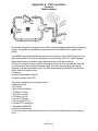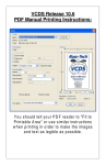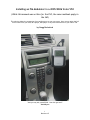
1
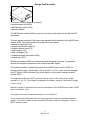
Installing an FM Modulator in a 2005/2006 Volvo V50
(While this manual was written for the V50, the same methods apply to
the S40)
This solution allows the connection of any audio source to your car stereo. Now you can enjoy the full
stereo sound from your iPod, MP3 player, DVD player or any other audio device in your V50 or S40.
by Gregg Rocheford
" And you may ask yourself-Well...How did I get here?"
-David Byrne
1
Revision 6.5
Table of Contents
THE NEED FOR A HOME GROWN SOLUTION .................................................................................... 1
NOTHING IS EASY....................................................................................................................................... 1
FIGURE 1............................................................................................................................................................ 2
FIGURE 2............................................................................................................................................................ 2
WHAT THE HECK IS VADIS?.................................................................................................................... 2
FIGURE 3............................................................................................................................................................ 3
MATERIAL LIST FOR INSTALLATION.................................................................................................. 4
FIGURE 4............................................................................................................................................................ 4
FIGURE 5............................................................................................................................................................ 4
FIGURE 6............................................................................................................................................................ 5
FIGURE 7............................................................................................................................................................ 5
PART CONSTRUCTION PROCEDURE.................................................................................................... 6
FIGURE 8............................................................................................................................................................ 6
PUTTING IT ALL TOGETHER .................................................................................................................. 7
FIGURE 11.......................................................................................................................................................... 7
FIGURE 12.......................................................................................................................................................... 8
FIGURE 13.......................................................................................................................................................... 8
FIGURE 14.......................................................................................................................................................... 9
FIGURE 15........................................................................................................................................................ 10
FIGURE 16........................................................................................................................................................ 11
FIGURE 17........................................................................................................................................................ 11
APPENDIX A - PART LOCATIONS ........................................................................................................... 1
APPENDIX B - SIDE PANEL REMOVAL V50 ......................................................................................... 1
APPENDIX C - S40 COMPONENT LOCATIONS .................................................................................... 1
APPENDIX D - ADDITIONAL INFORMATION ...................................................................................... 1
1
Revision 6.5
The Need for a Home Grown Solution
While the 2005 and 2006 Volvo S40 Sedan and V50 Wagon offer much in the way of aesthetic appeal,
driving excitement and creature comforts, one major drawback is ubiquitous among owners – the Volvo
designers forgot about MP3 integration. This complication has been eliminated in the 2007 V50/S40 line.
MP3 and other types of digital music compression have given music lovers the ability to carry their entire
music collections in containers that are not much larger than a deck of playing cards. As these players
get smaller and less expensive, manufacturers such as Apple Computer are teaming with major
automobile companies to provide integration of players like the iPod into automobile sound systems.
Indeed, many after market in-dash car stereo makers have also seen the light. Long before the popularity
of digital music compression, in-dash stereos have included simple Auxiliary (AUX) input jacks to allow
users to plug-in other audio sources and listen through their automobile speakers. In the last few years,
major after market in-dash stereo manufacturers have offered head units that play MP3 encoded Compact
Discs (CDs). Even in the dark ages, before MP3 compatibility and AUX inputs, one could use a crude but
effective cassette adapter to listen to music in one’s car. However, none of these options are available
to the proud owners of the 2005 and 2006 Volvo S40 and V50.
Nothing is Easy
Without the AUX input, or the MP3 capability of the CD player and the fact that the nifty head unit in the
S40 and V50 does not include the option of a cassette deck, there are not many remaining options. The
option I considered was the FM Modulator route.
Basically, an FM Modulator takes the output from an audio source and turns the output into an FM signal
that, if sent through an FM Tuner, can be used to hear the audio output. There are two means for getting
that FM signal from the Modulator to the tuner:
•
•
FM Transmitter, or
In-Line FM Modulator.
An FM Transmitter takes the signal from the audio source and acts like a little FM Radio station. It
transmits the signal to the Tuner via radio waves. While this works, it neither provides a clean signal, nor
is it reliable in urban areas where other radio signals can easily overpower the meager signal from the
Transmitter. I personally chose to steer clear of this option.
An In-Line FM Modulator also takes the signal from the audio source and turns that signal into an FM
signal. However, the resulting output from the In-Line FM Modulator is not broadcast over radio waves to
transmit the signal to the Tuner. Instead, the FM signal is passed directly into the antenna cable which
then feeds into the Tuner. Some interference can still result from strong urban radio stations, but FM
Modulators are usually equipped with the option for tuning into more than one station in order to allow
the user to select another frequency. For instance, if your FM Modulator is tuned the 89.1 kHz, you would
also tune your in-dash tuner to that frequency to hear the music. If you experience interference from the
Acid Rock station broadcasting on 89.1 or 89.3 kHz, you have the choice to tune your FM Modulator to
another frequency. The range of available station presets varies by manufacturer.
In many automobiles, installing an FM Modulator is rather easy. Simply find the antenna cable in the back
of the Head Unit and plug the antenna cables together from the Head Unit to the Modulator and from the
Modulator back to the antenna. Then, find a power lead and an appropriate ground and connect those
wires, tuck the FM Modulator away neatly behind the dash, plug in the audio source and CRANK IT UP.
Introducing Volvo’s Fibre Optic MOST network. I’m not really up to speed on this, but MOST (Media
Oriented Systems Transport), is a, “…standard that provides a physical layer, an application framework,
and a behavioral model to implement cost-effective entertainment and information systems in vehicles.”
1
Revision 6.5
Here is a good rundown (http://www.edn.com/article/CA250819.html). Unfortunately, if you are not
privy to the source code from the MOST Consortium, you’re up a creek if you wish to hack into the MOST
application network.
In order to get the FM Modulation to work, I had to find a place where the signal from the antenna was
still analog. The S40 and V50 have the signal transformed into a digital signal in the FM amplifier. An FM
modulator cannot transmit a digital signal on fiber optic cable. The analog signal location that I found is
between the window antenna and the FM Amplifier. The FM amplifier, on the V50, is located about 1.5
inches (4 cm) from the rear, side window antenna. (See Figure 1 and Appendix A) Volvo engineers have
moved the locations of these parts within the same model year. So, while this is where I was able to find
the FM amplifier in my car, the location in yours may be vary. The location of the FM amplifier in the S40
is along either the left or right rear pillar. See Figure 2 and Appendix C.
Figure 1
Figure 2
Appendix A shows the locations of the parts in the V50 and S40. Appendix D shows detailed information
regarding removal of body panels for the S40.
What the heck is VADIS?
Before I began to pull parts off of my car to look for the guts of the sound system, I started hanging out at
some Volvo Forums. The best one I found was swedespeed.com (http://forums.swedespeed.com/). I
found that I was not alone in my quest for the illusive answer to the MP3 solution. Still, no one could
provide information, not even the Volvo dealership or, for that matter, the folks at the very factory
where my V50 was put together.
2
Revision 6.5
One thread on the forum mentioned a strange thing called a VADIS. After some web research, I found
what VADIS is not.
It is not,
“Quo Vadis - The epic tale of the birth of Christianity. Vinicius, Emperor Nero's centurion, falls in love
with a Christian and causes a catastrophe.”
or
“…the fastest, easiest, most compact moving-map program for your organizer!”
Instead, VADIS is an acronym for Volvo Aftersales Diagnostic and Information System. It is available for a
bunch of money. Or, you can go to your local Volvo Dealer and beg them to print a copy of a specific
section providing procedures for removing, replacing or altering your new Volvo. By now, I have a
growing library of these sections. Sometimes, however, they are not correct because 2004.5 and 2005
vehicles are different and others may be as well.
The most helpful section I found for this project is the section that shows how to disassemble the rear
compartment. (See Appendix B) Once I had taken these parts out, I found that the parts for which I was
searching were not even installed in my car. But, I was able to find lots of cool wires and an entry point
for the solution of the MP3 problem, the AM/FM Signal Amplifier. (See Figure 3)
Figure 3
Here is the AM/FM Amplifier with the plug barely visible in the upper right corner.
Refer to Figure 1 for the location within the car.
3
Revision 6.5
Material List for Installation
The following section includes a listing of the parts used to create the solution that I used.
1. Two (2) 9 volt plugs
Figure 4
2. One Motorola Male/Female extension cable (I used four (4) feet or 122 cm).
Figure 5
4
Revision 6.5
3. RCA to Mini Adapter
Figure 6
4. FM Modulator - I understand that a modulator with PLL (Phase Locked Loop) is best. After much
trial and error, I have found that the Kenwood KCA-20FM has the most available stations from
which to choose and yielded the best sound. Can you say awesome?
Figure 7
5
Revision 6.5
Part Construction Procedure
The following section shows the process for building the cables.
1. Cut the Motorola cable into two equal lengths
Refer to Figure 8 for steps 2 – 4.
Figure 8
2. Remove the black insulation about one inch back from the cut. Be careful not the harm the fine
wire mesh that lies just under the black insulation.
3. Twist the wire mesh together and move it to one side
4. Remove the white insulation from the center copper core wire, down about .5 inch
Refer to Figure 9 for steps 5 & 6
Figure 9
5. Separate the two 9v connectors into one pair of males and one pair of females
6. Solder the females to the male Motorola piece and the males to the female Motorola piece
6
Revision 6.5
Figure 10
These are your new converter cables!
Putting it all Together
The following section shows the installation of the cables.
Note: Take care not to bend the headliner because once it bends, you cannot get the creases out.
1. Unplug the antenna leads. The window antenna is attached to the AM/FM Amplifier by a one inch
long wire. The plug that connects the antenna to the amplifier is shown in Figure 11. That plug
has prongs that are very much like 9 volt battery terminals.
Figure 11
7
Revision 6.5
2. Attach the converter cables that you made (See Figure 10). Feed the cables over the headliner.
Figure 12
Route the cables along the window toward the rear corner. There are also parts related to the
side curtain airbag along this route. Don’t wrap the cables around any of that hardware.
In the rear corner of the car is a plastic corner cover that has a small access plate. This access
plate can be removed without much effort. Using your fingers, pull up and out on the inboard
side of the access plate. Once that corner has been released, you can rotate the access panel out
of the tail light access space. Figure 13 can be found in your V50 Owner’s Manual on Page 161 or
on line at: http://apps.volvocars.us/ownersdocs/2005/2005_V50/05v50_00.htm#contents
Removing the tail light bulb holder
Figure 13
The cables will reach into the tail light access space. You will need to feed the coaxial cables
from the FM Modulator into the tail light access space from the placement location.
3. Remove the side panels as shown in Appendix B.
Figure 14 shows the location that I used for placement of the FM Modulator. According to the
VADIS, the AFM (AM/FM Tuner) should have been here. However, I found out that the 2005 V50
no longer has the AFM in this location.
8
Revision 6.5
Figure 14
4. Connect the power wires from the FM Modulator to a power source. I could not find a “switched”
Power source – a power source that was controlled by the key in the ignition. I used the Power
Point (cigarette lighter) in the back of the car. If you don’t have that option, there should still be
other places from which you can get power. A square, white plug is shown in Figure 14. Simply
soldering the ends of the wires and wedging them into the back of the plug and then securing the
wires with electrician’s tape works well. You can also mount pancake connectors to the wire and
wedge that into the back end of the plug so that the pancake connectors make contact with the
brass of the power plug wires.
Either way, be careful not to touch the wires to a ground or each other or you will blow a fuse.
The fuse for the Power Point is easy to get to, but unless you have extra fuses, you will need to
make a trip to buy more. See Figure 15 or Page 165 in your V50 Owner’s Manual or on line at:
http://apps.volvocars.us/ownersdocs/2005/2005_V50/05v50_00.htm#contents
Once the wire is taped and secure in the plug, you can reconnect the plug on the Power Point.
9
Revision 6.5
Fuse Replacement
Fuse box in the passenger compartment
The fuse box in the passenger compartment is located under the glove compartment.
To access the fuses:
1. Remove the upholstery covering the fuse box by first pressing in the center pins in the mounting clips approximately 0.5 in (1 cm)
with a small screwdriver and then pulling the pins out.
2. Turn both retaining screws (2) counterclockwise until they release.
3. Fold down the fuse box (3) half way. Pull it toward the seat until it stops. Fold it down completely. The fuse box can be unhooked
completely.
4. Replace the blown fuse.
5. Close the fuse box in reverse order.
6. Pull the center pins fully out of the mounting clips, secure the upholstery with the mounting clips and press the pins into the
mounting clips again. The mounting clips then expand, holding the upholstery in position.
Fuses in the passenger compartment
77. 12-volt socket in cargo area, auxiliary equipment control module (AEM), 15A
Figure 15
5. Connect the Motorola plugs from the FM Modulator to your converter cables in the tail light
access.
6. Determine a common test frequency to which your radio and Modulator will be set (Consult your
modulator’s documentation).
7. Connect your MP3 player or other external audio source to the Audio IN of the FM Modulator using
an adapter similar the one shown in Figure 6.
10
Revision 6.5
8. Test it...
Figure 16
9. Install it...
Figure 17
10. Enjoy with excessive delight!
11
Revision 6.5
Appendix A - Part Locations
Function
Radio reception
16/16
During radio reception the signals from the AM or FM wavebands are gathered by the antenna
system. The signals are decoded and are transmitted to the AM/FM tuner module (AFM)
(16/94).
The AM/FM tuner module (AFM) then transmits the signals on via the MOST network to the
audio module (ADD) (16/105) and infotainment control module (ICM) (16/1).RDS-reception
(Radio Data System) is possible (market dependant) during FM transmissions.
The User can choose to store channels manually one at a time or to automatically store the
10 channels with the strongest broadcast signal. Automatic search stores the program
channels in ascending frequency order. For each preset channel the AM/FM tuner module
(AFM) stores information about:
• frequency
• program identification code (PI)
• program channel name (PS).
The control module stores information about:
• Regional: On/Off
• AF: On/Off
• EON: Off/Local/Distant
• TP Station: On/Off
• TP Search: On/Off
• TP Search: On/Off
• Favorite TP Station
• Favorite News (PTY1)
• Activated PTY categories
• Waveband: AM/FM/Off
• Latest stored frequency.
The control module uses the information to reset the user settings between each driving
cycle.
1
Revision 6.5
Design Control module
The system for radio reception consists of
• antenna system for AM/FM
• AM/FM tuner module (AFM)
• antenna amplifier.
The AM/FM tuner module (AFM) has the task of receiving radio signals for the AM and FM
wavebands.
The radio signals received by the antenna are decoded and transmitted to the AM/FM tuner
module (AFM). The signals contain information about (see below):
• alternative frequencies (AF)
• program identification code (PI)
• program channel name (PS)
• traffic program (TP)
• traffic messages (TA)
• extended program information (EON)
• program type (PTY).
AM/FM tuner module (AFM) has a 5-band equalizer integrated in the unit. The equalizer
controls the frequency reproduction from the received radio signals.
The antenna amplifier is supplied with power by the AM/FM tuner module (AFM), via
phantom power supply (coaxial cable), with a nominal 11 ± 0.5 V. If the vehicle is equipped
with RTI (Road Traffic Information) the power supply is via the traffic message channel
module (TMC).
The diagnostic trouble code (DTC) is stored and the system is shut down if the voltage
exceeds 13.5 ± 0.5 V. The voltage is regulated to the battery capacity if the battery voltage
is below 10.5V.
When the ignition is switched off the power consumption of the AM/FM tuner module (AFM)
must not exceed 0.1 mA.
The system can endure temperatures between -40 <C and 85 <C.
The control module checks the input and output signals through an integrated diagnostic
system. The control module communicates with directly connected components, and via
MOST communication.
2
Revision 6.5
Alternative frequencies (AF)
Information from RDS-stations about:
• which frequencies the present program can be found
• program identification code (PI)
• program channel name (PS).
The control module stores the information in a list. If the signal begins to fade the AM/FM
receiver searches the list for a transmitter with a stronger signal. The function can be
activated and deactivated by the User.
Program identification code (PI)
The code which the control module attributes to a specific program selection button.
Contains the country code and the character of the network on which the program is
broadcast.
Program channel name (PS)
An 8 character channel name stored in the control module.
Traffic program (TP)
Information from the RDS-station about that the station is transmitting traffic messages.
Traffic messages (TA)
The program channel transmits a traffic message code to the RDS receiver that a traffic
message is to be transmitted. The RDS receiver which are set to a different channel change
to the channel on which the traffic message is transmitted. The traffic message is used to
inform the User of relevant road conditions such as road works, accidents etc. After the
message has been received the control module returns to the source that was activated
before the interruption. The function can be activated and deactivated by the User.
Extended program information (EON)
Signals sent by RDS-stations containing information about program services such as:
• alternative frequencies (AF)
• traffic messages (TA)
• program channel name (PS)
• program type (PTY) on frequencies within the same radio network.
Program type (PTY)
Description of what sort of program types the channel is currently broadcasting. For
example news, music etc. There are 31 different definitions of program type (PTY1 PTY31).The user can activate/deactivate all program types except PTY31 (alarm) which is
preset and cannot be deactivated.
3
Revision 6.5
Antenna system
The antenna system for the AM/FM tuner module (AFM) consists partly of an AM antenna
and partly of a dual antenna system (Diversity reception) for FM (FM main and FM sub). The
dual antenna system is used to reduce Multipath interference.
On 4-door vehicles a combined AM/FM (main and sub) and TMC-antenna is used. The
antenna is integrated in the rear windshield.
On 5-door vehicles there are two antennae. A combined AM/FM main antenna, which is
integrated in the right-hand side rear window. An FM sub antenna, which is a combined FM
sub/TMC antenna and is integrated in the rear windshield.
The signals from the antennae are amplified or adjusted by an antenna amplifier. The
signals from the FM sub/TMC antenna are transmitted via the antenna amplifier to the traffic
message channel module (TMC). The traffic message channel module (TMC) in turn
transmits the FM sub signals to the AM/FM tuner module (AFM).
System overview
Control module
The AM/FM tuner module (AFM) has the task of receiving radio signals on the AM or FM
wavebands then processing and transmitting the signals onwards on the MOST network.
There are four different market configurations:
• Europe
• USA
• Australia
• Japan.
4
Revision 6.5
In 4-door vehicles the control module is located on the parcel shelf. In 5-door vehicles the
control module is located under the right-hand rear side window.
The control module uses optical serial communication to communicate with other
components on the MOST network. This means that all communication with the control
module is via the infotainment control module (ICM).
Any diagnostic trouble codes (DTCs) are stored in the control module memory. This
information can be read off using VIDA via the data link connector (DLC) in the vehicle.
For further information, also see Signal specifications.
Signals
The table below summarizes the input signals to and output signals from the AM/FM tuner
module (AFM). The signal types are divided into directly connected signals and MOST
communication. The illustration below displays the same information with the Volvo
component designations.
Input signals
Output signals
Directly connected:
- Antenna amplifier (16/16) - Traffic message
channel module (TMC) (16/49) (option).
Directly connected:
- Antenna amplifier (16/16) - Traffic message
channel module (TMC) (16/49) (option).
Via MOST communication:
- Infotainment control module (ICM) (16/1) Audio module (AUD) (16/105).
Via MOST communication:
- Infotainment control module (ICM) (16/1)
- Audio module (AUD) (16/105).
AFM
5
Revision 6.5
Appendix B - Side Panel Removal V50
Side panel cargo compartment, replacing
Note! The illustrations in this service information are used for different model years and/or models. Some
variation may occur. However, the essential information in the illustrations is always correct.
Removal
Removing the side panel in the cargo compartment
Remove:
• the outer load floor.
•
the 2 covers.
Hint: Use an electrician's screwdriver to remove the cover.
Remove:
• the screws, 1 per loading eye, and remove the loading
eyes.
•
the 1 screw. Remove the panel over the seat belt reel.
1
Revision 6.5
•
1 screw.
Remove the sealing trim strip.
Remove:
• the side cushion. See: Upholstery, side cushion, replacing
• the lower panel on the C post. It is secured with 4 clips.
Detach the molding in the door opening by the C-post panel.
Start at the rear edge of the side panel. Pull the panel straight out
so that the 2 clips release. Repeat the procedure at the front
edge so that the 1 clip releases.
Installation
Note! For tightening torques, see: Tightening torque .
Installing the side panel in the cargo compartment
Press the side panel into place. Start at the front edge.
Hint: Detach the sill trim panel. Pull the sill trim panel straight up
so that it is easier to install the side panel in the rear edge.
2
Revision 6.5
Press the lower part of the panel on the C-post into place.
Install:
• the molding in the door opening
• 1 M5 screw. Tighten.
• the panel over the seat belt reel. Use the 1 M5 screw. Tighten
• the loading eyes using the 2 M8 screws. Tighten
• the 2 covers for the loading eyes
• the outer load floor
• the side cushion. See: Upholstery,side cushion, replacing
3
Revision 6.5
Appendix C - S40 Component Locations
Vehicle Model: S40 (04-)
Year: 2005
Steering: L.H.D
BodyStyle: 4DRS S.R
AM/FM tuner module (AFM), replacing
Note
The illustrations in this service information are used for different model years and/or models. Some variation may occur.
However, the essential information in the illustrations is always correct.
Preparatory work
Ignition off
Ignition off.
Remove the parcel shelf. See: Parcel shelf, replacing.
Removing the AM/FM tuner module (AFM)
Hint:
In vehicles with a road traffic information module (RTI), the traffic message channel module (TMC) is located behind the AM/FM
tuner module (AFM).
Remove:
•
the 3 connectors
•
1 M6 nut
•
the 1 M6 screw
•
the control module.
Installation
Note
For tightening torques, see: General tightening torque.
1
Revision 6.5
Installing the AM/FM tuner module (AFM)
Install:
•
the control module
•
the 1 M6 screw
•
1 M6 nut
•
the 3 connectors
•
the parcel shelf. See: Parcel shelf, replacing.
Finishing
Note
After replacing the AM/FM tuner module (AFM), new software must be ordered and the module programmed.
Ordering software
Order software. See: Order
Programming the AM/FM tuner module (AFM)
Program the new control module. See: Load
Function test
Test the function.
Audio Module (AUD), replace
Note
The illustrations in this service information are used for different model years and/or models. Some variation may occur.
However, the essential information in the illustrations is always correct.
Preparatory work
Ignition off
Ignition off.
2
Revision 6.5
Removal
Removing the audio module (AUD)
Push the cargo compartment side panel to one side. See: Side panel cargo compartment, replacing.
Remove:
•
the 3 M6 nuts
•
the control module.
Disconnect the connectors.
Note
Any global positioning system module (GPS) (1) installed in the vehicle must be transferred to the new audio module (AUD).
Installation
Note
For tightening torques, see: General tightening torque.
Installing the audio module (AUD)
Note
Check that there is no dirt in the optical connectors.
The bend radius of the optic cables must not be less than 25 mm.
Install:
•
the connectors
•
the control module
•
3 M6 nuts.
Install the cargo compartment side panel. See: Side panel cargo compartment, replacing.
Finishing
Note
After replacing the audio module (ADD), new software must be ordered and the module programmed.
Ordering software
Order software. See: Order
Programming the audio module (AUD)
Program the new control module. See: Load
3
Revision 6.5
Amplifier windshield antenna, replacing
Note
The illustrations in this service information are used for different model years and/or models. Some variation may occur.
However, the essential information in the illustrations is always correct.
Removal
Removing the amplifier
Remove:
•
the C-post panel. See: Panel C-post, replacing
•
the 3 connectors
•
1 M6 screw.
Remove the amplifier. Use an electrician's screwdriver at the top edge to release the clip.
Installation
Note
For tightening torques, see: General tightening torque.
Installing the amplifier
Install:
•
the amplifier
•
the 1 M6 screw
•
the 3 connectors
•
the C-post panel. See: Panel C-post, replacing.
Panel C-post, replacing
Note
The illustrations in this service information are used for different model years and/or models. Some variation may occur.
However, the essential information in the illustrations is always correct.
4
Revision 6.5
Removal
Removing the C-post panel
The panel consists of 3 parts. Remove the upper part first. Then remove the lower part. Finally remove the center part.
Fold down the backrest cushion.
Remove the weatherstrip around the door.
Remove:
•
the side cushion. See: Upholstery, side cushion, replacing
•
the upper panel. Pull the panel straight inwards into the vehicle
•
the holder clip, x 1.
Pull the lower panel straight inwards into the vehicle. Pry it out of the sill trim panel.
Pull the center panel straight inwards into the vehicle. Fold it out.
5
Revision 6.5
Installation
Installing the C-post panel
Install:
•
the center panel. Fold the panel in and press it into place
•
the lower panel. Guide the panel into the guide channel against the sill trim panel. Press the panel into place
•
the upper panel. Guide the rear edge of the panel and secure the holder clip. Press the panel into place
•
the side cushion. See: Upholstery, side cushion, replacing
•
the weatherstrip around the doors.
Fold the backrest cushion back into position.
6
Revision 6.5
Appendix D - Additional Information
Web URLs to additional Information
Swedespeed.com
http://forums.swedespeed.com/zeroforum?id=54
S40 installation with AM reception preserved (Thank you, Roddy)
http://forums.swedespeed.com/zerothread?id=70953
1
Revision 6.5