1
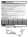
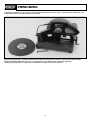
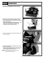
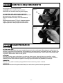
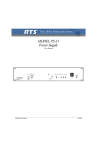
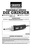
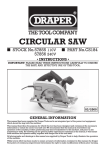
350mm (14") CHOP SAW STOCK No.55809 (110V). 52623 (230V). PART No.CS14A. • INSTRUCTIONS • IMPORTANT: PLEASE READ THESE INSTRUCTIONS CAREFULLY TO ENSURE THE SAFE AND EFFECTIVE USE OF THIS TOOL. 09/98 350mm (14") CHOP SAW ■ STOCK No.55809 (110V). 52623 (230V). ■ PART No.CS14A. CONTENTS: Page Nos. Specification/guarantee ..................................................................................................................... 1 General safety instructions................................................................................................................. 2 Safety rules for chop saw.................................................................................................................... 3 Power supply...................................................................................................................................... 4 Unpacking.......................................................................................................................................... 5 Know your chop saw........................................................................................................................... 6 Assembly ........................................................................................................................................... 7 Operation ........................................................................................................................................... 8 Service requirements and maintenance ............................................................................................. 9 Trouble shooting ............................................................................................................................... 10 DECLARATION OF CONFORMITY We Draper Tools Ltd. Hursley Road, Chandlers Ford, Eastleigh, Hampshire. SO53 1YF. England. Declare under our sole responsibility that the product: Part Number:- CS14A. Stock No. 55809 (110V). 52623 (230V). Description:- CHOP SAW To which this declaration relates is in conformity with the following directive(s) 89/392/EEC, 89/336/EEC & 73/23/EEC With reference to: EN55014-2:1997, EN55104:1993, EN61000-3-2:1995 & EN61000-3-3:1995 J.N.DRAPER Managing Director 09/98 SPECIFICATION Whilst every effort has been made to ensure accuracy of information given in this manual is correct at the time of going to print, the Draper Tools policy of continuous improvement determines the right to change specification without notice. Stock No. .............................................................. 55809 ...................... 52623 Motor...................................................................... 2100W. ...................... 2100W. Voltage .................................................................. 110V ...................... 230V/50Hz. RPM ........................................................................ 3800RPM. ...................... 3300RPM. Blade diameter ...................................................... 350mm (14") .................... 350mm (14"). Bore diameter ........................................................ 1". ...................... 1". Capacity pipe ........................................................ 120mm. ...................... 120mm. Square .................................................................... 100mm. ...................... 100mm. Rectangular ............................................................ 70 x 182mm. ...................... 70x182mm. Angle iron .............................................................. 165 x 84mm. ...................... 165x84mm. Weight.................................................................... 20kg. ...................... 20kg. Sound pressure level .............................................. 108.86dbA. ...................... 108.86dbA. Sound power level .................................................. 121.86dbA. ...................... 121.86dbA. WEAR EAR PROTECTION GUARANTEE Draper stationary power tools have been carefully tested and inspected before shipment and are guaranteed to be free from defective materials and workmanship for a period of 12 months from the date of purchase except where tools are hired out when the guarantee period is reduced to ninety days from the date of purchase. Should the machine develop any fault, please return the complete tool to your nearest authorized warranty repair agent or contact Draper Tools Limited, Chandler's Ford, Eastleigh, Hampshire, SO53 1YF. England. Telephone: (01703) 266355. If upon inspection it is found that the fault occurring is due from defective materials or workmanship, repairs will be carried out free of charge. This guarantee does not apply to normal wear and tear, nor does it cover any damage caused by misuse, careless or unsafe handling, alterations, accident, or repairs attempted or made by any personnel other than the authorized Draper warranty repair agent. This guarantee applies in lieu of any other guarantee expressed or implied and variations of its terms are not authorized. Your Draper guarantee is not effective unless you can produce upon request a dated receipt or invoice to verify your proof of purchase within the 12 month period. Please note that this guarantee is an additional benefit and does not affect your statutory rights. DRAPER TOOLS LIMITED -1- SAFETY WARNING WARNING Please read the following instructions carefully, failure to do so could lead to serious personal injury. IMPORTANT This machine was designed for metal cutting applications only. Draper Tools Limited recommends that this machine should not be modified or used for any application other than that for which it was designed. If you are unsure of its relative applications do not hesitate to contact us in writing and we will advise you. GENERAL SAFETY INSTRUCTIONS FOR MACHINE TOOLS 1. KNOW YOUR MACHINE TOOL Read and understand the owner's manual and labels affixed to the tool. Learn its application and limitations as well as the specific potential hazards peculiar to this tool. 2. EARTH ALL TOOLS This tool is equipped with an approved 3-core cable. The green and yellow conductor in the core is the earth wire. Never connect the green and yellow wire to a live terminal. 3. KEEP GUARDS IN PLACE and in working order. 4. REMOVE ADJUSTING KEYS AND WRENCHES Form a habit of checking to see that keys and adjusting wrenches are removed from tool before turning it on. 5 KEEP WORK AREA CLEAN Cluttered areas and benches invite accidents. Floor must not be slippery due to oil or sawdust. 6. AVOID DANGEROUS ENVIRONMENT Do not use power tools in damp or wet locations or expose them to rain. Keep work area well lit. Provide adequate surrounding work space. 7. KEEP CHILDREN AWAY All visitors should be kept a safe distance from work area. 8. MAKE WORKSHOP CHILDPROOF - with padlocks, master switches, or by removing starter keys. 9. DO NOT FORCE TOOL It will do the job better and safer at the rate for which it was designed. Continued ... resistant lenses, they are NOT safety glasses. Also, use face or dust mask if cutting operation is dusty and ear protectors (plugs or muffs) during extended periods of operation. 13. SECURE WORK Use clamps or a vice to hold work. This free both hands to operate tool. 14. DO NOT OVERREACH Keep proper footing and balance at all times. 15. MAINTAIN TOOLS WITH CARE Keep tools sharp and clean for best and safest performance. Follow instructions for lubricating and changing accessories. 16. DISCONNECT POWER TO THE TOOLS Before servicing, when changing accessories such as cutters etc. 17. AVOID ACCIDENTAL STARTING Make sure switch is in 'OFF' position before plugging in cable to the power supply. 18. USE RECOMMENDED ACCESSORIES Consult the owner's manual for recommended accessories. Follow the instructions that accompany the accessories. The use of improper accessories may cause hazards. 19. NEVER STAND ON TOOL Serious injury could occur if the tool is tipped or if the cutting tool is accidentally contacted. Do not store materials above or near the tool such that it is necessary to stand on the tool to reach them. 20. CHECK DAMAGED PARTS Before further use of the tool, a guard or other part that is damaged should be carefully checked to ensure that it will operate properly and perform its intended function. Check for alignment of moving parts, breakage of parts, mounting and any other conditions that may affect its operation. A guard or other part that is damaged should be properly repaired or replaced. 10. USE RIGHT TOOL Do not force tool or attachment to do a job for which it was not designed. 11. WEAR PROPER CLOTHING Do not wear loose clothing, gloves, neckties or jewellery (rings, wristwatches) to catch in moving parts. NON SLIP footwear is recommended. Wear protective hair covering to contain long hair. Roll long sleeves above the elbow. 21. DIRECTION OF FEED Feed work into a blade or cutter against the direction of rotation of the blade or cutter only. 22. NEVER LEAVE MACHINE RUNNING UNATTENDED Turn power off. Do not leave machine until it comes to a complete stop. 12. USE SAFETY GOGGLES (Head Protection) Wear safety goggles (must comply with BS 2092) at all times. Normal spectacles only have impact -2- SAFETY RULES FOR CHOP SAWS 18. MAKE SURE abrasive wheel is not contacting workpiece before switch is turned on. 1. WARNING: Do not operate your abrasive cut-off saw until it is completely assembled and installed according to the instructions. 19. ALLOW the motor to come up to full speed before starting cut. 2. IF YOU ARE NOT thoroughly familiar with the operation of abrasive cut-off saws, obtain advice from your supervisor, instructor or other qualified person. 20. AFTER TURNING MACHINE ON, lower wheel lightly until it comes into contact with the workpiece and then draw wheel firmly though the cut. DO NOT allow the wheel to chatter and jump as this may cause the wheel to wear out of round resulting in poor cutting and possible broken wheels. 3. WEAR safety goggles, face shield, respirator, body apron, headcovering, safety shoes, long tight-fitting sleeves and gloves. 4. USE ONLY recommended reinforced abrasive wheels with blotters. 21. ANY material can be cut more satisfactorily when placed in position for the wheel to cut with the least arc of contact. 5. TIGHTEN arbor screw and all clamps before operating. 6. MAKE SURE spindle lock is disengaged before operating. 22. THE NUMBER of cuts per wheel, as well as the quality of cut, may vary considerably with the cutting time. Fast cuts cause the wheel to wear more rapidly but also help to reduce discoloration and burr. This is especially noticeable when cutting light gauge tubing. When coming through the bottom wall, with the longer arc of contact, do not slow-up but give a vigorous pull. This keeps the metal from overheating and dragging off in a heavy burr. 7. ALWAYS keep guards in place and working properly. 8. KEEP hands clear of cut-off wheel. 9. SECURE workpiece properly. Work should be straight and firmly clamped to avoid possible movement and pinching as the cut nears completion. 23. USE the wheel guard at all times. 10. NEVER cut anything freehand. 11. NEVER reach behind or beneath the cut-off wheel. 24. NEVER operate the machine in an area with flammable liquids or gases. 12. MAKE SURE the wheel has come to a complete stop before removing or securing workpiece or changing workpiece angle. 25. TO AVOID electric shock, do not use under damp conditions or expose to rain. 26. THIS tool is designed for ferrous metals only. DO NOT attempt to cut wood, masonry, aluminium or magnesium with this tool. 13. MAKE SURE the inside surfaces of the wheel flanges as well as the sides of the wheel are free from any foreign matter. 27. AFTER installing a new wheel, never start the tool with a person in line with the wheel. ALWAYS run the tool for approximately one minute before cutting. If the wheel has an undetected crack or flaw, it could burst in less than one minute. 14. WHEN MOUNTING the wheel, care should be taken to tighten the arbor screw only enough to hold the wheel firmly and to prevent wheel slippage. Excessive tightening may result in damaging the wheel and springing the wheel flanges. 15. USE ONLY abrasive wheels rated at 3900 RPM or higher. 28. DISCONNECT from power supply before servicing or adjusting tool. 16. ALWAYS check the wheel for cracks or other damage before operation. Replace cracked or damaged wheel immediately. 29. SHOULD any part of your machine be missing, damaged or fail in any way, or any electrical component fail to perform properly, shut-off switch and remove plug from power supply outlet. Replace missing, damaged or failed parts before resuming operation. 17. USE ONLY wheel flanges specified for your machine. -3- POWER SUPPLY CONNECTING YOUR MACHINE TO THE POWER SUPPLY: (230V ONLY) To eliminate the possibility of an electric shock your machine has been fitted with a BS approved, non rewireable moulded plug and cable which incorporates a fuse, the value of which is indicated on the pin face of the plug. Should the fuse need to be replaced an approved BS1362 fuse must be used of the same rating, marked thus . The fuse cover is detachable, never use the plug with the cover omitted. If a replacement fuse cover is required, ensure it is of the same colour as that visible on the pin face of the plug (i.e. red). Fuse covers are available from your Draper Tools stockist. If the fitted plug is not suitable, it should be cut off and destroyed. *The end of the cable should now be suitably prepared and the correct type of plug fitted. See below. *WARNING: A plug with bare flexible wires exposed is hazardous if engaged in a live power socket outlet. WARNING THIS APPLIANCE MUST BE EARTHED. Green and Yellow - Earth, Blue - Neutral, Brown - Live. As these colours may not correspond with the coloured markings identifying the terminals in your plug, proceed as follows.: The wire which is coloured green and yellow must be connected to the terminal in the plug which is marked with the letter ‘E’ or by the earth symbol or coloured green or green and yellow. The wire which is coloured blue must be connected to the terminal which is marked with the letter 'N' or coloured black or blue. The wire which is coloured brown must be connected to the terminal which is marked with the letter 'L' or coloured red or brown. (N.B. Three phase machines must be connected by a qualified electrician). WARNING: (110V ONLY) Single phase 110 volt machines must be connected using the relevant coding and matching the colour of the flexible cable to that of the plug. The procedure is as follows: 1. Connect green and yellow coloured core to the plug terminal marked letter 'E' earth symbol or coloured green or green and yellow. 2. Connect brown coloured core to plug terminal marked letter 'L' (live). 3. Connect blue colour core to plug terminal marked letter 'N' (neutral). EXTENSION LEAD CHART: Extension lead sizes shown assure a voltage drop of not more than 5% at rated load of tool. Ampere rating (on Name plate) Extension cable length 7.5m 15m 22.5m 30m 45m 3 6 10 13 1.0 1.0 1.0 1.25 1.5 1.25 1.5 1.5 1.5 2.5 Wire Size mm2 0.75 0.75 0.75 0.75 0.75 0.75 0.75 0.75 0.75 1.25 WIRING DIAGRAM BLUE BLACK BRUSH SWITCH N.C. BROWN ARMATURE N.O. -4- BLACK UNPACKING Carefully unpack the chop saw and all the loose items from the carton Fig.1. illustrates the chop saw and all the loose items that are packed in the carton. Fig.1 Now referring to Fig.1. carefully check that all the parts are present. Please contact the Draper Power Helpline (01703) 494344 if you have any enquiries i.e. problems with assembly, apparent missing/damaged parts, help with accessories available or technical advice. -5- KNOW YOUR CHOP SAW Fig.2 ✕✌ ✕✙✌ ✖✌ ✜✌ ✗✌ ✘✌ ✙✌ ✢✌ ✕✔✌ ✚✌ ✕✗✌ ✕✚✌ ✕✖✌ ✕✛✌ ✛✌ ✕✕✌ ✕✘✌ ✕✌ Trigger locking button ✕✔✌ Depth stop ✖✌ Trigger switch ✕✕✌ Lock nut ✗✌ Transportation handle ✕✖✌ Backstop ✘✌ Spindle lock ✕✗✌ Quick release lever ✙✌ Power cord ✕✘✌ Base ✚✌ Head locking pin ✕✙✌ Brush cap ✛✌ Hex wrench ✕✚✌ Clamping handle ✜✌ Wheel guard ✕✛✌ Vice clamp ✢✌ Abrasive wheel -6- ASSEMBLY 1. This cut-off saw is shipped with the cutting head locked in the down position as shown in Fig.3. Fig.3. ✪✌ 2. Pull locking pin ✪✌ Fig.3. to enable the cutting head to be in the up position as shown in Fig.3. 3. Lock the spindle shaft by depressing shaft locking button ✭✌ see Fig. 6. Using the hex key provided (inserted in the base), loosen the wheel flange securing bolt ✫✌. Remove the outer flange ✬✌ and install the cutting disc on the arbor shaft. Fig.4. Fig.4. ✬✌ ✫✌ 4. Fit the outer flange ✬✌ then tighten by hand the hex bolt ✫✌ Fig.5. ✬✌ ✫✌ Fig 5. 5. Lock the spindle shaft by depressing shaft locking button ✭✌ see Fig.6. Make sure the spindle shaft is secured by turning the cutting wheel by hand. Then, using the hex wrench, tighten hex bolt ✫✌. Fig.5. NOTE: Do not overtighten as this may cause damage to the cutting disc. ✭✌ -7- Fig.6. OPERATION 1. On-off switch To start the chop saw, depress the trigger locking button ✮✌ and press the trigger switch ✯✌. The saw can now be operated until the trigger is released Fig.7. NOTE: We suggest that when the machine is not in use, the switch ✯✌ be locked in the off position using a padlock ✰✌ (not supplied) through the holes in the trigger switch as shown in Fig.7. Fig.7. ✮✌ ✰✌ ✯✌ Fig.8. 2. Adjusting depth of cutting wheel Screw the adjusting screw ✱✌ clockwise, then secure the bolt by tightening the nut ✳✌ for deeper cutting. For shallow cutting screw the adjusting screw anti-clockwise. See Fig.8. ✱✌ ✳✌ Fig 9. 3. Using clamp device to secure workpiece For quick adjustment, disengage quick release lever ✴✌. The vice clamp ✶✌ can now be pushed in or withdrawn to accommodate the workpiece. Engage quick release lever ✴✌ then tighten clamp using the clamping handle ✵✌. See Fig.9. ✶✌ ✴✌ ✵✌ Fig.10. 4. Angle cutting Loosen screw ✷✌ with the hex key provided. Then adjust fence ✹✌ to the required angle. Tighten screw. Backstop can be adjusted backwards and forwards to meet your requirements. Fig.10. ✷✌ -8- ✹✌ SERVICE REQUIREMENTS Brush inspection and replacement. Fig.11. CAUTION: Before inspecting the brushes, disconnect the machine from the power supply ✱✌ BRUSH WEAR AND REPLACING BRUSHES On new machines check for brush wear after the first 50 hours of use, then every 10 hours. Replace brushes when they have worn down to 5mm. Unscrew brush covers ✱✌ Fig.11. Remove brushes Fig.12. Check for wear or replace. NOTE: When replacing brushes always replace both brushes. Fig.12. MAINTENANCE AFTER EACH USE: Disconnect the plug from the power supply. Remove the disc and flanges. Wipe deposits of dust from the housing and guard. Check operation and condition of the lower guard, it should be securely attached and working properly. The cable and tool should be wiped occasionally with a clean cloth and mild soap only to prevent deterioration from oil and grease. CAUTION: Certain cleaning agents and solvents can damage plastic parts. Some of these are: gasoline, carbon tetrachloride, chlorinated cleaning solvents, ammonia and household detergents that contain ammonia. Avoiding use of these and other types of cleaning agents minimizes the possibility of damage. WARNING: The use of any other accessory not specified in this manual may create a hazard. WARNING: Electrical or mechanical repairs should only be carried out by trained service personnel. -9- TROUBLESHOOTING WARNING: FOR YOUR OWN SAFETY ALWAYS TURN THE MAIN SWITCH ON THE MACHINE “OFF” AND REMOVE THE PLUG FROM THE POWER SUPPLY BEFORE CARRYING OUT ANY MAINTENANCE OR TROUBLESHOOTING. MOTOR Trouble Probable Cause Remedy Motor does not start. 1. Fuse. 1. 13 amp time delay fuse or circuit breaker. 2. See “Maintenance”. Authorized service agent. 2. Brushes worn. 3. Other. Brush sparking when released. 1. Normal - automatic brake working properly. GENERAL Trouble Probable Cause Remedy Angle of cut not accurate. 1. Misalignment. 1. Check for worn pivot. Powerhead wobbles. 1. Loose pivot points. 1. Check/replace worn parts. Power head will not rise fully. 1. Part failure. 2. Pivot spring not replaced properly after service. 1. Authorized service agent. 2. Authorized service agent. Disc binds, jams 1. Improper operation. 2. Warped disc. 1. See basic saw operation. 2. Replace disc. Tool vibrates or shakes. 1. 2. 3. 4. 1. 2. 3. 4. Disc not round. Disc damaged. Disc loose. Other. - 10 - Replace disc. Replace disc. Tighten wheel flange securing bolt. Authorized service agent. NOTES NOTES NOTES DRAPER TOOLS LTD. Hursley Road, Chandler's Ford, Eastleigh, Hants. SO53 1YF. England. Tel: (01703) 266355. Fax: (01703) 260784. YOUR DRAPER STOCKIST Published by Draper Tools Ltd. No part of this publication may be reproduced, stored in a retrieval system or transmitted in any form or by any means, electronic, mechanical, photocopying, recording or otherwise without prior permission in writing from Draper Tools Ltd.