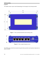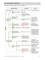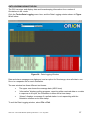
1
ORION RADIO MODEM WITH I/O
OPERATING INSTRUCTIONS
1892 1335
Figure 1 - Orion Radio Modem
Figure 2 - Orion Radio Modem - OEM PCB version
1892 1335 - Orion Radio Modem Operating Instructions - v2.9 / Aug 2009
1
2
1892 1335 - Orion Radio Modem Operating Instructions - v2.9 / Aug 2009
Contents
Contents . . . . . . . . . . . . . . . . . . . . . . . . . . . . . . . . . . . . . . . . . . . . . . . . . . . . . . . .
INTRODUCTION TO THE ORION AND ITS USES . . . . . . . . . . . . . . . . . . . . . . . .
FEATURE OVERVIEW . . . . . . . . . . . . . . . . . . . . . . . . . . . . . . . . . . . . . . . . . . . . .
Part One - the Orion Unit . . . . . . . . . . . . . . . . . . . . . . . . . . . . . . . . . . . . . . . . . . . . . . . .
ORION MODES . . . . . . . . . . . . . . . . . . . . . . . . . . . . . . . . . . . . . . . . . . . . . . . . . . .
3
5
5
7
9
Mode U - Data Only . . . . . . . . . . . . . . . . . . . . . . . . . . . . . . . . . . . . . . . . . . . . . . . . . . . . . . . . . . .
Mode R - Repeater . . . . . . . . . . . . . . . . . . . . . . . . . . . . . . . . . . . . . . . . . . . . . . . . . . . . . . . . . . .
Mode I - Independent Telemetry . . . . . . . . . . . . . . . . . . . . . . . . . . . . . . . . . . . . . . . . . . . . . . . . .
Mode E - Externally-controlled Telemetry . . . . . . . . . . . . . . . . . . . . . . . . . . . . . . . . . . . . . . . . . .
Mode L - Data Logging . . . . . . . . . . . . . . . . . . . . . . . . . . . . . . . . . . . . . . . . . . . . . . . . . . . . . . . .
10
10
10
12
13
ADDRESSING . . . . . . . . . . . . . . . . . . . . . . . . . . . . . . . . . . . . . . . . . . . . . . . . . . . 14
ALARMS AND ALERTS . . . . . . . . . . . . . . . . . . . . . . . . . . . . . . . . . . . . . . . . . . . . 16
Failsafe Feature . . . . . . . . . . . . . . . . . . . . . . . . . . . . . . . . . . . . . . . . . . . . . . . . . . . . . . . . . . . . . . 17
SERIAL INTERFACE CONFIGURATION . . . . . . . . . . . . . . . . . . . . . . . . . . . . . . 19
AT commands . . . . . . . . . . . . . . . . . . . . . . . . . . . . . . . . . . . . . . . . . . . . . . . . . . . . . . . . . . . . . . . 19
Graphical User Interface (GUI) and SCADA . . . . . . . . . . . . . . . . . . . . . . . . . . . . . . . . . . . . . . . . 19
TELEMETRY CONFIGURATION . . . . . . . . . . . . . . . . . . . . . . . . . . . . . . . . . . . . 20
Common Parameters (MI and ME) . . . . . . . . . . . . . . . . . . . . . . . . . . . . . . . . . . . . . . . . . . . . . . .
Mode I Parameters . . . . . . . . . . . . . . . . . . . . . . . . . . . . . . . . . . . . . . . . . . . . . . . . . . . . . . . . . . .
Mode E Parameters . . . . . . . . . . . . . . . . . . . . . . . . . . . . . . . . . . . . . . . . . . . . . . . . . . . . . . . . . .
Mode L Parameters . . . . . . . . . . . . . . . . . . . . . . . . . . . . . . . . . . . . . . . . . . . . . . . . . . . . . . . . . . .
20
20
22
23
USER DATA CONFIGURATION . . . . . . . . . . . . . . . . . . . . . . . . . . . . . . . . . . . . . 24
Mode U Parameters . . . . . . . . . . . . . . . . . . . . . . . . . . . . . . . . . . . . . . . . . . . . . . . . . . . . . . . . . . 24
More information about User Data queuing behaviour . . . . . . . . . . . . . . . . . . . . . . . . . . . . . . . . 24
REPEATER CONFIGURATION . . . . . . . . . . . . . . . . . . . . . . . . . . . . . . . . . . . . . . 26
Mode R Parameters . . . . . . . . . . . . . . . . . . . . . . . . . . . . . . . . . . . . . . . . . . . . . . . . . . . . . . . . . . 26
RADIO CONFIGURATION . . . . . . . . . . . . . . . . . . . . . . . . . . . . . . . . . . . . . . . . . . 27
Interaction between Centre Frequency, Channel Number and Operating Frequency . . . . . . . . . 27
OVER-AIR PROTOCOL . . . . . . . . . . . . . . . . . . . . . . . . . . . . . . . . . . . . . . . . . . . . 27
Protocol Selection . . . . . . . . . . . . . . . . . . . . . . . . . . . . . . . . . . . . . . . . . . . . . . . . . . . . . . . . . . . . 28
Symbol Rate . . . . . . . . . . . . . . . . . . . . . . . . . . . . . . . . . . . . . . . . . . . . . . . . . . . . . . . . . . . . . . . . 28
Hold-off Before Transmitting . . . . . . . . . . . . . . . . . . . . . . . . . . . . . . . . . . . . . . . . . . . . . . . . . . . . 28
OPTIONS WHEN ORDERING . . . . . . . . . . . . . . . . . . . . . . . . . . . . . . . . . . . . . . 29
OEM PCB version . . . . . . . . . . . . . . . . . . . . . . . . . . . . . . . . . . . . . . . . . . . . . . . . . . . . . . . . . . . . 29
Modem Only version . . . . . . . . . . . . . . . . . . . . . . . . . . . . . . . . . . . . . . . . . . . . . . . . . . . . . . . . . . 29
INSTALLATION . . . . . . . . . . . . . . . . . . . . . . . . . . . . . . . . . . . . . . . . . . . . . . . . . . 30
Physical . . . . . . . . . . . . . . . . . . . . . . . . . . . . . . . . . . . . . . . . . . . . . . . . . . . . . . . . . . . . . . . . . . . . 30
Connections . . . . . . . . . . . . . . . . . . . . . . . . . . . . . . . . . . . . . . . . . . . . . . . . . . . . . . . . . . . . . . . . . 32
Earthing and Equipment Protection . . . . . . . . . . . . . . . . . . . . . . . . . . . . . . . . . . . . . . . . . . . . . . . 34
INDICATIONS DURING OPERATION . . . . . . . . . . . . . . . . . . . . . . . . . . . . . . . . . 35
TEST AND FAULT-FINDING FACILITIES . . . . . . . . . . . . . . . . . . . . . . . . . . . . . . 36
Get Information . . . . . . . . . . . . . . . . . . . . . . . . . . . . . . . . . . . . . . . . . . . . . . . . . . . . . . . . . . . . . .
Send Test Signals . . . . . . . . . . . . . . . . . . . . . . . . . . . . . . . . . . . . . . . . . . . . . . . . . . . . . . . . . . . .
Restore Factory Settings . . . . . . . . . . . . . . . . . . . . . . . . . . . . . . . . . . . . . . . . . . . . . . . . . . . . . . .
GUI Status Messages . . . . . . . . . . . . . . . . . . . . . . . . . . . . . . . . . . . . . . . . . . . . . . . . . . . . . . . . .
Memory . . . . . . . . . . . . . . . . . . . . . . . . . . . . . . . . . . . . . . . . . . . . . . . . . . . . . . . . . . . . . . . . . . . .
36
36
36
37
38
Part Two - the Graphical User Interface (GUI) . . . . . . . . . . . . . . . . . . . . . . . . . . . . . . 39
INTRODUCTION TO THE GRAPHICAL USER INTERFACE (GUI) . . . . . . . . . . 41
Software Installation . . . . . . . . . . . . . . . . . . . . . . . . . . . . . . . . . . . . . . . . . . . . . . . . . . . . . . . . . . 41
Notes on GUI Operation . . . . . . . . . . . . . . . . . . . . . . . . . . . . . . . . . . . . . . . . . . . . . . . . . . . . . . . 41
Passwording . . . . . . . . . . . . . . . . . . . . . . . . . . . . . . . . . . . . . . . . . . . . . . . . . . . . . . . . . . . . . . . . 41
CONNECTING THE GUI TO AN ORION . . . . . . . . . . . . . . . . . . . . . . . . . . . . . . . 42
CONFIGURATION MANAGEMENT . . . . . . . . . . . . . . . . . . . . . . . . . . . . . . . . . . 44
File Menu - load and save configurations to disk
1892 1335 - Orion Radio Modem Operating Instructions - v2.9 / Aug 2009
. . . . . . . . . . . . . . . . . . . . . . . . . . . . . . . . . . . . 44
3
Link Menu - load and save configurations to and from an Orion unit . . . . . . . . . . . . . . . . . . . . . . 44
Remote Menu - load and save configurations to a remote unit . . . . . . . . . . . . . . . . . . . . . . . . . . 45
SERIAL INTERFACE PARAMETERS . . . . . . . . . . . . . . . . . . . . . . . . . . . . . . . . . 46
MODES, PROTOCOLS AND ADDRESSING . . . . . . . . . . . . . . . . . . . . . . . . . . . 46
Orion Modes . . . . . . . . . . . . . . . . . . . . . . . . . . . . . . . . . . . . . . . . . . . . . . . . . . . . . . . . . . . . . . . . 46
Addressing . . . . . . . . . . . . . . . . . . . . . . . . . . . . . . . . . . . . . . . . . . . . . . . . . . . . . . . . . . . . . . . . . . 47
Over-Air Protocols . . . . . . . . . . . . . . . . . . . . . . . . . . . . . . . . . . . . . . . . . . . . . . . . . . . . . . . . . . . . 47
TELEMETRY CONFIGURATION . . . . . . . . . . . . . . . . . . . . . . . . . . . . . . . . . . . . 47
Polling . . . . . . . . . . . . . . . . . . . . . . . . . . . . . . . . . . . . . . . . . . . . . . . . . . . . . . . . . . . . . . . . . . . . .
General Alarm Parameters . . . . . . . . . . . . . . . . . . . . . . . . . . . . . . . . . . . . . . . . . . . . . . . . . . . . .
Analogue In/Out Configuration . . . . . . . . . . . . . . . . . . . . . . . . . . . . . . . . . . . . . . . . . . . . . . . . . . .
Analogue Alarms . . . . . . . . . . . . . . . . . . . . . . . . . . . . . . . . . . . . . . . . . . . . . . . . . . . . . . . . . . . . .
Digital Configuration . . . . . . . . . . . . . . . . . . . . . . . . . . . . . . . . . . . . . . . . . . . . . . . . . . . . . . . . . .
Digital Alarms . . . . . . . . . . . . . . . . . . . . . . . . . . . . . . . . . . . . . . . . . . . . . . . . . . . . . . . . . . . . . . .
48
48
49
50
50
51
GENERAL PARAMETER CONFIGURATION . . . . . . . . . . . . . . . . . . . . . . . . . . . 52
Factory-set Parameters . . . . . . . . . . . . . . . . . . . . . . . . . . . . . . . . . . . . . . . . . . . . . . . . . . . . . . . . 52
User-set Parameters . . . . . . . . . . . . . . . . . . . . . . . . . . . . . . . . . . . . . . . . . . . . . . . . . . . . . . . . . . 52
Additional Logging Parameters . . . . . . . . . . . . . . . . . . . . . . . . . . . . . . . . . . . . . . . . . . . . . . . . . . 54
RADIO FREQUENCY . . . . . . . . . . . . . . . . . . . . . . . . . . . . . . . . . . . . . . . . . . . . . 55
RADIO PARAMETERS . . . . . . . . . . . . . . . . . . . . . . . . . . . . . . . . . . . . . . . . . . . . 56
User Option . . . . . . . . . . . . . . . . . . . . . . . . . . . . . . . . . . . . . . . . . . . . . . . . . . . . . . . . . . . . . . . . . 56
Radio Parameters . . . . . . . . . . . . . . . . . . . . . . . . . . . . . . . . . . . . . . . . . . . . . . . . . . . . . . . . . . . . 56
DATA LOGGING USING THE GUI . . . . . . . . . . . . . . . . . . . . . . . . . . . . . . . . . . . 57
TROUBLESHOOTING AND MAINTENANCE . . . . . . . . . . . . . . . . . . . . . . . . . . . 58
Firmware update . . . . . . . . . . . . . . . . . . . . . . . . . . . . . . . . . . . . . . . . . . . . . . . . . . . . . . . . . . . .
Re-programming with Factory settings . . . . . . . . . . . . . . . . . . . . . . . . . . . . . . . . . . . . . . . . . . . .
Local Tests . . . . . . . . . . . . . . . . . . . . . . . . . . . . . . . . . . . . . . . . . . . . . . . . . . . . . . . . . . . . . . . . .
Help . . . . . . . . . . . . . . . . . . . . . . . . . . . . . . . . . . . . . . . . . . . . . . . . . . . . . . . . . . . . . . . . . . . . . . .
58
58
58
60
Part Three - Appendices . . . . . . . . . . . . . . . . . . . . . . . . . . . . . . . . . . . . . . . . . . . . . . . 61
APPENDIX A: AT COMMAND REFERENCE . . . . . . . . . . . . . . . . . . . . . . . . . . . 63
Entering Command Mode (+++) . . . . . . . . . . . . . . . . . . . . . . . . . . . . . . . . . . . . . . . . . . . . . . . . .
Command Syntax . . . . . . . . . . . . . . . . . . . . . . . . . . . . . . . . . . . . . . . . . . . . . . . . . . . . . . . . . . . .
Ending Command Mode (ATO) . . . . . . . . . . . . . . . . . . . . . . . . . . . . . . . . . . . . . . . . . . . . . . . . . .
A Note About Baud Rate . . . . . . . . . . . . . . . . . . . . . . . . . . . . . . . . . . . . . . . . . . . . . . . . . . . . . . .
AT Commands and Parameters Reference . . . . . . . . . . . . . . . . . . . . . . . . . . . . . . . . . . . . . . . .
63
64
65
66
67
APPENDIX B: OVER-AIR COMMAND CODES . . . . . . . . . . . . . . . . . . . . . . . . . . 75
Summary of Messages and Responses . . . . . . . . . . . . . . . . . . . . . . . . . . . . . . . . . . . . . . . . . . . 75
Message Syntax . . . . . . . . . . . . . . . . . . . . . . . . . . . . . . . . . . . . . . . . . . . . . . . . . . . . . . . . . . . . . 76
APPENDIX C: ATT? PARAMETER STRING STRUCTURE . . . . . . . . . . . . . . . . 81
APPENDIX D: SERIAL TO USB ADAPTOR . . . . . . . . . . . . . . . . . . . . . . . . . . . . 85
Installing the Adaptor . . . . . . . . . . . . . . . . . . . . . . . . . . . . . . . . . . . . . . . . . . . . . . . . . . . . . . . . . . 85
Connecting the Command Centre PC and the Orion . . . . . . . . . . . . . . . . . . . . . . . . . . . . . . . . . 85
Checking Correct Operation . . . . . . . . . . . . . . . . . . . . . . . . . . . . . . . . . . . . . . . . . . . . . . . . . . . . 85
APPENDIX E: SPECIFICATIONS . . . . . . . . . . . . . . . . . . . . . . . . . . . . . . . . . . . . 86
APPENDIX F: DIN RAIL MOUNTING ACCESSORIES . . . . . . . . . . . . . . . . . . . . 88
4
1892 1335 - Orion Radio Modem Operating Instructions - v2.9 / Aug 2009
INTRODUCTION TO THE ORION AND ITS USES
The Orion is a flexible unit designed to help you build point-to-point links and Base station-tomultiple-Outstation networks, carrying serial user data, telemetry information, or both. In
simpler configurations, no additional equipment is required.
Each unit contains a modem and a transceiver, which can be ordered according to the
frequencies and range required.
The Orion’s particular feature is the provision of a small number of on-board analogue and
digital inputs and outputs in addition to serial data in/out. Where only serial data is required,
a model without these telemetry functions can be ordered.
Addressing allows one or more point-to-point links and networks to operate on the same
frequency, each Orion being able to handle both serial data communication and telemetry on
a time-sharing basis.
A repeater mode allows an Orion to relay data and telemetry messages for a group of units to
extend useful range.
In straightforward one-to-one (also known as back-to-back or mimic) and one-to-many
situations, the Orion can supervise polling, alarms etc. unaided. External control can be
added for more complex polling or SCADA (Supervisory, Control And Data Acquisition)
functions.
An Orion unit’s features and operating modes are user-programmable by using supplied
configuration software (a Graphical User Interface or GUI) running on a PC and covered in
Part Two of this manual; but it is also possible to configure the unit locally using AT
commands or remotely using special over-air commands, both listed in appendices in Part
Three of this manual.
FEATURE OVERVIEW
Figure 3 - Orion block diagram
1892 1335 - Orion Radio Modem Operating Instructions - v2.9 / Aug 2009
5
The Orion is a radio modem with on-board telemetry inputs and outputs. It also contains
supervisory software which supports links and addressed networks. It is available in a
number of different versions to suit different applications, and has many user-programmable
features, which may be locally or remotely set.
Figure 3 shows the Orion in block diagram form.
Summary of notable features and options:
v
Five modes to support different ways of working
v
Four digital inputs, which may be used as pulse counters
v
PTT facility to assist testing
v
Four digital outputs
v
Four analogue inputs (current loop or voltage)*
v
Four analogue outputs (current loop or voltage)*, any one of which may be used
as an RSSI (signal strength) output
v
Failsafe levels can be applied to outputs on system failure
v
Alert output - pull-down to 0V or floating relay contacts option
v
Two serial ports handling User Data, telemetry (I/O, SCADA) and AT
(configuration) commands
v
Serial Port A can be soft-configured for RS232, RS422 or RS485; Serial Port
B is RS232.
v
Sampling mode transmits any binary data format
v
Unidirectional or half-duplex link, choice of error correction
v
Choice of frequency band and power
v
AT command set, local or remote programming of most features
v
One-to-one or Base + Outstations configurations with addressing
v
Outstations can be polled and/or volunteer data when thresholds are reached
(‘alarms’).
v
Graphical User Interface (GUI) software supplied for configuration
*The four analogue ports can also be used to relay digital data if required,
depending on the application.
6
1892 1335 - Orion Radio Modem Operating Instructions - v2.9 / Aug 2009
Part One - the Orion Unit
1892 1335 - Orion Radio Modem Operating Instructions - v2.9 / Aug 2009
7
8
1892 1335 - Orion Radio Modem Operating Instructions - v2.9 / Aug 2009
ORION MODES
The Orion supports five modes of operation to enable you to build exactly the link or network
you want. They are:
v
U - User Data only
v
R - repeater
v
I - independent (standalone) telemetry + User Data
v
E - externally-controlled telemetry + User Data
v
L - data logging
Depending on the mode you select, other features become available. Addressing is
available in all modes - see page 14.
This section (pages 10 to 13) describes the network topologies and features of each mode.
Further sections (pages 14 to 27) describe the corresponding features and parameters in
detail.
AT codes are shown in this Part of the manual only to pinpoint the precise command referred
to. The AT Command Reference is to be found on page 63 onwards.
1892 1335 - Orion Radio Modem Operating Instructions - v2.9 / Aug 2009
9
Mode U - Data Only
The Orion can be used as a high-performance data modem without using its built-in telemetry
capabilities, and can be ordered without telemetry hardware at a saving in cost. Mode U
supports half-duplex or simplex serial User Data communication via Serial Port A.
Typically, two modems will communicate half-duplex, but other topologies are possible:
v
Using the address facilities of the Orion, many such pairs may share a
frequency (on a time-sharing basis).
v
Many modems may report data one at a time to a central modem provided
traffic is relatively light, or one modem may broadcast to all the others.
There is no concept of Base and Outstation because each modem initiates transmission
when it has data, rather than being polled. Addressing is described in detail on page 14
Depending on the throughput required and the level of errors which can be tolerated, different
over-air protocols may be selected. These are described on page 27.
Port A may be configured for various serial interfaces. See pages 19 (description) and 33
(connections).
Mode U parameters are covered on page 24, and radio configuration on page 27.
Contention can be dealt with / overcome by using a packet over-air protocol with
acknowledgements or by external equipment.
Mode R - Repeater
In order to extend the range of a link or network, an additional Orion (one per Group) can be
used as a repeater. Set to Mode R, it stores any message it receives for a member of its
Group and retransmits it without alteration. A duplicate message received by any unit is
recognised as such and ignored.
A repeater has an extremely limited range of behaviours, but can be programmed to raise
housekeeping alarms (page 16). It must belong to the same Group as it serves.
No telemetry or User Data input/output is available at the Repeater itself.
A repeater can be used in a network which uses any over-air protocol except Packet (TP),
but must be set for the same protocol as the units which it serves. Over-air protocols are
described on page 27.
Mode I - Independent Telemetry
The Orion has four digital inputs and outputs and four analogue inputs and outputs. Mode I is
used where these inputs and outputs simply need to be relayed from one location to another,
and no external SCADA (Supervisory, Control And Data Acquisition) equipment is to be
used. User Data can still be carried in addition to the telemetry.
The simplest arrangement is a one-to-one link where inputs at one end are mimicked at the
other end and vice versa. Two ways of working are possible:
v
10
Each unit volunteers any change in its inputs to the other spontaneously, and the
other replies with an acknowledgement
1892 1335 - Orion Radio Modem Operating Instructions - v2.9 / Aug 2009
v
One unit polls the other, volunteering its inputs, and the other replies with its
inputs. Each then mimics the other’s inputs on its outputs.
In either of these arrangements, alarms are sent spontaneously under predefined conditions
unless suppressed, and are acknowledged by the other unit. See page 16.
It is also possible to run a one-to-all topology in this mode, where the Base unit broadcasts its
inputs regularly, and all other units duplicate them on their outputs. This results in a one-way
telemetry link, although two-way User Data is still possible among the units.
v
Alarm transmission must be suppressed at the Outstations since the Base is
unable to output them.
v
When a broadcast is made, no acknowledgements are returned by the
Outstations nor expected by the Base.
Figure 4 illustrates the two polled arrangements.
Figure 4 - One-to-one and Broadcast polling in Mode I
Frequency of polling can be set over a wide range, from 100ms up to just over a week.
The over-air protocol is fixed and used for both User Data and telemetry.
If a unit expects a response and fails to get it, it can transmit an alarm message, operate alert
contacts, and set its outputs to predefined failsafe values. See page 16.
These topologies are achieved by setting unit addresses to the correct values. See page 14.
1892 1335 - Orion Radio Modem Operating Instructions - v2.9 / Aug 2009
11
Mode E - Externally-controlled Telemetry
This mode is used where the inputs and outputs at many Outstations are individually
interrogated and controlled by external SCADA equipment at a Base station. The Base unit
relinquishes most of its functions to the SCADA equipment, which controls polling,
input/output, acknowledgements, retries and alarm handling via Serial Port B. In order to do
this, it must use the message protocol described in Appendix B on page 75.
The Base unit provides no telemetry input/output, nor does it send alarm messages, but User
Data is available independently as for the other modes, on Serial Port A.
Outstations in Mode E behave as for Mode I, returning input information and obeying output
commands in response to polls, except that input information is never spontaneously
volunteered. Alarms, however, are spontaneously volunteered if they are set and the unit is
set to permit initiation of transmissions. The SCADA must acknowledge any alarm sent to it
to avoid raising a Comms Alarm at the Outstation. See page 16 for more details.
Unlike Mode I, where broadcast is a distinct configuration, the SCADA may broadcast
whenever it wishes. Outstations never acknowledge broadcast messages in any Orion
mode.
Figure 5 illustrates the one-to-many topology.
Figure 5 - One-to-many topology with external SCADA
The over-air protocol is fixed and used for both User Data and telemetry.
12
1892 1335 - Orion Radio Modem Operating Instructions - v2.9 / Aug 2009
Mode L - Data Logging
Logging mode is used where equipment at many sites produces information, and there is a
need to retrieve it periodically from a central location. At each site, an Orion Outstation stores
serial data presented to Serial Port A, and relays it to the Base when it is polled. The Base
polls addresses between one and the total number of sites, receiving the data and outputting
it on Serial Port A which is connected to external logging equipment. Alternatively, the data
may be output to Serial Port B and recorded to disk by the supplied GUI software.
v
Neither a separate User Data channel nor telemetry input/output is available in
this mode.
Figure 6 illustrates the topology.
Figure 6 - One-to-many logging topology with Orion polling
The over-air protocol is fixed and transparent to the user.
1892 1335 - Orion Radio Modem Operating Instructions - v2.9 / Aug 2009
13
ADDRESSING
In order that you can create systems containing two or more Orions, or even several separate
systems, all on the same frequency, the Orion supports addressing. This works by having one
or more groups each containing between two and 254 Orion units. Each Orion bears the
number of a group to which it belongs, and its own unique number within that group. By
including both IDs in a message, it is possible to identify the specific unit for which a message
is intended. The sending unit’s identity is also included with the message so that the unit can
reply.
Each Group has a GroupID of between 1 and 254. (The remaining two values, 0 and 255,
are reserved for special purposes.) You can assign units to a Group by giving the same
GroupID to all of them.
Each Group has one Base unit defined by having the UnitID 0 (zero). Other units in the Group
must be designated as Outstations by entering a UnitID of 1 to 254, unique within the Group.
(The remaining value, 255, is reserved for special purposes and never used as a UnitID.)
With exceptions treated below, units only respond to messages addressed with their own
GroupID and UnitID.
Units also have a DestinationID (DestID), which is the address (UnitID) to which they will send
any message (User Data or telemetry) which they initiate. When replying, a unit always
addresses the unit which sent the message: DestID is not used.
Example:
Two Orions are used as a two-way link for User Data between A and B
Orion A:
Base:
GroupID=1, UnitID=0, DestID=1
Orion B:
Outstation:
GroupID=1, UnitID=1, DestID=0
Unit A sends a message containing the address “GroupID:1, DestID:1, SourceID:0" It
has inserted its own GroupID; its DestID as the unit to receive the message; and its
own UnitID as the source of the message.
Unit B receives the message and accepts it, because GroupID and DestID match its
own GroupID and UnitID.
Unit B needs to reply, so constructs a message with its GroupID, a destination not of its
own DestID, but of the SourceID of the incoming message; and its own UnitID as the
source of the message.
The DestID 255 has the special meaning of a broadcast, and messages with this address are
accepted by all units in the same Group. Broadcast messages are never acknowledged or
replied to, even if the system is set up to acknowledge normal messages.
v
Therefore, Broadcast messages must not be used when Packet over-air
protocol is used.
The GroupID 0 causes a message to be accepted by all units except repeaters, ignoring both
GroupID and DestinationID - that is, the network does not use addressing at all.
v
14
This code is not intended for use as the GroupID of telemetry Outstations, which
should send messages only to the Base.
1892 1335 - Orion Radio Modem Operating Instructions - v2.9 / Aug 2009
v
Group 0 messages are treated as broadcast, and are not acknowledged or
replied to. Therefore they must not be used when Packet over-air protocol is
used.
v
Repeaters ignore messages with GroupID 0.
GroupID 255 is reserved for future use, and is not a permitted value at present.
Identities can be set with the following commands (see p.63 for detailed information):
ID
GroupID
UnitID
DestID
Set by
ATS169
ATS170
ATS171
1892 1335 - Orion Radio Modem Operating Instructions - v2.9 / Aug 2009
15
ALARMS AND ALERTS
v
Alarms and Alerts only apply where there are telemetry inputs and outputs, and
therefore only to Modes I and E.
An alarm is a state where an input has fulfilled a specified condition in terms of magnitude,
logic state, time etc. which requires some action such as sending a message. An alarm can
be raised, persist for a time, and then clear. There are two types in the Orion:
v
Telemetry alarms
v
Housekeeping alarms
Telemetry alarms relate to telemetry inputs. They can be defined in terms of input state and
history, and turned on and off.
Housekeeping alarms relate to communications problems and unit powering.
An alert is a non-telemetry output which may be asserted in response to an alarm being
raised, for a programmable period, typically to draw an operator’s attention to a problem.
An alarm message is normally sent when an alarm is first raised, and then again when it
clears. However, this behaviour can be suppressed by telling the unit that it may not initiate
transmissions.
If an Outstation sends an alarm message, it always expects an acknowledgement from the
Base. If it doesn’t get one, it may try again one or more times, and then if no
acknowledgement results, it will raise a comms failure alarm.
The table below summarises the parameters which define each alarm, and what conditions
lead to the alarm being raised or cleared.
Note: some AT commands have several parameters controlling related functions. Syntax and other details are
contained in the AT Parameter Reference on page 63.
Alarm
Parameters
Raise conditions
Clear conditions
Digital input
State deemed to
(ATS312n where be an alarm
n is input number Dwell time
1-4)
On/off
Input transits to
nominated state and
stays there for the dwell
time
Input returns to original
state and stays there for
the dwell time
Count input
Alarm Count
(ATS312n where
On/off
n is input number
1-4)
Nominated count is
reached
Counter is reset
Analogue input
Polarity
(ATS302n where (rising/falling)
n is input number Alarm level
1-4)
Dwell time
Input rises/falls, reaching
or passing nominated
level and stays there for
the dwell time
Input returns above or
below nominated level
and stays there for the
dwell time
On/off
16
1892 1335 - Orion Radio Modem Operating Instructions - v2.9 / Aug 2009
Alarm
Parameters
Raise conditions
Comms
Poll period time
(0=off) (ATS183)
and tolerable
number n of
missing
messages
(ATS184)
Ack is not received to n
polls (Base) or poll is not
received within poll time
Next poll is received
+ 3s for n consecutive
periods (Outstation)
Number of
message
attempts (alarm,
spontaneous or
poll) (ATS185)
Acknowledgement is not
received to the set
A message is received
number of consecutive
from unit n.
attempts to send a
message to unit n.
High level (0=off)
External supply voltage
exceeds either limit for
applicable dwell time.
Power
(ATS172)
High dwell time
Clear conditions
External supply comes
back within limits for
applicable dwell time.
Low level (0=off)
Low dwell time
The Alert output can be set to respond to telemetry alarms, housekeeping alarms or both, or
switched off entirely (ATS337). The time for which it latches on can be set from 0 to just over
10 minutes in 10ms increments (AT336). Alert output and permission to transmit an alarm
message are independently controlled.
Failsafe Feature
In the event of a housekeeping alarm (Comms Alarm or Low/High Supply Alarm), telemetry
outputs can be made to take on failsafe values until normal operation is resumed. The failsafe
values may be individually programmed, and failsafe behaviour turned on and off using a
master setting.
Master Failsafe
control (ATS188)
Enables or disables Failsafe behaviour for the whole unit.
Digital outputs
(ATS318n where
n is input number
1-4)
Each digital output can be programmed with:
Analogue outputs
(ATS305n where
n is input number
1-4)
Each analogue output can be programmed with:
Failsafe/no failsafe
Stay as you are (default)
Failsafe behaviour: Go low
Go high
Failsafe/no failsafe
Failsafe behaviour:
Stay as you are (default)
Go to the specified level 1-1023
1892 1335 - Orion Radio Modem Operating Instructions - v2.9 / Aug 2009
17
Before going into failsafe mode, the unit transmits a message announcing that it will go into
this mode unless a poll is received within a programmable time. If the poll is received, it
responds in the usual way and goes back to normal operation. Otherwise it goes into failsafe
mode.
When the alarm clears again, the outputs stay as they are until a poll provides new output
information.
18
1892 1335 - Orion Radio Modem Operating Instructions - v2.9 / Aug 2009
SERIAL INTERFACE CONFIGURATION
The Orion has no user-selectable switches or links, but is fully programmable via its serial
data ports, using either the supplied Graphical User Interface described in Part Two of this
manual, or the AT commands listed in Part Three. The serial ports are the same ones used
during operation for User Data, SCADA and I/O.
Serial port connections are shown on page 33, and port parameters below.
v
If your computer has no serial port, you need to use your computer’s USB port
and a serial-to-USB adaptor: see Appendix D on page 85, 86.
v
The main reason for failure to connect to an Orion is that your terminal
equipment is not set to the same protocols as the serial port which it is
connected to (default 38400bps, no parity).
Serial Port A – User Data and AT Commands
Hardware mode (ATB2)
Six combinations of interface and flow control are available:
RS232 with RTS/CTS, Xon/Xoff or no handshake;
RS422 with Xon/Xoff or no handshake; or
RS485 with no handshake.
The default is RS232 with no handshake.
Baud rate (ATB0)
1200, 2400, 4800, 9600, 19200, or 38400 (default)
Data bits (ATB5)
7 or 8 (default)
Parity (ATB1)
Even, odd or none (default)
Serial Port B – GUI, Telemetry (SCADA) and AT Commands
Hardware mode
Fixed RS232 with no handshake.
Baud rate (ATB3)
9600, 19200, or 38400 (default)
Data bits
Fixed 8
Parity (ATB4)
Even, odd or none (default)
AT commands
Either Serial Port A or Serial Port B can be used for AT commands, provided the sending
equipment is correctly connected and configured for the hardware mode. Matching
parameters (baud rate etc.) must be selected at the Orion and the sending equipment. AT
commands consist of ASCII characters passed in either direction, so a special access
sequence is used to ensure that they are not confused with data. See page 63.
Graphical User Interface (GUI) and SCADA
The GUI or SCADA equipment can only be connected to Serial Port B. This is never used for
User Data, and hence no special access arrangements are needed. The PC is connected to
the Orion and communicates with it using a proprietary language.
1892 1335 - Orion Radio Modem Operating Instructions - v2.9 / Aug 2009
19
TELEMETRY CONFIGURATION
There are three basic telemetry modes, MI, ME and ML, with variations as explained on
pages 10 to 13. This section looks at the parameters which are common to several modes,
and the parameters which are mode-dependent.
Common Parameters (MI and ME)
Analogue input scaling (four inputs,
individually set) (ATS300n)
0-2.5V, 0-5V, 0-10V, 0-20mA*
Digital input
Low = closing contact or 0V
High = open circuit or 3.3V to 12V
No configuration required
Digital input type (four inputs, individually
set) (ATS312n)
Logic input or pulse counter
Analogue output scaling (four outputs,
individually set) (ATS305n)
0-2.5V, 0-5V, 0-10V, 0-20mA*
Digital outputs
High = open circuit
Low = open drain closure to 0V
No configuration required
Copy RSSI to an analogue output (ATI2)
0 (none) or number of output 1-4
Make one input PTT (transmit carrier
continuously when held at 0V) (ATS316)
0 (none) or number of input 1-4
v n as the last digit of an AT command indicates the input or output number.
*Note: 0-20mA ports will typically be used in the range 4-20mA to interface with standard
current loop equipment.
See page 16 for information about configuring Alarms and Alerts.
Mode I Parameters
Spontaneous
Trigger Levels
(ATS312n)
If Mode I is used to transmit changes spontaneously, then to prevent
nuisance levels of traffic, the minimum change which will trigger a
report must be specified.
A digital input must change and remain for a dwell time. The dwell
time is the same as for alarms, and is part of the input configuration.
An analogue input must change by more than a specified amount
(the dead band) and stay outside it for a dwell time. This parameter
is set independently of any others.
Trigger Level parameters are set for each input individually.
20
1892 1335 - Orion Radio Modem Operating Instructions - v2.9 / Aug 2009
Unit ID (ATS170)
The Base unit is defined by having UnitID set to 0, and is responsible
for polling if applicable.
For one-to-one configurations, set the single Outstation to UnitID = 1.
Although Outstations in a one-to-all configuration are always
addressed together using a broadcast code, they should be given
separate Unit IDs from 1 up to 254 so that they can be separately
addressed for maintenance or distinguished for User Data purposes.
See the section on Addressing on page 14.
Dest ID
(Destination for
messages which
the unit initiates)
(ATS171)
For one-to-one configurations, set the Base to DestID = 1 and the
single Outstation to DestID = 0 to correspond with the UnitIDs.
For one-to-all configurations, set the Base unit to DestID = 255
(broadcast), and the Outstations can be left at any value since they
never transmit. (If independent User Data is transmitted, DestID
should be the intended recipient’s UnitID).
Group ID (ATS169) Any number between 1 and 254, all units the same within the Group.
Poll Timer time
(ATS183)
If set to zero on both of two units, information will be passed when a
change occurs (spontaneous operation). If the time is set to greater
than zero, the Base will poll the Outstation with the set period and the
Outstation will check for a poll during the set period plus 3s: they
should therefore always be made the same. Poll period can be from
100ms up to 182 hours (just over a week).
Permit initiation of
transmissions
(ATS330)
All alarm and spontaneous report messages can be suppressed by
turning this setting to off. This must be done for the one-to-all
configuration. The alert still functions if selected. However, replies
and acknowledgements in response to a message from another unit
may still be made. User Data transmissions are unaffected.
Master Failsafe
control (ATS188)
If a Comms Alarm is raised (communications are lost or the power
supply goes outside limits), telemetry outputs are made to take on
values you specify. If this setting is turned to off, this no longer
happens and outputs remain as they are.
No. of missing
messages before
Comms Alarm
(ATS184)
If acknowledgement is not received by the Base after this number of
polls or spontaneous/alarm transmissions to the Outstation, a
Comms Alarm is raised. If an Outstation does not hear a poll for this
number of poll periods (plus 3s for each period), or receives no
acknowledgement to this number of spontaneous or alarm
transmissions, a Comms Alarm is raised. The Poll Timer (ATS183)
sets the poll period.
Number of
transmission
attempts
(ATS185)
If acknowledgement is not received when expected after a
transmission, repeat attempts are made until an acknowledgement is
received or a total of this number of transmissions have been made.
1892 1335 - Orion Radio Modem Operating Instructions - v2.9 / Aug 2009
21
Mode E Parameters
Unit ID (ATS170)
The Base must have the UnitID 0 and is connected to the SCADA.
The SCADA must insert UnitID 0 as the source in its messages so
that replies are correctly routed on return.
Outstations should be given Unit IDs from 1 up to 254, although they
need not be contiguous.
Dest ID
(Destination for
messages which
the unit initiates)
(ATS171)
During normal polling, this setting is ignored: the destination of
messages from the Base is dynamically inserted by the SCADA and
Outstation replies always go back to the sender.
If alarms are used, Outstations must be set to DestID = 0 to contact
the Base.
User Data transmissions are sent to the DestID specified at the unit
of origin. This may be 255 to broadcast if required.
Group ID
(ATS169)
Any number between 1 and 254, all units the same within the Group.
Unlike the UnitID and DestID, the GroupID is added to messages by
the Base unit, not the SCADA, and checked by the receiving unit.
Poll Timer time
(Outstations only)
(ATS183)
Outstations check for a poll during the set period plus 3s. If a poll
does not arrive during the period, an alarm is raised, so it should be
set for the longest poll period expected. Poll period can be from
100ms up to 182 hours (just over a week). Set to 0 for no check. (In
mode E, a Poll Timer time of zero does not cause spontaneous
reporting behaviour as it does in Mode I.) This parameter is ignored
at the Base.
Permit initiation of
transmissions
(ATS330)
(Outstations only)
All alarm messages can be suppressed by turning this setting to off.
The Alert still functions if selected. However, replies and
acknowledgements in response to a message from another unit are
still made. User Data transmissions are unaffected.
Master Failsafe
control (ATS188)
(Outstations only)
If communications are lost and a Comms Alarm is raised, outputs
are made to take on values you specify. If this setting is turned to off,
this no longer happens and outputs remain as they are.
No. of missing
messages before
Comms Alarm
(ATS184)
(Outstations only)
If an Outstation does not hear a poll for this number of poll periods
(plus 3s for each period), or receives no acknowledgement to this
number of spontaneous or alarm transmissions, a Comms Alarm is
raised. The Poll Timer (ATS183) sets the poll period.
Number of
transmission
attempts
(ATS185)
(Outstations only)
If acknowledgement is not received when expected after a
transmission, repeat attempts are made until an acknowledgement
is received or a total of this number of transmissions have been
made.
Note: Some parameters do not apply to the Base in this mode, because it has no input/output,
and it is the external controller which is responsible for polling, acknowledgement,
retransmission etc..
22
1892 1335 - Orion Radio Modem Operating Instructions - v2.9 / Aug 2009
Mode L Parameters
Unit ID (ATS170)
The Base is defined by being given the UnitID 0.
Outstations should be given Unit IDs from 1 up to the number of
Outstations, maximum 254, and must be contiguously numbered.
Dest ID
(Destination for
messages which
the unit initiates)
(ATS171)
During normal polling, this setting is ignored: the destination is
dynamically controlled by the Base, and Outstation replies always go
back to the sender.
Group ID (ATS169)
Grouping may be used as for the other modes. Any number between
1 and 254, all units the same within the Group.
Poll Timer time
(ATS183)
The Base station waits for this period between the end of one
sequence of polling all its Outstations and the start of the next
sequence. If the period is 0, it polls continuously. The poll timer
period can be up to 182 hours (just over a week).
If alarm messages are sent, Outstations must be set to DestID = 0 to
contact the Base.
Outstations do not check for a poll in this mode.
Number of
Outstations
(ATS189)
(Base only)
The number of Outstations which the Base station polls in its
sequence. The poll is contiguous, starting with UnitID=1 and ending
with this number as UnitID. Not applicable to Outstations.
Serial port
(ATS173)
(Base only)
The data collected by the Base during the poll can be output either
on the normal User Data port (Port A) to customer equipment, or to
the GUI on Port B. Outstations always use Port A to collect the data.
1892 1335 - Orion Radio Modem Operating Instructions - v2.9 / Aug 2009
23
USER DATA CONFIGURATION
Some User Data configuration may be relevant in Modes I and E as well as U, because User
Data may be carried beside telemetry in those modes.
Mode U Parameters
Unit ID
(ATS170)
The address of the unit. Since there is no distinction between Base and
Outstation for Data Only, UnitID may be any value from 0 to 254 provided
it is a unique address within the Group.
Dest ID
(ATS171)
The UnitID of the unit which will receive the data, hence 0 to 254. Pairs of
units normally have reciprocal UnitID and DestID, but this is not
mandatory. The special value 255 causes data to be broadcast to all
units within the group.
Group ID
(ATS169)
Any number between 1 and 254, all units the same within the Group. If the
special value of 0 is assigned, the unit ignores addressing and accepts
ALL messages. It also places a GroupID of 0 in its messages, which
causes ALL units (with the exception of repeaters) to accept the
messages without regard for addressing.
Over-air mode
(ATM0)
Mode U carries no telemetry, and therefore permits any of the four overair modes described on page 27.
Retries in
packet mode
(ATPRT)
Mode U in Packet (TP) over-air mode only: the number of retransmissions
of a packet without receiving an ack. (This does not raise a Comms
Alarm.)
User data
queuing
behaviour
(ATMTX)
To prevent undue delay on the one hand, or inefficiency on the other, you
can select the way data queues from three options:
(also applies to
User Data in
telemetry
modes)
v
Start transmitting when first byte received in TX buffer. Stop
when buffer is empty and restart if another byte is received.
v
Start transmitting when there is a gap in data input.
v
If port baud rate is similar to or higher than over-air baud
rate, start transmitting when first byte is received in TX
buffer. If baud rate is lower, wait for a gap in data input.
See below for more detail on this mechanism.
More information about User Data queuing behaviour
ATMTX controls the behaviour of the Orion when it receives user serial data for transmission
on Serial Port A.
When set to Immediately, the transmission sequence is triggered as soon as a complete
byte is received in the transmit buffer. When the transmitter is ready and a preamble has
been sent, data begins to be transmitted. By this time, further data may be in the buffer – it
may even have become full and the sender flow-controlled. Transmission continues until the
24
1892 1335 - Orion Radio Modem Operating Instructions - v2.9 / Aug 2009
buffer is empty, which may either be because there is no more data, or, in the case of a slow
source, because transmission has outstripped the input. If a further byte appears in the buffer,
the process is repeated.
When set to End of Message, the transmission sequence is triggered by a break in the User
Data input. This may be because the message has ended, or because the sender has been
flow-controlled to avoid buffer overflow. As soon as the transmitter is ready and a preamble
has been sent, the data in the buffer begins to be transmitted. Transmission continues (with
flow control if necessary) until the buffer is empty, which may either be because there is no
more data, or, in the case of a slow source, because transmission has outstripped the input. If
further data appears, the process is repeated when there is a break in it.
When set to Baud Rate Dependent, one of the behaviours above is chosen on the basis of
the relationship between Port A baud rate and the over-air baud rate. If Port A baud rate is
similar to or higher than the over-air rate, the first behaviour is followed (Immediate); if the Port
A rate is lower than the over-air rate, then the second behaviour is followed (End of Message).
v
Flow control can be disabled, but data will be lost if buffer capacity is exceeded.
1892 1335 - Orion Radio Modem Operating Instructions - v2.9 / Aug 2009
25
REPEATER CONFIGURATION
A repeater serves a single group, relaying User Data or telemetry messages which it receives
without alteration of any kind. The group must use addressing (i.e. not GroupID 0). It prevents
proliferation of messages by maintaining a list of messages already relayed, which it ignores.
Broadcast messages with the DestID 255 are relayed, but messages with a GroupID of 0 are
ignored.
v
All Orion units maintain a list of recently received messages, and discard
duplicates.
Mode R Parameters
Unit ID
(ATS170)
The Repeater’s UnitID is only used if it sends an alarm message, since
it simply relays all incoming messages. It may normally be any value
from 1 to 254 provided it is a unique address within the Group which it
serves. However, if the group is working on Mode L, it should be higher
than any Outstation, so that it is not polled.
Dest ID
(ATS171)
Not used, since the repeater never initiates a transmission.
Group ID
(ATS169)
The same as all other units within its Group, 1 to 254. The value of 0 is
invalid; repeaters cannot be used in groups without addressing.
Over-air mode
(ATM0)
This must be the same as the rest of the network which it serves.
Repeaters cannot be used with Packet (TP) protocol.
26
1892 1335 - Orion Radio Modem Operating Instructions - v2.9 / Aug 2009
RADIO CONFIGURATION
A number of different radio modules may be fitted to the Orion for different bands, powers etc.
As part of the test and setup routine at the factory, most of the radio parameters will be set up
to suit the module fitted, although you can alter them if necessary with reference to Part Two of
this manual or the AT Command Reference starting on page 63.
Some which you may want to set up yourself are:
Frequency (Centre
Frequency) (ATS155)
This is the frequency (in MHz) which corresponds to Channel 0. It
cannot be set outside the switching bandwidth defined by ATFHB
and ATFLB. Only valid (on-channel) values are permitted.
Channel Number
(ATS157)
The number of channels (of width defined by ATS161) up or down
from the centre frequency. The frequency must lie within the
switching bandwidth.
Operating Frequency
(AT&F)
The absolute operating frequency in MHz. Only valid (on-channel)
values within the switching bandwidth are permitted. See note
below about interaction between this and Centre Frequency and
Channel Number.
Power Level (ATS160) Set to low or high (exact values depend on radio module).
Interaction between Centre Frequency, Channel Number and Operating Frequency
If Centre Frequency (ATS155) and Channel Number (ATS157) are entered, Operating
Frequency (AT&F) takes on the frequency thus defined.
If Operating Frequency is entered later, then the Centre Frequency remains constant, and the
Channel Number changes to accommodate it. If the frequency lies outside the range of
channels -99 to +99, it is not permitted, even if it lies within the switching bandwidth.
Thus the simplest arrangement is usually to leave Channel Number set to 0, use Centre
Frequency to set the frequency, and ignore Operating Frequency.
OVER-AIR PROTOCOL
When using the Orion telemetry modes I, E or L, the over-air protocol is fixed at TU (see
below).
However, when using the data-only mode U, there are four over-air protocols (not to be
confused with serial interface protocols) which allow for different formats of data and different
levels of error correction depending on your application. As you might expect, the more error
correction you select, the lower the maximum throughput.
Protocol can also be selected for a repeater, but must be the same as the network in which it
operates.
Provided there is never any communication between units on the same frequency, they need
not use the same over-air protocol. For example, a Group exchanging data could use Packet
mode (TP) while another Group exchanged telemetry information using FEC (TU).
1892 1335 - Orion Radio Modem Operating Instructions - v2.9 / Aug 2009
27
Protocol Selection
TS
is a basic half-duplex link for asynchronous serial data. It has no error correction.
TU also provides a half-duplex asynchronous serial data link, but it has Feed-forward Error
Correction (FEC) so that many errors can be corrected.
TP
provides a half-duplex asynchronous serial data packet link with both FEC and requests
for repeat transmission of corrupt packets to provide an error-free link.
v
This protocol cannot be used in conjunction with a repeater.
TR caters for non-standard data formats by sampling the input and recreating it at the other
end. The data is scrambled so that long periods of 0 or 1 can be transmitted. Any
format of data can be sent, but no error correction can be provided.
v
The RTS line must be active as long as data is to be transmitted.
v
TR should not be used if the data is formatted, for example RS232, because it is
much less efficient than other modes.
The parameter which controls protocol (ATM1) can only be changed in modes U and R.
Symbol Rate
The symbol rate (ATS163)) can be selected, depending on the channel width available from
the radio module, which can be read back using ATFC?. The radio modem uses a 4-level
FSK system, and so you can use19200bps (9600 symbols/s) or 9600bps (4800 symbols/s)
within a 25kHz channel and 4800bps (2400 symbols/s) within a 12.5kHz channel.
Hold-off Before Transmitting
To avoid contention, the unit can listen on channel for other transmissions before transmitting
itself, and wait if it hears another signal. In some circumstances – where there is significant
interference, for example – this is not satisfactory, and the unit can be made to transmit at any
time (ATS180).
28
1892 1335 - Orion Radio Modem Operating Instructions - v2.9 / Aug 2009
OPTIONS WHEN ORDERING
Many options are user-programmable, but the options below must be specified when ordering
so that the correct version of the Orion can be supplied:
OEM PCB version
The Orion is available uncased as a PCB for mounting in OEM equipment.
Modem Only version
The Orion is also available as a straight radio modem without the telemetry in/out capability.
Frequency band of operation
The Orion can be supplied to operate in the VHF, UHF and higher (e.g. 868MHz) bands. The
radio module in each Orion is built to operate over a certain range of frequencies (its
switching bandwidth) under software control, for example 450-458MHz. Consult Sales at
Wood & Douglas for available frequency bands.
RF Power
The RF power can be chosen from very low powers up to 2W, depending on the radio
module.
Over-air data rate
The Orion can operate at up to 19,200 baud maximum over the radio link. If a lower data rate,
up to 9600 baud, is acceptable, a version which uses less radio spectrum (12.5kHz rather
than 25kHz) can be ordered. (Transmitters and receivers in all units must match.)
Alert output
The Alert output can be a pull-down (as for the digital outputs), or optionally floating relay
contacts, e.g. to signal power loss.
1892 1335 - Orion Radio Modem Operating Instructions - v2.9 / Aug 2009
29
INSTALLATION
Physical
The cased version may be used freestanding or fixed using the four holes provided:
Figure 7 - Orion (cased) dimensions and mounting (mm)
Figure 8 - Orion (cased) clearance (mm)
The PCB version should be mounted using the holes provided, and requires clearances as
shown overleaf.
30
1892 1335 - Orion Radio Modem Operating Instructions - v2.9 / Aug 2009
Figure 9 - Dimensions of Orion PCB (mm)
Figure 10 - Required mounting clearances for Orion PCB
1892 1335 - Orion Radio Modem Operating Instructions - v2.9 / Aug 2009
31
Connections
Power
Front panel, locking power plug, 2 pole with 2.1mm centre pin.
Centre conductor: +9 to +15V DC
Outer conductor: 0V (connected to unit ground)
Antenna
Female BNC, 50O (or as radio connector on PCB version)
Antenna connection for both transmit and receive. The antenna will typically be mounted
directly onto this connector; otherwise the connection to the antenna should be as short as
possible and made in high-quality low-loss coaxial cable.
v
Caution: do not power the Orion without an antenna or dummy load
connected, or the unit may be damaged.
Telemetry Ports (when fitted)
Four RJ45 8-way female connectors:
Port 1
Port 2
Port 3
Port 4
Digital Out
Digital In
Analogue In
Analogue Out
Alert option
RJ45
Relay
Open collector
1
N/C
no connection
0V
0V
0V
2
COM
no connection
Digital In 1
Analogue In 1
Analogue Out 1
3
N/O
output
0V
0V
0V
4
Digital Out 1
Digital In 2
Analogue In 2
Analogue Out 2
5
Digital Out 2
0V
0V
0V
6
Digital Out 3
Digital In 3
Analogue In 3
Analogue Out 3
7
Digital Out 4
0V
0V
0V
8
GND
Digital In 4
Analogue In 4
Analogue Out 4
Pin No.
v
Note the different wiring of Port 1 when making up cables.
The analogue in ports can be used to transmit digital data if required by pulling them up to the
supply voltage via a 10K resistor, setting them to 0-10V, and applying a pull-down input as for
the digital inputs. Where outputs are used directly at the Master, they can be set to 0-5V.
Notes:
The value of the RSSI can be programmed by command ATS310 to appear on any
one of the analogue outputs if required.
In order to test the transmitter, one of the digital inputs can be programmed by
command ATS316 to operate as PTT, i.e. pull to 0V to transmit.
32
1892 1335 - Orion Radio Modem Operating Instructions - v2.9 / Aug 2009
Serial Port A: User Data and AT Command interface
RJ45 8-way female connector
The interface is soft-configured to be RS232, RS422 or RS485 using command ATB2.
RJ45 pin no:
1
2
3
4
5
6
7
8
RS232
NC NC DTR**
0V
RD out
TD in*
CTS out
RTS in†
RS422
NC NC DTR**
0V
RD out - (Z)
TD in +
(A)
RD out + (Y)
TD in (B)
RS485
NC NC DTR**
0V
Data i/o (B)
NC
Data i/o (A)
NC
*Also Data In for Data Sampling Mode (TR)
** DTR must be high or o/c to operate; DTR low holds the Orion in a power-off state
†
Also assert (pull to low or 0V) to transmit for Data Sampling Mode (TR)
Serial Port B: Telemetry (I/O, SCADA) and AT command Interface
RJ45 8-way female connector
The interface operates only on RS232.
Serial B
1
2
3
4
5
6
7
8
RS232
N/C
N/C
N/C
0V
Rdout
Tdin
CTSout
RTSin
Serial Connection to PC
To connect a GUI to the Orion, use a cable of this pattern between the COM port of the PC
and Serial Port B. (Serial Port A cannot be used for this purpose).
To use AT commands (for example, using a terminal or PC terminal emulator), use a cable of
this pattern between the PC and either Serial Port A (configured for RS232) or Serial Port B.
Figure 11 - PC to Serial Port cable
This cable cannot be used with Serial Port A if it is configured for RS422 or RS485 working:
in this case, the PC must be connected to it with the corresponding connections shown in the
table above, and must communicate with it using the matching protocol.
1892 1335 - Orion Radio Modem Operating Instructions - v2.9 / Aug 2009
33
Earthing and Equipment Protection
It is important that the unit be correctly earthed. Failure to do so makes it vulnerable to
damage, especially where high-voltage equipment or voltage spikes are present.
These points should be earthed to a common ground point:
v
The power supply negative output. Floating output power supplies are not
suitable.
v
The cable screens of data cables, which should be linked to pin 5
v
Equipment connected to telemetry inputs and outputs (RTUs)
v
The antenna screen (where an antenna is not mounted directly on the unit)
v
The equipment chassis
In installations prone to lightning strikes, a lightning arrester should be fitted where the antenna
downlead enters the building.
The chassis may be earthed via a mounting bolt provided steps (for example, a toothed
washer) are taken to ensure a good contact.
Cable grounds should be at earth potential before being connected to the unit. This will avoid
possible damage to the unit or sparks which might be a hazard in some environments.
Power should be connected last, and we recommend that you check the polarity (inner
conductor positive) and voltage (9 to 15V DC) before making the connection.
34
1892 1335 - Orion Radio Modem Operating Instructions - v2.9 / Aug 2009
INDICATIONS DURING OPERATION
Three LED indicators are visible on the front panel, with the following meanings. Red text in
this section indicates a problem which needs attention.
1892 1335 - Orion Radio Modem Operating Instructions - v2.9 / Aug 2009
35
TEST AND FAULT-FINDING FACILITIES
The Orion offers a number of facilities for checking correct operation, using the GUI (Part Two
of this manual) or AT commands (page 63). If all else fails, it is possible to restore a unit to its
factory state.
Get Information
View Information
The unit can be interrogated to find out:
v Serial number (ATSN?)
v Software version (ATI9?)
v Radio module type (ATRMT?)
v Power supply level (ATBL?)
v Signal strength of the last packet received (ATS156?)
v Data quality of the last packet received (ATS158?)
View Telemetry values
Input and output values can be inspected. See page 63. Note
that inspecting the value of counters individually also resets them.
View Individual Settings Settings can be interrogated as well as set. See page 63.
View All Registers
(ATT?)
The unit has a command which returns all registers as a single
ASCII string. (Counters are not reset.) See Appendix 3 on page
81.
Send Test Signals
Output continual preamble
(ATI2)
Outputs the preamble sequence repeated until stopped. On
or off.
Output test string (ATI3)
Outputs a series of data bytes consisting of the ASCII string
“The quick brown fox jumps over a lazy dog” repeated until
stopped. On or off. The gap between repetitions can be set
by ATS162 up to 2.5s.
All tests off (ATI10)
Switches the above tests off.
Restore Factory Settings
Restore factory parameters This restores the unit to the state it was in when it left the
AT&Y8
factory, and should only be used as a last resort. All user
configuration will be lost.
36
1892 1335 - Orion Radio Modem Operating Instructions - v2.9 / Aug 2009
GUI Status Messages
When the GUI is connected, you can read the unit serial number, firmware release, PSU
voltage and general status on the main window.
The yellow message panel shows any messages. At connection, it should display “Searching
for parameters.... modem parameters read OK!”
If one or more errors exist, this will be displayed together with a single code number which you
can give to Wood & Douglas technical support.
Some possible errors are listed below.
NO VALID PARAMETERS IN MODEM! (Error code 2)
When the factory set-up was uploaded to the Orion FLASH and EEPROM memories, a
parameter check sum was also written. If the check sum calculated by the Orion does not
match the written check sum, this error will be generated, indicating that the FLASH and
EEPROM memory contents are corrupt. You can use menu item Troubleshooting, Reprogram
with Factory Settings to correct the parameters, or upload your own custom settings to the
Orion in the normal way.
FLASH FACTORY SETTINGS CORRUPT! (Error code 4)
When the Orion was first programmed at the factory, a backup factory settings table was
written in the FLASH memory. This is used if it is necessary to invoke the Reprogram with
Factory Settings command. You can write your own custom settings into this backup table if
you wish, using menu item Link, Factory settings, Write, which is password protected.
If this is corrupt, please consult Wood & Douglas technical support for assistance.
PLL NOT IN LOCK! (Error code 16)
If the radio PLL does not lock, the radio module might be damaged. Turn off power to the unit,
and power it up again. If this does not clear the error, please consult Wood & Douglas
technical support for assistance.
NO VALID PARAMETERS IN MODEM! (Error code 64)
The Orion is not programmed with any valid parameters (memory location is blank). Please
use GUI and upload operating parameters.
EEPROM PARAMETER SETTINGS CORRUPT! (Error code 128)
When the original set-up was uploaded, both FLASH and EEPROM memories were
programmed , and a parameter check sum written. If parameters changed with any ATcommand and not saved, check sum is will be corrupt, and EEPROM parameters will be
replaced by FLASH parameters when the Orion is powered up, if FLASH parameters check
sum found OK. If not, error message will be created and the Orion status LED will start fast
flashing.
Please use menu item "Troubleshooting >Re-program with Factory settings" to replace
with the factory defaults programmed. If you have other parameter settings than factory
settings, please change your settings and upload to Orion.
1892 1335 - Orion Radio Modem Operating Instructions - v2.9 / Aug 2009
37
Memory
Parameters are stored in two different memory allocations, FLASH and EEPROM. When
parameters are written to the unit using the GUI (not simply edited on-screen), both FLASH
and EEPROM locations will be updated. When updating parameters using any AT-command,
only the EEPROM is updated. If the parameters are not saved using the AT-save command
(AT&W), the EEPROM parameters will be overwritten if the Orion is powered off and on again.
When the Orion is powered up, both EEPROM and FLASH memory parameters are checked
against a written check sum, and if one of the blocks is corrupt, it will be overwritten by the
correct one. If both are corrupt, an error message will be created, and the Orion will not start,
indicated by a slow flashing of the yellow status LED and the green LED steadily on.
38
1892 1335 - Orion Radio Modem Operating Instructions - v2.9 / Aug 2009
Part Two - the Graphical User Interface
(GUI)
1892 1335 - Orion Radio Modem Operating Instructions - v2.9 / Aug 2009
39
40
1892 1335 - Orion Radio Modem Operating Instructions - v2.9 / Aug 2009
INTRODUCTION TO THE GRAPHICAL USER INTERFACE (GUI)
The Orion GUI is a program which runs on a PC under Windows, and provides a simple and
convenient way to set up local or remote units. It is connected to Serial Port B of the local or
Base unit, and offers tools to manage (save, retrieve etc.) as well as to edit configurations.
v
The Orion can also be interrogated and controlled using your own equipment
and software. AT commands (detailed in Appendix A on page 63) are used for
local units (use Serial Port A or B) and over-air commands (detailed in
Appendix B on page 75) for remote units (Serial Port B only).
Software Installation
The GUI software is provided on a CD-ROM with an automatic installer. Insert the CD-ROM in
the PC’s CD drive to auto-run the program which installs the GUI software on your computer.
v
If auto-run is disabled, you should run the file SETUP.EXE in the root directory of
the CD to install the software.
Follow the on-screen instructions to complete the software installation.
The GUI is now ready to run. Keep the CD in a safe place in case it is needed again.
Notes on GUI Operation
The GUI operates in a similar way to the majority of Windows applications. A single window
contains a number of areas, including a set of tabbed pages mainly used for unit
configuration. A menu bar at the top deals chiefly with configuration management and test
issues. Where an item is not available, typically because it is not relevant to the configuration
in use, it is greyed (dimmed). A number of useful functions are duplicated as a context menu,
accessible by right-clicking over an area. Where other windows are shown, for example when
Logging, the window must be closed to return to the main GUI.
v
Where there are checkboxes, their labels change to indicate their present state
where applicable, e.g. On when checked (ticked), Off when blank.
Passwording
Some of the features of the Orion are password-protected. Until the correct password has
been entered, these features are disabled and shown greyed on the GUI menu and on
controls on the windows.
Layer 2 items are those features which are not in general use and should be used with care by
someone who understands their properties. To access these, select Parameters > Enable
Layer 2 Parameters from the menu bar and enter the password.
There are also some features which would normally only be used by Wood & Douglas
personnel, for example when changing a radio module, which are accessible by selecting
Parameters > Enable Radio Parameters from the menu bar and entering a separate
password. This automatically gives access to Layer 2 items as well.
Access is automatically restored to the normal level when you exit the GUI application.
1892 1335 - Orion Radio Modem Operating Instructions - v2.9 / Aug 2009
41
CONNECTING THE GUI TO AN ORION
Ensure that the serial comms port of the PC which is used to run the GUI program is
connected to the Orion Serial B port using a suitable cable as described on page 33.
v
If your computer has no serial port, you need to use your computer’s USB port
and a serial-to-USB adaptor: see Appendix D on page 85, 86.
The GUI must have been installed on the PC as described on page 41.
Switch on power to the Orion.
Start the GUI, typically by double-clicking the icon on the desktop, or selecting Start,
Programs, Wood & Douglas, Orion GUI. You should see a display similar to the following:
Figure 13 - Orion GUI window
v
On-line help for the GUI is available by selecting Help from the menu bar
The baud rate and parity used for Serial Port B by the GUI are those stored on disk at the end
of the previous session, or, by default, 38400 bps with no parity. The GUI must use the same
baud rate and parity as the Orion, so if you know that the Orion is set to a different protocol,
select the correct baud rate and parity on the GUI under the “Serial B” heading.
42
1892 1335 - Orion Radio Modem Operating Instructions - v2.9 / Aug 2009
Click on the COM port listed at the top left-hand corner to which you have connected the
Orion, e.g. COM1. This should establish contact with the Orion, and the window appearance
should change, with the message Modem Connected displayed. The unit’s details are
uploaded to the GUI and some are displayed.
Note that this overwrites any details that are currently held by the GUI.
Figure 14 - Orion connected
v
The main reason for failure to connect to an Orion is that your terminal
equipment is not set to the same protocols as the serial port which it is
connected to (default 38400bps, no parity).
If the message Modem connected does not appear immediately, select the correct baud rate
and parity, then click the COMn radio button again (even if it is already selected). The
message Modem connected appears when the connection is established.
Depending on current settings, an extra set of tabs may appear at the bottom of the window.
These are related to telemetry functions, and are explained later in this manual.
Nothing is written from the GUI to the Orion until you explicitly write it using the menu command
Link > Write Parameters. This writes to the non-volatile memory and, with the exception of
serial link parameters, all changes come immediately into force.
To disconnect from the Orion, click the DISC button.
To close the GUI, select File > Exit or press Ctrl+Q.
1892 1335 - Orion Radio Modem Operating Instructions - v2.9 / Aug 2009
43
CONFIGURATION MANAGEMENT
Configuration management is carried out using menu commands. Editing of individual
parameters is carried out in the main area of the GUI.
File Menu - load and save configurations to disk
v
Any parameters currently being edited in the GUI are overwritten when a
configuration is loaded.
Load User Parameters
Load user parameters from a file into the GUI editing window. Level2 and Radio parameters
are not loaded as these are password protected.
Load User Parameters + Level2 Parameters
Level 2 Password protected.
Load user and Level2 parameters from a file into the GUI editing window. Radio parameters
are not loaded.
Load all Parameters
Radio Password protected.
Load all parameters from a file into the GUI editing window.
Save Parameters
Save the parameters currently being edited in the GUI to a new or existing file.
Link Menu - load and save configurations to and from an Orion unit
v
Any parameters currently being edited in the GUI are overwritten when a
configuration is loaded.
Read Local Parameters
Load all parameters (including passworded) from the Orion EEPROM memory to the GUI
editing window.
Write Local Parameters
Write all parameters (including passworded) from the GUI editing window to the Orion
EEPROM (working) memory and its non-volatile FLASH memory. Progress is reported onscreen, and the configuration is read back for verification.
v
44
This needs to be done before any changes in the GUI window become
operative in the Orion.
1892 1335 - Orion Radio Modem Operating Instructions - v2.9 / Aug 2009
Factory Settings Read
Load all parameters (including passworded) from the Orion Factory Settings memory to
the GUI editing window.
Factory Settings Write
Password protected.
Write all parameters (only including passworded when passwords have been entered) from
the GUI editing window to the Orion Factory Settings memory. Progress is reported onscreen, and the configuration is read back for verification.
Factory settings are automatically written when programming the Orion at factory for the first
time.
Remote Menu - load and save configurations to a remote unit
Read Remote Parameters
This feature is only available at the Base unit of a Group. In order to read parameters from the
correct Outstation, the Remote Station ID must be entered in the field just above the yellow
text area, either by typing it or selecting it from the drop-down list if this was used. The GUI
window will be updated with the Outstation parameter settings, and they can be edited.
Write Remote Parameters
Current parameter settings will be uploaded to the remote Outstation. This feature is only
enabled after reading Outstation parameters. Outstation parameters will be changed when no
file errors are found, and acknowledgement transmitted.
1892 1335 - Orion Radio Modem Operating Instructions - v2.9 / Aug 2009
45
SERIAL INTERFACE PARAMETERS
To change the parameters for either port of the Orion, select the values you want on the Serial
Interface tab.
Serial Port A can be set to many protocols, and is used for User Data. Serial Port B has
relatively fixed protocols, and is used for configuration and telemetry (SCADA). Either port
can be used for AT commands.
When you have selected parameters, select Link > Write Parameters from the menu bar to
write them to the Orion. A successful outcome is reported in the yellow message area.
v
The baud rate and/or parity do not actually change at the GUI until you click the
one of the COM radio buttons.
v
The baud rate and/or parity do not actually change at the Orion until you
disconnect from it.
MODES, PROTOCOLS AND ADDRESSING
Figure 15 - Modes and Addressing tab
Choose the Modes and Addressing tab, and click to select options.
Orion Modes
The section Orion Modes on pages 10 to 13 of this manual describes network topologies and
features of each mode.
v
46
Select a Mode from the group labelled Modem Modes which corresponds with
the topology of your network design.
1892 1335 - Orion Radio Modem Operating Instructions - v2.9 / Aug 2009
Addressing
Section Addressing on page 14 explains the addressing scheme used by the Orion in detail.
v
If you intend to use no addressing at all, select the No Addressing checkbox
and ignore the other addressing details. This is only available in Mode U.
Remember that repeaters cannot be used in such a network.
v
If you intend to use a Broadcast topology, select the Master Broadcast
checkbox for the Base unit and ignore the other addressing details.
v
Otherwise, fill in appropriate Unit, Destination and Group IDs.
The Unit Used As box is just an indicator: a UnitID of 0 (Base) displays “Master”, and any
other value (Outstation) displays “Slave”.
The Outstations List Editor is purely documentary, allowing you to note a name beside each
unit for your convenience.
Over-Air Protocols
Modes I, E and L do not allow a choice of protocol, which is fixed at TU. Reasons for
choosing each protocol in U mode are discussed on page 27. A repeater must be set to the
protocol used by the rest of the network. Repeaters are not available in TP mode, nor where
there is no addressing.
v
Select a choice from the group labelled Modem Protocols where appropriate.
TELEMETRY CONFIGURATION
If you have selected Mode I (Base or Outstation) or Mode E (Outstation) on the Modes and
Addressing tab, then an additional set of tabs appears below the main set, to enable you to
set up inputs, outputs and alarms. (Mode E Base has no tabs because it uses no I/O, but
communicates with SCADA equipment via a serial interface.)
Figure 16 - Parameters tab on lower set
1892 1335 - Orion Radio Modem Operating Instructions - v2.9 / Aug 2009
47
Polling
Poll timer unit is multiplied by the Poll timer time to allow times from 100ms to 182 hours
(over a week).
In Mode I, leaving this at zero enables Spontaneous Mode, which is not polled. Entering a
time makes the Base poll with that frequency, and the Outstation expect a poll and raise an
alarm if it is not received with that frequency.
In Mode E, this parameter is ignored at the Base, because polling and acknowledgements
are controlled by external equipment. At the Outstation, any value other than zero makes the
Outstation expect a poll and raise an alarm if it is not received with that frequency.
For more detailed information, see pages 20 and 10 to 12.
General Alarm Parameters
Alarm message retries If acknowledgement is not received when expected after a
transmission, repeat attempts are made until an acknowledgement is received or a total of
this number of transmissions have been made. Equivalent to ATS185.
No of packets missed before Comms alarm If acknowledgement is not received by the
Base after this number of polls or spontaneous/alarm transmissions to the Outstation, a
Comms Alarm is raised. If an Outstation does not hear a poll for this number of poll periods
(plus 3s for each period), or receives no acknowledgement to this number of spontaneous or
alarm transmissions, a Comms Alarm is raised. The Poll Timer (ATS183) sets the poll
period. Equivalent to ATS184.
In order to to disable all transmissions initiated by the unit, not including replies to polls etc.
which continue as usual, remove the tick in the box by Alarm master switch so that its legend
reads “Disabled”. To enable transmissions initiated by the unit, click the box again to restore
the tick, when the legend changes to “Enabled”. Equivalent to ATS330.
If a housekeeping (comms or power) alarm is raised, the unit can apply failsafe levels to its
telemetry outputs. This can be prevented by clicking on Failsafe master switch to remove
the tick in the box so that its legend reads “Disabled”. Click the box again to restore the tick,
when the legend changes to “Enabled”. Equivalent to ATS188.
48
1892 1335 - Orion Radio Modem Operating Instructions - v2.9 / Aug 2009
Analogue In/Out Configuration
v
These tabs apply to Modes I and E only.
Figure 17 - Mode E Analogue Config tab on lower set
Figure 18 - Mode I Analogue Config tab on lower set
The Analogue Configuration tab sets the configuration of the four analogue input ports (ADC)
and output ports (DAC).
Range: The analogue input and output ports can be configured for 0-20mA, 0-2.5V, 0-5V or
0-10V, selected in an individual dropdown box for each port.
Mimic dead band and dwell time: These parameters are only present in I-mode
(Spontaneous) operation, when they are valid for both Base and Outstation. In order for a
spontaneous report to be generated, the level must exceed the previous reading transmitted
by more than the dead band (plus or minus), and must remain outside the dead band for at
least the dwell time. Dead band is in ADC bits 1-255, and dwell time in tens of milliseconds.
DAC value: This specifies the output voltage or current of the analogue output ports in volts or
milliamps, according to the range chosen.
Failsafe: If loss of radio contact or low/high supply alarm is detected, a failsafe value can be
selected for the analogue output ports, if Failsafe On is ticked for the port and the Failsafe
master switch is enabled (see p.48). Units are volts or milliamps, as for DAC value.
RSSI output: The radio RSSI value can be selected to be output at one of the analogue
output ports.
1892 1335 - Orion Radio Modem Operating Instructions - v2.9 / Aug 2009
49
Analogue Alarms
Figure 19 - Analogue Alarms tab on lower set
Each input can transmit an alarm message back to the Base if certain conditions are met or
exceeded. To generate an alarm, the level must go above or below (depending on the
Trigger setting) the level entered into the Trip Level box for at least the time entered into the
Dwell Time box. Dwell time is in units of 10ms, so for example one minute is represented by
100. Conversely, to clear the alarm and transmit a message back to Base, the level must go
back into the normal zone for at least the Dwell Time.
Digital Configuration
Figure 20 - Digital Config tab on lower set
Digital In Usage checkboxes select normal digital or pulse count inputs for Mode E. Pulse
counting is not available in Mode I because there is no way to output or reset it, and this
feature is greyed. Note that, even if alarms are not used, pulse polarity and minimum duration
need to be set up on the Digital Alarms tab.
Digital In PTT (Test) allows any one of the digital inputs to act as PTT - that is, carrier is
transmitted for as long as the input is held to 0V. This is intended for purposes such as lining
up antennas. Only one checkbox can be selected at one time. Requires Level 2 password.
Digital Out Port State determines whether the output is high (open circuit) or low (connected
to 0V) at power-up.
Digital Out Failsafe sets the behaviour in a Failsafe situation (a comms or power supply
failure). The output will go high or low, as selected by the checkboxes, if Failsafe On is ticked
for the port and the Failsafe master switch is enabled (see p.48).
50
1892 1335 - Orion Radio Modem Operating Instructions - v2.9 / Aug 2009
Digital Alarms
Figure 21 - Digital Alarm tab on lower set
Each input can transmit an alarm message back to the Base if certain conditions are met or
exceeded.
A normal digital input must make the transition indicated by the Trigger setting and remain
there for at least the time entered into the Dwell Time box. This alarm can be turned on and
off using the Counter Trip Level box: 0 means off, any other value means on. Dwell time is in
units of 10ms, so for example one minute is represented by 100.
A pulse counting input must count up to the number of pulses entered in the Counter Trip
Level box. Entering 0 in this box turns the alarm off. The Trigger setting indicates the
polarity of pulse which is counted (L to H indicating a positive-going pulse), and the Pulse
Width box specifies the minimum pulse width which will be counted in units of 10ms.
To clear a normal input alarm and transmit a message back to Base, the input must make the
complementary transition and remain there for at least the Dwell Time. Pulse counting input
alarms are automatically cleared when they are read, because their count is reset to zero.
(The target value in the Counter Trip Level box is unaffected.)
1892 1335 - Orion Radio Modem Operating Instructions - v2.9 / Aug 2009
51
GENERAL PARAMETER CONFIGURATION
Figure 22 - General Parameters tab
Factory-set Parameters
These parameters are to mainly do with the radio module used, and are set up in the factory.
They require the Level 2 password to unlock them before they can be adjusted.
Transmitter key-up time: This time in ms is allowed to elapse before any data is sent, to
ensure that the radio is ready. The value depends on the particular radio fitted.
Squelch to start of preamble: During receive, the Orion allows this period in ms to elapse
after the squelch has operated before looking for a preamble. Typical values are 5 for the SX
series radios and 7 for G-Max.
No of preamble blocks: The number of preamble blocks which will be sent after the key-up
time. Too few will not allow the remote receiver to establish sync, too many will waste
transmission time. 3 or 4 are typical values.
AT Commands Guard Time: Sets the minimum time in ms required to elapse either side of
the ‘+++’ AT command string for it to be recognised as such. 15ms is a typical value. See
p.63 for details.
Sync Tolerance: Regular sync frames of known content are sent over the link. Sometimes
they are imperfect, but because of forward error correction this does not indicate that the data
is unusable. This value indicates the number of imperfections which can be tolerated, and is
usually set at 4.
User-set Parameters
These parameters can be set without the use of a password.
No. of retries before packet is lost: (Present for Mode U using TP (packet) over-air
protocol only): The number of times a packet is resent with no acknowledgement being
52
1892 1335 - Orion Radio Modem Operating Instructions - v2.9 / Aug 2009
received, before regarding it as lost and a communications failure to exist. Equivalent to the
ATIPRT command.
Test Message Period: The time which is allowed to elapse in between transmissions of the
test string in response to the ATI3 command, in tens of milliseconds.
TX Priority: Don’t TX on busy channel: Normally, the Orion will not transmit if the squelch
indicates that there is already a transmission on frequency. However, where there is
interference, this box may be checked to transmit regardless.
Add RSSI and DQ at the end of each message: Check the box to append this information
to the end of every packet of user data sent.
TX Start Behaviour: Controls the behaviour of the Orion when it receives user serial data for
transmission on Serial Port A. For more detail on this, refer to page 24.
When set to Immediately, the transmission sequence is triggered as soon as a complete
byte is received in the transmit buffer.
When set to End of Message, the transmission sequence is triggered by a break in the User
Data input, assumed to be End of Message.
When set to Baud Rate Dependent, if Port A baud rate is similar to or higher than the overair rate, the first behaviour is followed (Immediate); if the Port A rate is lower than the over-air
rate, then the second behaviour is followed (End of Message).
The remaining two parameters only apply to Mode I Base and Outstations or Mode E
Outstations.
The Alert output: Can be set to respond to telemetry (I/O) alarms, housekeeping alarms (RF
link and PSU) or both, or switched off entirely. The time for which it latches on can be set from
0 to just over 10 minutes in 10ms increments. Alert output and permission to transmit an
alarm message are independently controlled.
The PSU Alarm boxes allow you to specify an upper and lower limit for PSU voltage
(expressed in volts rather than ADC units), and separate dwell times for each for which the
supply must exceed these limits to raise a an alarm. Entering a voltage of zero means no
alarm.
1892 1335 - Orion Radio Modem Operating Instructions - v2.9 / Aug 2009
53
Additional Logging Parameters
When Mode L Base station is selected, additional parameters become available on the
Parameters tab.
Figure 23 - ML Base Parameters tab
Poll timer unit (100ms, 1sec or 10sec) is multiplied by the Poll timer time to allow times
from 100ms to 182 hours (over a week). This sets the time interval left between complete
polls of all Outstations. For more detailed information, see pages 23 and 13.
The Number of Outstations is the number which the Base station polls in its sequence. The
poll is contiguous, starting with UnitID=1 and ending with this number as UnitID. Not
applicable to Outstations.
Data Output Port directs the data collected by the Base during the poll either to the normal
User Data port (Port A) to customer equipment, or to the GUI on Port B where the GUI logging
feature (p.57) records it.
v
Mode L Outstations always use Port A to collect the data.
The PSU alarm and Alert features which are presented on this tab for other modes are not
used in Mode L Base or Outstation.
54
1892 1335 - Orion Radio Modem Operating Instructions - v2.9 / Aug 2009
RADIO FREQUENCY
Figure 24 - Radio Frequency tab
Select the Radio Frequency tab to set the operating frequency.
The tab displays the radio type and TX and RX frequency.
For convenience, the frequency is set by three drop-down lists containing valid channel
frequencies within the radio bandwidth. The readout is in MHz. You do not need a password
in order to set this parameter. The frequency does not change until you write the data to the
unit using Link > Write Parameters from the menu bar.
1892 1335 - Orion Radio Modem Operating Instructions - v2.9 / Aug 2009
55
RADIO PARAMETERS
Figure 25 - Radio Parameters tab
User Option
Radio Power can be set to High or Low. The exact output depends on the radio module
fitted. You do not need a password in order to set this parameter.
Radio Parameters
All other selections on this tab require the Radio Parameters password to be entered. These
parameters should not need to be changed unless a new radio module is installed.
Radio Module: the type of radio fitted.
Over-Air Baud Rate: selects an over-air baud rate appropriate to the radio bandwidth and
the data rate you propose to send over the air. 19200 bps can be used with a 25kHz channel,
and 9600 or 4800 bps in a 12.5kHz channel.
Comparison Frequency: The frequency used by the radio’s synthesiser to generate channel
frequencies. Effectively, the channel width.
Inverted TX audio, Inverted RX audio: Some radio modules invert the audio (modem) TX
and/or RX signal. Using these checkboxes, the signal can be restored to the original polarity
by correcting the inversion.
v
Selecting SX or G-Max radios on the Radio Parameters tab automatically sets
the correct polarities (SX: Tx inverted, G-Max: no inversions) and these should
not be changed.
Low and High Bandwidth: the highest and lowest frequencies at which the radio is built to
operate.
RX IF frequency: the first IF frequency used by the receiver, and whether the local oscillator
is running at a higher or lower frequency than the received signal.
56
1892 1335 - Orion Radio Modem Operating Instructions - v2.9 / Aug 2009
DATA LOGGING USING THE GUI
The GUI can store and display data and housekeeping information for a number of
Outstations in ML mode.
Click the Tools>Data Logging menu item, and the Data Logging window shown in Figure
26 will show.
Figure 26 - Data Logging Window
Data and alarm messages are displayed, and an option for file storage; store all data in one
file or to a separate file for each Outstation.
The new window has three different text boxes:
v
The upper one shows the message data (ASCII view)
v
“Information” displays polling progress, reporting either received data or no data
in response to the poll, the Outstation number and a time stamp
v
“Alarms” displays a message if a polled station is not responding with the
Outstation number and a time stamp.
To exit the Data Logging window, select File > Exit.
1892 1335 - Orion Radio Modem Operating Instructions - v2.9 / Aug 2009
57
TROUBLESHOOTING AND MAINTENANCE
Firmware update
If new Orion firmware version is available, the new release can be uploaded to the Orion
FLASH memory. No additional equipment is required. Select Link > Firmware Update,
select the new HEX firmware file in the dialog box, double click on it, and the update
sequence will start automatically. The progress will be displayed in the yellow text box
v
Please wait until the programming sequence is finished before using the GUI
again. If the transfer is interrupted, the Orion’s programming may become
corrupted and it may require factory repair.
Re-programming with Factory settings
v
If the Orion cannot be made to work correctly, and you have
changed parameters, this option returns it to a know state.
The Orion has not only EEPROM working memory and non-volatile Flash memory to store its
configuration, but also a non-volatile Factory Settings memory loaded with a default
configuration.
The menu option Troubleshooting > Re-program with Factory Settings loads all
parameters (including passworded) from the Factory Settings memory to the EEPROM
(working) and Flash (non-volatile) memory.
All parameters in the unit are replaced with factory settings, and any changes which you have
saved will be lost.
Local Tests
Select Test > followed by the feature:
TX Message
The radio will go on the air transmitting "The quick brown fox jumps over a lazy dog", adding a
line number ranging from 00-99. The test will run for 4 minutes or until "Stop TX Test" is
clicked.
TX Carrier
The radio will go on the air and transmit unmodulated carrier for 4 minutes or until "Stop TX
Test" is clicked.
TX Preamble
The Orion will go on the air and transmit Preamble blocks for 4 minutes or until "Stop TX Test"
is clicked.
TX Random Data
The Orion will go on the air and transmit random data for 4 minutes or until "Stop TX Test" is
clicked.
58
1892 1335 - Orion Radio Modem Operating Instructions - v2.9 / Aug 2009
Engineering > TX Carrier, no timeout
Engineering > TX Preamble, no timeout
Engineering > TX Random Data, no timeout
Only for use by W&D engineers. As above, but with no automatic timeout. Password
protected.
Stop TX Test
The test in progress will be terminated and the Orion will go back to normal operation.
Remote Tests
The Remote Station ID must be entered in the field just above the yellow text area, either by
typing it or selecting it from the drop-down list if this was used.
Select Remote > followed by the feature:
Remote TX on
This feature is for signal strength measurements and antenna adjustments. From a Base, the
selected Outstation transmitter is turned on for 30 seconds, and from any Outstation, the Base
Transmitter is turned on. When the test is complete, the average RSSI value is displayed in
the yellow text field. The value will vary according to the radio and other factors, but as a guide
a reading of over 900 will provide a good link using SX450G radio modules.
Remote Bit-check
A message containing 150 bytes is transmitted from the Base to the selected Outstation, or
from any Outstation to the Base. When the message is received at the remote station, it is retransmitted back and checked for bit-errors. The result will be shown in the yellow text field.
Any errors indicate an unsatisfactory link.
Link Quality monitoring
When you click this menu item, a new window will show (Figure 27, below). At a Base
station, select the ID of the outstation which you want to monitor. Outstations only monitor
quality between themselves and the Base. When a valid data packet is received, a new line
is added to the window with the received message RSSI and DQ in the range 30 - 255. The
data quality is taken from the modem chip data quality register. Low figures indicate poor
data quality, and readings below 80 indicate a poor link.
1892 1335 - Orion Radio Modem Operating Instructions - v2.9 / Aug 2009
59
Figure 27 - Link Quality Monitoring
Help
The selection Troubleshooting > Technical support brings up an email addressed to Wood
& Douglas technical support, containing a summary of information which will be useful in
solving any problem.
Help > Help Contents brings up online help.
Help > About brings up information about the GUI.
60
1892 1335 - Orion Radio Modem Operating Instructions - v2.9 / Aug 2009
Part Three - Appendices
1892 1335 - Orion Radio Modem Operating Instructions - v2.9 / Aug 2009
61
62
1892 1335 - Orion Radio Modem Operating Instructions - v2.9 / Aug 2009
APPENDIX A: AT COMMAND REFERENCE
Normally the GUI is the best way to configure, control and interrogate a local Orion unit.
However, if you want to use your own equipment and software to do this, you can use either of
the serial ports to send ASCII AT commands and receive replies, which are listed in this
Appendix.
As is standard for AT commands, they are differentiated from data to be transmitted by
sending a special code. The next three sections explain how to enter Command Mode, the
syntax used during configuration, and how to exit Command Mode and return to sending and
receiving data normally. The remaining sections list the commands in detail.
In this part of the manual, characters which are sent or received literally through the port are
shown as such. Non-printing characters such as the Enter key, or the carriage return and line
feed characters, are shown thus: <enter>, <CR>, <LF>.
Where <enter> is shown, the unit expects to receive the characters <CR><LF> (ASCII codes
0A and 0D hex, 13 and 10 decimal). Most terminals send these codes in response to the
<enter> key, but the keystrokes <ctrl+M><ctrl+J> are equivalent.
Important:
Any configuration changes made will not be saved to the
non-volatile memory until you issue a write command (AT&W).
Otherwise, the Orion will return to its former settings when it is powered
down.
Entering Command Mode (+++)
Command Mode is activated with the string
[wait]+++[wait]<enter>
where [wait] is a period when no data is sent to the unit. It must be at least the period set by
ATS154, default value 10ms.
The unit responds with:
OK<CR><LF>
The unit is now ready to receive and reply to commands.
v
Transmission and reception are blocked during Command Mode.
In order to be recognised as the Command Mode instruction rather than data, these
conditions must be fulfilled:
v
No data must be sent to the unit for at least the time set by ATS154
v
The symbol + must be sent three times consecutively immediately following the
wait period, with no intervening characters.
v
Again, no data must be sent to the unit for at least the time set by ATS154
v
The next data received by the unit must be <CR><LF> (usually sent from a
terminal by keying <enter>)
1892 1335 - Orion Radio Modem Operating Instructions - v2.9 / Aug 2009
63
If any of these conditions is not fulfilled, then the string "+++" will be transmitted as normal
data. Note that one or more consecutive “+” characters in the input data may be held in the
unit until it is determined that it is not a Command Mode instruction.
Command Syntax
Once in Command Mode, commands are issued by sending codes consisting of ASCII
characters.
All commands start with the characters AT. Further characters are added to identify the
particular command. Most commands have two versions, to set or read parameter(s),
indicated by = or ? respectively. When setting, parameters may follow the =, separated by
commas. Commands are terminated with <CR><LF>.
After setting a parameter the unit responds with:
OK<CR><LF>
if a valid entry and
ERROR<CR><LF> if an invalid entry
For example, the parity type can be set to even using:
ATB1=1<enter>
to which the unit responds
OK<CR><LF>
The current value of most parameters can be found out by adding a question mark instead of
equals to the end of the code which sets it, for example:
ATB1?<enter>
to which the unit responds
1<CR><LF>
Capital letters MUST be used for all command instructions.
Where a command takes a numeric parameter, the number of possible places before and
after the decimal point (as applicable) are shown in the command references as lower-case
characters. For example, a frequency could be shown as xxxx.xxxxxx. (The actual valid range
will be stated.)
64
1892 1335 - Orion Radio Modem Operating Instructions - v2.9 / Aug 2009
Leading zeros and the plus sign for positive values may be entered or omitted. Thus these
strings are considered valid entries for a parameter shown as xxx:
1
01
001
+1
+01
+001
whereas 0001 is not (too many places).
Where a number of places are shown after a decimal point, the decimal point must be
entered, but no leading zero is required before the point, and not all the trailing spaces need
be filled. Thus these strings are some of the acceptable entries for a parameter shown as
xxx.xxxxxx:
0.0625
0.062500
.0625
.062500
+.0625
whereas 000062500 is not (missing decimal point).
Where several parameters are shown to a command, they must all be entered, separated by
commas. No parameter may be omitted by placing two commas together.
No spaces may be included anywhere in the command string: the equals sign is followed
immediately by a parameter if required, and where there are multiple parameters, they are
separated by commas only.
Ending Command Mode (ATO)
v
Before ending Command Mode, make sure that you save any changes you wish
to keep by issuing the AT&W command.
Command Mode is ended by inputting the string
ATO<enter> (Capital letter O, not zero)
The unit responds with
OK<CR><LF>
1892 1335 - Orion Radio Modem Operating Instructions - v2.9 / Aug 2009
65
The unit is now ready for normal data transmission, and if a new baud rate was set, it now
comes into effect.
A Note About Baud Rate
The baud rate which you set on port Serial A and Serial B, using commands ATB0 and ATB3
respectively, applies both to User Data/telemetry commands and also to AT Command Mode.
If you change the rate, it takes effect when you leave command mode (ATO). After this, you
need to change the baud rate at the GUI or other terminal to suit before you can go back into
command mode.
As with all commands, changes are lost when power to the unit is removed and restored,
unless they were saved using AT&W.
If you are unable to communicate with the unit because the baud rate is unknown, refer to the
table below and try the other three or four possibilities.
66
1892 1335 - Orion Radio Modem Operating Instructions - v2.9 / Aug 2009
1892 1335 - Orion Radio Modem Operating Instructions - v2.9 / Aug 2009
AT Commands and Parameters Reference
These tables are for firmware 08.03.05, Date: 09/03/2008. Enhancements may be made to the registers and parameters available in later versions..
Management
Description
Command
Set Syntax
Parameters
Value or Range Meaning of Values
Parameter
Description
nnn
Guard time
0 to 255
ATSN?
XXXXXXXX
8 digit serial number
Software version information
ATI9?
Radio module type
ATRMT?
Returned
Returned
ssssssss
00000000 99999999
Text string
Text string
SX150
SX150(G)
SX450
SX450(G)
SX850
G-MAX
T100G
T200G
T400G
ME
MI
ML
MR
MU
Dependent on
mode ATM1
Start Command mode
AT entry Guard time
Restore factory parameters
Serial number
Orion behaviour mode
+++
ATS154=nnn
AT&Y8
ATM1=mm
Display all parameters
Save changes to non-volatile
memory
End Command Mode (note:
letter O not zero)
Read
Syntax
ATS154?
ATM1?
ATT?
AT&W
ATO
mm
Returned
Version info
Date of software
Text string, radio
name
8 ASCII characters
maximum.
Code for mode
Comma-separated
string of all readable
parameter values (see
Appendix C on page
81)
ms
Default
Value
10
Serial number
Version and issue
Date of software
Radio name
Radio name
Radio name
Radio name
Radio name
Radio name
Radio name
Radio name
Radio name
External Polling Control
Internal Polling Control
Data Logging
Repeater
User Data only
Dependent on mode ATM1
MU
67
68
Unit Supervision and Test
Command
Description
Set Syntax
1892 1335 - Orion Radio Modem Operating Instructions - v2.9 / Aug 2009
Parameter
Description
ATS330=m
Read
Syntax
ATS330?
Master control of whether Outstation
may initiate transmission (spontaneous,
ack or alarm).
Failsafe behaviour for whole unit
m
Enable/inhibit
ATS188=b
ATS188?
b
Set alert output trigger source
ATS337=s
ATS337?
s
Failsafe behaviour on
comms failure or low
battery
Code for source(s)
Alert output ‘on’ period following trigger
ATS336=t
ATS336?
t
‘On’ period
Read supply level
High/Low PSU trip level
ATS172=b,c,d,e
ATBL?
ATS172?
Returned
b
ADC level
ADC reading at or below
which = alarm condition
c
ADC reading at or above
which = alarm condition
ATS156?
d
e
-
Low PSU dwell time
High PSU dwell time
Returned value
ATS184=n
ATS184?
n
ATS185=n
ATI2=b
ATI3=b
ATS162=nnn
ATS185?
ATI2?
ATI3?
ATS162?
n
b
b
nnn
ATI10=n
ATI10?
No of missed acks or
polls
No. of attempts
On or off
On or off
Period between test
messages
All tests status
RSSI (Received Signal Strength
Indicator) for last message received.
No. of acks or polls missed before
raising a Comms Alarm
Max no. of retries if no ack received
Output Preamble (Test mode)
Output test string (“The quick brown...”)
Period between repetitions of test
message switched by ATI3)
All test modes off
n
Parameters
Value or Meaning of Values
Range
0
No transmissions may be
initiated
1
Transmissions may be initiated
0
No failsafe action.
1
Failsafe dictated by setting on
individual outputs
0
0 = never triggered
1
1 = Comms alarm
2
2 = Telemetry alarm
3
3 = both
0
Alert output is not used
1 to 65535 Units of 10ms
0 - 1023 Proportional to supply voltage
0
No alarm
1 - 1023 ADC reading (proportional to
voltage)
0
No alarm
1-1023
ADC reading (proportional to
voltage)
0-255
time in units of 10ms
0-255
time in units of 10ms
0 - 1023 Proportional to RSSI
XX
Not available
1 to 10
Acks or polls
1 to 7
0 or 1
0 or 1
1 to 255
Default
Value
1
0
0
0
0
0
1
1
10
Messages (inc first)
0 = off, 1 = on
0 = off, 1 = on
period in units of 10ms
3
0
0
60
0
All tests off
1 (return Some test(s) still active
value only)
0
1892 1335 - Orion Radio Modem Operating Instructions - v2.9 / Aug 2009
Over-Air
Parameters
Read
Parameter
Description
Value or Range Meaning of Values
Default
Syntax
Value
The following parameters are fixed properties of, or values appropriate to, the radio, which the system needs to know.
Top of switching bandwidth
ATFHB=xxxx.xxxxxxx
ATFHB?
xxxx.xxxxxxx
Highest frequency
Depends on radio Frequency in MHz
Bottom of switching
ATFLB=xxxx.xxxxxxx
ATFLB?
xxxx.xxxxxxx
Lowest frequency
Depends on radio Frequency in MHz
bandwidth
Comparison Frequency
ATFC=c
ATFC?
c
Code for frequency
0
FC = 6.25 kHz
1
FC = 10.0 kHz
2
FC = 12.5 kHz
3
FC = 20 kHz
4
FC = 25 kHz
IF Frequency
ATFIF=xxxx.xxxxxxx
ATFIF?
xxxx.xxxxxxx
IF frequency
Depends on radio Frequency in MHz
TX delay
ATPT=n
ATPT?
n
Delay appropriate to radio
2 to 29
Delay in ms
Number of preambles
ATS165=n
ATS165?
n
Number of preambles
2 to 9
Number of preambles
Inverted symbol state
ATS167=n
ATS167?
n
Code for inversion
0
None invert
type
1
TX invert
2
RX invert
3
Both invert
Squelch delay
ATS168=n
ATS168?
n
Delay appropriate to radio
2 to 9
ms
The following parameters set the values contained in a table of possible transmit frequencies, and any offset to be applied to the reception frequency. These must lie
within the radio’s capabilities defined above.
Centre frequency = Channel ATS155=nnn.nnnnn
ATS155?
nnn.nnnnn
Centre frequency
Depends on radio MHz
0
Channel step size
ATS161=n
ATS161?
n
Code for channel step
0
6.25kHz
1
10kHz
2
12.5kHz
2
3
20kHz
4
25kHz
TX to RX frequency offset
ATRXOFF=sxxx.xxxxxx
ATRXOFF?
s
Sign (direction of
+ [ascii plus]
Rx freq is higher than Tx
+
offset). May be omitted for
- [ascii minus]
Rx freq is lower than Tx
plus.
xxx.xxxxxx
Offset
Depends on radio Offset in MHz
0
The following two parameters determine the operating frequency in use at any time. If a channel is selected, then Operating Frequency takes on the contained Tx value.
If Operating Frequency is set directly, then it must be to a value contained in the table, and Channel Number takes on the corresponding channel number.
Channel number
ATS157=snn
ATS157?
s
Sign (direction of
+ [ascii plus]
Positive channel offset
+
-99 to +99
offset)
- [ascii minus]
Negative channel offset
nn
Channel offset
0 to 99
Offset From Channel 0
0
Description
Command
Set Syntax
69
70
Description
Command
Set Syntax
Operating Frequency
AT&F=xxxx.xxxxxx
x
Over air protocol
ATM0=pp
No. of retries in TP mode
Power level
Over the air symbol rate
Sync tolerance
1892 1335 - Orion Radio Modem Operating Instructions - v2.9 / Aug 2009
RX-TX priority
User data queuing
behaviour
ATPRT=n
ATS160=b
ATS163=n
ATS166=n
ATS180=b
ATMTX=n
Read
Syntax
AT&F?
Parameter
Description
xxxx.xxxxxx
x
Transmit frequency
ATM0?
pp
Code for protocol
ATPRT?
ATS160?
ATS163?
ATS166?
ATS180?
ATMTX?
n
b
n
n
b
n
Number of retries
Power level
Code for symbol rate
(Max depends on
channel spacing)
Code for number of
mismatches to tolerate
Priority
Code for behaviour
Parameters
Value or
Meaning of Values
Range
Depends on Frequency in MHz
radio
TR
TS
TU
TP
2 to 19
0 or 1
1
2
3
0
1
2
3
0 or 1
0
1
2
Read data quality
Append RSSI and DQ to
each received message
ATI4=b
ATS158?
-
Returned value
ATI4?
b
Feature on/off
0 - 255
XX
0
1
Transparent (sampling) mode
Standard mode
FEC mode
Packet mode
Number of retries
0 = low power, 1 = high
2400 s/s
4800 s/s
9600 s/s
0 mismatches
2 mismatches
4 mismatches
6 mismatches
0=TX waits, 1=TX anytime
Start transmitting when first byte
received in TX buffer. Stop when buffer
is empty, restart if another byte is
received.
Start transmitting when there is a gap in
data input.
If port baud rate is similar to or higher
than over-air baud rate, start transmitting
when first byte is received in TX buffer.
If baud rate is lower, wait for a gap in
data input.
Data Quality
Not available
Do not add info
Add info
Default
Value
TU
2
0
2
2
0
2
0
1892 1335 - Orion Radio Modem Operating Instructions - v2.9 / Aug 2009
Serial Ports
Command
Description
Set Syntax
Baud rate on primary serial port
ATB0=b
Read
Syntax
ATB0?
Parameter
Description
b
Code for baud rate
Parity on primary serial port
ATB1=p
ATB1?
p
Code for parity
Hardware mode on primary serial port
ATB2=h
ATB2?
h
Code for hardware
mode
Data bits on primary serial port
Baud rate on secondary serial port
ATB5=n
ATB3=b
ATB5?
ATB3?
n
b
Number of bits
Code for baud rate
Parity on secondary serial port
ATB4=p
ATB4?
p
Code for parity
Data output port (ML Base only)
ATS173=b
ATS173?
b
Code for port
Parameters
Value or Range Meaning of Values
1
2
3
4
5
6
1
2
3
1
2
3
4
5
6
7 or 8
1
2
3
4
1
2
3
0
1
4800
9600
19200
38400
1200
2400
even
odd
none
RS232 (RTS CTS)
RS232 (XonXoff)
RS232 (No handshake)
RS422 (XonXoff)
RS422 (No handshake)
RS485 (No handshake)
Number of bits
4800
9600
19200
38400
even
odd
none
Serial A
Serial B
Default
Value
4
3
3
8
4
3
1
71
72
Addressing and Polling
Command
Description
Set Syntax
Group ID
Unit ID (sent as SourceID with over-theair messages)
Destination ID
Polling timer AND message initiation
behaviour.
Parameter
Description
ATS169=nnn
Read
Syntax
ATS169?
nnn
Group ID
ATS170=nnn
ATS170?
nnn
Unique Unit ID
ATS171=nnn
ATS171?
nnn
ATS183=t,u
ATS183?
t
Destination ID for
messages
Polling period
The effect of this command depends on the
mode (ATM1=MI or ME or ML), and whether
the unit is an Outstation (ATS170=1-254) or
a Base (ATS170=0)
Parameters
Value or Meaning of Values
Range
0
Ignore addressing
1 to 254 Normal group addresses
255
Broadcast group
0
Unit is Base in its group
1 to 254 Unit is an Outstation in its group
0 to 254 Messages sent to unit with this ID
255
Message sent to all units in group
0
Base:
In I-mode, Spontaneous (no poll) mode
In E-mode, ignored
In L-mode, poll sequence of Outstations
continuously
Default
Value
0
1892 1335 - Orion Radio Modem Operating Instructions - v2.9 / Aug 2009
Outstation:
In I-mode, Spontaneous (no poll) mode
In E-mode,}
ignored (no poll timeout
In L-mode, }
alarm)
1 to 65535 Base:
In I-mode, unit polls with this period.
In E-mode, ignored (poll is external)
In L-mode, poll sequence of Outstations
leaving this period between sequences.
u
Number of Outstations to poll (ML only)
ATS189=n
ATS189?
n
Polling period
units
Number of
Outstations
T
S
H
1-254
Outstation:
I, E and L-mode: unit expects polls with
this period, and raises Comms Alarm if
exceeded by 3s.
units are 10s
units are 1s
units are 100ms
Number of Outstations
S
0
1892 1335 - Orion Radio Modem Operating Instructions - v2.9 / Aug 2009
Telemetry Input/Output
Description
Command
Set Syntax
Digital input n configuration
ATS312n=p,t,d,s
Read
Syntax
ATS312n?
Parameter
Description
n
p
t
Input number
Pulse count or digital input
Dig alarm enable/
Count to trigger alarm
d
Dwell time for digital alarm/
Dwell for spontaneous/ Min
pulse width for count
Trigger edge for dig alarm/
Trigger edge for count
Input to use as PTT
s
Digital input n as PTT (i.e. closure
to 0V turns transmitter on)
Read digital input n level
ATS316=n
Read Pulse Count at input n & reset
to 0
Digital output n configuration
ATS316?
n
ATS314n?
n
Return value
n
Returned
value
n
f
Output number
Failsafe level
e
Failsafe enable
n
m
n
m
Output number
Output state
Input number
Input type
n
l
Input number
Alarm level
d
s
Dwell time
Direction
ATS181n?
ATS318n= f,e
ATS318n?
Digital output n level
ATS320n=m
ATS320n?
Analogue input n h/w configuration
ATS300n=m
ATS300n?
Analogue input n Alarm Parameters
ATS302n=l,d,s
ATS302n?
Input number
Input state
Input number
Pulse count
Parameters
Value or Meaning of Values
Range
1 to 4
0 or 1
0 = digital input, 1 = pulse counter
0
No alarm
1 - 65535 Alarm (digital)(any non-zero value)
Alarm when count reached (pulse)
1 - 255 units of 10ms
0 or 1
0
1 to 4
1 to 4
0 or 1
1 to 4
0 to
65535
1 to 4
0
1
0
1
1 to 4
0 or 1
1 to 4
1
2
3
4
1 to 4
0
1 to 1023
0-255
0 or 1
0 = high to low
1 = low to high
No input acts as PTT
Use this input as PTT
Default
Value
0
0
1
0
0
0 = low, 1 = high
Pulses counted at input 1 since the
last reset
Output low
Output high
No change on failsafe
Level as programmed on failsafe
0 = low, 1 = high
20mA
0 to 2.5V
0 to 5V
0 to 10V
No alarm
ADC level for alarm
in units of 10ms
0 = high to low
1 = low to high
0
1
4= 10V
0
0
0
73
74
Description
Command
Set Syntax
Dead band and dwell time for
spontaneous reporting of analogue
port n
Read Analogue input n
ATS304n=l,t
Analogue output n h/w configuration
ATS305n=m,f,e
Analogue output n value
1892 1335 - Orion Radio Modem Operating Instructions - v2.9 / Aug 2009
Analogue output port for RSSI
Alarm Summary
Read
Syntax
ATS304n?
ATS301n?
ATS306n=a
ATS310=n
ATS305n?
ATS306n?
Parameter
Description
n
l
t
n
Returned
value
n
m
Input number
Dead band
Dwell time
Input number
ADC level
Output number
Output type
f
Failsafe DAC level
e
Failsafe enable
n
a
Output number
Output value
ATS310?
n
ATS335?
a
d
l
p
Analogue output port for
RSSI
If an input is in the alarm
state, the corresponding
value is added to a. For
example, a=10 indicates
an alarm at inputs 2 and 4.
If an input is in the alarm
state, the corresponding
value is added to d. For
example, d=10 indicates
an alarm at inputs 2 and 4.
Link (comms) alarm
PSU alarm
Parameters
Value or Meaning of Values
Range
1 to 4
0 to 255 ADC bits
0 to 255 units of 10ms
1 to 4
0 to 1023 Proportional to input full scale
1 to 4
1
2
3
4
0 to 1023
20mA
0 to 2.5V
0 to 5V
0 to 10V
DAC level, proportional to output
full scale.
No change on failsafe
Level as programmed on failsafe
0
1
1 to 4
0 to 1023 ADC level , proportional to output
full scale.
0
Don’t output RSSI anywhere
1-4
Output RSSI on this analogue port
0
No alarm
1
Analogue input 1 alarm
2
Analogue input 2 alarm
4
Analogue input 3 alarm
8
Analogue input 4 alarm
0
No alarm
1
Digital input 1
2
Digital input 2
4
Digital input 3
8
Digital input 4
0 or 1
0 = link OK, 1 = link fail
0 or 1
0 = PSU OK, 1 = PSU fail
Default
Value
10
100
4= 10V
0
0
0
APPENDIX B: OVER-AIR COMMAND CODES
Normally the GUI is the best way to configure, control and interrogate a remote Orion unit.
However, if you want to use your own equipment and software to do this, you can use the
serial port of the local Orion to send over-air commands and receive corresponding replies,
which are listed in this Appendix.
Summary of Messages and Responses
The table below summarises the message codes used over the air between the Base station
and the Outstation. These codes are sent with other necessary information, such as
Outstation ID, command parameters etc., and the full syntax is shown in the table starting on
page 77.
There are three types of transaction:
1.
The Base station tells the Outstation to do something, and the Outstation
confirms with an acknowledgement that repeats the original information as a
check (shown here as Set).
2.
The Base station asks the Outstation for information, and the Outstation reports
back with the information (shown here as Read and Report).
3.
An alarm occurs at the Outstation, causing it to initiate a transmission sending
some information to the Base station (shown here as Initiate).
Thus, for example, the message 26 from the Base station should always be followed by the
reply 56 from the Outstation, and the transaction has the meaning:
“Set the PSU low trip level to X”; “I have set the PSU low trip level to X”
1892 1335 - Orion Radio Modem Operating Instructions - v2.9 / Aug 2009
75
Message Syntax
04
=
Prefix byte marking start of all messages
IDS
=
A byte containing the ID number 0-254 of the source in binary
IDD
=
A byte containing the ID number 0-254 of the source in binary
Note that Base station will always be ID = 0
aa
=
1 byte data (a can be any letter)
aaaa
=
2 byte data (a can be any letter)
CH
=
CHECKSUM: additive sum of bytes in message where CH is the
low order byte of the sum of all the bytes in the message, apart
from the first three. I.e. for an 04 IDS IDH 20 message, CH = the
sum of 20.
After a set command is sent, the unit will reply with a confirmation message. All I/O
configuration will be stored in EEPROM until an AT&W command is issued (serial port), or
‘store config’ over-air message (04 IDS IDD 27 CH) is received, when it will transfer it to nonvolatile storage.
Numbers are given in decimal form unless explicitly stated.
76
1892 1335 - Orion Radio Modem Operating Instructions - v2.9 / Aug 2009
1892 1335 - Orion Radio Modem Operating Instructions - v2.9 / Aug 2009
Description
Set
Read
Syntax
Base Command
Outstation Reply
Base Command
Outstation Reply
Poll Outstation (“Are
you there?” and battery
level).
04 IDS IDD 20 CH
04 IDS IDD 50
bbbb CH
-
-
Level: byte bbbb contains a value 0 to 1023, where 0 = 0V and
1023 = 20.46V DC
Set PSU low or high
alarm level
04 IDS IDD 26
bbbb cccc dd ee
CH
04 IDS IDD 56
bbbb cccc dd ee
CH
04 IDS IDD 34 CH
04 IDS IDD 64 bbbb
cccc dd ee CH
bbbb = low alarm trip level 0 - 1023, at or below which a
housekeeping alarm is raised. cccc = high alarm trip level 0 1023, at or above which a housekeeping alarm is raised.
Unit
dd = low dwell time, ee = high dwell time, value 1 -255 = no. of
10ms periods, 0 = no dwell time (react immediately)
Store config in nonvolatile memory.
04 IDS IDD 27 CH
04 IDS IDD 57 CH -
-
Until this command is acted upon or AT&W is issued locally, all
changes are lost at power-down.
Set Channel of
Outstation
04 IDS IDD 28 aa ff
CH
04 IDS IDD 58 aa
ff CH
-
Up or Down: byte aa = ASCII + (decimal 43) to increase channel
number, ASCII - (decimal 45) to reduce channel number.
-
Channel No.: byte ff contains binary value 0 to 99, the number of
the channel to go to in the direction indicated. (+0 and -0 are
identical)
Channel change will occur after the acknowledge message has
been sent.
Set TX power level
04 IDS IDD 29 bb
CH
04 IDS IDD 59 bb
CH
Read channel/TX
power level
-
-
If bb = 0 then LOW, if bb = 1 then HIGH. Power change occurs
before acknowledge message (59) is sent.
04 IDS IDD 46 CH
04 IDS IDD 76 aa ff pp
CH
Up or Down: byte aa = ASCII + (decimal 43) to increase channel
number, ASCII - (decimal 45) to reduce channel number.
Channel No.: byte ff contains binary value 0 to 99, the number of
the channel in the direction indicated. (+0 and -0 are identical)
pp = 0, low power and pp = 1, high power
Read RSSI Value (for
last message received)
-
-
04 IDS IDD 44 CH
04 IDS IDD 74 aaaa
CH
I/O Acknowledge
04 IDS IDD 15 CH
-
-
-
Alarm Acknowledge
04 IDS IDD 16 CH
-
-
-
General
Signal strength: aaaa = 1 - 1023
77
78
Description
Set
Read
Syntax
Base Command
Outstation Reply
Base Command
Outstation Reply
Digital inputs
-
-
04 IDS IDD 41 CH
04 IDS IDD 71 nn CH
State: byte nn bits 0 to 3 represent ports 1 to 4 respectively. Value
0 = Low, 1 = High
Set digital outputs (all
ports)
04 IDS IDD 24
nn CH
04 IDS IDD 54
nn CH
04 IDS IDD 48
CH
04 IDS IDD 78 nn
CH
State: byte nn bits 0 to 3 represent ports 1 to 4 respectively. Value
0 = Low, 1 = High
Read pulse count
(which will reset
counter)
-
-
04 IDS IDD 45
nn CH
04 IDS IDD 75 nn
cccc CH
Port number: nn = 1 to 4
Digital input
configuration.
04 IDS IDD 21
pp tttt uuuu
vvvv wwww dd ee
ff gg ss CH
04 IDS IDD 51 04 IDS IDD 31
CH
pp tttt uuuu
vvvv wwww dd
ee ff gg ss CH
04 IDS IDD 61 pp
tttt uuuu vvvv
wwww dd ee ff gg
ss CH
Pulse count: byte pp bits 0 to 3 represent ports 1 to 4 respectively:
0 = digital input, 1 = pulse counter
Digital Ports
Count: cccc = 0 to 65535
Enable/Count: bytes tttt uuuu vvvv wwww represent ports 1 to 4
respectively: 0 = no alarm, any non-zero value up to 65535 is
enable alarm for digital or trigger level for pulse counter.
Dwell time: bytes dd,ee,ff,gg represent ports 1 to 4 respectively: 1 255 = no. of 10ms periods, 0 = no dwell time (react immediately)
1892 1335 - Orion Radio Modem Operating Instructions - v2.9 / Aug 2009
Direction: byte ss bits 0 to 3 represent ports 1 to 4 respectively: 0 =
a High to Low change, 1 = a Low to High change
Digital output
configuration
04 IDS IDD 30
ff ee CH
04 IDS IDD 60
ff ee CH
04 IDS IDD 33
CH
04 IDS IDD 63 ff
ee CH
Failsafe Level: byte ff bits 0 to 3 represent ports 1 to 4 respectively.
Value 0 = Low, 1 = High
Failsafe Enable: byte ee bits 0 to 3 represent ports 1 to 4
respectively. Value 0 = no change on failsafe, 1 = level as
programmed on failsafe.
1892 1335 - Orion Radio Modem Operating Instructions - v2.9 / Aug 2009
Description
Set
Read
Syntax
Base Command
Outstation Reply
Base Command
Outstation Reply
Analogue input levels
-
-
04 IDS IDD 40
CH
04 IDS IDD 70
mmmm, nnnn, oooo,
pppp CH
Level: bytes mmmm, nnnn, oooo, pppp represent ports 1 to 4
respectively. Value 0 to 1023 represents proportion of full scale
output.
Analogue input range
and alarm conditions
04 IDS IDD 22
cc llll mmmm
nnnn oooo dd ee
ff gg ss CH
04 IDS IDD 52 04 IDS IDD 32
CH
cc llll mmmm
nnnn oooo dd
ee ff gg ss CH
04 IDS IDD 62 cc
llll mmmm nnnn
oooo dd ee ff gg
ss CH
Input range: byte cc bits 0/1, 2/3, 4/5, 6/7 represent ports 1 to 4
respectively.
Analogue Ports
Value 00 = 0-20mA, 01 = 0-2.5V, 10=0-5V, 11=0-10V
Alarm: bytes llll, mmmm, nnnn, oooo represent ports 1 to 4
respectively. Value 1 - 1023 = alarm level, 0 = no alarm
Dwell time: bytes dd,ee,ff,gg represent ports 1 to 4 respectively: 1 255 = no. of 10ms periods, 0 = no dwell time (react immediately)
Direction: byte ss bits 0 to 3 represent ports 1 to 4 respectively: 0 =
if level changes from higher to alarm level or lower (and remains
there for dwell time), 1 = if level changes from lower to alarm level
or higher (and remains there for dwell time)
Analogue output
configuration
04 IDS IDD 65
04 IDS IDD 35
cc llll mmmm
cc llll mmmm
nnnn oooo dd CH nnnn oooo dd
CH
04 IDS IDD 49
CH
04 IDS IDD 79 cc
llll mmmm nnnn
oooo dd CH
Input range: byte cc bits 0/1, 2/3, 4/5, 6/7 represent ports 1 to 4
respectively.
Value 00 = 0-20mA, 01 = 0-2.5V, 10=0-5V, 11=0-10V
Failsafe level: bytes llll, mmmm, nnnn, oooo represent ports 1 to 4
respectively. Value 0 - 1023.
Failsafe enable: byte dd bits 0 to 3 represent ports 1 to 4
respectively: 0 = no change on failsafe, 1 = level as programmed
on failsafe.
Analogue output levels
(all ports)
04 IDS IDD 23
mmmm nnnn oooo
pppp CH
04 IDS IDD 53 04 IDS IDD 47
mmmm nnnn oooo CH
pppp CH
04 IDS IDD 77
mmmm nnnn oooo
pppp CH
Level: bytes mmmm, nnnn, oooo, pppp represent ports 1 to 4
respectively. Value 0 to 1023 represents proportion of full scale
output.
79
80
Description
Set
Base Command
Outstation Reply
Read
Base Command
Syntax
Outstation Reply
Alarms initiated by Outstation (expecting ack 04 IDS IDD 16 CH from Base station)
Announce entry into
Failsafe state
-
-
-
04 IDS IDD 67 CH
To stop the outstation proceeding into failsafe state, the base
station must poll it with any valid command.
Digital input alarm
(Outstation initiates)
-
-
-
04 IDS IDD 91 bb
CH
State: byte bb bits 0 to 3 represent ports 1 to 4 respectively. Value
0 = Low, 1 = High
Alarm: byte bb bits 5 to 7 represent ports 1 to 4 respectively. Value
1 = alarm set, 0 = alarm clear.
Analogue input alarm
(Outstation initiates)
-
-
-
04 IDS IDD 92
aaaa bbbb cccc
dddd CH
Level: bytes mmmm, nnnn, oooo, pppp represent ports 1 to 4
respectively. Value 0 to 1023 in bits 0 to 9 represents proportion of
full scale output. Bit 15 of each pair of bytes is alarm status: 1 =
alarm set, 0 = alarm clear.
Pulse count alarm
(Outstation initiates)
-
-
-
04 IDS IDD 93 nn
aaaa CH
Port number: nn = 1 to 4
04 IDS IDD 94
bbbb aa CH
Level: bbbb = 1 - 1023
Count: aaaa = 1 - 1023
Count is not reset.
1892 1335 - Orion Radio Modem Operating Instructions - v2.9 / Aug 2009
PSU alarm (high or
low) (Outstation
initiates)
-
-
-
Alarm: byte aa = 1 for alarm, 0 for clear
APPENDIX C: ATT? PARAMETER STRING STRUCTURE
The Orion responds to the ATT? command by returning the data which could be obtained by
issuing all the read commands (those ending in a question mark). It is chiefly intended to be
read by a computer, and is therefore presented with few annotations.
The data is presented as a number of strings separated with <CRLF>, and each string
consists of a series of comma-separated fields. In some cases, several fields correspond to
a single AT register. For example, ATS3181? returns the three parameters Output number,
Failsafe level, Failsafe enable. Where a parameter is not applicable in the current
configuration, a (comma-separated) empty field is left in the string, for example 0,450,,1.
The order in which register contents are presented is shown in the table below. You can find
more details about each register and the significance of its values from the table of Appendix
A.
This table is for firmware 08.03.12, Date: 28/07/2008. Enhancements may change the parameters returned.
Param
no.
1
2
3
4
5
6
7
8
9
10
11
12
13
14
15
16
17
18
19
20
21
22
23
24
25
26
27
28
29
30
31
AT register
Description
ATI9
ATI9
ATSN
ATI4
ATB0
ATB1
ATB2
ATB5
ATB3
ATB4
ATS154
ATRMT
ATFC
ATFLB
ATFHB
ATS155
ATS157
ATS161
AT&F
ATRXOFF
Calculated Rx Frq
ATFIF
ATS163
ATMTX
ATS167
ATS168
ATS160
ATI10
ATS162
ATM0
ATM1
Software version
Software date
Serial number
Append RSSI and DQ to message
Baud rate on primary serial port
Parity on primary serial port
Hardware mode on primary serial port
Data bits on primary serial port
Baud rate on secondary serial port
Parity on secondary serial port
AT entry Guard time
Radio module type
Comparison Frequency
Bottom of switching bandwidth
Top of switching bandwidth
Centre frequency = Channel 0
Channel number -99 to +99
Channel step size
Operating Frequency
TX to RX frequency offset
RX frequency (= AT&F + ATRXOFF)
IF Frequency
Over the air symbol rate
TX start behaviour
Inverted symbol state
Squelch delay
Power level
Any test mode active
Period between repetitions of test message
Over air protocol
Orion behaviour mode
1892 1335 - Orion Radio Modem Operating Instructions - v2.9 / Aug 2009
81
32
33
34
35
36
37
38
39
40
41
42
43
44
45
46
47
48
49
50
51
52
53
54
55
56
57
58
59
60
61
62
63
64
65
66
67
68
69
70
71
72
73
74
75
76
77
78
79
80
81
82
82
ATS165
ATS166
ATS156
ATS158
ATS169
ATS170
ATS171
ATS172
ATS172
ATS172
ATS172
ATBL
ATPRT
ATPT
ATS180
ATS173
ATS189
ATS330
ATS336
ATS337
ATS184
ATS185
ATS183
ATS183
ATS188
ATS310
ATS316
<CRLF>
ATS3041
ATS3041
ATS3042
ATS3042
ATS3043
ATS3043
ATS3044
ATS3044
<CRLF>
ANALOGUE INPUT 1
ATS3001
ATS3011
ATS3021
ATS3021
ATS3021
<CRLF>
ANALOGUE INPUT 2
ATS3002
ATS3012
ATS3022
ATS3022
ATS3022
<CRLF>
Number of preambles
Frame sync tolerance
RSSI for last message received. XX=no data
Received data quality (DQ). XX=no data
Group ID
Unit ID
Destination ID
Low PSU trip level
High PSU trip level
Low PSU dwell time
High PSU dwell time
Supply level in ADC units
Number of retries in TP mode (blank if not TP)
TX delay
RX-TX priority
Data output port at Base for ML (blank if not ML)
Highest Outstation number to poll (blank if not ML)
Outstation may initiate transmission
Alert output 'on' period following trigger
Set alert output trigger source
Read no. of TX packets sent
No. of acks to miss before raising a Comms alarm
Polling timer duration (ms) and behaviour.
Polling timer units, H=100ms, S=secs, T=10s.
Failsafe behaviour for whole unit
Analogue output port for RSSI
Digital input as PTT (closure to 0V turns transmitter on)
[new line]
Dead band for spontaneous reporting analogue port 1
Dwell time for spontaneous reporting analogue port 1
Dead band for spontaneous reporting analogue port 2
Dwell time for spontaneous reporting analogue port 2
Dead band for spontaneous reporting analogue port 3
Dwell time for spontaneous reporting analogue port 3
Dead band for spontaneous reporting analogue port 4
Dwell time for spontaneous reporting of analogue port 4
[new line]
[Literal-text annotation]
Analogue input 1 h/w configuration
Analogue input 1 level (DAC units)
Analogue input 1 alarm level
Analogue input 1 alarm dwell time
Analogue input 1 alarm direction
[new line]
[Literal-text annotation]
Analogue input 2 h/w configuration
Analogue input 2 level (DAC units)
Analogue input 2 alarm level
Analogue input 2 alarm dwell time
Analogue input 2 alarm direction
[new line]
1892 1335 - Orion Radio Modem Operating Instructions - v2.9 / Aug 2009
83
84
85
86
87
88
89
90
91
92
93
94
95
96
97
98
99
100
101
102
103
104
105
106
107
108
109
110
111
112
113
114
115
116
117
118
119
120
121
122
123
124
125
126
127
128
129
130
131
132
133
ANALOGUE INPUT 3
ATS3003
ATS3013
ATS3023
ATS3023
ATS3023
<CRLF>
ANALOGUE INPUT 4
ATS3004
ATS3014
ATS3024
ATS3024
ATS3024
<CRLF>
ANALOGUE OUTPUT 1
ATS3051
ATS3051
ATS3051
ATS3061
<CRLF>
ANALOGUE OUTPUT 2
ATS3052
ATS3052
ATS3052
ATS3062
<CRLF>
ANALOGUE OUTPUT 3
ATS3053
ATS3053
ATS3053
ATS3063
<CRLF>
ANALOGUE OUTPUT 4
ATS3054
ATS3054
ATS3054
ATS3064
<CRLF>
DIGITAL INPUT 1
ATS3121
ATS3121
ATS3121
ATS3121
ATS3141
ATS1811
<CRLF>
DIGITAL INPUT 2
ATS3122
ATS3122
ATS3122
ATS3122
[Literal-text annotation]
Analogue input 3 h/w configuration
Analogue input 3 level (DAC units)
Analogue input 3 alarm level
Analogue input 3 alarm dwell time
Analogue input 3 alarm direction
[new line]
[Literal-text annotation]
Analogue input 4 h/w configuration
Analogue input 4 level (DAC units)
Analogue input 4 alarm level
Analogue input 4 alarm dwell time
Analogue input 4 alarm direction
[new line]
[Literal-text annotation]
Analogue output 1 h/w configuration
Analogue output 1 failsafe level
Analogue output 1 failsafe enable
Analogue output 1 value (DAC units)
[new line]
[Literal-text annotation]
Analogue output 2 h/w configuration
Analogue output 2 failsafe level
Analogue output 2 failsafe enable
Analogue output 2 value (DAC units)
[new line]
[Literal-text annotation]
Analogue output 3 h/w configuration
Analogue output 2 failsafe level
Analogue output 2 failsafe enable
Analogue output 2 value (DAC units)
[new line]
[Literal-text annotation]
Analogue output 4 h/w configuration
Analogue output 4 failsafe level
Analogue output 4 failsafe enable
Analogue output 4 value (DAC units)
[new line]
[Literal-text annotation]
Digital input 1 pulse or digital
Digital input 1 alarm enable/count
Digital input 1 dwell time or min pulse width
Digital input 1 trigger direction
Read digital input 1 state
Pulse count at digital input 1 (no reset)
[new line]
[Literal-text annotation]
Digital input 2 pulse or digital
Digital input 2 alarm enable/count
Digital input 2 dwell time or min pulse width
Digital input 2 trigger direction
1892 1335 - Orion Radio Modem Operating Instructions - v2.9 / Aug 2009
83
134
135
136
137
138
139
140
141
142
143
144
145
146
147
148
149
150
151
152
ATS3142
ATS1812
<CRLF>
DIGITAL INPUT 3
ATS3123
ATS3123
ATS3123
ATS3123
ATS3143
ATS1813
<CRLF>
DIGITAL INPUT 4
ATS3124
ATS3124
ATS3124
ATS3124
ATS3144
ATS1814
<CRLF>
Read digital input 2 state
Pulse count at digital input 2 (no reset)
[new line]
[Literal-text annotation]
Digital input 3 pulse or digital
Digital input 3 alarm enable/count
Digital input 3 dwell time or min pulse width
Digital input 3 trigger direction
Read digital input 3 state
Pulse count at digital input 3 (no reset)
[new line]
[Literal-text annotation]
Digital input 4 pulse or digital
Digital input 4 alarm enable/count
Digital input 4 dwell time or min pulse width
Digital input 4 trigger direction
Read digital input 4 state
Pulse count at digital input 4 (no reset)
[new line]
* Issuing the command ATT? does not reset pulse counters.
84
1892 1335 - Orion Radio Modem Operating Instructions - v2.9 / Aug 2009
APPENDIX D: SERIAL TO USB ADAPTOR
Some laptops and PCs are no longer supplied with RS232 serial ports; in this case, a USBto-RS232 adaptor can be used to connect the PC running the GUI to the Orion.
Wood & Douglas have tried a range of adaptors and recommend the EasySync US232B/LC,
which has been tested with Windows 2000 and Windows XP.
v
Further information and a downloadable manual can be found at
www.easysync.co.uk/usbrs232_single.html.
Installing the Adaptor
The adaptor is supplied with printed instructions and an installation disc. Before plugging the
adaptor into the host computer’s USB port, insert the installation disc into the PC’s CD-ROM
drive, then follow the on-screen instructions for your version of Windows.
When the installation is complete, proceed as follows to find its COM port number:
1.
Open the Control Panel (Start, Settings, Control Panel) and open the System control.
2.
Select Hardware, Device Manager and expand the Ports (COM & LPT) folder.
3.
Find the entry labelled “USB Serial Port (COM n)” and note the number n.
4.
Close the Device Manager, System and Control Panel windows.
If there is no USB Serial Port (COM n) entry, remove and re-insert the adaptor in the USB
port. If this fails to clear the problem, uninstall the adaptor and repeat this section.
Connecting the Command Centre PC and the Orion
With the USB Serial Port Adaptor plugged into the PC USB port, connect the cable from the
Orion serial port to the USB adaptor serial port, and turn the power supply on to the Orion.
Checking Correct Operation
Run the GUI. From the list of ports in the top left corner, select the number of the COM port
found in the previous procedure.
When the GUI sends data to the unit, the red LED on the adaptor flashes. When the unit
replies, the green LED on the adaptor flashes.
Provided this is so, the GUI can be used in the normal way described in this manual.
If the green LED fails to flash, this is probably because the GUI is not set to the same protocol
as the unit (default: 38400bps with no parity).
1892 1335 - Orion Radio Modem Operating Instructions - v2.9 / Aug 2009
85
APPENDIX E: SPECIFICATIONS
Versions
Radio modem with telemetry, user data or both
Power supply
External 9 to 15V DC, 0V earthed (not a floating supply) <100mA
RX, <1000mA TX (1W RF out)
Front panel connection via locking 2.1mm power plug.
Earthing
Unit chassis, supply negative, antenna screen, data ground and
telemetry ground connections should be earthed to a common point
external to the unit.
Over-air data rates
19200 baud (20 and 25kHz channel width), 9600 baud (12.5kHz)
RF band and power VHF/UHF (100 - 868MHz) to order, options from 5mW to 2W RF
output
Antenna connection Single TX/RX, BNC female, 50O
Operation
Half-duplex
User Data and telemetry may be both be operational, interleaved in
time.
Control
AT commands (proprietary set). Graphical User Interface provided.
Over-air commands to remote units (externally generated)
PTT facility to assist setup - one digital input keys transmitter
RSSI indication - assigned to an analogue output
Addressing
Groups 1 - 254
Units 0 (base unit) to 254
Unit 255 broadcasts within Group.
Group 0 suspends addressing, all units accept transmissions with
this Group ID (excepting repeaters).
Telemetry Interface
4 digital in (5V logic or closing contact) - may be independently
programmed as pulse counters
4 digital out (open collector) 20V@200mA (500mA peak)
4 analogue in (0-2.5V, 0-5V, 0-10V, 0-20mA)
4 analogue out (0-2.5V, 0-5V, 0-10V, 0-20mA)
RJ45 8-way connectors
User Data Interface
(also accepts AT
commands)
- Serial Port A
RS232, RS422 or RS485
4800, 9600, 19200, 38400 baud
7or 8 data bits, parity Odd, Even or None
Flow control CTS/RTS, Xon/Xoff or None
Transparent sampling mode for non-standard data
RJ45 8-way connector
86
1892 1335 - Orion Radio Modem Operating Instructions - v2.9 / Aug 2009
User data rates
Depends on over-air rate and transmission mode / packet size
chosen. Can be calculated as follows:
Message overhead: 50 bytes
FEC takes 28% of remaining (non-header) bytes if used.
Packet Mode overhead: 52 bytes per message (plus wait for 50
byte acknowledgement). 1024 byte maximum length.
1 character per byte (start/stop/parity bits stripped and restored)
Control/SCADA
Interface
- Serial Port B
GUI / SCADA / AT commands, RS232 only
9600, 19200, 38400 baud
8 data bits, parity Odd, Even or None, no handshake
RJ45 8-way connector
Indications
3 LED indicators showing status codes
Fault handling
Alarm output (open collector 20V@200mA (500mA peak) or SPCO
relay 24V@1A rated optional)
Physical
Diecast enclosure 156mm x 91mm x 37mm overall.
Four M4 holes for mounting.
Operating temperature -20°C to +55°C
Weight 560g
1892 1335 - Orion Radio Modem Operating Instructions - v2.9 / Aug 2009
87
APPENDIX F: DIN RAIL MOUNTING ACCESSORIES
There are two types of DIN rail adaptor which can be used to bring out the inputs and outputs
of the Orion at a DIN rail. (An adaptor is also available to mount the Orion unit itself on a DIN
rail, not shown here.)
Each adaptor is connected to the Orion via an 8-way male RJ45 to male RJ45 cable wired
pin-to-pin.
LED indicators are provided (see text).
88
1892 1335 - Orion Radio Modem Operating Instructions - v2.9 / Aug 2009
Digital Inputs, Analogue Inputs, Analogue Outputs: Adaptor 01146 0200 A
Digital inputs: connect to Port 2 on the Orion
Analogue inputs: connect to Port 3 on the Orion
Analogue outputs: connect to Port 4 on the Orion
Connector pins are used as follows:
Pin
No.
Port 1
Digital Out
Port 2
Digital In
Port 3
Analogue In
Port 4
Analogue Out
1
0V
0V
0V
2
0V
0V
0V
3
Digital In 1
Analogue In 1
Analogue Out 1
Digital In 2
Analogue In 2
Analogue Out 2
Digital In 3
Analogue In 3
Analogue Out 3
6
Digital In 4
Analogue In 4
Analogue Out 4
7
0V
0V
0V
8
0V
0V
0V
4
5
Notes:
Use adaptor 01146 0201 A
The value of the RSSI can be programmed by command ATS310 to appear on
any one of the analogue outputs if required.
In order to test the transmitter, any one of the digital inputs can be programmed
by command ATS316 to operate as PTT, i.e. pull to 0V to transmit.
LED indicators are connected across each line via a 1K resistor, and are intended to
indicate a digital high input, although they will also indicate higher analogue inputs and
outputs. They draw approximately 10mA at 12V. A digital or analogue input must be able to
provide this. When used as an analogue output, the LEDs function on 5V, 10V and 20mA
loop settings. Approximately 10mA of analogue output will be available from the Orion on its
5V and 10V settings.
1892 1335 - Orion Radio Modem Operating Instructions - v2.9 / Aug 2009
89
Digital Outputs: Adaptor 01146 0201 A
Digital outputs and Alert: connect to Port 1 on the Orion
Connector pins are used as follows:
Pin No.
Port 1
Digital Out
Ports 2 - 4
Digital In / Analogue
Alert option
A1
B1
A2
B2
A3
Open collector
N.C.
no connection
COM
no connection
N.O.
output
As B1
As B1
Digital Out 1 COM
B3
A4
Digital Out 1 N.O.
Digital Out 1 N.C.
B4
A5
Digital Out 2 COM
Use adaptor 01146 0200 A
Digital Out 2 N.C.
B5
A6
Digital Out 2 N.O.
Digital Out 3 N.C.
B6
A7
Digital Out 3 N.O.
Digital Out 3 COM
B7
A8
Digital Out 4 N.C.
Digital Out 4 COM
B8
90
Relay
Digital Out 4 N.O.
1892 1335 - Orion Radio Modem Operating Instructions - v2.9 / Aug 2009
Notes:
This adaptor converts all four digital outputs to floating SPDT relay contacts.
The Alert output is a relay or open-collector output, depending on how the unit
was ordered, and is not converted.
If the Alert output is to be used, and is an open collector output, the 0V return is via PL1.
If LED indication is required when an output is in its energised state, 12V at up to 40mA must
be provided via connector PL1, which may be taken from the same supply as the Orion.
LEDs are labelled to indicate which port they refer to.
PL1 connections are:
pin 1 : 12V DC
pin 2 : 0V
Accessories
An accessory kit containing these two adaptors, a power supply and a programming cable
for the Orion is available as part number 01142 1100 A.
Orion Mounting Adaptor
An adaptor which enables the Orion to be mounted on a DIN rail is available as part number
???.
Wood & Douglas Ltd, Lattice House
Baughurst, Tadley, Hants, RG26 5LP
Tel:+44 (0)118 981 1444 Fax: +44 (0)118 981 1567
email: [email protected]
website: www.woodanddouglas.co.uk
1892 1335 - Orion Radio Modem Operating Instructions - v2.9 / Aug 2009
© Wood & Douglas Ltd 2009
91