1
II
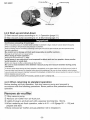
ANEST
I~TA
C€
JAa
ISO 9001
Jisa 9001
OMS Accredllation
R005
idealvac.com
Instruction Manual
I
LR104996
OJr prDl1K:I have SIt CSA
approval
tanadi~ standards
associatiool
(505)872-0037
idealvac.com
Oil-free Scroll Vacuum Pump
ISP-250C
ISP-500C
This instruction manual includes very important warnings, cautions and operating
procedure in order to operate this pump safely and efficiently.
Be sure to read this instruction manual thoroughly and fully understand before
operation.
After reading it, store it in a convenient place for immediate and future reading.
*
Before use, be sure to fill in the blank spaces below for future repair and after-service.
Serial No.
Who sold it to you
Purchase date
When you began
operation
Declaration of Conformity
We , ANEST rNATA Corporation
3176, Shinyoshida-cho, Kohoku-ku, Yokohama 223-8501, Japan
declare in our sole responsibility that the products
Type : Scroll Vacuum Pump
Models
ISP-250C
3-phase ,200/ 208/ 230/ 380/ 400/ 415/ 460V, 50/ 60Hz
1-phase , 100/ 1151200/ 230V, 50/ 60Hz
ISP-500C
3-phase ,200/ 208/ 230/ 380/ 400/ 415/ 460V,50/ 60Hz
1-phase , 100/ 1151200/ 230V, 50/ 60Hz
Note : 1-phase motor provides thermal protector.
to which this declaration applies, complies with these normative documents:
98/ 37/ EC : Machinery Directive
EN 1012-2:1996: Compressors and Vacuum Pumps-Safety
Requirements, Part 2: Vacuum Pumps
This Declaration is based on :
Third party testing, performed by the Notified Body
TUV Rheinland Product Safety GmbH - Am Grauen Stein - D-51105 Koln
TamirtSULtiioka ,
Manager of Vacuum Pump Dept
Jan, 28, 2008 YOKOHAMA
Date and Place
Important information
~~~~~~~~~~
Be sure to read this instruction manual to understand how to operate equipment
correctly. Only operators, who fully understand warnings, cautions and instructions,
are to operate the equipment. Improper operation (mishandling) can cause serious
bodily injury, death, fire or explosion.
G
Store this manual in a convenient place for immediate and future reference .
[~~~g:ar~iri~:~!~i:!
· The safety instructions given in this manual are the minimum operating requirements.
Follow all national or municipal laws and regulations pertaining to fire , electricity, and
other safety regulations, as well as corporate regulations.
· Pay special attention to items which are shown by the below marks and symbols.
· Symbols and marks have the following meanings.
Examples of marks
it
it
WARNING
Indicates a potentially hazardous situation which, if not
avoided, may result in serious injury or loss of life.
CAUTION
Indicates a potentially hazardous situation which, if not
avoided, may result in minor or moderate injury or property
damage.
Examples of symbols
&
Indicates [Beware] . We will explain briefly in or near the symbol.
(The example on the left is [Beware of electric shock]).
@
Indicates [Prohibited action] . We will explain briefly in or near the symbol.
(The example on the left is [Do not touch]) .
e
Indicates [Required action]. We will explain briefly in or near the symbol.
(The example on the left is [Be sure to ground]) .
.
* We shall not be responSible for any .Injury
or damage caused by disregard of
warnings, cautions or instructions.
Supplementary notes
Important
Indicates notes which we ask you to observe. They are helpful to
achieve full performance and functionality of the equipment.
-1-
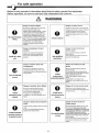
For safe operation
~~~~~~~~~~
Below is very important information about how to safely operate the equipment.
Before operation, be sure to read and fully understand the contents.
WARNING
o
Be careful about
lifting
Danger of cargo collapse
Danger of electric shock
Be careful 10 install vacuum pump using
motor handle (ISP-250C mass
25kgs/1-phase, 23kgs/3-phase), o r using
molor eyeboll and crane with sufficient
allowable load capacity (ISP-500C mass
44kgs/1-phase, 38kgs/3-phase) while
paying allentlon to stability 01 suspended
load. II not , it can cause damage, failure
or bodily injury from falling cargo due to
Install In an area which is not exposed to
moisture such as rain or steam . If moisture
comes Into and tact with the electric
source connection, it can cause fire or
bodily injury due to short-circuit or electric
shock.
o
Avoid moisture
hOisting failure, or by being caught
between suspended cargo and other
material.
o
Install at a safe
site
Danger of explosion. fire and
o
accident
Install in an area free from explosive,
fl ammable or corrosive substances.
If not, it can cause explosion, fire or
Ask qualified
electrician
accident
Danger of electric shock and
o
entang lement
Be sure to tum off electric source on
building site before wiring. II not, it can
cause electric shock or bodily injury due to
turning objects.
Install
overcurrent
protective device
Turn off electric
source
o
Install
emergency stop
switch
o
o
Danger of accident, fire or failure
Be sure to install an electric source
emergency stop switch (or protective
device that can urgently stop).
Danger of
short~ircuit
and
electri c shock
Ask a qualified electrician to perform
electric wiring .
If not, short-circuit or electric shock can
cause fire or bodily injury.
Danger of accident, fire and
failure
Be sure to install protective device to
protect cirCUitry.
We recommend overcurrent protective
device (rated 15A for IS P-250C and rated
15A for ISP-50OC (rated 20A
100/1 15V/lphase») to protect branch
circuit.
11 equipment is not stopped in an
emergency, it can cause accident, fire or
failure.
Danger of fire and electric shock
Install short circuit protective device.
If not, it can cause bodily injury due to fire
or electric shock.
Install short
circuit protective
device
If equipment Is not stopped in an
emergency. it can cause accident. fire or
failure.
short~ircuit
Danger of electric fire and electric
Danger of
shock
electric shock
Install overload protective device to protect
motor.
If not, it can cause bodily injury due to
electric fire or electric shock.
Install overload
protective device
to protect motor
o
Be careful about
wiring
-2-
and
We recommend an electric source cable
of more than 2mm2 {more than rated
10Al1 phase 7A13phase for ISP-250C and
more than rated 18A11phase 15A13phase
for ISP-500cl cross section area for
electric source cable and ground cable. Be
careful to avoid voltage drop considering
local situation.
If not, it can cause a short-circuit fire and
may result in bodily injury from electric
shock.
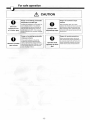
For safe operation
~~~~~~~~~~
WARNING
I
Danger of short-circuit and
0
Use crimp-<;tyle
terminal
0
electric shock
Fit firmly proper round type crimp-styte
terminal 10 electric source cable using
crimp tool and connect to molor terminal
Protect cable
from being
pulled
section.
If nol, it can cause short-<:ircuit fire or
bodily injury from electric shock due to
Danger of short-<:ircuit and
electric shock
Be sure 10 fit cable-gland to hole of
6 20mm al motor terminal box.
II
not, it can cause short-ci rcui t fire o r
bodily injury from electric shock.
looseness or disconnection.
e
Danger of electric shock
Danger of explosion and ignition
Connect ground cable to ground terminal
in molor terminal box.
Do nol evacuate gas which is hazardous
10 humans o r explosive, flammable, or
(9
If not, 11can cause bodily injury from
electric shock.
Be sure to
ground
(9
Avoid foreign
matter
0
Change after
Never evacuate
hazardous gas
Danger of entanglement and
Danger of ele ctric shock and
foreign matter dispersal
entanglement
Never put finger or foreign mailer Into air
hole of fan cover, air hole of motor or
clearance between FS(1) and FS(2)
cooling fins.
If done, it can cause bodily injury from
entanglement with turning section, or
foreign matter dispersal.
(9
Never alter
0
Danger of failure and bodily injury
Change
pump is
vacuum
vacuum
alr-flush port only after vacuum
stopped. If you change it during
pump operation , it can cause
pump failure and bodily Injury.
Conduct
periodical
vacuum pump is
Danger of failu re and bodily injury
Conduct periodical maintenance and
inspection.
If not, It can cause Insufficient
performance, lallure 01vacuum pump, and
bodily injury.
inspection
Danger of burns
Danger of electric shock
S
Conduct maintenance and Inspection only
after vacuum pump becomes cool enough.
Maintenance and inspection soon after
vacuum pump stops can cause burn injury.
Be careful about
high temperature
Be sure to conduct maintenance and
inspection aft er you lurn off electric
source. If not, it can cause bodily injury
from electric shock or turning object.
Turn off electric
source
0
Danger 01 accident, fa ilure and
0
Do not remove or alter safeguards or
insulation parts.
If done, it can cause bodily injury from
electric shock or turning section and it
can cause deteriorated performance and
operating tiletlme, and invalidate
guarantee.
maintenance and
stopped
&
corrosive. Do not evacuate with
substances containing chemicals,
solvents , and powders.
If done, it can cause failure or bodily
injury by gas, explosion or ignition.
shorter operating lifetime
Ask specialist 10 perform repairs.
Defective repairs can cause accident,
failure or shorter operating lifetime.
With a thermal
protector
[Only
singlellhase
motor)
Ask specialist to
perform repairs
-3-
Danger of restart
Be sure to switch off electric source before
maintenance or inspection.
Single-phase motor has a thermal
protector.
Vacuum pump restarts become cool
without warning after vacuum pump.
For safe operation
~~~~~~~~~~
CAUTION
o
Use at
designated
temperatu re
o
Danger of overheating
Danger of overheating
Operate at ambient temperature of 5"C40"C.
Operating al a temperature range other
than that designated can cause accident,
failure or bodily injury such as burns due to
overheating.
Install in a well""""'lentilated area. Poor ventilation
can disrupt cooling and cause accident, fai lure or
bodily injury such as burns since this vacuum
pump is an air-cooled type.
Pay attention
to
ventilation
o
Danger of dust
Be sure site is free from dust.
Sucking in of dust can cause failure.
Install on a
s olid , level
floor
Avoid dust
o
Inspect cause of
problem
o
Prevent fore ign
matter from
entering
o
Start or stop
after closing
isolation valve
Be sure to Install on solid and level floor (less IhCin
5D inclination).
Uneven installation can cause fa ilure and
movement of vacuum pump. If installation floor is
unstable, fix pump base with 4-0 11 holes of pump
leg (ISP-25OC) or 4-M 10 tap section pump base
(ISP-50OC) .
Dang er of overheating
Motor burnout
Inslall where equipment is not exposed to
direct sunlight.
Vacuum pump exposed to direct sunlight
can overheat, resulting in failure.
Belore doing any wiring , check electric source and
vollage. Single-phase is a multi vollage type of
AC 100V/AC200V. Three-phase is a multi voltage
type of AC200V!AC400V. Voltage can be changed
at terminal block. This !;1um!;1 is wired to 200V
when delivered to you . Check your electric source,
vollage, and wire correctly to terminal block.
Impruper wiring and Incorrect voltage can cause
motor burnout.
0
Avoid direct
sunlight
o
Danger of unbalance
Check voltage
Danger of probl em recurrence
o
and failure
If protective device or thermal protector
activates, be sure to tum oft electric
source and inspect causes to solve the
problem. Do not operate until problem is
solved. Operation while problem is left
unsolved can cause problem recurrence
and fa ilure.
Remove blank
flange
o
Danger of foreign matter entering
inlet
When checking turning direction, be
careful not to enter foreign matter into an
inlet. Foreign mailer entering inlel can
cause failure.
Pay attention to
exhaust
resistance
Danger of ex hau st d isruption
Remove blank flang e from Inlet and outlet.
Operation with blank flange being filled can disrupt
exhaust or cause blank flange to Ily by exhaust
Impetus, resulling in accident, fa ilure, or bodily
Injury from contact with flylng objects.
Dang er of exhaust disruptio n
When connecting exhaust piping to vacuum pump
and when combining piping with another vacuum
pump. pay allention to piping size and length so
that it does not cause exhaust resistance. Exhaust
resistance can disrupt air flow, resulting in fai ture
and over-currenl.
Danger of vacuum break and
Danger of abnormal sound and fa ilure
pollution
Open inlet to atmosphere lor about 5 seconds
before restarting vacuum pump.
II not, it can unbalance temperature Inside vacuu m
pump, re sulting in fa ilure.
Be sure to close isolation valve between
vac uum pump and vacu um system
(chamber) during startup and stop.
Start-1Jp or stop with isolation valve in lhe
open position can draw back gas and
debris attached to inside of pump to
vacuum chamber due to pressure
differential, resulting in vacuum break and
pollution on vacuum chamber side.
-4-
o
Open air
inlet
For safe operation
CAUTION
o
Beware
temperature
of intake gas
o
Beware of intake
gas volume
Danger of exceeding permissible
o
temperatu re of intake gas
If intake gas temperature is over SO"C , be
sure to install a chiller or trap between
vacuum pump and vacuum chamber so
thai gas intake temperature of vacuum
pump keeps below 50"C . If nol, vacuum
pump temperature can increase, resulling
in failure.
Caution after
exhausting vapor
o
Danger of exceeding permissible
Intake gas volume
When sending N2 gas or dry air into
air-llush port, pressure should be the
Operate while
opening air41ush
port
same as atmospheric pressure and flow
rate should be less than 10NLJmin.lf not,
il can increase pressure inside vacuum
pump, resulting in failure .
-5-
Danger of Insufficient vapor
exhaust
After evacuating vapor, do air-flush
operation lor at least one hour. II you close
air-flush port or stop vacuum pump soon
after evacuating vapor, condensed water
will remain inside vacuum pump which will
cause failure.
Danger 01 remaining moisture
When evacuating moisture, be sure to
open air-flush port (air-flush operation) . If
you evacuate vapor while air-flush port Is
closed , condensed moisture will remain
inside vacuum pump and cause fa ilure.
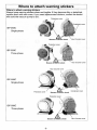
Where to attach warning stickers
Where to attach warning stickers
Always keep warning stickers clean and legible. If they become dirty or detached ,
replace them with new ones. If you need replacement stickers, contact the dealer
who sold the vacuum pump to you.
~ Ccmd"ns,er
cover
ISP-250C
Single-phase
Hour Counter cover
ISP-250C
Three-phase
ofi!iec:tric shock
Hour Counter cover
Hour Counter cover
ISP-500C
Single-phase
Protection cover
o'iE;je;;~ric shock
Condenser cover
ISP-500C
Three-phase
Beware of';fect.ic shock
-6-
Hour Counter cover
Contents
Important information ............................................................................................................. 1
For safe operation ..........................................................................•........................................ 2
Contents ...................................................................................................................................... 7
1. Before use ............................................................................................................................... 8
1.1 Check the product ............................................................................................................ 8
2. Name and structure of each section .................................................................................. 11
3. Installation ............................................................................................................................. 12
3.1 Wiring ............................................................................................................................... 13
3.2 Test operation ................................................................................................................. 17
3.3 Connection to vacuum system (chamber) ................................................................... 18
4. Operation ............................................................................................................................... 19
4.1 Standard operation ......................................................................................................... 21
4.1.1 Start-up ...................................................................................................................... 21
4.1.2 Shut-down ................................................................................................................. 21
4.2 Air-flush operation .......................................................................................................... 22
4.2.1 Preparation ................................................................................................................ 22
4.2.2 Startup and shut-down ............................................................................................ 23
4.2.3 When returning to standard operation .................................................................. 23
5. Maintenance and inspection ............................................................................................... 25
5.1 Daily maintenance and inspection ........................................•••..................................... 25
5.2 Maintenance .................................................................................................................... 26
6. Problems and remedies ....................................................................................................... 27
7. Specifications ....................................................................................................................... 28
7.1 Specifications .................................................................................................................. 28
7.1.1 ISP-250C .................................................................................................................... 28
7.1.2ISP-500C .................................................................................................................... 29
7.2 Dimensions ...................................................................................................................... 30
7.2.1 ISP-250C .......................................•............................................................................ 30
7.2.2 ISP-500C .....................................................•.............................................................. 30
7.3 Performance data ............................................................................................................ 31
-7-
1. Before use
1.1 Check the product
• Check that the package is right-side-up before opening .
• Check that the model of the product is the same as the one you ordered.
How to read model name
l iSP : model
I
s
p
p
2
5
o
o o
5
C
C
S V
-T H
Displacement (swept volume)
250C : 250 L/min at 50Hz Motor
500C : 500 L/min at 50Hz Motor
Motor
S : Single phase
T : Three phase
Inlet direction
H : horizontal
V: vertical
I SP-5 00 C- TH
I S P- 5 00 C-S H
I S P - 500 C - TV
I SP - 25 0 C - T V
I S P - 5 00 C - S V
IS P - 25 0 C-SV
• Check that there is no damage.
If there is any damage, contact either the dealer who sold it to you or us .
• Check the following accessories.
Instruction manual (this one)
Air-muffler for air-flush
(ISP-250C is attached to handle of motor. ISP-500C is attached to eyebolt of
motor.)
-8-
·ISP-250C
Vinyl bag
(Air muffler is contained inside)
~~
Serial number
Alphabetic
Numeric
Year of manufacture
·ISP-500C
Vinyl bag
(Air muffler is contained inside)
/"
Serial number
Alphabetic
Numeric
Year of manufacture
l8:: Please prepare electric source cords, crimp~tyle terminal, protective devices,
piping to inlet, and piping from outlet on customer side.
- 9-
Open package
6
WARNING
Danger of cargo collapse
Be careful to install vacuum pump using motor handle (ISP-250C mass
25kgs/l-phase, 23kgs/3-phase), or using motor eyebolt and crane with sufficient
allowable load capacity (ISP-l;OOC mass 44kgs/1-phase, 38kgs/3-phase) while
paying attention to stability of suspended load.
If not, it can cause damage, failure or bodily injury from falling cargo due to hoisting
failure, or by beinQ cauQht between suspended carQo and other material.
0
Be careful about
lifting
~ Instruction Manual
I
lLJ
Upper Cover
- - - - Oil-free Scroll Vacuum Pump
Box
-10-
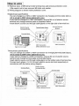
2. Name and structure of each section
·ISP-250C
Inlet NW25
Turning Direction Plate
Motor
Hour Counter
Air Flush Port (Rc 1181
Outlet NWt6
. ISP-500C
Inlet NW40
IN Plate
OUT Plate
NW25
Evebolt
Turning Direl
Fan Cover
Motor Base
- 11-
Hour Counter
Cooling Fan
Cooling Fan
, ~~ODO
o
Orbiting Scroll
0
OS
Fixed Scroll
FS(2)
Fixed Scroll
FS(1)
=
Structure of vacuum pump
=
3. Installation
6
WARNING
Danger of electric shock
Install in an area which is not exposed to moisture such as rain or steam.
If moisture comes into and tact with the electric source connecti on, it can cause fi re or
bodily injury due to short-<:ircuit or electric shock.
Danger of explosion, fire or accident
Install in an area free from explosive, flammable or corrosive substances.
If not, it can cause explosion, fire or accident.
0
0
Avoid moisture
Install at a safe site
6
CAUTION
Danger of overheating
Operate at ambient temperature of S"C-40"C .
Operating at a temperature range other than that designated can cause aCCident, fail ure
or bodily injury such as burns due to overheating.
0
Use at designated
temperature
Danger of overheating
Install in a well-venlil ated area (refer to below chart).
Poor ventilation can disrupt cooling and cause aCCident, failure or bodily injury such as
burns since this vacuum pump is an a i r~ oo l ed type.
Necessary ventilated air volume
ISP-250C
Over 4 m"'m in
[
ISP~OOC
I
Over 8 m"'min
- 12-
~
Pay atlen t ion to
ven t ila t ion
o
Danger of dust
Be sure site is free from dust.
Sucking in of dust can cause failure.
Av o id dust
Danger of unbalanc e
Be sure to install on solid and level floor (less than 5° inclination).
Uneven installation can cause failure and movement of vacuum pump. If installation
floor is unstable, fix pump base with 4-q, 11 holes of pump leg (ISP-250C) or 4~1 0 tap
section pump base (ISP-500C) .
o
Install on a
solid , level floor
MID tap section
less than 5~
incl ination
Danger of overheating
Install where equipment is not exposed to direct sunlight.
Vacuum pump exposed to direct sunlight can overheat, resu lting in failure.
o
.
Avoid direct
r h
Important
When bui lding vacuum pump into vacuum system, pay attention to space for maintenance,
ambient temperature and piping.
uestions, contact the dealer who sold it to ou or us.
31
.
. W·iring
6
WARNING
Danger of shorH:ircuit and electric shock
Ask a qualified electrician to perform electric wiring.
If not, short-drcuit or electric shock can cause fire or bodily injury.
0
Ask qualified
electrician
Danger of electric shock and entanglement
Be sure to turn off electric source on building site before wiring.
If not, it can cause electric shock or bodily injury due to turning objects.
S
Turn off electric
source
Danger of accident, fire and failure
Be sure to install protective device to protect circuitry. We recommend
overcurrent protective device (rated 15A for ISP-250C and rated 15A for ISP-500C
(rated 20A 1OO/115V/l phase)) to protect branch circuit.
If equipment is not stopped in an emergency, it can cause accident, fire or failure .
Danger of accident, fire or failure
Be sure to install an electric source emergency stop switch (or protective device
that can urgently stop)_
If equipment is not stopped in an emergency, it can cause accident, fire or failure.
Danger of fire and electric shock
Install short circuit protective device.
If not, it can cause bodily injury due to fire or electric shock.
0
Install overcurrent
protective device
0
Install emergency
stop switch
0
Install short circuit
protective device
-13-
Install overload protective device (refer to chart 1 on page 15) to protect
motor
If not, it can cause bodily injury due to electric fire or electric shock.
o
Install overload
protective device to
rotect motor
Danger of short~ircuit and electric shock
careful to avoid voltage drop considering local situation.
If not, it can cause a short-circuit fire and rna result in bodil in'u
Danger of short~ircuit and electric shock
from electric shock.
Fit firmly proper round type crimp-style terminal to electric source cable using
crimp tool and connect to motor terminal section.
II not, it can cause short~ircuit fire or bodily injury from electric shock due to looseness
or disconnection.
Danger of short~ircuit and electric shock
Be sure to fit cableilland to hole of 4> 20mm at motor terminal box.
If not, it can cause short-circuit fire or bodily injury from electric shock.
o
o
o
Be careful about
wiring
Use crimp-style
terminal
Protect cable from
bein
ulled
Danger of electric shock
Connect ground cable to ground terminal in motor terminal box.
If not, it can cause bodily injury from electric shock.
e
Be sure to round
Danger of restart
Be sure to switch off electric source before maintenance or inspection.
Single-phase motor has a thermal protector ..
Vacuum pump restarts become cool without warning after vacuum pump.
o
With a thermal
protector
[Only single-phase
motor
CSA Requirement
3 phase motor not protected - external protection in accordance with CE code, part I , must be provided.
Min. circuit ampacity of co nductor is
ISP-250C-I phase lOA /3phase 7A, ISP-500C- I phase ISA /3phase 15A
Max. branch circuit breaker is
ISP-250C - 15A, ISP-500C - 15A (I phase I OO/115V is 20A)
When you used this pump in Europe.
This vacuum pump must be equipped with a main disconnect device in accordance with requirements of
EN60204-1, clause 5.3.2. It is recommended to use a circuit breaker as rnain breaker which is suitable for
isolation according to EN60947-2 and is equipped with an operating handle which is lockable in OFF position
and com lies with the other re uirements of EN60204-I, clause 5.3.
~
CAUTION
Motor burnout
Before doing any wiring, check electric source and voltage.
Single-phase is a multi voltage type of ACIOOV/AC200V. Three-phase is a multi
voltage type of AC200V/AC400V.
Voltage can be changed at terminal block.
This I!uml! is wired to 200V when delivered to ]lou.
Check your electric source, voltage, and wire correctly to terminal block.
Improper wiring and incorrect voltage can cause motor burnout.
- 14-
0
Check voltage
o
Danger of problem recurrence and failure
If protective device or thermal protector activates, be sure to turn off electric
source and inspect causes to solve the problem.
Do not operate until problem is solved.
Ooeration while oroblem is left unsolved can cause oroblem recurrence and failure.
Inspect cause of
problem
This shows three-phase 200V connection for ISP-500C.
o
o
o
o
o
e
Electric Source
Ground Terminal
MS Bolt
Cable1lland
Activate the emergency stop by electric source
switch or protective device.
Avoid motor burnout by protective device (chart 1).
Use rated electric source cable and ground cable.
over rated 1ON11lhase, 7N31lhase for ISP-2S0C }
{ over rated 1BN11lhase, 1SN31lhase for ISP-500C
Use round type terminal.
Fit cable1Jland.
Connect ground cord to ground terminal.
Chart-1
Single-phase specifications
Voltage
Frequency
V
Hz
100
100
115
200
200
230
230
50
60
60
50
60
50
60
Three-phase specifications
Recommended
protective device (or
breaker) capacity
Voltage
Frequency
V
Hz
A
ISP-250C
ISP-500C
6.0
6.0
5.4
3.0
3.2
2.7
2.7
10.7
12.5
10.8
5.4
6.0
4.9
5.0
200
200
208
230
380
400
415
460
-15-
50
60
60
60
50
50
50
60
Recommended
protective device (or
breaker) capacity
A
ISP-250C
ISP-500C
1.8
2.2
2.2
2.2
1.1
1.1
1.2
1.2
3.1
3.2
3.0
2.9
1.8
1.8
1.9
1.7
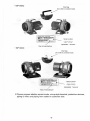
!How to wire !
Q) Remove 4pcs. of M5 bolt at motor terminal box and remove protection cover.
* Be careful not to lose removed M5 bolts and washer.
® Wiring diagram is shown inside protection cover.
Single1)hase specifications
You can change to a 100V or 200V connection by changing terminal plate (2pcs .) .
* It is wired to 200V when delivered to you.
If you want to change to a 1OOV connection , remove M4 nut of electric source
terminal and change terminal plate as illustrated below.
Insert electric source cord through cable1Jland on the right side of term inal box.
Electric Source
Terminal M4 Nu
Terminal plate (2pC5)
Ground Terminal
MS Bolt
o
o
Terminal Block
100V Connection
200V Connection
(When delivered to you)
Three1)hase specifications
You can change to a 200V or 400V connection by changing terminal plate (3pcs.).
* It is wired to 200V when delivered to you.
If you want to change to a 400V connection, remove M4 nut of electric source
terminal and change terminal plate as illustrated below.
Insert electric source cord through cable1Jland on the bottom side of terminal box.
Connect each phase L1-t.2-t.3 to each electric source terminal respectively in
accordance with the below wiring diagram .
Electric Source
I
Ground Terminal
MS Bolt
0
200V Connection
(When delivered to you)
- 16-
;---_____ 0
400V Connection
32T
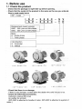
. est operation
~
CAUTION
Danger of exhaust disruption
Remove blank flange from inlet and outlet.
Operation with blank flange being fitted can disrupt air flow or cause blank flange to fly
by exhaust impetus, resulting in accident, failure, or bodily injury from contact with flying
objects.
Danger of foreign matter entering inlet
When checking turning direction, be careful not to enter foreign matter into an
inlet. Foreign matter entering inlet can cause failure.
0
Remove blank
flange
0
Prevent foreign
matter from enterin~
I Test operation I
CDOpen inlet and outlet
Remove blank flanges (2 places)
from inlet and outlet of
vacuum pump.
Blank Flange
~Check turning direction
O-fing
Open inlet, turn on electrical source
to start operating vacuum pump.
Vacuum pump turns clockwise
when viewed from motor side.
Di",cticm plate
Turning
Check that comes out of air outlet.
If air does not come out from outlet, vacuum pump of three-phase motor may turn
in reverse.
In that case, stop vacuum pump, turn off main electrical source and change 2 out
of 3 wires of electric source connection and change turning direction to correct one.
If you fit pump to vacuum system and control operation of vacuum pump by
-17-
remote control, first check pump itself for turning direction and then fit it to
vacuum system.
1m ortant
Vacuum pump turns clockwise when viewed f rom motor side.
II pump turns counter-clockwise. stop vacuum pump, turn off electrical source and change 2 out of 3 wires of
electrical source connection.
3.3 Connection to vacuum system (chamber)
Inlet of ISP-250C is NW25 and outlet is NW16.
Inlet of ISP-500C is NW40 and outlet is NW25.
~
CAUTION
Danger of exhaust disruption
When connecting exhaust piping to vacuum pump and when combining piping
with another vacuum pump, pay attention to piping size and length so that it does
0
Pay attention to
not cause exhaust resistance.
exhaust resistance
Exhaust resistance can disrupt air flow. resultinq in fai lure and over-current.
Important
Use lisolation valv~ between vacuum system and inlet.
Isolation valve is necessary to prevent the drawback of debris attached to the inside of vacuum pump into the
vacuum chamber durin start-up and
shut~own.
(We recommend the use of leak valve also). We recommend
the use of an utomatic val v as the isolation valve which closes during power failure in order to prevent
the drawback of debris inside pump into the vacuum chamber during power failure.
Use the clean connecting pipe between vacuum chamber and vacuum pump.
We recommend the use of a flexible tube between inlet of vacuum pump and vacuum chamber so that vibration
of pump does not transmit to vacuum chamber.
When connecting exhaust piping to outlet of vacuum pump, refer to the following size and length .
. It is recommended in the case of ISP-250C, max. 5m direct pipe length for exhaust pipe size NW16 (inner dia.16)
. It is recommended in the case of ISP."OOC, max. 15m direct pipe length for exhaust pipe size NW25 (inner
dia.25)
But if pipe length becomes longer. use a larger size exhaust pipe.
Make sure that exhaust piping is not clogged during pump operation.
Make sure that ressure at outlet does not exceed atmos
Leak
valve
<
Chamber
7
------------------,
Vacuum pump
x
,:
'------Jf-------i[><Jf-----'":-~_~--II ~~*'--T-,_ _0--lu~ct
Inlet
Isolation valve
(Automatic valve)
Outlet :,
- - _______ - - - - _____ I
ISP-250C
ISP~OOC
-18-
4. Operation
Be sure to use the procedure below to start up or shut down the pump .
. When you do not use air-flush device,
proceed 4.1 Standard operation [page 21] .
. When you use air-flush device,
roceed 4.2 Air-flush 0 eration
WARNING
Danger of explosion and ignition
Do not evacuate gas which is hazardous to humans or explosive, flammable, or
corrosive. Do not evacuate with substances containing chemicals, solvents, and
powders.
If done, it can cause failure or bodil in-u
lesion or i nilion.
.<S)
Do no t pump
· Toxic gas
· Explosive gas
· Flammable gas
· Co rrosive gas
· C hemicals
· Solv ent
· Po w der
Never evacuate
hazardous gas
· Water
. liqui d
* When evacuating vapor, operate in accordance with 4.2 lpage 221.
Danger of entanglement and foreign matter dispersal
Never put fi nger or foreign matter into air hole of fan cover, air hole of motor or
clearance between FS(l) and FS(2) cooling fins.
If done, it can cause bodily injury from entanglement with tu rn ing section, or foreign
0
maner~al.
\Y
Finger, foreign matter
Fing er, fo reign matter
Clearance between FS(1) and FS(2) cooling
fins
Avoid foreign matter
Air hole of fan cover
Air hole of motor
Danger of electric shock and entanglement
00 not remove or alter safeguards or insulation parts.
If done, it can cause bodily injury from electric shock or turn ing section and it can cause
deteriorated erformance and 0 eratin lifetime. and invalidate uarantee.
Danger of failure and bodily injury
Change
air~lush
port only after vacuum pump is slopped.
If you change it during vacuum pump operation, it ca n cause vacuu m pump failure and
bodily injury.
- 19-
Never alter
o
Change after
vacuum pump is
slo ed
~
CAUTION
Danger of exhaust disruptio n
Remove blank flange from inlet and outlet.
Operation with blank flange being fitted can disrupt exhaust or cause blank flange to fly
by exhaust impetus, resulting in accident, failure , or bodily injury from contact with flying
obiects.
Danger of vacuum break and pollution
Be sure to close isolation valve between vacuum pump and vacuum system
(chamber) during start-up and stop.
5tart"1Jp or stop with isolation valve in the open position can draw back gas and debris
attached to inside of pump to vacuum chamber due to pressure differential , resulting in
vacuum break and Dollution on vacuum chamber side.
Danger of abnormal sound and failure
Open inlet to atmosphere for about 5 seconds before restarting vacuum pump.
If not, it can unbalance temperature inside vacuum pump, resulting in failure .
Danger of exceeding permissible temperature of intake gas
If intake gas temperature is over SO'C . be sure to install a chiller or trap
between vacuum pump and vacuum chamber so that gas intake temperature of
vacuum pump keeps bet ow SO'C .
If not, vacuum pump temperature can increase, resulting in failu re.
Danger of remaining moisture
When evacuating moisture. be sure to open air-flush port (air-flush operation).
If you evacuate vapor while air-flush port is closed, condensed water will remain inside
vacuum pump and cause failure.
Danger of insufficient vapor exhaust
After evacuating vapor, do air-flush operation for at least one hour.
If you close air-flush port or stop vacuum pump soon after evacuating vapor, condensed
water will remain inside vacuum pump which will cause failure .
Danger of exceeding permissible intake gas volume
When sending N, gas or dry air into air-flush port. pressure should be the same
as atmospheric pressure and flow rate should be less than 10NL/min.
If not, it can increase pressure inside vac uum pump, resulting in failure.
0
Remove blank
flange
0
Start or stop after
closing isolation
valve
0
0
Open air inlet
Beware
te mperature of
intake gas
0
Operate while
opening air-flush
port
0
Caution after
exhausting vapor
0
Beware of intake
gas volume
Important
If it takes tim e to reach ultimate pressure of pump d uri ng initial operation (also operation
after pump has not been u sed f o r a long time).
Close inlet, and continue operation for 6-8 hours while opening inlet for 3-5 seconds to atmosphere 2-3
times per hour. During pump stoppage, moisture might have entered inside of pump and deteriorated
performance to reach ultimate pressure.
If pump has evacuated liquid such as water or high humid air (over 60%RH).
Moisture can deposit inside pump and cause pump failure. In that case, close isolation valve, and open inlet to
atmosphere for 3-5 seconds several times and exhaust moisture inside pump to outside.
If pump has continued operation around ultimate pressure o r continuously evacuated high
humid gas
Moisture can be condensed and remains inside pump, causing insufficient ultimate pressure and failure.
In that case, do air-flush
0
eration in accordance with 4.2
-20-
a e 22 .
4.1 Standard operation
4.1.1 Start-up
CD
Check that blank flange of outlet is removed.
(g) Close isolation valve in order to prevent the drawback of debris attached to the
inside of vacuum pump into vacuum chamber due to pressure differential,
resulting in vacuum break and pollution.
(Open leak valve if you use leak valve) .
® Turn on vacuum
pump .
@) Check start-up of vacuum pump and open isolation valve (close leak valve soon
after start-up if you use leak valve) and evacuate vacuum chamber.
Important
When continuously operating pump at around ultimate pressure (for example, using as fore
line pump of turbo molecular pump) ,
It can cause foreign matter or moisture to deposit inside pump, resulting in failure.
In that case, do air-flush operation or close isolation valve and open inlet to atmosphere for 3-5 seconds, 3- 5
times daily.
Be careful not to damage air-flush port (especially air-muffler section).
If not, it can cause failure.
When doing air-flush operation,
Noise level will increase (by 7-SdB).
Install pump in an area which is not exposed to debris such as iron powder, stone powder,
polish powder or wood dust.
Debris can clo air-muffler, undercuttin air-flush effect.
4.1.2 Shut-down
CD Be sure to close isolation valve in order to prevent the drawback of debris
attached to inside of vacuum pump into vacuum chamber during operation due to
pressure differential (open leak valve if you use leak valve).
(g) Turn off vacuum pump.
® Check shut-down of vacuum pump.
Important
Be sure to close isolation valve between vacuum pump and vacuum chamber during pump
shut-{jown.
If vacuum pump stops during air-flush operation, atmospheric air is drawn back from air-flush port to inside of
- 21-
4.2 Air41ush operation
This pump is equipped with air-flush port. Before evacuating vapor, read
precautions below completely and be sure to understand the contents.
iPurpose of air-flushi
Evacuating moisture or humid gas by vacuum pump can cause condensed water to
remain in pump. This remaining water can cause failure of ultimate pressure or
pump. Air-flush operation is necessary to exhaust the remaining water inside.
Air-flush operation does not only exhaust moisture but also restores ultimate
pressure .
* Vapor disposal volume is max. 25g/day, when doing air41ush operation(ambient temperature25°C,
humidity 60%RH) .
Important
Maintenance interval of this pump is based on clean gas applications The standard differs
when evacuating vapor.
You must shorten maintenance interval (5.2[page 26]) when evacuating vapor since vapor temperature, disposal
volume, disposal frequency and substances in vapor have an influence on pump operation. When evacuating
vapor, pay attention to ali WARNING, CAUTION and Important notes (4 [page 19]).
4.2.1 Preparation
Before starting air-flush operation, first stop vacuum pump and proceed in
accordance with the following procedure. Never try to do air-flush operation during
operation.
IFit air-mufflerl
CD Stop vacuum pump.
~ Remove plug from air-flush port with a spanner (nominal dia. 13mm).
®
Lightly fit the attached air-muffler to air-flush port.
?,:( Store the removed plug and do not misplace it.
ISP-250C
air-iTluffler
Remove plug
-22-
ISP-500C
Fit air-muffler ~
_ /
Remove plug
Air-ilush port
4.2.2 Start-up and shut-down
CD Start vacuum pump according to 4.1.1 Operation [page 21].
®
Stop vacuum pump according to 4.1.2 Shut-down[page 21].
Important
Continuous evacuating of humid gas
When evacuating vacuum chamber while humidity in chamber is high, moisture volume drawn into pump
differs according to temperature and pressure in chamber.
When pumping vacuum chamber containing humid gas, be sure to open air-flush port and operate pump
(air-ilush operation).
Be careful not to damage air-flush port (especially air-muffler section) .
Damage to air-ilush port can cause failure.
When doing air-flush operation
Noise level will increase (by 7-8dB).
Install pump in an area which is not exposed to debris such as iron powder, stone powder,
polish powder or wood dust.
Debris can clog air-muffler, undercutting air-ilush effect.
Be sure to close isolation valve between vacuum pump and vacuum chamber during pump
shut-<lown.
If vacuum pump stops during air-ilush operation, atmospheric air is drawn back from air-ilush port to inside of
vacuum pump, and vacuum on chamber side cannot be maintained. Be sure to close isolation valve between
vacuum pump and vacuum chamber to prevent the drawback of debris from vacuum pump into vacuum chamber
before stopping vacuum pump.
When 0 eratin with air-ilush OFF closed , 0 erate as er 4.2.3 a e 23 .
4.2.3 When returning to standard operation
Before starting air-flush operation, first stop vacuum pump and proceed in
accordance with the following procedure. Never perform this procedure during
operation.
IRemove air-muffle~
CD Stop vacuum pump.
® Remove air-muffler from
air-flush port.
@ Lightly fit plug to air-flush port with a spanner (nominal dia. 13mm).
* When restarting air-flush operation, refer to 4.2.1-4.2.2[page 22 prepare and start.
* Store removed air-muffler and pay attention not to misplace it.
-23-
23] and
ISP-250C
Fit plug
\
Remove ai r-muffler
ISP-500C
Remove air-muffler
Fit plug
~-
-24-
/
5 , Mam t enance an d'mspec f Ion
6
WARNING
Danger of failure and bodily injury
0
Conduct periodical maintenance and inspection.
If not, it can cause insufficient performance, failure of vacuum pump, and bodily injury.
Conduct periodical
maintenance and
inspection
~
Danger of burns
Conduct maintenance and inspection only after vacuum pump becomes cool
enough.
Maintenance and inspection soon after vacuum pump stops can cause burn injury.
Be careful about
high temperature
Danger of restart
0
Be sure to switch off electric source before maintenance or inspection.
Single-phase motor has a thermal protector.
Vacuum pump restarts become cool without warning after vacuum pump.
With a thermal
protector
[Only singlel'hase
motor]
S
Danger of electric shock
Be sure to conduct maintenance and inspection after you turn off electric source.
If not, it can cause bodily injury from electric shock or turning object.
Turn off electric
source
0
Danger of accident, failure and shorter operating lifetime
Ask specialist to perform repairs.
Defective repairs can cause accident, fai lure or shorter operating lifetime.
Ask specialist to
perform repairs
5.1 Daily maintenance and inspection
Conduct the following daily maintenance and inspection.
Items
Contents
-
Measures
Ask specialist to repair.
Abnormal sound
.- - -Abnormal vibration
Ask specialist to repair.
Abnormal temperature
Ask specialist to repair.
--
.-
Vacuum pump itself
..
-
- - - --- ~.-
Cooling fins are dirty or clogged
Cooling fan
Fan cover
.-
Smooth turning
Blow air, cleaning
Ask specialist to repair.
.-- - - -- ~--.-------- -~---~-~--
----
---~~-~- -- - - ----.----
Dirty, clogged, damaged
Blowing air, clean, Ask specialist
to repair.
Air;nuffler
Dirty, clogged
Replace
Exhaust valve
Dirty, clogged
Blowing air, clean
Electric source cable
Deteriorated
Replace
-25-
5.2 Maintenance
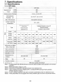
Maintenance interval is when arrives at earlier than either 1 year or 8,000 hr.
When maintenance interval has elapsed, be sure to contact our distributor who sold
it to you. This vacuum pump requires maintenance conducted only by our authorized
specialist. Never try to disassemble, reassemble or alter on user's side. We are not
responsible for any accidents caused by disassembly, reassembly or alteration which
was done by the user or non-specialist. As the table below shows average conditions,
shorten the maintenance interval and carry out maintenance if ambient and
operating conditions are unfavorable or severe. The table below is based on ambient
temperature 5-40°C and yearly average ambient temperature 25°C.
Maintenance interval differs from guarantee period.
The following parts are consumable and need to be replaced periodically.
Whenever somethi
with
ace them
I
Maintenance interval
W her e
t 0
inspect
Yearly or
hours
()"
Every 400 times
vapor pumping
hours
Bearing k~
grease/ 6
0
6
Tip seal set
6
0
6
Seal set
0
0
6
O-fing set
0
0
6
Exhaust valve set
0
0
6
Air-flush kit
0
0
0
Pin crank kit
6
6
6
Vacuum pump itself
Inside cleaning/6
Inside cleaning /6
Inside cleaning /6
• Replace
6 · • . Replace if something goes wrong .
Note1: Maintenance interval should be shorter than either the period or operating hours.
1h
Note 2 : When you want further maintenance and inspection after either the 6 year or 48,000
ple,~se contact our distributor who sold it to
Causes of failure
Shorten maintenance interval if conditions of installation or operation are unfavorable.
In particular, ambient temperature has a great influence on failure. Maintenance interval is based on an ambient
temperature 5-40"C and a yearly average ambient temperature 25"C.
Shorten the maintenance interval if temperature exceeds the foregoing . If not, it can cause fai lure.
Maintenance interval is not a guarantee period.
Exceeding maintenance interval
Operation exceeding maintenance interval increases risk of failure and accidents.
either the distributor who sold it to
-26-
or us.
6. Problems and remedies
If something goes wrong, refer to the following chart and remedy problems .
If you cannot solve your problems, please contact either our distributor who sold it to
you or us.
Problems
Causes
Remedies
Protective device (or breaker)
>* Inspect and repair.
activates.
Electric source cable is loose
Check connection.
Repair or replace.
or cut.
Voltage drops.
Check size and length of cable.
Motor malfunctions.
Motor does not rotate.
>* Inspect and repair.
Pump malfunctions.
>* Inspect and repair.
Foreign matter enters.
Motor protection gear
Air outlet is clogged.
activates.
Reset Ihermal protector.
>* Inspecl and repair.
Protective device (or breaker)
>* Inspect and repair.
activates.
Voltage drops.
Check size and length of cable.
Motor malfunctions.
>* Inspect and repair.
Pump malfunctions.
>* Inspect and repair.
Foreign matter enters.
Improper exhaust piping.
Check exhaust piping diameter and
Motor stops soon.
length.
Air outlet is clogged .
Remove blank flange from exhaust
outlet.
Motor protection gear
Air outlet is clogged.
activates.
Reset thermal protector.
>* Inspect and repair.
Air leaks from piping.
Check tightness of piping.
O-ring is damaged.
Replace.
Moisture and solvent are
Open inlet to atmosphere and operate
drawn.
for a few minutes and then close inlet
and operate for about 24 hours.
Ultimate pressure is
Do air-flush operation .
insufficient.
Install trap and filter.
Check wiring and voltage.
Number of motor revolutions
>* Inspect and repair.
drops.
>* Inspect and repair.
Pump malfunctions.
Connection becomes loose.
Tighten connection .
>* Inspect and repair.
The inslallation is not level.
Correct vacuum pump inclination within
5°.
Abnormal sound,
>* Inspect and repair.
abnormal vibration
Foreign matter enters pump.
>* Inspect and repair.
Motor malfunctions.
>* Inspect and repair.
Pump malfunctions.
>* Inspect and repair.
*
Contact our dlstrtbutor who sold it to you.
-27-
7. Specifications
7.1 Specifications
7.1.1 ISP-250C
Model
ISP-250C
Displacement
l./min
50Hz
250
60Hz
300
Ultimate pressure PalTorr)
;:;; 1.6
Leak tightness
I ;:;; 1.2x 10⁻² )
;:;; 1.0xl0" 1 ;:;; 1.0 x l0~)
Palmbar) • l./s
Max. inlet pressure
Atmospheric pressure
Ambient operating
5·C-40·C
temperature
Single-phase induction motOI 4P
Type
Totall y-enclosed
3iJhase induction motor 4P
Insulation Class B IP44
Totally-Enclosed
Capac it or s ta rl TP21 2
Insulation Class B IP44
Automatic Reset Type
Output
kW
0.4
~
~
Voltage
::;;
V
100
115
200
230
200
208
230
380
400
415
460
Rated
50Hz
4.8
-
2.6
2.4
1.6
-
-
0.9
0.9
1.0
-
current A
60Hz
4.8
4.3
2.8
2.4
1.9
1.9
1.8
-
-
-
1.0
Revolution
50Hz 1440
-
1430
1450
1420
-
-
1440
1440
1440
-
min-' Irpm)
60Hz 1710
1740
1700
1730
1660
1660
1690
-
-
-
1720
(note2)
;:;; 58
;:;; 66
Noise level 1m dB(A)
With air-llush ON
Inlet connection
NW25
Outlet connection
NW16
Direction of inlet
Vertical
Dimensions mm
LxWxH
Mass
kg
400x252x336
370x252x336
25
23
Air-{;ooled
Cooling system
With hour counter and air-llush
Others
Notel: Pumping speed and ultimate pressure remam the same dUring alr-llush operation and standard
operation.
Note 2 : Motor permissible voltage is ±10%.
Note 3 : Noise level is measured at ultimate pressure in an anechoic room.
Note 4 : Vapor handling is less than 25g/day (25·C , humidity 60%RH) during air-llush operation.
Air-llush volume is 10l./min.
Note 5 : Pump is standard operation with 200V connection specifications when it is delivered to you.
Note 6 : Three phase Motor is not equipped with motor protection gear. Be sure to fit protective device.
-28-
7.1.2 ISP-500C
Model
ISP-500C
Displacement
l./min
50Hz
500
60Hz
600
(~7 . 5 x 1O")
~1
Ultimate pressure Pa(Torr}
Leak tightness
~ 1.0 x 1O" { ~ 1 .0x1O"' }
Pa{mbar} . l./s
Max. inlet pressure
Atmospheric pressure
Ambient operating
5°C-40°C
temperature
Singte-phase induction motor 4P
3-phase induction motor 4P
Tolally-enclosed
Type
Totally-£nclosed
Insulation Class B IP44
Capacitor start TP21 2
Insulation Class B IP44
Au toma1ic Reset Type
Output
kW
0.6
0
15
Voltage
~
V
100
115
200
230
200
208
230
380
400
415
460
Rated
50Hz
8.5
-
4.3
3 .9
2.7
-
-
1.57
1.57
1.63
-
current A
60Hz
10.0
8.6
4.8
4.0
2.8
2.6
2.5
-
-
-
1.47
Revolution
min-' {rpm}
50Hz 1430
-
1430
1450
1460
-
-
1470
1470
1470
-
60Hz 1660
1720
1690
1730
1740
1760
1760
-
-
-
1770
(note2)
Noise level 1m dB(A)
;;; 62
;;; 60
With air-.flush ON
~ 70
~ 68
I n let connection
NW40
Outlet connection
NW25
Direction of inlet
Dimensions mm
LxW xH
Mass
kg
Horizontal
(vertical)
443 x328x372
(443 x290 x397)
372x328x372
(372 x292 x 397)
44
38
Cooling system
Air-<:ooled
Others
With hour counter and air-.flush
Note1 : Pumping speed and ultimate pressure remain the same dUring aor-.flush operation and standard
operation.
Note 2 : Motor permissible voltage is ±10%.
Note 3 : Noise level is measured at ultimate pressure in an anechoic room.
Note 4 : Vapor handling is less than 25g/day (25"C, humidity 60%RH) during air-.flush operation .
Air-.flush volume is 10l./min.
Note 5 : Pump is standard operation with 200V connection specifications when it is delivered to you .
Note 6 : Three phase Motor is not equipped with motor protection gear. Be sure to fit protective device.
- 29-
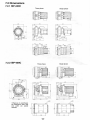
7.2 Dimensions
7.2.1 ISP-250C
Three phase
Single phase
,,,
'"
r
52
"
7.2.2 ISP-500C
32'
(29)
Single phase
Three phase
."'"
I
;L I
·1"
~
~
"
•
N
"
'"
"
~
~-
~
' .Hl0
*
Figutures in parentheses
are dimensions when Inlet
and outlet
vertically
,,,
are
placed
. .. -"
-[]
"
"
'"
-30-
•
J
'·M
o
~-
I
0
~
.
11
'"
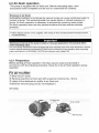
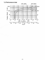
7.3 Performance data
ISP-250C
I II III
Wi
100 0
ISP-500C
~ll
II IIII
~" 1 1 1 000
~
~
c:
E
"-l
~
~
:;-
10 0
=
#I-
fttJ/-
1J
~
Q)
Q)
a.
W
~ 100
10
10
C>
c:
a.
E
:::l
a..
1
10 -,
" ",!
10- 3
10
0
,
10
5 10 3
10
Inlet Pressure
(Pa)
:>
2
" ~" ' ;0~2 ' ' ~ " ';O-~ " ~ " ';O ~ " ~ "';O ;
(Torr)
- 31 -
:>
10
4
:>
1
10
5