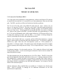
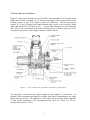
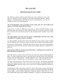
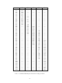
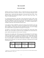
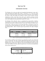
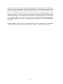
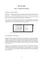
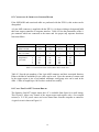
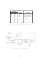
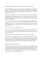
1
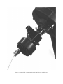
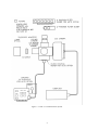
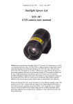
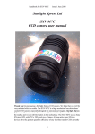
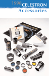
MODEL PFE-1
CCD/TELESCOPE ADAPTER
Technical Manual and User’s Guide
OPTEC, Inc.
OPTICAL AND ELECTRONIC PRODUCTS
[email protected]
http://www.optecinc.com
199 Smith St.
Lowell, MI 49331
U.S.A.
(616) 897-9351
(616) 897-8229 FAX
Figure 1-1. Model PFE-1 shown with Lynxx PC and Celestron 8" Telescope.
TABLE OF CONTENTS
Revision 6 - January 2000
Section
1.0
2.0
3.0
4.0
5.0
6.0
7.0
8.0
INTRODUCTION. . . . . . . . . . . . . . . . . . . . . . . . . . . . . . . . . . . . . . . . . . . . . . .
..
THEORY
OF OPERATION. . . . . . . . . . . . . . . . . . . . . . . . . . . . . . . . . . . . . . . .
.
2.1
Purpose of the PFE-1. . . . . . . . . . . . . . . . . . . . . . . . . . . . . . . . . . . . . . . .
..
2.2 Basic
Mechanical Design. . . . . . . . . . . . . . . . . . . . . . . . . . . . . . . . . . . . . .
.
INSTALLATION
PROCEDURES. . . . . . . . . . . . . . . . . . . . . . . . . . . . . . . . . . .
.3.1 Mounting the PFE-1. . . . . . . . . . . . . . . . . . . . . . . . . . . . . . . . . . . . . . . . .
..
3.2 Mounting
Kits for CCD Cameras. . . . . . . . . . . . . . . . . . . . . . . . . . . . . . .
.
3.3 Reticle alignment. . . . . . . . . . . . . . . . . . . . . . . . . . . . . . . . . . . . . . . . . . . .
.
TROUBLE-SHOOTING
GUIDE. . . . . . . . . . . . . . . . . . . . . . . . . . . . . . . . . . . .
.JOHNSON UBVRI FILTERS. . . . . . . . . . . . . . . . . . . . . . . . . . . . . . . . . . . . . .
..
WING
FILTERS. . . . . . . . . . . . . . . . . . . . . . . . . . . . . . . . . . . . . . . . . . . . . . . .
.STRÖMGREN
.
FILTERS . . . . . . . . . . . . . . . . . . . . . . . . . . . . . . . . . . . . . . . . .
..
PFE-1A
AUTOMATIC OPTION . . . . . . . . . . . . . . . . . . . . . . . . . . . . . . . . . . .
.8.1
.
Physical Characteristics. . . . . . . . . . . . . . . . . . . . . . . . . . . . . . . . . . . . . . .
.
8.2 Determining
Filter Position . . . . . . . . . . . . . . . . . . . . . . . . . . . . . . . . . . .
.
.
8.3 Connecting & Operating the Stepper Motor. . . . . . . . . . . . . . . . . . . . . . .
..
8.4 Using
the SAA1027 Stepper Driver . . . . . . . . . . . . . . . . . . . . . . . . . . . . .
.
APPENDICES
A.
PFE-1A Mounting Kit Instructions . . . . . . . . . . . . . . . . . . . . . . . . . . . . .
.
i
Page
1
3
3
4
7
7
7
7
9
11
15
16
18
18
18
19
19
A-1
LIST OF FIGURES
Figure
1-1
1-2
2-1
8-1
PFE-1 shown with Lynxx PC and Meade 8" Telescope. . . . . . . . . .
PFE-1 CCD Photometer System and Accessories. . . . . . . . . . . . . .
Cross-Sectional View of the PFE-1 mounted with CCD camera. . .
Typical Stepper Control Curcuit Using the SAA1027. . . . . . . . . . . .
Page
Cover
2
4
20
LIST OF TABLES
Table
5-1
5-2
5-3
5-4
6-1
7-1
7-2
8-1
8-2
8-3
Physical Characteristics of Optec UBVRI Filters. . . . . . . . . . . . . .
Standard UBVRI Response Functions According to Johnson. . . . .
UBVRI Response Functions of Optec Filters. . . . . . . . . . . . . . . . .
Filter Transmission and Detector Responsivity in A/W. . . . . . . . .
Specifications for Wing Filters. . . . . . . . . . . . . . . . . . . . . . . . . . . .
Optical Specifications of the Strömgren Filters. . . . . . . . . . . . . . . .
Physical Specifications of the Strömgren Filters. . . . . . . . . . . . . . .
Specifications for Model PF35-48C Stepper Motor. . . . . . . . . . . .
Function and Color Code of Motor Wires. . . . . . . . . . . . . . . . . . .
. Number and Function for Motor Control Cable Connector. . . .
Pin
ii
Page
11
12
13
14
15
16
16
18
19
20
SECTION 1.0
INTRODUCTION
The recent advent of affordable astronomical CCD cameras has opened whole new
opportunities in the area of stellar and extended object photometry. The small format
CCD cameras now being manufactured by companies such as Meade and Santa
Barbara Instrument Group are examples of the new low-cost cooled-chip astronomical cameras. Regrettably, with these cameras alone it is difficult to find and
center objects, focus the camera, and, most importantly for photometry, insert filters
into the light path. Optec has developed the Model PFE-1 Photometric Front-End to
provide the much needed coupling between telescope and CCD camera head. With
the PFE-1, easy and accurate photometric quality imaging is finally possible.
The Model PFE-1 was originally designed specifically for the Lynxx PC CCD camera
systems, but has now been adapted for many small format cameras as well. Consult
the current price list for additional adapter kits for new cameras supported by the
PFE-1.
The PFE-1 is a complete system with many filter options, a 0.5x telecompressor and
3x tele-extender options, and a fully automated filter slider option.
1
Figure 1-2. PFE-1A CCD Photometer System.
2
SECTION 2.0
THEORY OF OPERATION
2.1 PURPOSE OF THE MODEL PFE-1
Two of the most serious limitations to doing photometry with the small format CCD cameras
are small field sizes and lack of a convenient way to insert photometric filters into the light
path. The PFE-1 provides an off-the-shelf solution to both these problems.
The TC-211 CCD chip used in the SBIG ST-4 and Lynxx PC series cameras has an
array of 165 pixels by 192 pixels. The chip is only about 1/10th inch square and therefore
offers a very small field-of-view. Finding and centering an object can be difficult without
some sort of pre-viewer. Off-axis guiders do not provide full-field views and are of limited
use. However, the eyepiece of the PFE-1 provides a full field view (approximately 0.4° with
an 8" f/10) and an illuminated reticle which exactly defines the CCD detector field of view.
Locating and centering an object with the PFE-1 is as simple as looking through the
eyepiece, positioning the telescope, and opening the flip-mirror.
Because of the limited field size, to properly perform differential photometry a separate
image is often required for both the check and comparison stars. To effectively double the
field-of-view, Optec offers the 0.5X telecompressor (stock no. 17610) mounted in a
removable 1¼" telescope coupler. This option can be used with light cones of f/10 or higher
without vignetting when using cameras having CCD's no larger than about 3.3mm by 2.4mm
size.
For planetary imaging, a 3x tele-extender (stock no. 17611) triples the effective focal length
of the telescope system. A well corrected negative achromat is used in the tele-extender for
unparalled planetary images.
The other important issue for any photometric use of a CCD is filters. The PFE-1 has a filter
port directly behind the flip-mirror which allows the use of ½" diameter photometric filters.
The standard PFE-1 requires the filters to be mounted in 2-position filter sliders (stock no.
17050). The automated version PFE-1A includes a stepper motor and can use the 6-position
filter sliders which are controlled by the SSPCARD and computer. See Section 9.0 for full
details of the automated option.
Johnson, Strömgren, Wing, and Hß filters are available in ½" diameter sizes directly from
Optec. Refer to Sections 5.0 through 8.0 for additional information on our filter
specifications for photometry.
3
2.2 BASIC MECHANICAL DESIGN
Figures 2-1 shows cross-sectional views of the PFE-1 when mounted to a CCD camera head.
Light enters the PFE-1 through the 1¼ inch telescope adapter and is directed either to the
focusing eyepiece or the CCD sensor by means of a flip-mirror. The focusing eyepiece
consists of a 1-inch (25.4mm) focal length Ramsden and a reticle with a precisely etched
square that defines the CCD field of view. A green LED illuminates the reticle from the
side. After a star is positioned in the reticle, the flip mirror is rotated to expose the CCD.
An exposure may now by made using the camera's control software.
Figure 2-1. Cross-sectional view of the PFE-1A mounted to a CCD camera.
The removable 1¼-inch telescope coupler attaches to any standard 1¼ inch focuser. An
optional 2-inch focusing mount adapter is available from Optec for attachment to the larger
format telescope focusers. The standard 1¼-inch coupler can be replaced with a removable
1¼-inch coupler containing a 0.5X telecompressor lens (stock no. 17610) or a 3X teleextender lens (stock no. 17611).
4
On the bottom of the PFE-1 flip mirror/eyepiece assembly is an input jack for the 12 VDC
required to provide power to the reticle LED. The external DC power supply adapter should
be plugged in before operation. To adjust the reticle brightness on the PFE-1, use a small
screwdriver to turn the pot next to the power input jack. The PFE-1A has an adjustment
knob to facilitate changing the reticle brightness.
For the PFE-1, a two-position filter slider is mounted between the flip mirror and the CCD.
Any pair of filters selected by the user before delivery can be mounted in the slider. Since
the slider is easily pulled out of the unit, sliders with other combinations of filters can be
inserted.
The automated PFE-1A uses a 6-position filter slider made of a special self-lubricating
material. A rack mounted on the slider meshes with a bevel gear connected to the stepper
motor which is mounted beneath the main flip-mirror block. The 6-position filter sliders can
be pulled out and replaced, but this procedure requires removing one of the filter slider
covers. By replacing these larger capacity sliders, other photometric filter systems can be
accommodated.
For most variable star work, a single slider with B and V filters is recommended to begin
with. All Optec filters are ½" (12.7mm) in diameter and 7mm thick. See Section 6.0 for a
description of the standard UBVRI filter system, Section 7.0 for a description of the MA,
MB and MI Wing filter set, and Section 8.0 for a description of the Strömgren uvby fourcolor system.
For observations which do not require a photometric filter, the Clear filter should used to
insure that the proper optical distance is maintained. Without the Clear filter, the eyepiece
would no longer be parfocal with the CCD and stellar images will be out of focus on the
CCD sensor.
For tri-color imaging (RGB), the Johnson B, V, and R filters can be used. Since each filter
blocks the infrared, no separate IR blocking filter is needed.
To adapt the Model PFE-1 to the various CCD camera heads available, Optec has designed a
number of special mounting kits. These kits provide all the necessary hardware including
mounting screws and allen keys for adapting the PFE-1 to a particular camera head. Refer
to Appendix A for full instructions regarding the mounting kits. The reticle alignment
procedure is detailed in Section 3.3 below.
Owners of the Lynxx PC, MC, or Lynxx 2 CCD camera systems should order mounting kit
stock number 17612. The standard combination 2"/1¼" telescope coupler provided by
SpectraSource Instruments is replaced with a stainless steel camera mounting adapter. This
special camera mount is secured to the camera head with three small screws. Specify
mounting kit number 17613 for use with a standard C-mount camera. This kit includes a
dovetail plate and the (approx.) 1” diameter male C-thread for easy attachment of a typical
C-mount video camera.
5
Mounting kit stock number 17614 will adapt the Santa Barbara Instrument Group's Model
ST-4 CCD camera to the PFE-1. The 1¼" telescope mount of the ST-4 includes a small
cover window and O-ring seal. Mounting kit number 17614 includes a special spacer which
contains a replacement cover window and O-ring seal. The stainless steel camera mount
then attaches to this spacer and the PFE-1 attaches to the camera mount. Again, all
mounting screws and tools are included with the mounting kit. To gain additional field of
view, the eyepiece mount used on the PFE-1 is slightly shorter for the ST-4. Be sure to
specify mounting kit number 17614 when ordering a PFE-1 for use with the ST-4.
Mounting kit stock number 17615 will adapt the Santa Barbara Instrument Group's Model
ST-5 CCD camera to the PFE-1. Like the Lynxx-2000, the ST-5 uses the TC-255 CCD and
must also have a rectangular reticle mounted in the focusing eyepiece of the PFE-1.
Otherwise, mounting kit number 17615 is identical to number 17614 and installs in the same
manner.
Specify mounting kit number 17616 to adapt the PFE-1 to Meade's Pictor 416 camera. The
Pictor 416 uses a Kodak KAF-0400 CCD with a rectangular imaging area. This CCD
features 768 x 512 pixels and is 6.90 x 4.60mm in size. When this kit is ordered, the
rectangular reticle installed in the PFE-1 matches this shape and size. The stainless steel
mount simply screws into the camera head and replaces the existing 1¼" telescope adapter.
Owners of the Celestron/SBIG PixCel 255 camera should specify mounting kit number
17618. The PixCel adapter is unique in that it allows the CCD camera to be removed from
the PFE-1 much like a standard camera lens. Bot focus and rotational alignment are
maintained with camera removal and attachment. This feature allows the PixCel camera to
be easily used with both the PFE-1 and the MAXfield 0.33X telecompressor product.
Changing between the PFE-1 flip-mirror and the MAXfield telecompressor is as easy as
changing a 35mm camera lens.
With the proper CCD camera mounting kit, the PFE-1 flip-mirror/eyepiece assembly is then
attached to the camera. A dovetail mount on the camera side and four setscrews on the
PFE-1 side provide adjustment in the X and Y directions. Reticle alignments are easily done
on the Optec optical bench or at the telescope.
The CCD camera head completes the portion of the CCD photometer which is installed on
the telescope. Typically, a multiconductor cable will connect the CCD photometer head to
the host computer or control box. Refer to the user manual provided with your camera or
control software.
Optec will install the PFE-1 with any camera at no charge and will perform the reticle
alignment on an optical bench for initial purchases. Subsequent reticle alignments can be
performed for a nominal charge. The entire camera outfit including camera head, control box
or interface card, and software should be sent to Optec for installation. Consult the current
price list for additional cameras supported. Contact Optec for adapting the PFE-1 to any
cameras not shown on the current price list.
6
SECTION 3.0
INSTALLATION PROCEDURES
3.1 MOUNTING THE PFE-1
Installation of the PFE-1 to one of the cameras should be done in a clean area free of dust
and other contaminants. The procedure is not difficult and all necessary tools are provided
with the mounting kits. However, as with any delicate optical device, care should be taken
when handling the camera.
For first time buyers who prefer not to attempt mounting the PFE-1, Optec will perform the
installation and reticle alignment free-of-charge. This will, of course, require sending the
camera head and control electronics to Optec. Re-alignments will also be performed for a
nominal fee. Call Optec for details.
3.2 MOUNTING KITS FOR CCD CAMERAS
Optec offers a variety of mounting kits for the various CCD cameras which are compatible
with the PFE-1. Consult the current price list for a list of the latest cameras supported.
Appendix A provides step-by-step instructions for attaching the mounting plate to the
camera.
3.3 RETICLE ALIGNMENT
After attaching the CCD camera to the mounting plate
Note that there are four setscrews around the square body of the PFE-1 directly in front of
the CCD camera head. These setscrews allow adjustment in the X and Y directions. Rough
alignment should bring the image as viewed through the eyepiece fairly close to the image
seen on the computer monitor. The camera head may need to rotated in the X-Y mount
slightly to match up the orientation.
To perform the reticle alignment at the telescope, slide the telescope coupler into the focus
tube of the telescope. If using a Schmidt-Cassegrain type telescope remove the diagonal
from the visual back. The X and Y adjustments should be fairly close from the rough
alignment, but the camera will need to be rotated to line up with the square reticle. Be sure a
filter is inserted in the filter port. A Johnson V filter is recommended since this filter most
closely matches the photopic response of the eye.
7
In the telescope, locate a fairly bright extended object such as the moon or a distant street
lamp and center it in the reticle. Put the control software in the Focus mode and slightly
loosen the setscrews to allow camera rotation. Rotate the camera and make the final X-Y
adjustments so that the view within the reticle matches the view on the video monitor.
The full-frame focus mode works best. Take your time. The reticle alignment can be
frustrating if rushed, but if the approach is methodical the entire procedure can be
accomplished in about 10 minutes. Tighten the four setscrews securely against the stainless
steel dovetail mount. As long as the camera is not removed, no realignment should be
necessary.
The eyepiece height and orientation is set at Optec for each specific mounting kit. If dust on
the reticle is troublesome, remove it by blowing air (canned air for camera cleaning is
suggested) through the 1¼" telescope coupler. Do not, in any case, remove the eyepiece
from the assembly.
8
SECTION 4.0
TROUBLE-SHOOTING GUIDE
The following common problems and solutions have been collected over the years
from our customers and our attempts to solve their instrument problems. Before
calling us, read through these and relevant sections of this manual to see if an easy
solution exists for your errant photometer.
The CCD photometer seems to produce erratic results with the I and R filters but
appears to work OK with the B and V filters.
Read section 3.1 again. In addition to observatory or nearby incandescent light causing
problems, high cirrus clouds not visible with the naked eye or an active aurora can cause
havoc in the far red and infrared portions of the spectrum and be invisible in the visible
portion.
The night appears clear but the star count is diminishing with time faster than
expected due to changing extinction conditions.
A common problem specially with Celestron and Meade telescopes is that a nearly invisible
film of condensed water will develop on the corrector plate or main mirror during the night if
the dew point is high enough. Usually this fog film can only be seen when a strong light is
projected down the front of the telescope and the optics carefully inspected. A hair dryer is a
good cure.
When using the PFE-1A and moving the filter slider, a clicking noise is heard but the
filter slide does not actually move.
If the filter slider covers have been removed for any reason, they may be binding against the
slider. To check, simply loosen the two pan head screws on either of the covers and move
the filter slider from the keyboard. Carefully tighten the screws while ensuring that the slider
continues to move. If this does not cure the problem, a return to Optec may be required.
The long term performance of the CCD seems to be seasonal. The limiting magnitude
during the summer months cannot seem to match the limiting magnitudes during the
winter months.
This phenomena is due to the nature of the TEC cooler. The coolers on some CCD cameras
are not regulated. The operating temperature is much lower during winter nights than during
summer nights because ambient temperatures during the summer months may be 20° (or
more) higher than typical winter ambient temperatures. With lower operating temperatures,
9
the S/N ratio will be lowered. Remember, for each 10°C drop in operating temperature a
gain of about one stellar magnitude is achieved in limiting magnitude.
The focus seems to shift significantly throughout the evening.
Focus is a common problem among the Schmidt-Cassegrain type telescopes. With the folded
optical path of the SCT, slight thermal changes have a significant effect on the overall focus
of the system. You should routinely check the focus by using the focus mode of the data
acquisition software. Most of the standard CCD control software packages offer a focus
mode. An even better solution is the Optec TCF temperature compensating focuser. Visit
the Optec website at www.optecinc.com for more details.
The telescope is properly balanced, but in certain directions the tracking seems less
than adequate.
With CCD imaging, proper balance and polar alignment is essential. Any slight movement in
declination or right ascension can result in a blurred image. Remember that each pixel is only
about 10 microns, so even a slight nudge will show up in the final image. Try fastening the
cables of the CCD camera head directly to the telescope fork arms with tape or zip-ties. The
key is to remove as much stress from the photometer head as possible. Another safety tip
for SCT owners is to add a second thumbscrew to the visual back. Drill and tap the hole
such that the two thumbscrews are 90° apart. When installing the CCD photometer tighten
both thumbscrews to avoid a catastrophic fall.
When observing a number of faint variables, glare from the reticle makes it difficult to
center the object.
PFE-1A users have the luxury of simply adjusting the reticle brightness with the large knob
on the bottom of the unit. Standard PFE-1 users will need a small screwdriver to adjust the
pot on the underside of the unit near the reticle power supply jack.
10
SECTION 5.0
JOHNSON UBVRI FILTERS
The UBVRI filter system established by Johnson is generally followed today and defines
color bands in the spectrum interval from 300 to 1200 nm. Table 5-2 lists the filter-detector
responses of this system as originally established by Johnson. Filter-detector response is
defined as the normalized product of filter transmission times detector response for each
wavelength interval. Table 5-3 lists the response functions of the UBVRI filters and Table 54 lists the filter-detector responses for the filters used with the Texas Instruments TC-211
CCD device.
The OPTEC UBVRI filters are all made from combinations of Schott colored glass. The
glass types and thickness for each filter has been computer optimized for the best fit with the
Johnson standards.
As can be seen from Tables 5-2 and 5-3, the B, V, R and I filters match closely the standard
Johnson values and give correspondingly small correction coefficients. Blocking the red
leak of the glass used in the U filter results in loss of UV transmission from 300 to 350 nm.
The filter is still useful for comparison purposes even though it does not transform into the
standard Johnson system precisely. It is interesting to note that the U filter is the most
difficult one to transform accurately for all observers including those with photomultiplier
systems. UV transmission through the atmosphere varies considerably and any optical glass
in the telescope (corrector lens) or photometer will absorb light shorter than 350 nm making
accurate U magnitude determinations difficult at best.
For those persons interested in the exact filter transmission and detector responsivity, Table
5-4 has been prepared using the latest filter and detector batch data. Filter characteristics are
subject to change since we continually review our filter formulas and attempt to achieve
smaller transformation coefficients.
Flatness
Surface Quality
Diameter
Thickness
6 fringes maximum
scratch and dig 80-50
12.7 mm
7 mm
Table 5-1. Physical Characteristics of Optec UBVRI Filters.
11
nm
U
B
V
R
I
300
310
320
330
340
350
360
370
380
390
400
410
420
440
460
480
500
520
540
560
580
600
620
640
660
680
700
720
740
760
780
800
820
840
860
880
900
920
940
960
980
1000
1020
1040
1060
1080
1100
1120
1140
0.00
0.10
0.61
0.84
0.93
0.97
1.00
0.97
0.73
0.36
0.05
0.01
0.00
-------------------------------------------------------------------------------------------------------------------------------------------------
------------------------0.00
----0.11
----0.92
----1.00
0.94
0.79
0.58
0.36
0.15
0.04
0.00
---------------------------------------------------------------------------------------------------------------------
--------------------------------------------------------0.00
0.02
0.38
0.91
0.98
0.72
0.62
0.40
0.20
0.08
0.02
0.01
0.01
0.01
0.00
---------------------------------------------------------------------------------
--------------------------------------------------------------------0.00
0.06
0.28
0.50
0.69
0.79
0.88
0.94
0.98
1.00
0.94
0.85
0.73
0.57
0.42
0.31
0.17
0.11
0.06
0.04
0.02
0.01
0.00
-------------------------------------
----------------------------------------------------------------------------------------------------0.00
0.01
0.17
0.36
0.56
0.76
0.96
0.98
0.99
1.00
0.98
0.93
0.84
0.71
0.58
0.47
0.36
0.28
0.20
0.15
0.10
0.08
0.05
0.03
Table 5-2. Standard UBVRI Response Functions According to Johnson.
12
nm
U
B
V
R
I
300
310
320
330
340
350
360
370
380
390
400
410
420
440
460
480
500
520
540
560
580
600
620
640
660
680
700
720
740
760
780
800
820
840
860
880
900
920
940
960
980
1000
1020
1040
1060
1080
1100
1120
1140
0.00
0.00
0.00
0.13
0.33
0.50
0.77
1.00
0.92
0.53
0.00
0.00
0.00
-------------------------------------------------------------------------------------------------------------------------------------------------
--------------------0.00
0.02
0.10
0.22
0.42
0.60
0.72
0.87
1.00
0.76
0.50
0.33
0.17
0.08
0.05
0.05
-----------------------------------------------------------------------------------------------------------------
--------------------------------------------------------0.00
0.00
0.52
0.89
1.00
0.96
0.75
0.36
0.13
0.04
0.00
0.00
0.00
-----------------------------------------------------------------------------------------
------------------------------------------------------------------------0.00
0.06
0.27
0.50
0.63
0.85
1.00
1.00
0.88
0.84
0.75
0.57
0.38
0.24
0.18
0.14
0.09
0.05
0.03
0.01
0.01
0.00
-------------------------------------
----------------------------------------------------------------------------------------------------0.00
0.00
0.00
0.00
0.11
0.52
0.80
0.95
1.00
0.89
0.70
0.57
0.41
0.28
0.20
0.15
0.10
0.06
0.04
0.02
0.01
0.00
0.00
0.00
Table 5-3. UBVRI Response Functions of the Optec Filters.
13
nm
U
B
V
R
I
DET. A/W*
300
310
320
330
340
350
360
370
380
390
400
410
420
440
460
480
500
520
540
560
580
600
620
640
660
680
700
720
740
760
780
800
820
840
860
880
900
920
940
960
980
1000
1020
1040
1060
1080
1100
1120
1140
0.00
0.00
0.00
0.16
0.28
0.37
0.48
0.49
0.39
0.17
0.00
---------------------------------------------------------------------------------------------------------------------------------------------------------
--------------------0.00
0.04
0.14
0.28
0.41
0.50
0.55
0.60
0.57
0.39
0.21
0.11
0.05
0.02
0.01
0.01
-----------------------------------------------------------------------------------------------------------------
------------------------------------------------------------0.00
0.49
0.74
0.72
0.60
0.40
0.21
0.08
0.02
0.00
0.00
0.00
-----------------------------------------------------------------------------------------
------------------------------------------------------------------------0.00
0.04
0.16
0.33
0.44
0.50
0.53
0.51
0.46
0.41
0.34
0.27
0.21
0.16
0.11
0.08
0.06
0.04
0.03
0.02
0.01
0.01
0.01
0.01
-----------------------------
------------------------------------------------------------------------------------------------------------0.00
0.00
0.08
0.45
0.81
0.90
0.91
0.90
0.89
0.87
0.84
0.81
0.77
0.72
0.66
0.57
0.49
0.38
0.28
0.20
0.14
0.08
------------0.013
0.019
0.022
0.026
0.033
0.038
0.050
0.058
0.063
0.070
0.085
0.095
0.115
0.145
0.165
0.190
0.220
0.255
0.235
0.220
0.260
0.290
0.300
0.295
0.315
0.340
0.325
0.275
0.235
0.250
0.260
0.235
0.185
0.155
0.115
0.082
0.062
0.048
0.035
0.026
0.017
0.015
0.010
-------------
Table 5-4. Filter Transmission and Detector Responsivity in A/W.
* Approximate values for a typical charge coupled device.
14
SECTION 6.0
WING FILTERS
With the cooperation of Dr. Robert F. Wing of Ohio State University, Optec has designed
three filters for the SSP-3 photometer which are useful in measuring the absorption of TiO
(titanium oxide), and the true color temperature of late type stars such as Miras. These
1
three filters labeled MA, MB and MI comprise a subset of the Wing 8-color system . See
Table 6.1 for filter specifications.
It is widely known that the B-V color index of stars with spectral type K5 to M8 is nearly
constant although the surface temperature of stars in this range vary considerably. The cooler
the surface temperature of these stars the greater the TiO absorption in the visual band,
which prevents the color index from becoming redder. As a result, the common B and V
magnitude contain little useful information about these stars.
Used together, the MA and MB filters measure the amount of TiO absorption in the star's
outer atmosphere. The MA filter is centered on an absorption band at 712 nm and the MB
filter is centered just off the band and on the continuum at 754 nm. The ratio of readings
taken with these filters is proportional to the amount of TiO absorption.
The MI filter is centered on the continuum at 1025 nm. Readings taken with this filter and the
MB filter can be used together to measure the slope of blackbody curve between these two
points, and thus the temperature of the star may be calculated.
Because these stars radiate most of their energy in the infrared and the TC-211 CCD chip is
sensitive for part of this band, very good stellar images can be obtained with these filters
when only marginal images are obtained in the Johnson B and V bands. This is partially
true because the amount of background light from the atmosphere due to scatter from the
moon or ground lights is extremely low in the infrared wavelengths. Thus, good Wing
photometry can be performed even when B and V photometry is impossible because of bright
background sky noise.
FILTER
NAME
MA
MB
MI
CENTER
WAVELENGTH
BANDPASS
1/2T POINTS
712 nm
754 nm
1025 nm
10 nm
10 nm
40 nm
PEAK
TRANSMISSION
75 %
75 %
55 %
Table 6-1. Specifications for Wing Filters.
1
Wing, R. F., 1971, Proceedings of the Conference on Late Type Stars,ed. G.W. Lockwood and H. M. Dyck
(KPNO Contribution No. 554), p. 145.
15
SECTION 7.0
STRÖMGREN FILTERS
The Strömgren uvby is the most widely used intermediate-band photometric system and is
often used instead of the Johnson UBV system. The letters u, v, b, y refer to the colors
ultraviolet, violet, blue and yellow respectively. Because these filters have a narrow passband,
the system is totally filter defined, and variations in detector spectral response, telescope
transmission, and the second order terms used for the extinction corrections and the
transformation equations can be safely ignored. In addition, the use of these filters provides
more useful astrophysical information than the Johnson UBV system.
The Strömgren filters offered by Optec are manufactured by Spectro-Film of Woburn,
Massachusetts to our specifications. Spectro-Film has been making the Strömgren filters for
professional observatories worldwide for the last 10 years and is considered a primary source
for these filters. When used with any CCD camera these filters will match the results from
most photometry programs throughout the world. Table 7-1 lists the optical specifications of
the Strömgren filters. Table 7-2 lists the physical specifications of the Optec Strömgren
filters.
OPTICAL SPECIFICATIONS
Filter
u
v
b
y
Center
Wavelength
342 nm
410±2 nm
470±2 nm
550±2 nm
Bandpass
25 nm
16±1.6 nm
19±1.9 nm
24±2.4 nm
Type
6mm UG11 + 1mm WG345
interference
interference
interference
Table 7-1. Optical specifications of the Strömgren filters.
The vby filters are multiple cavity interference type using dielectric quarter wave stacks with
spacers of metal film. They have excellent transmission characteristic and long life when
properly stored. However, all interference filters can be damaged when exposed to high
humidity for long periods of time. When not used, these filters should be stored in a glass jar
with a small amount of desiccant added to keep the air dry. In such an environment, these
filters will last virtually forever.
PHYSICAL SPECIFICATIONS
Diameter
Thickness
Surface Quality
Wedge
12.7±0.15 mm
7.0±0.3 mm
80-50
Not to exceed 5 ARC minutes
Table 7-2. Physical specifications of the Strömgren filters.
16
The u filter is made from 2 pieces of Schott colored glass. The first glass of UG11 defines the
red side of the pass band and the WG345 defines the blue side. The small amount of red leak
of the UG11 glass beyond 700 and 750 nm should not be a source of error except for very
red stars. The surface of the UG11 glass has poor resistance to weathering (humidity) and
must be protected in a manner similar to the vby filters. Unlike the interference filters which
cannot be restored, the weathered surface of this filter can be repolished. If a small amount
of weathering is observed, a white haze on the surface, a Q-tip with jewelers rouge and water
can normally repolish the surface. Use light pressure and blow dry the filter immediately
afterwards.
A paper entitled "A Short Tutorial on Strömgren Four-Color Photometry" by Dr. David
Crawford has been reprinted and is available free of charge. Contact Optec for details.
17
SECTION 8.0
PFE-1A AUTOMATIC OPTION
8.1 PHYSICAL CHARACTERISTICS
The PFE-1A CCD photometer allows for automatic selection of filters using the 6-position
filter sliders. A small 4-phase stepper motor is located below the flip mirror of the camera
head and provides the torque and positioning accuracy needed to exactly center the desired
filter. A bevel gear arrangement connects the stepper to the filter slider.
The 12 VDC power requirement of the stepper motor is supplied through a 9-pin circular
Amp connector, as are the four stepper control lines. The important physical and electrical
specifications for the motor used in the PFE-1A is listed in Table 8-1.
Number of Phases
Step Angle (full step)
Steps per Revolution
Holding Torque
Operating Temp. Range
DC Operating Voltage
Resistance per Winding
4
7.5 degrees
48
2.8 oz.-in.
-15 to +50° C
12 volts
70W
Table 8-1. Specifications for Model PF35T-48C Stepper Motor from Nippon.
8.2 DETERMINING FILTER POSITION
Each filter position is separated by 33 full steps of the stepper motor. In order to determine
position, 165 or more full steps in either direction are delivered by the stepper motor to home
the slider against one side of its mounting. After this homing procedure, the computer or
controller determines position by keeping track of the number of 33 step intervals from the
home position. Stalling the motor against its mounting will not harm the motor or mounting
covers in any way.
The pulse rate to the stepper can be varied under computer control and the optimum rate
(fastest position change without losing steps due to slider inertia), with or without
acceleration, must be determined experimentally. For a first approximation, try a steady pulse
rate of 100 steps per second and observe whether the positions are kept accurately when
changed repeatedly.
18
8.3 CONNECTING & OPERATING STEPPER MOTOR
If the SSPCARD and associated cable are purchased with the PFE-1A, this section can be
disregarded.
A 9-pin AMP connector is supplied with the PFE-1A for those wishing to design and build
their own stepper controller or computer interface. Table 8-2 lists the pin numbers of the 9pin connector which are connected to the motor and the proper step sequence that these
lines must follow.
FUNCTION
MOTOR
WIRE COLOR
PIN NO. FOR
PFE-1A CONN.
STEP
SEQUENCE
C.W. ROT.
1
2
3
4
1
Q3
Q1
Q4
Q2
black
orange
brown
yellow
7
On
Off
Off
On
On
4
On
On
Off
Off
On
3
Off
On
On
Off
Off
2
Off
Off
On
On
Off
COMMON
connect
red & red
1
Table 8-2. Function and Color Code of Motor Wires Inside Unit.
Table 8-3 lists the pin numbers of the 9-pin AMP connector and their associated function.
Either a shielded or unshielded 9-wire cable can be used. Since the amount of current used
by the stepper motor is just a few hundred milliamps, small gauge wire can be used in the
cable. Cables of lengths up to 100 feet have worked successfully.
8.4 USING THE SAA1027 STEPPER DRIVER
The Signetics SAA1027 stepper motor drive IC is available from Optec for a small charge.
This 16-pin IC allows easy control of the stepper motor and requires only a few external
resistors, a 12 V DC power source and a two control lines from the computer or controller.
A typical circuit is shown in Figure 8-1.
19
PIN NUMBER
15-PIN
9-PIN
SUB-D
CIRC.
1
1
2
3
3
7
4
2
5
5
6
6
7
4
8
8
9
9
CABLE
COLOR
Red
Orange
Purple
Brown
N/A
White
Blue
Black
N/A
FUNCTION
+12 Volts DC
Q4 - Pin #11 on SAA1027
Q3 - Pin #9 on SAA1027
Q2 - Pin #8 on SAA1027
Not Connected
+12 Volts DC
Q1 - Pin #6 on SAA1027
Power Ground
Not Connected
Table 8-3. Pin Number and Function for the Motor Control Cable Connector.
Figure 8-1. Typical Stepper Control Circuit Using the SAA1027.
20
APPENDIX A
PFE-1 MOUNTING KIT INSTRUCTIONS
MOUNTING KITS FOR THE SPECTRASOURCE INSTRUMENTS CAMERAS
The Lynxx PC, Lynxx MC, Lynxx 2, and Lynxx 2000 camera heads are shipped with a
combination 1¼"/2" telescope coupler which must be removed. Loosen and remove the
coupler by removing the three socket cap screws holding the coupler to the camera face.
Install the stainless steel mounting plate with the dovetail mount away from the camera face
using the three 1/4" long flat head socket screws.
Next, attach the PFE-1 to the dovetail by tightening each of the four setscrews on the PFE-1.
Roughly center the camera by looking down the 1¼" coupler. You may need to flip the
mirror out of the way and remove the filter slider. The CCD photometer is now ready for the
reticle alignment (Section 3.3).
MOUNTING KITS FOR THE SBIG ST-4 AND ST-5 CAMERAS
To mount the PFE-1 to the ST-4, the existing 1¼" coupler with clear glass window must be
removed. Since this procedure directly exposes the CCD chip, it should only be done in a
dust-free environment. To reduce the moisture content inside the CCD chamber and reduce
the possibility of frosting, the existing 1¼" coupler should only be removed when the
relative humidity is below 50%. Carefully loosen and remove the four socket cap screws.
Gently lift the telescope coupler up and away from the camera body. This will expose the
CCD chip directly. Next, position the new camera mount with O-ring and clear glass
window directly over the CCD. Line up the screw holes and install the four 5/8" long socket
cap screws. Tighten snugly.
Next, install the stainless steel mounting plate with the dovetail mount away from the camera
face using the three 1/4" long flat head socket screws.
Finally, attach the PFE-1 to the dovetail by tightening each of the four setscrews on the PFE1. Roughly center the camera by looking down the 1¼" coupler. You may need to flip the
mirror out of the way and remove the filter slider. The CCD photometer is now ready for the
reticle alignment (Section 3.2).
Note: the eyepiece height is lower for the ST-4 than for the Lynxx cameras. This is
due to the fact that the TC-211 chip is actually mounted on the face of the camera head
rather than within the camera head as with the Lynxx cameras. Thus, the chip can actually be
brought closer to the flip mirror of the PFE-1. The eyepiece height is set at Optec according
to the mounting kit purchased. Do not attempt to adjust the eyepiece orientation or height.
1
MOUNTING KIT FOR SBIG ST-5C AND CELESTRON PIXCEL 237/255 CAMERAS
The Celestron PixCel 237 and 255 cameras use a three piece mounting kit for attaching to
the PFE-1. SBIG sells the PixCel 237 camera directly as the Model ST-5C. The purpose of
the three piece mount is to allow easy disconnect of the PFE-1 and attachment of either the
MAXfield 0.33X or WideField 0.5X telecompressors to the CCD camera. Optec part
number 3486 is required.
To install the mounting plate to the PixCel or ST-5C camera, assemble the three pieces by
first placing the PixCel adapter into the PFE-1 and tighten the four setscrews in the PFE-1.
Second, lay the PixCel T-adapter onto the piece just attached to the PFE-1 with the
alignment pin engaging the hole in the T-adapter. Third, screw the PixCel retainer onto the
assembly and tighten gently.
Now, screw the PixCel camera (or ST-5C) onto the T-adapter and tighten so that the camera
is secure and not easy to rotate. DO NOT OVERTIGHTEN OR USE ANY LOCTITE
COMPOUND. The camera can now be rotated to the proper position by loosening the four
setscrews holding the adapter and rotate the entire camera and adapter assembly. Tighten the
four setscrews again.
Refer to Section 3.3 for reticle alignment procedures.
Once the reticle is aligned and the proper rotation is obtained the CCD camera can be
removed by loosening the PixCel retainer until the CCD camera is free. Be careful not to
drop it. The camera can now be removed and installed at will without losing the camera
alignment to the reticle.
Keep the retainer threads clean and lubricated with contact cleaner for best operation.
For older PixCel cameras using the SBIG color wheel a separate IR blocking filter may have
been provided. (Current SBIG ST-5C models use RGB fitlers with IR cut coatings on each
filter). The separate 1¼" IR blocking filter can be screwed into the T-adapter before the
CCD camera is attached. To maintain parfocality with the reticle, either the IR blocking filter
or the Clear 1¼" window (Optec stock no. 17619) must be used for these older cameras.
MOUNTING KITS FOR MEADE CAMERAS
The Meade Pictor 416XT and 216XT cameras are shipped from the manufacturer with a
1¼" barrel (telescope coupler) with a T-thread. This piece can be removed from the camera
by simply unscrewing it. Replace it with one of the mounting kits provided by Optec. The
Pictor 416XT mount is a single piece adapter (Optec stock no. 17616) while the Pictor
216XT mount is a three-piece design (Optec stock no. 17617). Thread the T-thread side of
the adapter into the camera head and tighten snugly.
2
Next, attach the PFE-1 to the dovetail by tightening each of the four setscrews on the PFE-1.
Roughly center the camera by looking down the 1¼" coupler. You may need to flip the
mirror out of the way and remove the filter slider. You may now proceed with the reticle
alignment (Section 3.3).
3