1
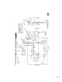
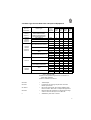
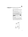
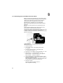
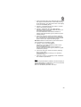
Home
Contents
Page:
Part 2: Installation Instructions Cl. 271 to 274
1.
1.1
1.2
1.3
General Information . . . . . . . .
Safety Notes . . . . . . . . . . . . .
Machine Operation without Material
Tables . . . . . . . . . . . . . . . . .
.
.
.
.
2
2
2
2
2.
Assembling the Frame . . . . . . . . . . . . . . . . . . . . . . . . . . .
2
3.
Completing and Screwing On the Table . . . . . . . . . . . . . . . . .
5
4.
4.1
4.2
4.3
4.4
Connecting the Sewing Drive to the Table . . . . . .
General Notes . . . . . . . . . . . . . . . . . . . . . . .
Motor Type for each Sub-class and Optional Equipment
Drive Mounting . . . . . . . . . . . . . . . . . . . . . . .
Number of Stitches for 3-phase Drives dependent on the
Belt Pulley Diameter . . . . . . . . . . . . . . . . . . . .
Setting the Motor Protection Switch . . . . . . . . . . .
.
.
.
.
6
6
7
8
. . . .
. . . .
8
9
Inserting the Machine Head, V-belt Placement, Attaching the
Belt Guard, Handwheel and Pedal . . . . . . . . . . . . . . . . . . . .
9
Establishing Plug Connections to the Motor Control and
Attaching the Synchronizer . . . . . . . . . . . . . . . . . . . . . . . .
11
7.
Connecting the Compressed Air Maintenance Unit . . . . . . . . . .
12
8.
Making the Machine Operational and Conducting a Sewing Test . .
13
9.
9.2
9.3
Notes prior to Commissioning a Sewing Drive with Digital
Control Technology . . . . . . . . . . . . . . . . . . . . . . . .
Mains Connection and Direction of Rotation of a Direct Current
Sewing Drive . . . . . . . . . . . . . . . . . . . . . . . . . . . .
Correction of the Set Values (Parameters) . . . . . . . . . . . .
Light Barrier Function with Quick . . . . . . . . . . . . . . . . .
10.
4.5
5.
6.
.
.
.
.
.
.
.
.
.
.
.
.
.
.
.
.
.
.
.
.
.
.
.
.
.
.
.
.
.
.
.
.
.
.
.
.
.
.
.
.
.
.
.
.
.
.
.
.
.
.
.
.
.
.
.
.
.
.
.
.
.
.
.
.
. . . . .
. . . . .
. . . . .
. . . . .
Median
. . . . .
. . . . .
.
.
.
.
.
.
.
.
.
.
.
.
.
.
.
.
.
.
.
.
.
.
.
.
. . . . .
14
. . . . .
. . . . .
. . . . .
14
15
16
Keys on the Arm Head . . . . . . . . . . . . . . . . . . . . . . . . . . .
17
11. Setting the Synchronizer . . . . . . . . . . . . . . . . . . . . . . . . . .
11.1 Positioning Drive without External Control Panel . . . . . . . . . . . . .
11.2 Positioning Drive With External Control Panel . . . . . . . . . . . . . . .
19
19
20
9.1
12.
13.
Lifting and Lowering Functions of the Carrier Roller by
Classes 273 and 274 . . . . . . . . . . . . . . . . . . . . . . . . . . . .
24
On and Off Switching Functions of the Edge Cutter by
Classes 272-640142 and -740142 . . . . . . . . . . . . . . . . . . . . .
25
1. General Information
1.1 Safety Notes
For Special Attention!
The mains voltage and the operating voltage shown on
the motor rating plate must be in agreement.
All work on electrical components is only to be conducted
by authorized personnel and with the mains plug
disconnected.
The safety instructions are to be observed.
Installation is to proceed according to the following
instructions.
–
The electrical connections are to be found in the
circuit diagram.
–
The sub-class specific arrangement of inputs and
outputs, as well as the appropriate parameter no.s
are listed on the data sheet.
–
All required parts are included in the accessories
package.
1.2 Machine Operation without Material
In this case the pressure feet must first be locked in the
raised position.
1.3 Tables
The cutouts in tables made in-house must have the
dimensions shown in the sketches.
The tables must also have the necessary load capacity
and stability.
2. Assembling the Frame
Assemble the frame parts as shown in the illustration.
Slide on the enclosed frame feet 1.
A stable positioning of the frame can be achieved after
loosening the screws 2.
The desired work height and a horizontal working plane
can be set after loosening screws 3.
3
2
1
2
3
Schnitt - Selection
B-B
* auf Wunsch
* on request
unbemaßte Radien R9
undimension radius R9
Ankörnung für Befestigung
des Gestells auf Tischplattenunterseite
Ref. mark for fastening the
stand on the reserve of the
table
Schnitt - Selection
A-A
Oberseite
Top side
Schnitt / Section
C-C
Einzelheit / Detail
X
791 1012
Einzelheit / Detail
Y
1
791 1011
ab/from
10/93
Auflagepunkt /
Supporting point
bis/till
9.93
3
2
4
5
8
7
4
6
3. Completing and Screwing on the Table
–
Screw on the reinforcement brace 2 between the
cutouts for the machine head and the motor belt.
–
Screw the cable channel 5 and the mounting for the
wiring tension relief to the underside of the table.
–
–
–
–
–
Screw on the main switch 6.
Screw on the sewing light transformer, if included.
Lay the electrical wiring.
Screw on the drawer 8 with its mounting.
Screw the table onto the frame with B8x35 wood
screws. The positioning of the table to the frame can
be seen in the reference mark on the underside of
the table. See the dimension sketch.
–
Press the bottom hinge parts 3 for the machine
hinges into the recesses in the table and screw fast.
–
For the forward rest of the machine head insert two
rest plugs into the table and slide on pressure
springs. The left plug 1 must be inserted into the
hole as per section C-C and the right plug into the
hole as per detail Y. The ends of the plugs protruding
on the bottom of the table are to be cut off.
Technical Feature!
Through the positioning of the left retainer plug 1 a
lifting of the left machine hinge by ca. 1mm results
and thus an uncoupling from the table.
–
Screw the oil baffle 7 under the table with wood
screws in such a way that there is a gap of 55 mm
between the right edge of the oil baffle and the right
edge of the table cutout. Align the oil baffle to the
front and rear edge of the table cutout in such a way
that the machine head does not hit when tilted over.
The knee lever should later not hit the oil baffle in
any of its possible settings.
5
4. Connecting the Sewing Drive to the Table
4.1 General Notes
Complete drive packages for the 271, 272, 273 and 274
consisting of the sewing drive, the main switch with
wiring, the V-belt pulleys, the V-belt and diverse parts are
available.
The 3-phase clutch motors are normally laid out for
3x380-400V 50 Hz. The number of revolutions is 2800
rpm. -phase motors for other mains voltages are available
on request.
Direct current drives for these machines are operated
with a "single phase alternating current". Therefore, with
multiple machines the connections must equally
distributed to the individual phases of the 3-phase mains
circuit. Otherwise this can cause overloading of individual
phases.
The motor type required for each sub-class and various
optional equipment can be seen in the table following in
Section 4.2.
Attention!
When sewing drives for the 273 and 274 are attached it
should be checking during subsequent commissioning if
the correct functions for the carrier roller have been
entered into the motor controls. See Section 12.
If the electrical equipment was not supplied by DÜRKOPP
ADLER testing should be conducted to EN 60204-3-1 or
JEC 204-3-1.
6
4.2 Motor Type for each Sub-class and Optional Equipment
271 272
273 274
Sub-class
-140041
-640141
-140042
-160062
-240042
-640142
Motor Type
Control
Panel
( )on
request
Optional Equipment
Z120
1801
Z133
371
Z116
6741
Z124
401
FIR 1100F-ZT37
Efka VD552/6F62AV
Efka DC1600/DA62AV
Quick QD552/D21K01
FIR 1180F70
Efka VD552/6F62AV
-
x
-
-
-
670
V62
x
x
-
-
-
Efka DC1600/DA62AV
(V62)
x
-
-
-
V720
x
x
V730
x
x
x
DB4
x
Quick QD552/D40K021)
DB5
x
x
V720
x
x
Efka DC1600/DA82CV1)2)
3201
V730
x
x
x
DB4
x
x
Quick QE6040/D40S021)2)
DB5
x
x
x
V720
x
o
Efka VD552/6F72CV2049
V730
x
x
o
V720
x
o
Efka DC1600/DA82CV3201
V730
x
x
o
DB4
x
o
Quick QE6040/D40S02
DB5
x
x
o
V720
x
x3)
Efka DC1600/DA82AV2)
3207
V730
x
x
x3)
DB4
x
x3)
Quick QE6040/D50S012)
DB5
x
x
x3)
1) For the classes 273 und 274 only the drives marked
with 1) may be used.
2) Direct current-positioning drives for connection to
1x220-240V 50/60Hz
3) Not for classes 273 und 274
Efka VD552/6F72CV20491)
-140042
-160062
-240042
-640142
-740142
-140042
-160062
Z133371
–
–
Z1166741
–
Device for sewing with two preset needle thread
tension values. See under 1.3 Optional equipment.
Z124401
–
Electropneumatic operation for switching the edge
cutter on and off via keys for 272-640142.
o
–
Standard by sub-class -740142.
Z120181
Thread wiper
Light barrier for sewing stop at seam end with
follow-up functions
7
4.3 Drive Mounting
–
Fasten the drive with its foot to the underside of the
table. Hereto screw the 3 hexagon head screws,
M8x35, into the nuts 4 (see table dimension sketch).
–
With the ground cable 2 found in the drive package
make a connection between the motor foot and the
underside of the machine.
–
Here fasten the cable eye with a M4 screw to the
threaded hole in the motor foot.
–
Lead the cable through the oil baffle and attach the
flat plug 1 to the connector strip as shown in the
illustration.
–
The ground cable serves to conduct the static charge
on the machine head to ground via the motor.
–
–
Fasten the V-belt pulley to the motor shaft.
Check the arrangement of the connections on the
sewing drive transformer and correct appropriate to
the available mains voltage, if necessary. See
enclosed circuit diagram.
1
2
4.4 Number of Stitches dependent on the Belt Pulley Diameter
Number of Stitches for 3-phase Drives
Stitches/min
50 Hz
60 Hz
3800
4000
4200
4500
4800
5000
5500
80 mm
85 mm
90 mm
95 mm
100 mm
106 mm
112 mm
67
71
75
80
85
90
95
mm
mm
mm
mm
mm
mm
mm
Direct current drives reach much higher rpm than 3-phase drives. Therefore a smaller
belt pulley diameter is to be chosen here.
As a rule of thumb:
Belt pulley diameter for alternating current drives minus 30% gives the suitable
diameter for direct current sewing drives.
The motor revolutions can also be regulated at the control panel.See motor operation
instructions.
8
4.5 Setting the Motor Protection Switch
Motor Type
3 x 380-400V
1,6A
2,5A
1,9A
FIR
Efka VD552/....
Quick
Mains Voltage
3 x 220-230V
2,7A
4,2A
3,3A
3 x 415-440V
2,4A
1,7A
5. Inserting the Machine Head, V-belt Placement, Attaching
the Belt Guard,Handwheel and Pedal
–
–
4 3
Tap in the support 2 which is necessary for tilting
over the machine. (Not by classes 273 and 274.)
–
Insert the timing pin 4 found in the accessories
package into one of the slots in the built-in
adjustment disk. Loosen the handwheel screws and
remove the handwheel.
–
By machines with thread trimmer and automatic tying
stitch break the marked opening 6 out of the belt
guard with the aid of a screw driver.
–
As seen in the illustration at the left, one first pushes
the V-belt through the belt guard from the outside
and guides both parts over the belt pulley to the
machine head.
–
–
–
Place the V-belt on the belt pulley on the handwheel.
2
5
Insert the machine head into the table cutout.
Tighten the four screws 5 on the belt guard.
Then tilt the machine head to the back and place the
V-belt on the motor pulley.
–
When tilting, the belt guard must enter the table
cutout unimpaired.
–
By slewing the motor, tension the V-belt so that it can
be pressed in at the middle by about 10 mm without
great effort.
–
Screw on the motor belt guard and set its cams so
that the belt remains on the V-belt pulley with the
machine tilted to the back.
6
9
Attention!
The holes for fastening the handwheel are arranged
asymetrically.
–
When attaching the handwheel insert the timing pin 4
from the accessories package through the hole 3 into
the deeper slot A of the adjustment disk mounted on
the arm shaft.
–
Set the handwheel with letter A at the mark 7 and
turn the screws 8 tight.
4
7
8
–
Set the connecting rod 9 so that the pedal 10
assumes a position of 10 degrees to horizontal, e.g.,
with its forward edge lower and with its rear edge
slightly raised.
–
For ergonomic reasons the pedal, in its sideways
orientation on the frame brace, should be so
fastened that the pedal middle lies under the needle.
9
10
10
3
6. Establishing Plug Connections to the Motor Control and
Attaching the Synchronizer
–
All electrical connections to the machine head are
made via the central plug connection 16. The wiring
complete with coulpling and plug for the motor
control is in the accessories package.
–
The coupling can be pulled out with the lock tabs 15
pressed in simulatiously.
–
If supplied fasten the external control panel to the
machine arm with the screws 17.
–
Lay the wiring for keys and possibly sewing light in
the cable channel of the machine head. Here the
spooler lid is to be removed.
–
With the main switch off place the synchronizer on
the handwheel flange so that its groove locks over
the mounting pin on the belt guard.
–
By Efka motors with control panel set position D of
the handwheel (needle tip in the needle plate) at the
mark 11 and insert the timing pin.
–
–
–
Precisely align the line mark 12 and the notch 13.
Tighten the screws of the synchronizer.
This is position 0, that is the dependent initial
position for all machine positions set at the factory.
–
With a thus attached synchronizer the lower and
upper needle position set at the factory are the case.
Other Motors
Here the machine positions are to be checked and, if
necessary, set per Section 11 after the attachment of the
synchronizer.
11
12 13
14
15
17
16
11
7. Connecting the Compressed Air Maintenance Unit
–
For the operation of certain sub-classes and optional
equipment a supply of water-free, slightly oiled
compressed air is required.
–
Attach the maintenance unit to the frame as shown
in the illustration.
–
Establish the Pu3 hose connection 1 between the
maintenance unit and machine head.
–
Connect the maintenance unit with customer
supplied connection hose 4 and fittings to the
compressed air -supply mains.
–
With disconnected or shut off compressed air supply
fill the oil reservoir 3 up to the groove marking with
ESSO SP-NK 10 lubricating oil after removing screw
2.
–
After pulling up and turning the grip 5 set the
operating pressure at 6 bar.
5
1
2
4
3
12
8. Making the Machine Operational and Conducting a
Sewing Test
–
–
–
Clean the machine after delivery.
Attach the thread stand as per the following sketch.
As shown, close the thread holes with the enclosed
plugs.
–
Needle and bobbin thread may only be threaded
through one thread hole each.
–
Fill the oil reservoir for hook lubrication and central
oil wick lubrication up to the "Max" mark with oil. See
Section 4 of the operating instructions.
–
It is essential to use ESSO SP-NK 10 or an oil of
absolutely comparable quality for lubrication.
–
Insert the mains plug. By switching on the motor
protection switchs for a short period on 3-phase
sewing drives establish the direction of rotation at
the ventilator wheel of the motor.
–
Machine direction of rotation see arrow on the belt
guard.
–
by incorrect direction of rotation exchange 2 phases
on the mains plug.
–
Allow the machine to run for a few minutes at low
rpm before sewing with the highest allowable rpm.
–
Check the pumping quantity of the oil mister (approx.
1 drop per 15 work cycles ) and correct, if necessary.
See Section 4 of the operating instructions.
13
9. Notes prior to Commissioning a Sewing Drive with
Digital Control Technology
Before commissioning these drives special attention
should be given to the notes listed in the following in
order to protect the drive and sewing machine from
damage.
It is essential that the operating instructions
enclosed with each sewing drive be observed.
9.1 Mains Connection and Direction of Rotation of a Direct Current
Sewing Drive
Switching the drive between mains voltages between
190 V and 240 V (50 and 60 Hz) occurs via internal
switching.
The drive is supplied with a Schuko plug from the factory.
If connection to 3-phase mains is required, the Schuko
plug can be replaced by a Perilex plug. It should be
connected to one of the 3 phases (L1, L2 or L3), the
neutral (N) and the ground lead (or PE).
With 3-phase mains the motors should be connected
equally distributed among the 3 phases.
We recommend marking the Perilex plug so that will show
on the outsidewhich phase is connected. This makes an
overview of the distribution possible.
The drive is normally supplied with the correct machine
direction of rotation, e.g. running to the left
(counter-clockwise).
The direction of rotation can be changed at the following
parameters:
–
Run to the right when looking at the V-belt pulley
(clockwise)
with Efka modular = F161-0
with Quick digital = 800-1
–
Run to the left when looking at the V-belt pulley
(counter-clockwise)
with Efka modular =F161-1
with Quick digital = 800-2
For the necessary access to the service level of the
controls see Section 11.2 or the enclosed motor operating
instructions.
Arrangement of the connections in a Perilex plug. Seen
from the connection side.
14
9.2 Correction of the Set Values (Parameters)
For adaption of the drive to the individual machine class it
is essential that several parameters be checked and, if
necessary, the values set at delivery corrected.
Here the parameter no. of the parameter to be corrected
must be selected and the value shown in the display
increased (+) or reduced(-).
The following parameter no.s are to be given particular
attention:
a) Maximum Rpm
F111 with Efka modular
607 with Quick digital
No greater number of stitches/min. may be set than is
allowed under Section 1.2 of the machine class to be
powered. The set value is the first informtion shown
in the display after the main switch is turned on.
With 3-phase sewing drives the max. number of
stitches/min. (pedal stepped fully down) must be
chosen by selecting the motor belt pulley. See
Section 4.4.
The max. number of stitches/min. shown in the control
panel must be set accordingly to the value of the
motor belt pulley in the above parameter.
A reduction in the number of stitches below max. is then
possible at the control panel.
b) Reference position (0-Position)
F170 with Efka modular
700 with Quick digital
Setting before inserting the 10-pole machine plug into the
motor control is essential. The reference position is
reached when the handwheel is turned in the
direction of operation and arrested in position D.
In this position the needle position slot F and the needle
position slot C are simultaniously correctly set for
most applications. Corrections of these needle
positions are possible in the following parameters:
with Efka modular
F-171. 1- Needle position slot F
F-171. 2- Needle position slot C
with Quick digital
702 - Needle position slot F
703 - Needle position slot C
(See Section 11.)
15
c) 884 - Regulation parameter with Quick
With the value set in parameter 884 the rpm regulation
characteristics are adapted to the individual load of
the machine class to be powered. Heavy machines
require a greater value than light machines.
A too high set value can be heard in an audible "motor
growl" in the lower rpm ranges.
A too low set value shows itself in regulation problems
with higher performance requirements (e.g. thread
trimming).
9.3 Light Barrier Function with Quick
On the printed circuit board of the control panel DB 5
there is a wire switch for changing the light barrier
sensitivity.
On delivery of the control panel this switch is closed, that
is the greatest sensitivity is switched on and thus
prepared for connection to the light reflection barrier
Weko 7245 (Part no.: Z133 103).
Other manufacturer’s light barriers (e.g. Leutze)
sometimes require a reduced sensitivity. In this case the
wire switch must be opened.
In case of problems with the light barrier function we
recommend that this switch also be checked. Here the
front of the control panel must be opened.
16
10. Keys on the Arm Head
–
Machines with automatic tying stitches have four key
pads 1 as standard equipment.
–
Fasten the keys found in the accessories package
with the two screws 2 to the arm head as shown in
the illustration.
–
Remove the spooler lid and lay the wiring in the
cable channel.
–
Guide the plug through hole in the table and insert
into the motor control.
1
2
17
12
7
8
11
9
10
10
3
18
4
11. Setting the Synchronizer
The adjustment disk built into the machine arm has slots
which are marked by letters on the handwheel.
In conjunction with the marking 4 the letters show the
position of the slots in which the machine can be arrested
with the enclosed pin 3.
After the synchronizer, with the main switch turned off,
has been so fastened to the handwheel flange that its
groove positions over the holding pin on the belt guard,
one can quickly check or set the positions.
1st. Position
The machine should stop in the lower needle position =
Slot F.
2nd. Position
The machine should stop in the thread lever up position =
Slot C
11.1 Positioning Drive without Exteral Control Panel
Example:Efka DC 1600 DA 62 AV or 6 F 62 AV
Attention!
When adjusting the synchronizer disks, turn the main
switch off !
First Position
1. Set switch S3 on the motor control to the right.
(Not with 6 F 62 AV).
2. Operate pedal forward and release.
3. Turn the handwheel in the direction of rotation and
arrest pin 3 in slot F.
4. Turn off main switch.
5. Turn disk 7 drehen until control slit 8 lies behind
switch 9.
Second Position
1. Set switch S3 on the motor control to the left.
(Not with 6 F 62 AV)
2. Turn the handwheel further in the direction of rotation
and arrest with pin 3 in slot C.
3. Turn disk 11 until the control slit 12 lies behind
switch 10.
4. Pull out the pin.
With material inserted check the positions. If necessary
repeat the setting procedure.
19
11.2 Positioning Drive with External Control Panel
Before commissioning with Efka only the position 0 and
with Quick only the reference position are to be entered.
These are the base points for all machine positions.
This initial position corresponds to slot D on the
adjustment disk = Needle tip in the needle plate.
When fastening the Efka synchronizer please observe
Section 6.
All machine positionsehave been programmed at the
factory.
Small mechanical adjustments must be made on the
synchronizer. Its hood cannot be removed.
The machine positions are registered by the synchronizer
in steps (increments) and shown in the display. A
complete revolution is divided with Efka into 510 and with
Quick into 480 steps.
a) Efka Modular
To enter the position 0 one proceeds as follows:
1. Hold key P down.
2
Turn on main switch. The display shows code
no. C-0000.
3. To access "Service Level 1" enter Efka code
no. 1907 with the keys 1....0.
4. Press key E. The display shows parameter no. F 100.
5. With the keys 1...0 enter parameter no. 170.
Key E drücken. - Service Routine 1 (Sr1) appears.
Key F drücken. - Position 0 appears.
6. Turn the handwheel one complete revolution in the
machinen direction of rotation and arrest in position D
with the enclosed timing pin.
This is "Position 0", that is, the dependent base point
for all machine positions set at the factory.
7. Press key P twice.
Check the mahine positions F and C.
This completes the setting.
20
8. Attention! It is essential to sew a seam with thread
trimming. It is only after this that an entered setting
has been stored in memory.
Should a correction of the factory settings be necessary,
then positions F and C should be programmed as follows:
Attention! For all settings continue to turn in the
machine direction of rotation.
1. If the main switch has been turned off in the meantime
then start again as described under "Entering the
position 0".
Otherwise press P. The display shows P170.
2. Press key E twice. The display shows Service
Routine 2 (Sr2).
3. Press key F. Position 1 appears.
Turn the handwheel at least 1 revolution and arrest in
position F.
4. Press key E. The display shows position 2.
Arrest the handwheel in position C.
5. Press key P twice to complete the setting.
6. Attention! It is essential to sew a seam with thread
trimming.
It is only after this that an entered setting has been
stored in memory.
If sewing does not occur the setting will be lost when
the main switch is next turned off.
The number of increments shown for position F = 60 and
Position C = 438 2 each.
21
b) Quick Digital
1. With keys G and minus (-) pressed turn on the main
switch.
The display shows * and e.g. 3000. The asterisk
shows the programming mode and 3000 the number
of stitches/min.
2. Keep key G pressed then tap the minus (-) key.
EINGEBEN (Enter) appears in the display.
Release both keys.
3. Tap key G until G7 .... appears in the display.
4. Tap key F. The display shows 7000*XXXX, that is, a
random number, which corresponds to the
screwed-on setting of the synchronizer.
5. Step the pedal forward. - The machine positions as
desired.
6. Turn the handwheel in the machine direction of rotation
and arrest with the timing pin in position D of the
handwheel.
This is the reference position for further machine
positions.
7. Remove timing pin. Commit the reference position to
memory by stepping down on the pedal.
8. Check reference position D with the timing pin again.
With incorrect positioning as can result from the
drawing forward of the motor rotor into the so-called
"Drawn Forward Position" the settings as described in
6. and 7. are to be repeated.
9. Press the G and minus (-) keys simultaniously. The
display shows * MANUAL.
Check the machine positions F and C. This normally
completes the setting.
Should a correction of the factory settings be necessary
programming of the machine positions F and C is to
proceed as described.
Attention! For all settings continue to turn in the machine
direction of rotation.
22
1. If the main switch has in the meantime been turned off
start again as described above. Otherwise press key
G and the minus (-) key at the same time. The display
shows E EINGEBEN (Enter).
2. Tap key F. The display shows 700 *XXXX = number
value of the reference position.
3. Tap key F repeatedly until 702* 0026 appears.
Step down briefly on the pedal. Machine positions in
the position set at the factory.
Turn the handwheel in the machine direction of
rotation and arrest the timing pin in position F (lower
needle position).
4. Pull out the timing pin. Store the value by stepping
down on the pedal. Check position F with the timing
pin. If necessary, e.g. because of the drawn-forward
position of the rotor, repeat the setting again.
Attention! Because of tolerances the set values shown
for the positions can fluctuate by 0002.
5. Tap key F once. 703* 0205 appears.
Step down on the pedal. Machine positions in the
position set at the factory.
Turn the handwheel in the machine direction of
rotation and arrest the timing pin in position C (upper
thread lever position).
6. Pull out the timing pin. Store the value by stepping
down on the pedal.
Check position C with the timing pin. If necessary
repeat the setting.
7. Press keys G and (-). The display shows * MANUELL.
The machine is operational.
Note!
The control panel makes it possible to show the display in
different languages. For this tap key F to 733. Choose the
desired language with the keys - or +.
Return to the desired parameter with key F.
23
12.Lifting and Lowering Functions of the Carrier Roller
with Classes 273 and 274
The carrier roller is automatically raised when the
pressure foot is lifted and with seam back tacking.
The lowering function can occur without delay or after a
set number of stitches.
This is to be entered with the appropriate parameter no.s
at the control panel. For the necessary access to the
service level see Section 11.2
a) Efka Modular or b) Quick Digital.
Motor type
Efka Modular
Quick Digital
Flip-Flop
Mode
Parameter 190
Flip-Flop 5
Parameter 510
Flip-Flop 5
Lowering after
a number
of stitches
Parameter 191
Set number of stitches
(max.254)
Parameter 550
Set number of stitches
(max.254)
Lowering
without delay
Parameter 191
Set number of stitches at 0
Parameter 550
Set number of stitches at 0
24
13. On and Off Switching Functions of the Edge Cutter
by Classes 272 - 640142 and - 740142
In order to conduct the functions described below with the
272 - 640142 it must be equipped with the optional
equipment Z 124401. The optional equipment consists of
the electro-pneumatic operation for the edge cutter.
The various on and off switching ffunctions can be
entered with the appropriate parameter no.s at the control
panel.
For the necessary access to the service level see
Section 11.2 a) Efka Modular or b) Quick Digital.
Motor type
Efka Modular
Quick Digital
Flip-Flop
Mode
Parameter 190
Flip-Flop 6
Parameter 510
Flip-Flop 6
On after
a number
of stitches
Parameter 192
Set number of stitches
(max.254)
Parameter 551
Set number of stitches
(max.254)
Off after
a number
of stitches
Parameter 193
Set number of stitches
(max.254)
Parameter 552
Set number of stitches
(max.254)
On - Off
manually
via keys
Parameter 192 at 0
Parameter 193 at 0
Parameter 194 at Off
Parameter 552 at 0
Parameter 551 at 0
Parameter 504 at 1
Off after
thread trimming
Parameter 194 at On
Parameter 504 at 2
On - Off
Parameter 190
with motor run signal Flip-Flop 3
via pedal
Parameter 510
Flip-Flop 3
25