1
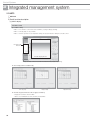
Control Systems
, Individual Control Systems ,, Centralized control systems
1 Wireless signal receiver kit
MRK-A10N
1) Features . . . . . . . . . . . . . . . . . . . . . . 8
2) Wiring. . . . . . . . . . . . . . . . . . . . . . . . 8
2 Wireless remote controller
MR-DH00
1) Features . . . . . . . . . . . . . . . . . . . . . . 8
2) Description of parts . . . . . . . . . . . . . 9
3) Additional function . . . . . . . . . . . . . 10
3 Wired remote controller
1. MWR-WE10N
1) Features . . . . . . . . . . . . . . . . . . . . . 11
2) Product specification . . . . . . . . . . . 11
3) Description of parts . . . . . . . . . . . . 12
4) Optional function . . . . . . . . . . . . . . 14
5) Display . . . . . . . . . . . . . . . . . . . . . . 21
6) Communication diagram . . . . . . . . 23
2
1 Interface module
1. MIM-N00
1) Features . . . . . . . . . . . . . . . . . . . . . 26
2) Product specification . . . . . . . . . . . 26
3) Description of parts . . . . . . . . . . . . 26
4) Wiring. . . . . . . . . . . . . . . . . . . . . . . 27
5) Display . . . . . . . . . . . . . . . . . . . . . . 28
2 On/Off controller
MCM-A202DN
1) Features . . . . . . . . . . . . . . . . . . . . . 29
2) Product specification . . . . . . . . . . . 29
3) Description of parts . . . . . . . . . . . . 30
4) Optional function . . . . . . . . . . . . . . 31
5) Connection diagram . . . . . . . . . . . . 32
6) Display . . . . . . . . . . . . . . . . . . . . . . 35
3 Operation mode selection switch
MCM-C200
1) Features . . . . . . . . . . . . . . . . . . . . . 36
2) Installation . . . . . . . . . . . . . . . . . . . 36
3) Control example . . . . . . . . . . . . . . . 37
systems
1 DMS2
MIM-B14
1) Features . . . . . . . . . . . . . . . . . . . . 102
2) Description of parts . . . . . . . . . . . 102
3) Installation . . . . . . . . . . . . . . . . . . 102
4) Control . . . . . . . . . . . . . . . . . . . . . 103
CENTRALIZED
CONTROL SYSTEM
INTEGRATED
POWER
MANAGEMENT SYSTEM CISTRIBUTION SYSTEM
MIM-D00AN
1) Features . . . . . . . . . . . . . . . . . . . . . 40
2) Product specification . . . . . . . . . . . 40
3) Description of parts . . . . . . . . . . . . 41
4) Connection diagram . . . . . . . . . . . . 43
5) Wiring. . . . . . . . . . . . . . . . . . . . . . . 43
6) Function . . . . . . . . . . . . . . . . . . . . . 46
1 External contact interface module
INDIVIDUAL
CONTROL SYSTEM
,,, Integrated management 9 External contact control system
2 S-NET3
MST-P3P
1) Features . . . . . . . . . . . . . . . . . . . . . 75
2) PC specification . . . . . . . . . . . . . . . 75
3) System connection. . . . . . . . . . . . . 75
4) Function . . . . . . . . . . . . . . . . . . . . . 76
5) Detail function description . . . . . . . 77
EXTERNAL CONTACT
CONTROL SYSTEM
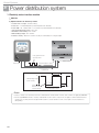
,9 Power distribution system
1 Electricity meter interface module
BUILDING
MANAGEMENT SYSTEM
MIM-B16
1) Features . . . . . . . . . . . . . . . . . . . . . 92
2) Display and buttons . . . . . . . . . . . . 92
3) Connectors . . . . . . . . . . . . . . . . . . 93
4) Address & option switches . . . . . . . 93
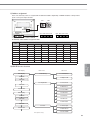
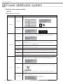
5) Specifications on electricity meter. . . 94
6) Installation . . . . . . . . . . . . . . . . . . . 95
7) Wiring. . . . . . . . . . . . . . . . . . . . . . . 96
8) Address assignment. . . . . . . . . . . . 97
9) MIM-B16 menu structure . . . . . . . . 97
10) Setting parameters on DMS2 (MIM-D00AN ). . 99
11) Error . . . . . . . . . . . . . . . . . . . . . . . 99
3
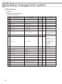
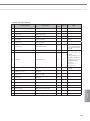
9, Building management systems
1 LonWork Gateway
MIM-B18N
1) Features . . . . . . . . . . . . . . . . . . . . 108
2) Product specification . . . . . . . . . . 108
3) Description of parts . . . . . . . . . . . 109
4) Connection diagram . . . . . . . . . . . 111
5) Wiring. . . . . . . . . . . . . . . . . . . . . . 111
6) Commission . . . . . . . . . . . . . . . . . 114
7) Standard program identifier (SPID) 114
8) Item summary . . . . . . . . . . . . . . . 114
9) Network variable . . . . . . . . . . . . . 115
10) Network parameter chart . . . . . . . . 116
11) Network variable list. . . . . . . . . . . . . . 117
12) Detail description of network variable 117
2 BACnet Gateway
MIM-B17N
1) Features . . . . . . . . . . . . . . . . . . . . 122
2) Product specification . . . . . . . . . . 122
3) Description of parts . . . . . . . . . . . 123
4) Connection diagram . . . . . . . . . . . 125
5) Wiring. . . . . . . . . . . . . . . . . . . . . . 125
6) Description of device ID . . . . . . . . 128
7) Object list . . . . . . . . . . . . . . . . . . . 129
8) Checking BACnet communication
through Wireshark . . . . . . . . . . . . 133
9) Standard object type . . . . . . . . . . . . 136
10) Property support specification . . . . . 137
4
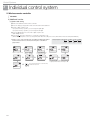
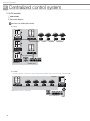
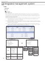
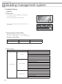
Overview of DVM S
New communication system diargram
BACnet GW
(MIM-B17N)
Lonworks GW
(MIM-B18N)
DMS-Bnet
S-NET3 (MST-P3P)
DMS-Lnet
Ethernet
Lon
ACK
SVC
DMS2
(MIM-D00AN)
Control layer
Max.16 Controllers
(Includes DMS2, PIM)
Set layer
Max.16 outdoor units
Max. 128 indoor units (Includes ERV, MCU)
Max. 80 units
(Max. 64 Indoor units, Max 16 MCU, Max.16 ERV)
Max.16 Controllers
F1F2
R1R2
CH1
On/Off controller (MCM-A202DN)
Indoor units
R1R2
Outdoor units
On/Off controller (MCM-A202DN)
F3F4
Wired RC
(MWR-WE10N)
Local layer
CH2
On/Off controller (MCM-A202DN)
Outdoor units
On/Off controller (MCM-A202DN)
Outdoor units
Max.2 Wired RC
Max.16 indoor units
CH3
CH4
On/Off controller (MCM-A202DN)
Outdoor units
• Set Layer (F1F2)- Communication channel of Outdoor(Main) unit,
Indoor unit and Set layer controller(On/Off controller)
• Control Layer(R1R2) - Communication channel of Outdoor(Main)
unit and Control layer controller(On/Off controller, DMS2)
PIM
Max. 8 PIMs
• Local Layer(F3F4) - Communication between indoor unit and
Wired remote controller
CH5
PIM (MIM-B16)
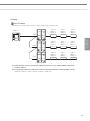
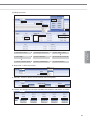
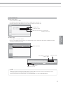
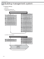
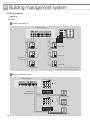
• Case 1 > When DVM S be connected to conventional system
• Case 2 > When DVM+4 be connected to new system
S-NET3 (MST-P3P)
S-NET3 (MST-P3P)
DMS2
(MIM-D00A)
On/Off controller
(MCM-A202D)
MIM-N00
DMS2
(MIM-D00AN)
On/Off controller
(MCM-A202DN)
New interface
module
(After July. 2013)
Interface module
(MIM-B13E)
DVM+4
Conventional
communication system
DVM S
New communication
System
DVM S
New communication
System
DVM+4
Conventional
communication system
5
'90&21752/
6<67(06
6
Individual Control Systems
INDIVIDUAL
CONTROL SYSTEM
,
1 Receiver & Display unit . . . . . . . . . . . . . . . 2 Wireless remote controller . . . . . . . . . . . . 3 Wired remote controller . . . . . . . . . . . . . . 7
Control Systems
,
Individual control system
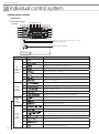
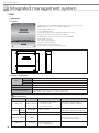
1. Receiver & Display unit
MRK-A10N
1) Features
Receiver wire
(Unit : mm)
Receiver & Display Unit
• Concealed wireless signal receiver
• Filter replacement sign
• Fan operation display
• Operation Timer setting display
• Operation On/Off button
• Operation On display LED (blue)
• Defrost operation display LED (red)
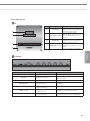
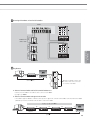
2) Wiring
• Connect one end of the receiver wire with the Receiver & Display unit PCB.
• Connect the other end of the receiver wire with the duct type indoor unit PCB.
Indoor unit PCB
Connector : 13Pin
Receiver & Display unit PCB
; Note
Wire length: 10m
Receiver & Display unit is only available for a duct type indoor unit.
2. Wireless remote controller
MR-DH00
1) Features
(Unit : mm)
• Operation ON/OFF control
• Fan speed control
• Operation temperature setting
• Filter replacement alarm reset
• Air swing control
• Simple On/Off timer
• Indoor unit option code setting
8
Easy and convenient operation control
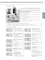
2) Description of parts
⑰
①
⑱
⑨
⑲
⑪
⑫
⑤
⑥ TX
⑥ TY
⑦
⑧
INDIVIDUAL
CONTROL SYSTEM
②
③
⑩
④
⑳
⑭
⑬ TX
⑬ TY
⑮
⑯
Ï ②, ⑥-1, ⑥-2, ⑧, ⑬-2, ⑳,
No
Name
①
On/Off button
②
S-Plasma ion button
③
Turbo button
④
Temp + - button
⑤
Horizontal air swing
button
⑥-1
Beep Off button
⑥-2
Room button
⑦
On timer button
is only supported and available in certain indoor units.
Description
Press this button to turn on/off the indoor unit.
Press this button to turn on/off the S-Plasma ion.
Press this button to cool your room quickly and powerfully.
Press this button to increase/decrease the set temperature by 1°C.
Press this button to activate/deactivate horizontal air flow movement.
Press this button to mute the beep sounds that occurs when pressing the button.
Press the 2nF function button and press this button to control individual indoor unit or all indoor
units at once.
Press the button to set the On Timer on.
⑧
2ndF button
Press this button to select the function printed under the button. (Room, Blade function)
⑨
Mode button
Press this button to select one of the 5 operation modes. (Auto, Cool, Dry, Fan, Heat)
⑩
Quiet button
Press this button to select quiet mode.
⑪
Vertical air swing button
>
Fannnnnn button
Filter Reset button
>
⑫
⑬-1
Press this button to activate/deactivate vertical air flow movement. (Not applicable to Duct type
model)
Press this button to select one of the fan speeds. (Auto, Low, Medium and High.)
Press this button to turn off the filter indicator light.
Press the 2nF function button and press this button to control individual blade unit or all blades
at once.
⑬-2
Blade button
⑭
good'sleep button
Press this button to set the good’sleep mode on.
⑮
Set/Cancel button
Press this button to set or cancel the On/Off Timer and good’sleep mode.
⑯
Off Timer button
⑰
Operation mode indicator
Indicates the operation mode.
⑱
Set temperature & On/Off
set time indicator
Basic – Indicates the set temperature.
Timer setting – Indicates the On/Off set time.
⑲
On/Off timer indicator
⑳
Room & Blade selection
indicator
Transmission indicator
2ndF indicator
Low battery indicator
Press this button to set the Off Timer on.
Indicates the On/Off timer setting.
1) When [Beep off/Room] button is pressed after pressing the 2nF button, “Room” indicator
will be displayed with the selected indoor unit number.
2) When [Filter Reset/Blade] button is pressed after pressing the 2nF button, “Blade” indicator
will be displayed with the selected blade number.
Indicates when wireless signal is received (by pressing any buttons).
Indicates when 2nF button is pressed. You can select the second function (Selecting Room/
Blade)
Indicates the battery life.
Air swing indicator
Indicates when vertical or horizontal air flow movement.
Fan speed indicator
Indicates the fan speed settings.
9
Control Systems
,
Individual control system
2. Wireless remote controller
MR-DH00
3) Additional function
(1) Option code setting
>
❶ Remove the batteries from the remote controller.
❷ Press the Temp [+] and [-] button at the same time and insert the batteries.
❸ Set the 2 digits of option code.
If you press the Fan [ ] button, you can change the right digit.
If you press the Fan [ ] button, you can change the left digit.
❹ Press the [Mode] button to set the next 2 digits of option code.
Input 20 digits in total.
❺ Press the
button more than twice to set the indoor unit option code.
(When indoor unit option code is set, a beep will sound. When the setting is incorrect, all the LED on the indoor unit panel will flicker.)
>
Ú Option code is composed with total of 24 digits including page number.
From the wireless remote controller, enter the option code without
page number.
¨
Fan [ ] – Right digit
Fan [ ] – Left digit
>
§
¨
§
§
Page 0
Page 1
¨
ª
§
If you press the [Mode] button after entering first
10 digits, On timer indicator will change to Off.
ª
¨
10
Press the [Mode] button
to set the next 2 digits.
>
Option code input mode
¨
Setting Ex.) Option code: 012345 – 16789A – 212345 – 36789A
Press the [Power] button more than two times
towards the indoor unit.
Page 2
Page 3
3. Wired remote controller
MWR-WE10N
1) Features
(Unit : mm)
19.5
63.8
(1) Air conditioner / ERV control (ERV cannot be connected to MWR-WE10N until end of 2013)
• AC operation ON/OFF control
• AC operation mode, setting temperature, fan speed, air flow direction setting
• AC individual blade control and occupancy detection
(Function is available when indoor units support any of above functions)
• ERV operation ON/OFF control
• ERV operation mode, fan speed setting
• AC/ERV error monitoring
• Filter cleaning alert and reset alert time
• Individual/group control, indoor unit/ERV interlocking control
• Energy saving control
• Control maximum 16 "Indoor unit + ERV" in group with single wired remote controller
(2) Energy saving operation
• Upper/Lower temperature limit setting
• Automatic operation stop: Automatically stops the operation, when it is not used for certain period of time set by user
(3) Weekly operation schedule setting
• Weekly operating schedule (A/C only, ERV only, A/C+ERV)
• Able to set desired AC operation mode, setting temperature and fan speed to operate based on weekly reservation
• Able to apply schedule exception day for fluid management
(4) User convenience function
• Child lock
• Different button permission levels
(Opertion mode, temperature setting, ON/OFF, fan speed)
• Real-time clock: Displays current time, day (Summer time support)
• Built-in room temperature sensor
• Service mode support
- Indoor unit cycle data monitoring
- Indoor unit option code setting and monitoring
- Indoor unit address and option setting and monitoring
2) Product specification
Power Supply
DC12V
Power Consumption
2W
Operating Temperature range
0°C~40°C
Operating Humidity range
30%RH~90%RH
Communication
2-wire PLC
7 Compatible product
• Indoor unit : Only DVM S Series indoor unit
• ERV : Not support (Until end of 2013)
11
INDIVIDUAL
CONTROL SYSTEM
124.0
120.0
Control Systems
,
Individual control system
3. Wired remote controller
MWR-WE10N
3) Description of parts
④ ⑤⑨⑩⑪ ⑫ ⑬
(1) Display
①
②
⑭
⑮
⑯
③
⑥
⑦
⑰
⑱
⑧
⑳
⑲
LED indicator (Green: Normal / Red: Need to be checked)
Operation On/Off button
Temperature setting button
Classification
Air
conditioner
related
information
Schedule
related
information
Ventilator
(ERV)
related
information
Common
function
related
information
Function
Indication
①
Displays air conditioner operation
②
Displays Quiet/Sleep operation
③
Displays Indoor temperature/Set temperature
④
Displays discharge temperature control
⑤
Displays CO2 /power consumption
⑥
Displays AC fan speed
⑦
Displays Blade selection
⑧
Displays Air swing(Up/Dn)
⑨
Weekly schedule/Holiday setting displays
⑩
Displays Current day( ) or scheduled day(_)
⑪
Displays Schedule number
⑫
Displays Scheduled device selection
⑬
Displays Current time/daylight saving time/scheduled time
⑭
Displays Ventilator(ERV) operation
⑮
Displays Clean up
⑯
Displays Ventilator(ERV) fan speed
⑰
Displays Invalid operation /Filter cleaning (filter cleaning period)
⑱
Displays Dust box cleaning alert/check/part lock / All lock
⑲
Displays Motion detect sensor/Exhaust hood/External interconnection control/Auto
clean/ Humidifying/Energy saving/Outdoor air supply intake/Centralized control
⑳
Displays S-Plasma Ion
Displays Indoor CO2 density
Displays Indoor humidity
Displays remaining time of the auto stop time / ERV delay time
- Solid : Hour unit, Blinking : Minute unit
12
7 ERV cannot be connected to MWR-WE10N until end of 2013
(2) Buttons
⑱
⑬
③
⑳
INDIVIDUAL
CONTROL SYSTEM
⑫
⑨
⑧
②
①
⑮
⑤
⑥
⑦
④⑪ ⑩⑯⑲ ⑭ ⑰
Classification
Air
conditioner
related
button
Common
function
related
button
Function
Button
①
Operation On/Off button
②
Mode button
③
Temperature setting button
④
Fan speed button
Changes the air conditioner’s fan speed
⑤
Air swing button
Changes the air flow direction to move upward or downward
⑥
Temp. button
⑦
Quiet/Sleep button
⑧
Humidity button
⑨
Blade button
Selects a blade for individual control
⑩
MDS button
Set the power to automatically turn off if there is nobody in the room
⑪
Outdoor air intake
Select the AHU Outdoor intake function
⑫
Schedule Button
Select the schedule setting function
⑬
User Set Button
Select the detailed setting function
⑭
Navigational buttons
⑮
Set button
Save new setting
⑯
ESC button
Return to general mode from schedule and detailed setting screens
⑰
Delete button
⑱
Auto Clean button
Use the auto cleaning function for your air conditioner
⑲
CO2/[kWh] button
Display the amount of CO2 and the power consumption
⑳
Filter Reset button
Turn off the filter cleaning displays (filter using time reset)
S-Plasma Ion button
Operation On/Off button
Ventilator
(ERV)
related
buttons
Mode button
Fan speed button
Turn the air conditioner power On/Off
Selects the desired air conditioner operation
Sets the desired temperature
Checks the indoor temperature
Selects quiet or sleep operation for the air conditioner
Turns the AHU humidifying function On/Off
Move between items or change the item value
Cancel the schedule setting
Choose the S-Plasma ion function
Turn the Ventilator(ERV) On/Off
Select the desired operation for the Ventilator(ERV)
Change the fan speed for your Ventilator(ERV)
E. Saver button
Begin Energy Saving Operation
Clean up button
Select air purification through the in/out load controls
7 ERV cannot be connected to MWR-WE10N until end of 2013
13
Control Systems
,
Individual control system
3. Wired remote controller
MWR-WE10N
3) Description of parts
(3) PCB
No.
Name
Description
①
Software upgrade connector
It is used to upgrade the software
②
Communication and power
wiring terminal
Connection with indoor unit (F3/F4)
7 MWR-WE10N uses 2-wire power line communication.
①
②
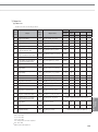
4) Option function
User setting mode
Function
SEG
Used
Default
Range
Unit
Auto stop time setting/checking
1,2
0
0~12 hours
1 hour
Main Sub
menu menu
1
2
Lowest temperature
1,2
16 (61)
16~30°C (61~86°F)
1°C(1°F)
Highest temperature
3,4
30 (86)
18~30°C (65~86°F)
1°C(1°F)
1
0
0 – Unlock, 1 - Lock
-
On/Off button
2
0
0 – Unlock, 1 – Lock
-
Mode button
3
0
0 – Unlock, 1 – Lock
-
Temperature button
4
0
0 – Unlock, 1 – Lock
-
Fan speed button
5
0
0 – Unlock, 1 – Lock
-
Schedule button
6
0
0 – Unlock, 1 – Lock
-
Temp limits [°C(°F)]
All lock
3
Lock of partial button
1
Current Temperature Setting (Year, Month, Date)
2
Current Time Setting (Day, Hour, Minute)
4
1
Summer Time Use and
Setting Methods
1,2/3,4
10/01/01
/5,6
Friday/
Day/
PM
Am,Pm
/1,2/3,4 /12/00
7
14
0
Sun~Sat/AM~PM/0~12/0~59
YY/MM/
DD
Day/
Hour/
Minute
Use of summer time (Y/N)
1
0
0 – No use, 1 – Use
-
Summer Time Application Method
2
0
0 – Weekly, 1 – Daily
-
2
Summer time use (Weekly) Start (? Month, ? th Sunday)
1,2/4
03/F
1~12th month /
1~4,F (last week)th week
-
3
Summer time use (Weekly) End (? Month, ? th Sunday)
1,2/4
10/F
1~12th month /
1~4,F (last week)th week
-
4
Summer time use (Daily) Start (? Month, ? th Sunday)
1,2/3,4
03/22
Jan~Dec /1~31th day
Month, date
5
Summer time use (Daily) End (? Month, ? th Sunday)
1,2/3,4
09/22
Jan~Dec / 1~31th day
Month, date
Backlight Time Setting/Checking
1,2
5
0~30 sec
1sec
Use of LED(Green) (Y/N)
3
1
0 – No use, 1 – use
-
Use of LED (Red) (Y/N)
4
1
0 – No use, 1 – use
-
Ventilator(ERV) Delay
Application (Y/N)
1
0
0 – No use, 1 – use
-
Delay Time
3,4
30
30~60 minutes
1 minute
1
0
0 – No use, 1 – Reset
-
5
6
00~99/1~12/1~31
Ventilator (ERV) delay
time setting/checking
[When using Ventilator
(ERV) interlocking control]
Reset to user mode defaults (except the current time)
7 ERV cannot be connected to MWR-WE10N until end of 2013
f How to set the user mode
(1) If you want to set the detailed settings, press the [User Set] button.
• You will enter the User Set mode, and the [Main Menu] will be displayed.
(2) Refer to the Wired Remote Controller’s User Set list on the next
page to select the desired menu.
• Using the [∧]/[∨] buttons, select a sub-menu number and press the [>] button
to enter the data setting screen.
• Once you have entered the setting screen, the current setting will be displayed.
• Refer to the chart for data setting.
• Using the [∧]/[∨] buttons, change the settings and press the [>] button to
move to the next setting.
• Press the Set button to save the setting and exit to the sub-menu setting screen.
• Press the Esc button to exit to general mode.
; Note
While setting the data, you can use the [∧]/[∨] buttons to set the range of SEG used.
While configuring the setting, press the [Esc] button to exit to the sub-menu setting screen without saving the setting.
f Current time setting (Example)
(1) Press the [User Set] button.
• (Main Menu) will be displayed, and
you can press the [∧]/[∨] buttons to
select No.4, which will set the current
time.
(2) Press the [>] button to select
'Year, Month, Date' in the
[Sub-menu].
• Press the [∧]/[∨] buttons to select
No. 1. You can modify the year/month/
date setting.
(3) Press the [>] button to select
the 'Year'.
• Press the [∧]/[∨] buttons to select
the year ('00~'99).
(4) Press the [>] button to select
the 'Month'.
• Press the [∧]/[∨] buttons to select
month(01~12).
(5) Press the [>] button to select
the 'Day'.
• Press the [∧]/[∨] buttons to select
day(01~31).
(6) Press the [Set] button to
complete your setting of
'Year, Month, Day'.
• The setting changes will be applied
and you can exit to the sub-menu.
(7) In the sub-menu, select 'day,
AM/PM, hour, minute'.
• Press the [∧]/[∨] buttons to select no.
2. You can set the 'day, AM/PM, hour,
minute'.
(8) Press the [>] button to select
the 'Day'.
• Press the [∧]/[∨] buttons to select
day (Sun~Sat).
(9) Press the [>] button to select
'AM or PM'.
• Press the [∧]/[∨] buttons to toggle
between AM and PM.
(10) Press the [>] button to select
the 'Hour'.
• Press the [∧]/[∨] buttons to select
the hour (01~12).
(11) Press the [>] button to select
the 'Minute'.
• Press the [∧]/[∨] buttons to select
minute (00~59).
(12) Press the [Set] button to
complete the current time setting.
• The setting changes are applied and
you can exit to general mode.
(13) Press the [Esc] button to exit to
general mode.
15
INDIVIDUAL
CONTROL SYSTEM
• Using the [∧]/[∨] buttons, select a main menu number and press the [>] button
to enter the sub-menu setting screen.
Control Systems
,
Individual control system
3. Wired remote controller
MWR-WE10N
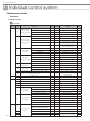
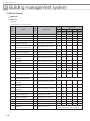
4) Option function
Service mode
Main
menu
Sub
menu
1
2
1
3
4
5
6
2
3
Wireless remote
controller Option
setting / checking
(1)
Wireless remote
controller Option
setting / checking
(2)
Blade setting /
checking
ERV option
Setting / checking
Room temperature
compensation
number of connected
indoor units
Range
Unit
Cooling / Heating selection
1
0
0-Cooling/Heating, 1-Cooling only
-
Use of wireless remote controller
2
1
0-No use, 1-Use
-
MAIN / SUB wired remote controller
3
0
0-MAIN, 1-SUB
-
Temperature unit
4
0
0 – Celsius(°C), 1 – Fahrenheit(°F)
Temperature sensor selection
1
0
0–Indoor unit, 1–Wired remote controller
-
Use of average temperature
2
0
0-No use, 1-Use
-
Use of Auto mode
3
1
-
Temperature display
4
0
0-No use, 1-Use
0–Set temperature,1-Room temperature
AC On/Off button function
5
0
Lock blade 1
1
0
0–Indoor unit+ERV, 1–Indoor
unit only, 2–ERV only
0- Unlock, 1- Lock
Lock blade 2
2
0
0- Unlock, 1- Lock
-
Lock blade 3
3
0
0- Unlock, 1- Lock
-
Lock blade 4
4
0
0- Unlock, 1- Lock
-
Use of By-pass mode
1
0
0-No use, 1-Use
Use of Auto mode
2
0
0-No use, 1-Use
Use of air purification mode
3
0
0-No use, 1-Use
Use of external control
4
0
0-No use, 1-Use
Current room temperature
1, 2, 3
-
-9 ~ 40(°C)
0.1(°C)
Temperature compensation value
4,5,6
-
-9.9 ~ 9.9(°C)
0.1(°C)
Number of indoor units
1,2
0
0~16
-
Number of ERVs
3,4
0
0~16
-
7
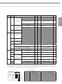
Temperature increment/decrement unit (°C only)
1
-
-
0
Factory option setting
1
-
1
Software code
1~6
-
0-1°C, 1-0.5°C, 2-0.1°C
0-Unchanged,
1-Factory setting
Software code
2
Software version
1~6
-
Software version
-
1
Indoor unit room temperature
1,2,3
-
Room temperature
°C
2
Indoor unit EVA IN temperature
1,2,3
-
EVA IN temperature
°C
3
Indoor unit EVA OUT temperature
1,2,3
-
EVA OUT temperature
°C
4
Indoor unit EEV step
1,2,3
-
EEV step
-
5
6
Indoor unit option
checking(1)
Indoor unit option
checking(2)
1
4
16
SEG
Default
Used
Function
2
3
4
Indoor unit option
setting 2)*
-
Use of central control
1
-
0-No use, 1-Use
-
Use of drain pump
2
-
0-No use, 1-Use
-
Use of electric heater
3
-
0-No use, 1-Use
-
Use of hot water coil
4
-
0-No use, 1-Use
-
Use of external control
1
-
0-No use, 1-Use
-
Use RPM compensation
2
-
0-No use, 1-Use
-
Filter time
3
-
0-2000 hours, 1-1000 hours
Heating temperature compensation
4
-
0-2°C, 1-5°C
-
EEV stop step in heating
5
-
0-0/80 step, 1- 80 step
-
Indoor unit main address
Indoor unit setup address
(Manual setting main address)
Indoor unit RMC address
1, 2
-
Main address (00H~4FH)
-
3, 4
-
Main address (00H~4FH)
-
5, 6
-
Main address (00H~FEH)
-
Indoor unit BASIC option code
Indoor unit INSTALL option
Indoor unit INSTALL option(2)
1)*
1)*
1)*
-
Indoor unit option code
Refer to the indoor unit
installation manual for details
-
Main
menu
Sub
menu
5
2
3
1
2
6
3
4
5
1
2
7
3
4
AHU setting/
checking
Indoor unit, AHU
discharge
temperature
setting /checking
Fresh Duct discharge
temperature checking
ERV Plus setting /
checking
ERV Plus temperature
setting /checking
Master setting/
checking
(F3F4 line Indoor
unit master)
Mode master
indoor unit setting/
checking
(F1F2 line Indoor
unit master) 3)*
1
0
2
3
1)*
2)*
3)*
4)*
Reset
Unit
Setting/checking the different value
1, 2
-
0~30
1
RPM setting /checking
3, 4
-
0~25
1RPM
Filter performance
5
-
0- Pre,
1-Medium performance,
2-High performance
-
Humidity setting / checking
Use of discharge temperature
control
Cooling discharge temperature
6
-
0-30, 1-40, 2-50
-
1
-
0-No use, 1-Use
-
3, 4
-
8~18°C
1°C
Heating discharge temperature
5, 6
-
30~43°C
1°C
Cooling discharge temperature
1, 2
-
13~25°C
1°C
Heating discharge temperature
3, 4
-
18~30°C
1°C
Use of cold air prevention
1
-
0-No use, 1-Use
-
Use of humidification
2
-
0-No use, 1-Use
-
Use of fan operation in defrost
3
-
0-No use, 1-Use
-
Use of humidification
4
-
0-No use, 1-Use
-
Cooling
1, 2
-
15~30°C
1°C
Heating
3, 4
-
15~30°C
1°C
1, 2
-
15~30°C
1°C
3, 4
-
5~15°C
1°C
1, 2
-
0~10°C
1°C
3, 4
-
0-Non use humidifier(0°C)
1-Use humidifier(10°C)
-
1, 2
-
10~27RPM
1 RPM
-
Address
-
-
Address
-
-
Address
-
ERV Plus Auto mode
Set temperature
temperature
Set temperature difference
setting /checking
Setting/checking the compensation temperature A
under the Heating EEV control for ERV Plus
Checking the compensation temperature B under the
Heating EEV control for ERV Plus
ERV
Range
Air supply RPM
Indoor unit master setting/
checking
ERV unit master setting/
checking
Mode master indoor unit
checking
1, 2,3,
4,5,6
1, 2,3,
4,5,6
1, 2,3,
4,5,6
Mode master indoor unit setting
1
-
0-No use, 1-Use, 2-Release
-
Factory setting
1
0
0-No use, 1-Reset
-
1
0
0-No use, 1-Reset
-
1
0
0-No use, 1-Reset
-
Power master reset
4)*
Addressing reset
INDIVIDUAL
CONTROL SYSTEM
1
SEG
Default
Used
Function
SEG1 means option setting page/ SEG2~6 means option code.
If you enter Main menu #4, you must select the targeted indoor unit address and then select the sub menu.
Master indoor unit : The indoor unit which can decide the operation mode. Other indoor unit follows Master indoor unit's operation mode.
Power master reset : Setting for finding the most stable power supply indoor unit.
f To set 24 digit option
Page
Option Setting
How to move between pages
Page1
1~5th digit option
Press the [>] button to go to Page2.
Page2
6~10th digit option
Press the [>] button to go to Page3.
Page3
11~15th digit option
Press the [>] button to go to Page4.
Page4
16~20th digit option
Press the [>] button to go to Page5.
Page5
21~24th digit option
-
17
Control Systems
,
Individual control system
3. Wired remote controller
MWR-WE10N
4) Option function
Service mode
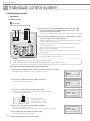
f How to set the service mode
(1) If you want to use the various additional functions for your Wired
Remote Controller, press the [Set] and [Esc] buttons at the same
time for more than three seconds.
• You will enter the additional function settings, and the [main menu] will be displayed.
(2) Refer to the list of additional functions for your Wired Remote Controller
on the next page, and select the desired menu.
• Using the [∧]/[∨] buttons, select a main menu number and press the [>] button
to enter the sub-menu setting screen.
• Using the [∧]/[∨] buttons, select a sub-menu number and press the [>] button
to enter data setting screen.
• When you enter the setting stage, the current setting will be displayed.
• Refer to the chart for data settings.
• Using the [∧]/[∨] buttons, select the settings. Press the [>] button to move to
the next setting.
• Press the [Set] button to save the settings and exit to the sub-menu setting screen.
• Press the [Esc] button to exit to normal mode.
; Note
While setting the data, you can use the [∧]/[∨] buttons to set the range of SEG
While configuring the setting, press the [Esc] button to exit to the setting sub-menu without saving your changes.
f Example method of setting wired remote controller option
(1) Press the [Set] and [ESC] buttons at the same time for more than 3 seconds.
• When(Main menu) is displayed press the [∧]/[∨] button to select no.1.
(2) Press the [>] button to select the number you will set.
• Press the [∧]/[∨] button and select no.1
(3) Press the [>] button to enter the data setting stage.
• When you enter the setting stage, the current setting value will be displayed.
f Example of data setting stage display
SEG1: Heat pump indoor unit
SEG2: Use wireless remote controller
SEG3: Master wired remote controller
SEG4: Temperature display – Celsius (°C)
(4) Press the [<]/[>] button to select the desired Data1.
• Press the [∧]/[∨] button to select no.1.
• The wired remote controller option is set from both cooling and heating to cooling only.
(5) Press [Set] button to complete the option setting.
• Save the setting value and exit to sub menu.
18
(6) Press [Esc] button to exit to normal mode.
Built-in temperature sensor of wired remote controller
f Temperature control with built-in temperature sensor
INDIVIDUAL
CONTROL SYSTEM
Applies to all the indoor units connected within a group.
(However, indoor unit is limited to DVM S series )
Ï Check the setting of the wired remote controller built-in sensor from the service menu.
Main
menu
Sub
menu
1
Function
Cooling / Heating selection
Use of wireless remote
controller
MAIN / SUB wired remote
controller
Temperature unit
Temperature sensor selection
Use of average temperature
Use of Auto mode
Temperature display
Wireless remote
controller Option
setting /
checking (1)
1
2
Wireless remote
controller Option
setting /
checking (2)
AC On/Off button function
Used Factory
SEG setting
1
0
Description
Unit
0-Cooling/Heating, 1-Cooling only
-
2
1
0-No use, 1-Use
-
3
0
0-MAIN, 1-SUB
-
4
1
2
3
4
0
0
0
1
0
5
0
0 – Celsius(°C), 1 – Fahrenheit(°F)
0–Indoor unit, 1–Wired remote controller
0-No use, 1-Use
0-No use, 1-Use
0–Set temperature,1-Room temperature
0–Indoor unit+ERV, 1–Indoor unit
only, 2–ERV only
-
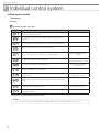
f Heating mode temperature compensation
Indoor unit INSTALL option setting (Refer to indoor unit intallation manual)
SEG
Function
Value
21
Heating setting temperature
compensation
1 – 2°C
2 - 5°C
; Note
When built-in sensor of the wired remote controller is used, heating mode temperature compensation (+2°C or +5°C) will be reset to 0°C.
Ï If there is no option switch on the indoor unit PCB, check the setting of the heating temperature compensation from the service menu.
Main
menu
3
Sub
menu
6
Used Factory
SEG setting
Function
Indoor unit
option
checking(2)
Description
Unit
0-No use, 1-Use
-
Use of external control
1
-
Use RPM compensation
2
-
0-No use, 1-Use
-
Filter time
3
-
0-2000 hours, 1-1000 hours
-
Heating temperature
compensation
4
-
0-2°C, 1-5°C
-
EEV stop step in heating
5
-
0-0/80 step,1-80 step
-
19
Control Systems
,
Individual control system
3. Wired remote controller
MWR-WE10N
4) Option function
Built-in temperature sensor of wired remote controller
f When communication error or power failure occurs while using built-in temperature sensor
(1) When communication error occurs over 3 minutes,
• Indoor unit ignores the built-in temperature sensor and use indoor unit temperature sensor.
• Ignores the temperature compensation setting on the wired remote controller and use the compensation value set on indoor
unit instead.
(2) When communication resumes,
• Built-in temperature use is recovered.
• Setting must be done again to use the temperature compensation.
Energy saving operation mode
N(ERV) : N(Indoor unit)
Ï Energy saving operation mode is available only when there is at least one indoor unit and ERV is connected.
• By comparing indoor room temperature, setting temperature and outdoor temperature, wired remote controller changes
ERV operation mode and fan speed to minimize unnecessary outdoor unit operation.
• Energy saving operation is not available when ERV is not connected.
• Energy saving operation is not available when ‘Centralized control’ is set.
• Energy saving operation will not be executed when ERV is set to Outing mode or set in external interlocking mode.
• Temperature measurement is set as indoor unit temperature sensor as default, and it can be changed depending on the wired
remote controller option setting.
7 ERV cannot be connected to MWR-WE10N until end of 2013
20
5) Display
Erro display
Error codes for the Wired Remote Controller and the product connected to the Wired Remote Controller will be
displayed in the LCD display.
INDIVIDUAL
CONTROL SYSTEM
LCD Display
f When an Error Occurs in Your Indoor/Outdoor Units (Product Group Display : A)
• The product address for the error will be displayed, followed by the error code.
Example : Error 101 occurs for Indoor Unit No. 200012.
Indoor unit
f When an Error Occurs in Your Ventilator(ERV) (Product Group Display : B)
• The product address for the error will be displayed, followed by the error code.
Example : Error 121 has occurred at ventilator(ERV) No. 300012.
Ventilator (ERV)
f When an Error Occurs in Your Wired Remote Controller
• Only an error code will be displayed. (No address will be displayed.)
Example : Error 601 has occurred at your Wired Remote Controller.
21
Control Systems
,
Individual control system
3. Wired remote controller
MWR-WE10N
5) Display
Wired remote controller error codes
Display
Description
Remarks
Communication error between wired remote controller and indoor/ERV units
after successful communication
No communication between Master (Main) and Slave(Sub) wired remote
controllers
No communication between wired remote controller and indoor/ERV units
Wired remote controller is connected on F1/F2 channel
Two or more wired remote controllers are set as Master (Main)
No ERV unit installed for interlocking function
No indoor unit installed for interlocking function
When using Master remote
controller
Detection available from both
Master/Slave wired remote controller
When external interlocking
control is in use
Over 16 indoor/ERV indoor units installed
Indoor units of different temperature setting (°C/°F) connected to same wired
remote controller
Detection available in Master
wired remote controller
Wired remote controller(s) has different temperature unit setting with indoor
unit(s)
Temperature sensor Open/Short error
Detection available in models
with temperature sensor
• Memory error
• No damper feedback
7 ERV cannot be connected to MWR-WE10N until end of 2013
; Note
For the error codes for your indoor/outdoor units and ventilator (ERV), refer to the installation manual of each device.
22
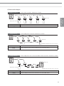
6) Communication diagram
Individual control (1)
Control 1 indoor unit with 1 wired remote controller
F1/F2
INDIVIDUAL
CONTROL SYSTEM
Indoor unit
Outdoor unit
F3/F4
Wired remote controller
Control
All connected indoor units
Display
Operation status of the connected indoor unit
Group control (1)
Control multiple indoor units with 1 wired remote controller
Indoor unit
Outdoor unit
Wired remote controller
Ú Maximum 16 indoor units can be connected
Control
All connected indoor units
Display
Priority 1. Display the status of master indoor unit
Priority 2. Display the status of indoor unit which has the earliest Main address
Group control (3)
Control multiple indoor units connected to different outdoor units with 1 wired remote controller
F1/F2
Outdoor unit
Outdoor unit
F3/F4
Wired remote controller
Ú Maximum 16 indoor units can be connected
Control
All connected indoor units
Display
Priority 1. Display the status of master indoor unit
Priority 2. Display the status of indoor unit which has the earliest Main address
23
Control Systems
,
Individual control system
3. Wired remote controller
MWR-WE10N
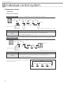
6) Communication diagram
Group control (5)
Control 1 or multiple indoor units with 2 wired remote controllers
F1/F2
Indoor unit
Outdoor unit
F3/F4
Wired remote controller
Master Slave
Master
Slave
Ú Maximum 16 indoor units can be connected
Control
All connected indoor units
Display
Priority 1. Display the status of master indoor unit
Priority 2. Display the status of indoor unit which has the earliest Main address
Ï
Two wired remote controllers identically display the operation status of the indoor unit
according to above priority.
Group control (6)
Control multiple indoor units connected to different outdoor units with 2 wired remote controller
F1/F2
Indoor unit
Outdoor unit
Outdoor unit
F3/F4
Wired remote controller
Master Slave
Ú Maximum 16 indoor units can be connected
Control
All connected indoor units
Display
Priority 1. Display the status of master indoor unit
Priority 2. Display the status of indoor unit which has the earliest Main address
Ï
Two wired remote controllers identically display the operation status of the indoor unit
according to above priority.
Max. distance between the farthest indoor unit and wired
remote controller : 100m
100m
Wired remote controller
24
,,
Centralized control systems
1 Interface module. . . . . . . . . . . . . . . . . . . . 2 On/Off controller . . . . . . . . . . . . . . . . . . . . CENTRALIZED
CONTROL SYSTEM
3 Operation mode selection switch. . . . . . . 25
Control Systems
,,
Centralized control system
1. Interface module
MIM-N00
1) Features
(Unit : mm)
59.4
Interface module that supports
DVM S series outdoor unit
• Communication transmitter between DVM S
series outdoor unit and conventional
communication upper level controllers as below.
(1) On/Off controller : MCM-A202D, MCM-A202B,
96.1
(2) DMS2 : MIM-D00A
(3) BACnet Gateway : MIM-B17
(4) Lonworks Gateway : MM-B18
• 1 interface module for 1 outdoor unit
• Individual control – Max.64 indoor units
• Group control – 16 groups
2) Product specification
Power Supply
DC12V
Power Consumption
2.4 W
Operating Temperature range
-10°C~50°C
Operating Humidity range
10%RH~90%RH
Communication
RS485 x 2
Max.Communication Length
1000M
Maximum number of connection
F1/F2 – 1 outdoor unit
R1/R2 – 1 upper level controller
7 Compatibiliy : Only DVM S series outdoor unit can be connected.
Compatible Models
Outdoor unit
DVM S series only
Upper level controller
①
②
③
④
On/Off controller : MCM-A202D
DMS2 : MIM-D00A
BACnet Gateway : MIM-B17
Lonworks Gateway : MM-B18
3) Description of parts
①
②
⑦
Name
①
F1/F2 communication
connector
Communication connector that connects
to outdoor unit / F1/F2
②
Power connector
DC 12V
③
Communication LED
Check communication with upper level
controllers (Left : No function
Center : Blinks while communicating with
upper level controller
Right : Blinks while communicating with
outdoor unit and indoor unit.)
④
Address setting switch
Sets the address of interface module
⑤
Software update
connector
Using this connector, Interface module
software can be updated
⑥
7-segment
Displays the communication status
between interface module and outdoor
unit/ERV
⑦
Upper level controller
communication channel
Communication connection channel to
upper level controller R1/R2
⑧
DIP switch
See left table
⑧
④
SW1 SW2 SW3 SW4
Off
Off
Off
Off
On
Off
Off
Off
26
No.
⑤
③
⑥
Description
Outdoor unit (New
communication) ¥ Upper
controller (Conventional
communication)
Outdoor unit (Conventional
communication)¥ Upper controller
(New communication)
* Not available function until
July.2013
Description
4) Wiring
Connecting with On/Off controller
MCM-A202D
CENTRALIZED
CONTROL SYSTEM
f 1 On/Off controller connection is supported
• Connect to R1/R2 : 16 groups can be controlled with On/Off controller.
; Note
When DVM S series outdoor unit connect to On/Off controller (MCM-A202DN), do not need to connect MIM-N00.
Connecting DMS2
MIM-D00A
f 1 DMS2 connection is supported
• Connect to R1/R2 : All the indoor units will be controlled.
; Note
When DVM S series outdoor unit connect to DMS2 (MIM-D00AN), do not need to connect MIM-N00.
27
Control Systems
,,
Centralized control system
1. Interface module
MIM-N00
5) Display
Operation display
Display software version
after power input
Before detecting
Outdoor unit
Outdoor unit detection After tracking completed,
during tracking
displays indoor unit address
Error display
f Communication error between outdoor unit and interface module
f Communication error between On/Off controller and interface module after tracking has been completed
Ú When E1 and E2 error occurs simultaneously, only E1 will be displayed.
f Interface module tracking failure
• IDU quantity recognized by outdoor unit ≠ IDU quantity recognized by I/M.
f Indoor unit communication checking
a. No indoor unit response.
(During the normal communication mode after tracking process. Outdoor unit and interface module
communicate normally)
b. When all indoor units are set as "Centralized control disable status".
28
2. On/Off controller
MCM-A202DN
1) Features
CENTRALIZED
CONTROL SYSTEM
• Maximum 16-group controller (Max. 128 units)
• Whole/Group/Individual indoor unit control (On/Off)
• Restriction on the use of wireless/wired remote controllers and
external contact control
• Cooling and heating mode control
• Indoor unit error display
(Unit : mm)
2) Product specification
Power supply
AC200V~240V, 50/60Hz
Power consumption
66W
Operating Temperature range
0°C~40°C
Operating Humidity range
30%RH~90%RH
Communication
RS485 x 1 (R1/R2)
Max. Communication length
1000m
Outdoor unit
DVM S Series outdoor unit only
Controller
On/off controller (MCM-A202DN)
DMS2 (MIM-D00AN)
Set layer
Device : 80 (Max.64 Indoor units, Max.16 ERVs, Max.16 MCUs)
Outdoor unit : 1
On/Off controller : 16
Control layer
Outdoor unit : 16
On/Off Controller : 16 (In case of DMS2 connection, 15)
DMS2 : 1
Control layer can control 128 units. (Indoor unit, ERV, MCU)
Compatibility
Max.
connectable
device number
7 Interface module MIM-B13D, MIM-B13E, MIM-B04A cannot connect.
7 ERV cannot be connected until end of 2013
29
Control Systems
,,
Centralized control system
2. On/Off controller
MCM-A202DN
3) Description of parts
①
⑥
②
③
⑥
&22/
$872
+($7
④
⑧
⑤
⑦
No.
Name
Description
①
Indoor unit operation LED
②
All ON button
Press All ON button to turn on all the indoor units.
③
All OFF button
Press All OFF button to turn off all the indoor units.
④
Group indoor unit
operation LED
⑤
Indoor unit control button
Press each indoor unit button to control the equivalent unit operation.
⑥
Operation mode selection
switch
Set operation mode selection switch to a certain mode and press indoor unit control
button to control operation mode. Whenever pressing any button on the controller, set
operation mode is delivered to the indoor unit.
⑦
Communication terminal
C1 C2 : No function
R1 R2 : Connect to Outdoor unit, DMS2, On/Off controller
⑧
Power terminal
It lights on when more than one indoor unit operates.
It flickers during indoor unit tracking process after power reset.
It lights on when one indoor unit of the group is operating.
It also flickers when indoor unit has an error.
During tracking indoor units, LED whose number is equivalent to indoor unit RMC(2)
address flickers.
AC200V~240V connection
; Note
Press button 11 and button 15 together for 5 seconds to reset the On/Off controller.
Software reset
30
Address & option switch
DIP SW
K2
Restriction setting on wired/wireless remote control use
OFF
OFF
Wired/Wireless remote control use is allowed all the time. Level 0
ON
OFF
Wired/Wireless remote control use is allowed only if indoor unit is ON
by the On/Off controller.
When indoor units are OFF by the On/Off controller, remote control
use is prohibited. Level 1
OFF
ON
The use of wireless/wired remote controllers and external contact
control is prohibited. Level 2
ON
ON
No function
K3
OFF : On/Off controller use
ON : Not use On/off controller (All buttons don't work)
K4
No function
CENTRALIZED
CONTROL SYSTEM
K1
Option switch
Indoor unit RMC(1)
matching address
Description
4) Optional function
Remote control restriction
f LEVEL 0
• ‘Allowed’ remote controller
f LEVEL 1
• Turned on by On/Off controller
– ‘Allowed’
• Turned off by On/Off controller
– ‘Prohibited’
f LEVEL 2
• ‘Prohibited’ remote controller
31
Control Systems
,,
Centralized control system
2. On/Off controller
MCM-A202DN
4) Optional function
Operation mode selection switch
It is mainly used to set indoor unit operation mode to Cooling, Heating or Auto.
Indoor unit 1
Indoor unit 2
Indoor unit 3
Indoor unit operation
• Cooling mode set Cooling operation in last cooling set temperature, fan speed and fan direction
• Heating mode set Heating operation in last heating set temperature, fan speed and fan direction
• Auto mode set Indoor units keep their current operation mode, set temperature, fan speed and fan direction.
Ú Operation mode selection switch doesn't lock the indoor unit operation mode.
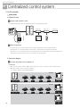
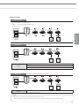
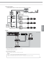
5) Connection diagram
Connection with DVM S series outdoor unit
(1) Set layer
• When on/off controller controls 1 DVM S outdoor unit, then it can be connected to outdoor unit’s F1/F2 line.
• Max.16 Controller can be connected to F1/F2 line.
7 Controller : On/Off controller - MCM-A202DN
Set layer
F1 F2
R1 R2
F1 F2
F1 F2
F1 F2
F1 F2
Set layer
F1 F2
32
R1 R2
F1 F2
F1 F2
F1 F2
F1 F2
(2) Control layer
• When on/off controller control multiple DVM S outdoor units, then it should be connected to R1/R2 line of outdoor units.
• Max.16 Controllers can be connected to R1/R2 line.
7 Controller : On/Off controller - MCM-A202DN
DMS2 - MIM-D00AN (only 1 DMS2 can be connected)
R1 R2
F1 F2
F1 F2
F1 F2
F1 F2
F1 F2
R1 R2
F1 F2
F1 F2
F1 F2
F1 F2
F1 F2
F1 F2
CENTRALIZED
CONTROL SYSTEM
F1 F2
Control layer
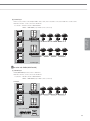
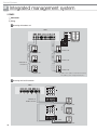
Connection with DMS2 (MIM-D00AN)
(1) Control layer
• DMS2(MIM-D00AN) should connect to R1/R2 line.
• Max.16 Controllers can be connected to R1/R2 line.
7 Controller : On/Off controller - MCM-A202DN
DMS2 - MIM-D00AN (only 1 DMS2 can be connected)
f Case1
F1 F2
R1 R2
F1 F2
R1 R2
F1 F2
F1 F2
DMS2 (MIM-D00AN)
Control layer
33
Control Systems
,,
Centralized control system
2. On/Off controller
MCM-A202DN
5) Connection diagram
Connection with DMS2 (MIM-D00AN)
f Case2
F1 F2
R1 R2
F1 F2
R1 R2
F1 F2
F1 F2
F1 F2
F1 F2
DMS2 (MIM-D00AN)
Control layer
f Caution
• If on/off controller is connected to outdoor unit’s F1/F2 line, DMS2 cannot connect to on/off controller’s R1/R2.
Set layer
F1 F2
R1 R2
F1 F2
F1 F2
F1 F2
F1 F2
DMS2 must connect to control layer.
DMS2 (MIM-D00AN)
34
6) Display
Various LED display
After power reset to the On/Off controller, it carries out indoor unit tracking process.
Address : 1
Main : 0
RMC(1) : 1
RMC(2) : 0
Main : 1
RMC(1) : 1
RMC(2) : 1
Main : 2
RMC(1) : 1
RMC(2) : 2
Main : 0
RMC(1) : 1
RMC(2) : 3
Main : 1
RMC(1) : 1
RMC(2) : 4
Main : 2
RMC(1) : 1
RMC(2) : 5
Main : 0
RMC(1) : 2
RMC(2) : 6
Main : 1
RMC(1) : 2
RMC(2) : 7
Main : 2
RMC(1) : 2
RMC(2) : 8
R1/R2
CENTRALIZED
CONTROL SYSTEM
R1/R2
R1/R2
(1) On/Off controller only communicate with indoor units which has same RMC(1) address with On/off
controller's address.
(2) During tracking indoor units, LED whose number is equivalent to indoor unit RMC(2) address flickers.
• In LED 00 LED 01 LED 02 LED 03 LED 04 LED 05 order
35
Control Systems
,,
Centralized control system
3. Operation mode selection switch
MCM-C200
1) Features
Operation mode selection switch
• Outdoor unit operation mode selection (Cooling, Heating or Auto)
Ú Mixed operation mode protection
(Unit : mm)
2) Installation
• 1 operation mode selection switch must be connected to 1 outdoor unit.
Ú Max. distance between the outdoor unit PCB and the MCM-200: 100m
36
3) Control example
Initial condition
C
• Cool/Heat Selector : Heating position
• IDU1, 2, 3 : Stop mode, IDU4 : Heating mode
• Compressor ON
CENTRALIZED
CONTROL SYSTEM
Sequence 1
Set the Cool/Heat selector to the Cooling position
① Change Cool/Heat Selector to Cooling
Result
② Automatically compressor OFF
③ Running IDU4 stops
Sequence 2
Result
Set IDU4 to Heating with Remote controller
① • IDU4 ignores Heating command
• IDU4 keeps OFF status.
; Note
Operation mode selection switch fixed indoor unit operation mode.
Indoor unit ignores opposite operation mode. (It will not accept the command and it will just beep shortly)
37
'90&21752/
6<67(06
38
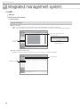
,,,
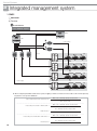
Integrated management systems
1 DMS2 . . . . . . . . . . . . . . . . . . . . . . . . . . . . 2 S-NET3. . . . . . . . . . . . . . . . . . . . . . . . . . . INTEGRATED
MANAGEMENT SYSTEM
39
Control Systems
,,,
Integrated management system
1. DMS2
MIM-D00AN
1) Features
• Built-in web server for PC-independent management and remote access control
• Multiple upper-layer control access (S-NET 3, Web-client)
• Weekly/Daily schedule control
• Power distribution function
• Current time management even during power failure (for 24 hours)
• Emergency stop function with simple contact interface
• Individual/Group control of up to 256 indoor units and ERV, AHU
• User editable control logic
• Accessible level management
• Dynamic security management
• Operation & error history management
• Data storage in non-volatile memory & SD memory
(Unit : mm)
2) Product specification
Source
Power
DC Adaptor
Input
100~240V AC (+-10%), 50/60Hz
Output
12V 3A
Operating temperature range
Operating humidity range
Communication method
-10℃ ~ 50℃
10%RH ~ 90%RH
Lower level : RS485 (Outdoor unit / On/Off controller, PIM)
Upper level : Ethernet 100 Base-T (S-NET3, Web Browser)
Compatible devices
Type
Model
Outdoor unit
Controller
40
DVM S series only
On/Off
controller
MCM-A202DN
PIM
MIM-B16
Upper level controller
S-NET3
Watt-meter
Pulse-type
7 ERV cannot be connected until end of 2013
Maximum device connection
Remarks
E
ach communication channel :
16 units (Max. 128 indoor units)
Max. 80 outdoor units
(Max. 256 indoor units)
Can not connect interface module
(ex. MIM-B13D, MIM-B13D, MIM-B04A)
Each communication channel : 15 units
Max. 75 controllers
Can not connect interface module (ex. MCMA202D, MCM-A202B, MCM-A202A, MCM-A202)
8 units
-
Connected with PIM
Pulse width:20~400(ms)
Pulse :1~10000(Wh/pulse)
To use multiple number of upper level
controllers, HUB or other network
environment must be established
-
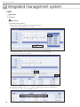
3) Description of parts
Front
No
Function
Name
①
LCD display
②
LCD operation button
③
LED Indicator
④
DMS2 Bottom cover
①
②
③
④
Shows current time and IP address.
Various messages will be displayed
depending on button input.
There are 4 buttons (Menu,
T(Down), S(Up), Set) and you can
access to menu and move, check
the menu.
Check 15 LED status such as Power,
CPU-Alive, Ethernet-Linked/Active,
COM1~5-TX/RX and Check
Unfasten 2 screws on the bottom
and separate the bottom cover from
DMS2.
Then check cable connection part.
INTEGRATED
MANAGEMENT SYSTEM
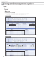
LED indicator
Item
Power
Name
Status
Power indicator
Turns blue when the power is supplied
CPU operation indicator
Blinks in orange with 1 second intervals during
normal operation
Ethernet - Linked
Internet connection indicator
Turns green during normal connection
Ethernet - Active
Internet data transmission/
reception indicator
Blinks in orange during normal transmission/
reception
COM1~5 - TX
On/Off controller/Outdoor unit data
transmission indicator
Blinks in green during normal transmission
COM1~5 - RX
On/Off controller/Outdoor unit data
reception indicator
Blinks in green during normal reception
Indoor/outdoor unit/
error check indicator
Turns green when there is an error on more than
one indoor/outdoor unit or in communication
CPU Alive
Check
41
Control Systems
,,,
Integrated management system
1. DMS2
MIM-D00AN
3) Description of parts
Bottom
DI Terminal2
DO Terminal1
Connect Digital Input
: Channel 6~Channel10
Connect Digital Output
: Channel 1~Channel 5
DO Terminal 2
DI Terminal1
Connect Digital Output
: Channel 6~Channel 10
Connect Digital Input
: Channel 1~Channel 5
Power Terminal
RS485 Communication
terminal
Connect DMS2 adapter
Connect for RS485
communication with devices
such as On/Off controller/
Outdoor units/PIM
Channel 0 ~ Channel 4
Reset Button
Reset DMS2
Cable tie groove
Arrange cables
connected to DMS2
Serial Terminal
Service agent checks
error status
LAN Terminal
Connect LAN cable
SD Card Socket
Socket for sub memory (SD or MMC)
(Sub memory is for DMS2 program update and set information saving)
Ú Purchase SD card separately.
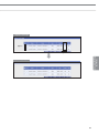
Menu and display
DMS2 IP
Current time
Detail description
Button
LCD display
General display : Displays IP address of the DMS2 and current time
In Menu : Displays menu information and set value
Access menu and select main menu
Cancel menu setting
Move between menu
Change the menu settings
Move between menu
Change the menu settings
42
Access sub menu
Save the change of menu settings
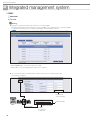
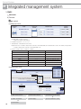
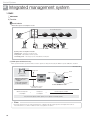
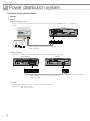
4) Connection diagram
f MIM-B16(PIM) should be connected separately with outdoor unit or controllers.
For power distribution
On/Off
controller
PIM
DMS2
Power line
R1-R2
F1-F2
R1-R2
F1-F2
Watt-hour meter
R1-R2
INTEGRATED
MANAGEMENT SYSTEM
Electrical
substation
F1-F2
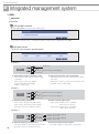
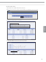
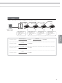
5) Wiring
(CH = Channel)
F1 F2
R1 R2
F1 F2
R1 R2
(1) Connecting outdoor unit directly
• Maximum 16 outdoor units can be connected to each channel
• Total 80 outdoor units can be connected
(2) Connecting On/Off controller
• Maximum 15 On/Off controller can be connected to each channel
; Note
DMS2 can connect outdoor unit and On/Off controller at the same time.
Outdoor unit and On/Off controller can be connected to 1 communication channel at the same time.
43
Control Systems
,,,
Integrated management system
2. DMS2
MIM-D00AN
5) Wiring
Connecting with outdoor unit
DMS2
F1 F2
R1 R2
R1R2
R1R2
Outdoor unit
0
0
Outdoor unit
1
Outdoor unit
R1R2
R1R2
Outdoor unit
1
Maximum 16
connections
Outdoor unit
F
Outdoor unit
F
Outdoor unit
Ú Outdoor unit's address is defined automatically.
The address can be changed manually also.
Connecting with On/Off controller
DMS2
Maximum 15
On/Off controllers
R1R2
Outdoor unit
Outdoor unit
R1R2
Outdoor unit
44
Connecting with outdoor unit and on/off controller
Maximum 16
outdoor units
R1R2
DMS2
1
R1R2
Outdoor unit
R1R2
INTEGRATED
MANAGEMENT SYSTEM
2
Outdoor unit
3
Outdoor unit
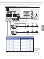
Wiring distance
ⓐ
ⓑ
ⓒ
ⓓ
Maximum 15 On/Off controllers and
16 outdoor units can be connected
to 1 channel of the DMS2
Network radius
ⓔ
f Distance between DMS2 and On/Off controller/outdoor unit
• Distance from the DMS2 to the furthest device cannot exceed 1000m.
•ⓒ + ⓓ + ⓔ d 1000m
f Distance between DMS2 and upper level controller
• Since DMS2 supports 100 Base-T Ethernet, first repeater or upper level controller from the DMS2 cannot be further than 100m
(IEEE 802.3). Therefore, maximum network radius is restricted to 500m.
ⓐ, ⓑ, ⓒ, ⓓ, ⓔ = 100m
ⓐ
ⓑ
ⓒ
ⓓ
ⓔ
HUB
Repeater
ⓐ 500m
Maximum number of repeaters = 4
45
Control Systems
,,,
Integrated management system
1. DMS2
MIM-D00AN
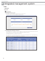
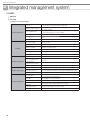
6) Function
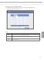
Tracking
f Tracking is an operation that finds devices which are connected to DMS2.
Through tracking operation, devices which are connected to DMS2 can recognize if they are connecting to DMS2.
To supervise and control system air conditioner using DMS2, tracking should be done first.
• When outdoor unit or controller is connected to channel, set as “NEW”
• When PIM(MIM-B16) is connected to channel, set as “IM”
• PIM should be connected separately with outdoor unit or controllers.
f You can check the number of installed devices, address of the devices or rename the indoor unit
after tracking is completed.
Indoor unit name
-> User can modify it.
Indoor unit address
DMS2
Outdoor unit address
Channel number
46
Device type
16 : outdoor unit
32 : Indoor unit
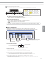
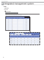
Control & monitoring
f DMS2 can control and monitor Max 256 devices. (Indoor unit, ERV, AHU)
And it also controls and monitors external contact point (8 Digital input, 6 Digital output.)
INTEGRATED
MANAGEMENT SYSTEM
Monitoring
Indoor unit, ERV, AHU
External contact point
Control
Variable web remote controllers
depends on device type.
Multiple language support
f DMS2 (MIM-D00AN) supports 12 languages
Set silent contol
f DMS2(MIM-D00AN) can contol indoor unit without operation beeping sound using below setting option.
• Control and Monitoring: Select this if you want to control silently in 'Control and Monitoring' screen of DMS2.
• Schedule : Select this if you want to perform 'Schedule' silently.
• Control logic : Select this if you want to perform 'Control logic' silently.
47
Control Systems
,,,
Integrated management system
1. DMS2
MIM-D00AN
6) Function
On/Off controller restriction
f DMS2 (MIM-D00AN) can restrict on/off controller usage.
• Select this if you want to restrict controlling from On/Off controllers when you disable RC from the DMS2.
Contact point control
f You can select emergency operation pattern
(1) Pattern 2
No function
Patter 2
External contact (Level-triggered)
f Open external contact : Resume operation
f Short external contact : Emergency stop
• Turns off all the indoor units when there is an ON
signal input
• All the remote control use is disabled
• Control from S-NET3 is unavailable
• Disable schedule control
• After Emergency stop, the indoor units stay in the current
OFF states.
• All the remote control use is restored to the previous state.
• Schedule control is enabled again.
(2) Pattern 3
External contact (Level-triggered)
Pattern 3
External contact (Level-triggered)
f External contact input to DI-1
• Short contact : Starts all indoor unit operation.
• Open contact : Stops all indoor unit operation.
Ú Schedule control is not interrupted in Pattern 3.
f External contact input to DI-2
• Short contact : Disables the use of all wired/
wireless remote controllers.
• Open contact : Enables the use of all wired/
wireless remote controllers.
(3) Pattern 4
Pattern 4
f External contact pulse input to DI-1
• Short pulse-triggered : Starts all indoor unit operation.
48
Ú Schedule control is not interrupted in Pattern 4.
External contact (Pulse-triggered)
Duration : 0.5~1.0 sec
External contact (Pulse-triggered)
Duration : 0.5~1.0 sec
f External contact pulse input to DI-2
• Short pulse-triggered : Stops all indoor unit operation.
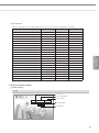
General external contact point control
DMS2 has Digital input/output ports to check the external device status or turn them On/Off through contact point.
Digital input
Digital Output
Channel 1
Channel 10 Channel 1
Channel 10
f DI : Voltage free contact signal input (Open / Short)
• Channel 1, Channel 2 is occupied with [Emergency stop] function.
• Channel 3~Channel 10 : DMS2 can monitor the contact signal input state of each channel
f DO : Contact signal output (DC 12V)
• Channel 1, Channel 2, Channel 9 and Channel 10 is occupied with other functions.
• Channel 3~Channel 8 : DMS2 can control contact signal output.
; Note
DI 1, 2/ DO 1, 2, 9, 10 will be excluded from control and monitoring since it is being used by internal function of DMS2.
INTEGRATED
MANAGEMENT SYSTEM
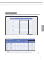
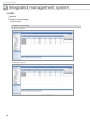
Indoor unit usage restriction
• Operation limit : To prevent the wrong operation mode setting, it can limit the operation mode of indoor unit.
• Temperature limit : It can set the lower temperature limit in Cool mode and the upper temperature limit in Heat mode.
❸ Control mode
❶ Indoor unit address
❷ Operation mode
restriction
❶ Check the indoor unit address.
Virtual on/off controller
(11~15. Depends on channel number)
❹ Setting Upper temperature limit in Heating,
Lower temperature limit in Cooling
Outdoor unit
Indoor unit main address
Indoor unit group address (RMC(2))
❷ Select the Limit mode
• Indoor units within same outdoor unit must be set in same limit mode.
• All indoor units of one outdoor unit set same operation mode restriction automatically.
❸ Control mode will be set automatically depends on the seleceted restricted mode
• Ex) When the restricted mode is set to [Cool-only] and then [Control mode] is set to [Cool] automatically
If user set [Heating mode] using remote controller Indoor unit ignores the command.
❹ Set the Upper temperature limit in Heating and Lower temperature limit in Cooling.
• Upper temperature limit in Heating and Lower temperature limit in Cooling can be set differently for each indoor unit.
(Cooling:18ºC~30 ºC, Heating:16 ºC~30 ºC)
49
Control Systems
,,,
Integrated management system
1. DMS2
MIM-D00AN
6) Function
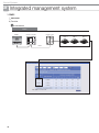
Logic control
What is logic control?
User can control the air conditioner, ERV, AHU and digital output depending on the conditions, such as room temperature and
outdoor temperature, set by the user. Input condition can be used with parameter and it will be calculated with arithmetic equation.
Schedule function executes operation by time but logic control executes operation according to the conditions that set by the user.
Examples of utilizing the logic control
Case 1) Government regulates the lowest room temperature to be 26ºC in public places. When the room temperature is lower than
26ºC, administrator must turn off all the air conditioners in the area. Is there any way for the air conditioner to turn off
automatically depending on the certain room temperature?
Case2) During spring and fall, it is cold in the morning and warm in the afternoon. Therefore, I’m using the air conditioner in heating
mode in the morning and cooling mode in the afternoon. Can I set the air conditioner to change operation mode automatically
depending on the outdoor temperature?
Case 3) I’m using air conditioner with ERV. In the days with the outdoor temperature relatively lower than the indoor, I want to use
ERV instead of the air conditioner to ventilate and minimize the air conditioner use. Is there any way to set the air conditioner
or ERV to operate appropriately and automatically depending on the temperature?
Input
Output
1. Select the factor to input condition
Device, factor
2. Edit the condition
Compound factor
Comparison operator
Standard value
Duration
¨
Edit factor
Single
factor
50
1. Select output factor
Device, factor
Power
Current temp.
Desired temp.
Outdoor temp.
Mode
Fan speed
Air flow
Enable/Disable RC
Arithmetic
factor
+
-
Current temp.
Desired temp.
Outdoor temp.
Function
factor
Average
Current temp.
Desired temp.
Outdoor temp.
2. Edit output
Create control
Compound
factor
Comparison
operator
AND
=
OR
=>
Desired
temp.
=<
Mode
>
Fan speed
<
Air swing
z
Enable/
Disable RC
Command
Power
(1) Editing input factor
④
②
③
⑤
⑥
⑧
⑦
⑨
①
¨
② Select type of the factor
¨
INTEGRATED
MANAGEMENT SYSTEM
① Click “Select a factor”.
③ Click “Select a device”
ª
⑥ Click “Apply”.
§
⑤ Select a detail item
§
④ Select the device from the list.
⑧ Select a standard value
¨
⑨ Select the duration
ª
⑦ Select the comparison operator ¨
f Single factor : 1 device and 1 factor.
f Arithmetic : It means 2 devices are connected by arithmetic operator.
f Function : Use average value of various conditions from the device and create it as a factor.
51
Control Systems
,,,
Integrated management system
1. DMS2
MIM-D00AN
6) Function
Logic control
(1) Editing input factor
• Compound factor : AND, OR, No selection
Ex) Apply 'AND' or 'OR' to 3 factors
(input 1) And (input 2) OR (input 3)
• Comparison operator : =, =>, =<, <, >, z
• Standard value : Standard value of the factor
Ex) When the factor is “Outdoor temperature of the indoor unit number 00”, then standard value is value of the “Outdoor temperature”.
“Outdoor temperature of the indoor unit number 00” > 20
• Duration : Duration can be set between 1~60 min.
Item
Comparison operator
Power
=, z
Standard value
On, Off
Current temp
=, =>, =<, <, >, z
Temperature value (number)
Desired temp
=, =>, =<, <, >, z
Temperature value (number)
Outside temp
=, =>, =<, <, >, z
Temperature value (number)
Mode
=, z
Auto, Cool, Dry, Fan, Heat
Fan speed
=, z
Auto, Low, Med, High
Air flow
=, z
Vertical, Horizontal, All, None
Enable RC
=, z
ON, OFF, Level 1
(2) Editing output factor
③
Only ‘Single’ will be listed
②
④
“Current temp.” and “Outdoor temp.”
cannot be selected
①
⑤
⑥
⑦
① Click “Select a factor”.
¨ ② Click “Select a device”.
¨ ③ Select the device from the list.
ª
⑥ Select “Command”.
ª
⑦ Click “Save”.
52
§ ⑤ Click “Apply”.
§ ④ Select a detail item to control.
(3) Control example – Setting
Ex) Set the ERV to turn off together when the indoor unit turns off
❶ Click [Control logic management] [Setting control logic] from DMS2 menu. Click [Register] to create new control logic.
❷ Enter Name, period/day and time for new control logic.
INTEGRATED
MANAGEMENT SYSTEM
❸ Create input condition : Click [Select a factor] from the ‘Input’ window.
53
Control Systems
,,,
Integrated management system
1. DMS2
MIM-D00AN
6) Function
Logic control
(3) Control example – Setting
❹ Click [Select a device], then [Device selection] window will pop up.
Select a indoor unit to apply the new control logic.
❺ Create input condition : When the device is selected, click [Power] and click [Apply].
Ú [Power] means the operation state (On/Off).
❻ Create input condition : Select ‘=’ as a comparison operator and select “Off” as a standard value.
• Meaning: Execute output control when 00.00.00 device is off.
54
❼ Create output : From the output window, select the device to apply the control when input condition is satisfied.
Click [Apply] when selection is completed.
INTEGRATED
MANAGEMENT SYSTEM
❽ Create output : Select “Power” as a factor of the selected device and click [Apply].
❾ Create output : From the output window, select the control to be executed when input condition is satisfied.
• Turn off the ERV no. 0
❿ Click [Save] when the setting is completed.
To apply the new logic control, select the created logic and click [Apply].
55
Control Systems
,,,
Integrated management system
1. DMS2
MIM-D00AN
6) Function
Logic control
(4) Control example – Control logic
Ex) Control logic 1 : Turn on 4 indoor units when outdoor temperature is 30°C or higher.
Control logic 2 : Turn off 4 indoor units when outdoor temperature is 26°C.
Control logic 1
❶ Input : When outdoor temperature is 30°C or higher.
❷ When condition 1 lasted for 5 miniute. ❸ Output : Turn on 4 indoor units.
Control logic 2
56
❶ Input : When outdoor temperature is 26°C or lower.
❷ Output : Turn off 4 indoor units.
Register control logic
➊ Click
➋ Click
INTEGRATED
MANAGEMENT SYSTEM
Control logic applied
Application completed
57
Control Systems
,,,
Integrated management system
1. DMS2
MIM-D00AN
6) Function
Power distribution
• Where does power consumption occurs?
Air-conditioning system
Outdoor unit fan
Compressor
Outdoor unit PCB
Indoor unit PCB
Indoor unit fan
System power consumption includes:
1. Main power - Compressor operation power
2. Fan power - Indoor/Outdoor unit fan operation
3. Stand-by power - Preheating coil power, Indoor/Outdoor PCB power
(1) DMS2 power distribution theory
All the system information of power and indoor/outdoor operation is always monitored by the DMS2 for power distribution calculation.
IDU: Indoor unit
Through PIM
IDU B
IDU A
Measured power
consumption
IDU C
Operation information
1. Outdoor/Indoor unit
operation
2. Indoor unit fan operation
3. Stand-by operation
IDU D
Power distribution result
Through On/Off controllers
and interface modules
IDU A’s electric power
consumption
=
Total power
consumption
x
Demand capacity of IDU A
Total demand capacity of all IDUs
Here, Demand capacity = Main capacity + Fan capacity + Stand-by capacity
; Note
Demand capacity means the value that parameters of different units like required power and refrigerant amount are
transformed into as a common number to make easy algebraic calculation.
58
(2) Main capacity
This is determined dynamically with the combination of various refrigerating parameters such as difference between room and set
temperature or evaporator input/output temperature.
These parameters, as a result, determine the refrigerant amount flowing into the indoor unit by controlling EEV steps.
(3) Fan capacity
This is constant value for indoor unit models. It differs depending on indoor units of different capacity.
When the indoor unit starts Cooling, Heating, Auto and Fan modes, fan capacity values of the indoor units are always monitored by
the DMS2. DMS2 gathers capacity of zero value when they stop operating.
(4) Stand-by capacity
Stand-by capacity is constant for all indoor units regardless of their operations. Since stand-by power is consumed all the time by
PCBs and preheating coils in the outdoor unit, whose value is monitored with the same fraction which is relatively small compared to main
capacity or fan capacity.
(5) What if the room temperature begins to reach the set temperature?
If the room temperature begins to reach the set temperature, the indoor unit does not have to extract the full refrigerant amount to
keep the set condition. Capacity from the indoor unit goes down to indicate the outdoor unit that it does not need refrigerant at the
full capacity state.
INTEGRATED
MANAGEMENT SYSTEM
When the room temperature has reached the set temperature, there is no need to pump the refrigerant into the indoor unit. Indoor unit
goes into the thermally OFF state and sends capacity of zero value to the outdoor unit and the DMS2, which results in fan or stand-by
power distribution only.
(6) Capacity accumulation and power distribution
DMS2 gathers power consumption and capacity values during one-day.
At midnight, 1-day power consumption is distributed to the indoor units using the gathered information.
00:00
24:00
24-hour
1. Calculates consumed power for 1 day.
2. Calculates accumulated capacity values
3. Distributes 1-day power consumption
4. Clears accumulated capacity values
During 24 hours,
1. Reads every indoor unit operation
2. Reads watt-hour meter value
3. Accumulates 3 capacity values
(7) Undesirable situation protection
Even when there occurred communication error between the DMS2 and PIM or DMS2 can no longer gather power consumption,
DMS2 stores power distribution ratio for all indoor units. As soon as communication between them resumes and power information is
transmitted to the DMS2, power distribution during the interrupted period is recovered as normal condition.
(8) Not equal stand-by power distribution (In case all the indoor units are stopped)
Since there always exists error in each power consumption amount, distributed stand-by power may not be equal for different
air-conditioning system. But the difference is so small that it is negligible.
Run
Stop
A
Stop
B
C
Stop
Stop
D
E
B = C, D = E
BzD
59
Control Systems
,,,
Integrated management system
1. DMS2
MIM-D00AN
6) Function
Power distribution
Power distribution equation
DMS2
PIM
Power supply
G4
R1/R2
G3
G2
Power supply
G1
f When configuring the DMS2 and the whole system, mapping of watt-hour meters for indoor/outdoor units must be precisely
assigned for correct power distribution.
Main + Fan + Stand-by capacity of indoor unit X
Indoor unit power X in G1 = Watt-hour A x
Total capacity of G1
Main + Fan + Stand-by capacity of indoor unit X
Indoor unit power X in G2 = Watt-hour B x
Total capacity of G2
Fan + Stand-by capacity of indoor unit X
+ Watt-hour D x
Total Fan/Stand-by capacity of G2
Main + Fan + Stand-by capacity of indoor unit X
Indoor unit power X in G3+G4 = Watt-hour C x
Total capacity of G3 + G4
Fan + Stand-by capacity of indoor unit X
+ Watt-hour E x
60
Total Fan/Stand-by capacity of G3 + G4
Example
Suppose capacity values accumulated at 24:00 during one whole day is as follows.
Strong
cooling
Week cooling
Fan mode
Stop
360kWh consumed
(outdoor + indoor)
Pd of Indoor unit A =
Indoor unit capacity
Total capacity
Pd of Indoor unit B =
85 x 360
130 + 85 + 25 + 5
Pd of Indoor unit C =
25 x 360
130 + 85 + 25 + 5
Pd of Indoor unit D =
5 x 360
130 + 85 + 25 + 5
Main capacity = 60
Fan capacity = 20
Stand-by capacity = 5
Sum = 85
x Total kWh =
Main capacity = 0
Fan capacity = 20
Stand-by capacity = 5
Sum = 25
130 x 360
130 + 85 + 25 + 5
Main capacity = 0
Fan capacity = 0
Stand-by capacity = 5
Sum = 5
INTEGRATED
MANAGEMENT SYSTEM
Main capacity =105
Fan capacity = 20
Stand-by capacity = 5
Sum = 130
= 192.020 kWh
= 124.900 kWh
= 36.735 kWh
= 7.347 kWh
61
Control Systems
,,,
Integrated management system
1. DMS2
MIM-D00AN
6) Function
Power distribution
Installation example (Allowed)
DMS2
PIM
Power supply
R1/R2
G4
G3
G2
Power supply
G1
Mapping watt-hour meters to indoor/outdoor units
• Watt-hour meter A is mapped to all indoor/outdoor units in G1.
• Watt-hour meter B is mapped to the outdoor unit in G2.
• Watt-hour meter C is mapped to the outdoor units in G3 and G4.
• Watt-hour meter D is mapped to the indoor units in G2 + G3.
• Watt-hour meter E is mapped to the indoor units in G4.
Ú Installation above is allowed with proper mapping configuration.
; Note
Watt-hour meter can be shared to the multiple indoor/outdoor systems.
62
Installation example (Not allowed)
DMS2
PIM
Power supply
G4
INTEGRATED
MANAGEMENT SYSTEM
R1/R2
G3
G2
Power supply
G1
All indoor units in one outdoor unit must have the same power source.
• Installation above cannot be available for the reason that one indoor unit in G1 has different power source from the other indoor units.
In this case, fractional power of D consumed by the separate-powered indoor unit in G1 is distributed to the indoor units in G2 and G3.
63
Control Systems
,,,
Integrated management system
1. DMS2
MIM-D00AN
6) Function
Power distribution
(10) Setting the inspection section
If you want to check the distribution result by time period, set the time section.
You must use S-NET3 to check the distribution result by time period.
(11) Setting the power distribution environment
This is important task for checking precise energy consumption of the outdoor/indoor unit. Each watt-hour meter connected to
outdoor unit must be checked for which channel of the PIM interface module it is connected.
Then PIM channel must be set according to the outdoor unit.
Indoor units must be checked which watt-hour meter it is connected to and then PIM channel of the corresponding watt-hour
meter must be set according to indoor unit PIM channel as shown below.
64
Example of watt hour meter installation ❶
Installing watt-hour meter to outdoor/ indoor unit
Main circuit breaker
PIM
Address 0
Watt-hour meter A
Watt-hour meter B
Watt-hour meter C
Watt-hour meter D
CH1
CH2
CH3
CH4
R1/R2
A/B
B
C
D
1 phase power
1
2
INTEGRATED
MANAGEMENT SYSTEM
0
F1/F2
Pipe
connection
R1/R2
A
0
1
2
F1/F2
3 phase power
Pipe
connection
Ú Connect appropriate watt-hour meter to outdoor/ indoor unit.
65
Control Systems
,,,
Integrated management system
1. DMS2
MIM-D00AN
6) Function
Power distribution
Example of watt hour meter installation ❷
Installing 1 watt-hour meter to all indoor units
Main circuit breaker
PIM
Address 0
A
B
Watt-hour meter A
Watt-hour meter B
Watt-hour meter C
Watt-hour meter D
CH1
CH2
CH3
CH4
C
R1/R2
A/ B
1 phase power
0
1
2
R1/R2
F1/F2
0
1
Pipe
connection
2
F1/F2
Pipe
connection
3 phase power
Since all indoor units
are connected to 1
watt-hour meter, PIM
channel address of all
indoor units is same.
66
Example of watt hour meter installation ❸
Using CT watt-hour meter to and outdoor unit
Main circuit breaker
RS T N
PIM
5: 1
5: 1
Address 0
5: 1
B
C
D
Watt-hour meter A
Watt-hour meter B
Watt-hour meter C
Watt-hour meter D
CT-type watt-hour meter
CH1
CH2
CH3
CH4
3 phase 4 wire voltage
1 phase power
0
1
2
Pipe
connection
0
1
2
F1/F2
Pipe
connection
3 phase power
[Setting and checking
watt-hour meter]
From the menu, CT
proportion of the CT
watt-hour meter must
be entered.
; Note
• After entering CT proportion of the CT watt-hour meter, watt-hour meter must be set to correct outdoor/indoor units
from the [Channel setting by indoor unit] window.
67
INTEGRATED
MANAGEMENT SYSTEM
F1/F2
R1/R2
A
R1/R2
R1/R2
Control Systems
,,,
Integrated management system
1. DMS2
MIM-D00AN
6) Function
Power distribution
Checking the watt-hour meter connection
Kilowatthour history of the watt-hour meter, connected to each PIM interface module, can be checked.
Maximum 365 days worth of Kilowatthour history can be checked.
68
Setting virtual watt-hour meter
When watt-hour meter or PIM interface module is not installed to a watt-hour meter channel, virtual channel can be used to manually
distribute the power distribution
INTEGRATED
MANAGEMENT SYSTEM
• Maximum 128 virtual channel can be used.
• Address of the virtual channel will be displayed as following.
(24~31).(1~16)
; Note
• When PIM interface module is not installed, PIM channel of the outdoor/indoor unit will be inactive.
69
Control Systems
,,,
Integrated management system
1. DMS2
MIM-D00AN
6) Function
Power distribution
Caution
Power distribution function is only supported to air conditioners and AHU. ERV is not supported.
DMS2
On/Off controller
Outdoor unit
R1R2
Only applies to indoor unit
70
Main 0
RMC 0
Main 1
RMC 1
Main 2
RMC 2
User authorization management
INTEGRATED
MANAGEMENT SYSTEM
• Admin (Administrator) : Can access all menus, accessible menu cannot be changed
• Manager : Default setting – Can access all menus, accessible menu can be changed.
• Regular user : Default setting – Can access [Control and monitoring] menu only.
Editing user authorization
• Accessible menu authorization of manager is editable.
Select/deselect the checkbox of the function and save the setting to change the authorization.
71
Control Systems
,,,
Integrated management system
1. DMS2
MIM-D00AN
6) Function
User management
f You can add or delete the user who access DMS2 through web.
f Authorization of the added user can be set from [Admin], [Manager], [Regular user].
72
Zone management
• Zone edit: User can arrange the indoor units for convenient management.
• Setting the user authorization: Can restrict accessible indoor units depending on the user ID.
Zone edit
INTEGRATED
MANAGEMENT SYSTEM
Initial setting
Zone edit :
Add, delete zone
Change name
Move indoor unit
73
Control Systems
,,,
Integrated management system
1. DMS2
MIM-D00AN
6) Function
Setting the user authorization
f Authorization to control and monitor a zone of indoor units can be assigned according to User ID
❶ Select the zone and select a user ID who can access the zone.
• Access authorization can be set by zone.
❷ After setting, click [Save] to complete the authorization setting.
f User access authorization applies to all indoor units of the zone in same manager.
74
2. S-NET3
MST-P3P
1) Features
PC program designed to manage system air
conditioners in a large site.
Max. 16 DMS2 connection
Max. 4,096 indoor unit controlling and monitoring
Integrated management of indoor units, ventilators
and AHU
Manages operation and error history
Check indoor/outdoor unit cycle data
Integrated management of peak control in single program
INTEGRATED
MANAGEMENT SYSTEM
2) PC specifications
Item
PC
Model
Details
CPU
Pentium 4 or above
Memory
More than 512MB
HDD
More than 1Gbyte space available
Network
10/100M
Model
MST-P3P
-
Windows NT, Windows 2000, Windows XP,
Windows VISTA, Windows 7
Number of connection
Max. 16 DMSs
OS
; Note
3) System connection
S-NET 3
On/Off
controller
Indoor/Outdoor units
DMS2
HUB
Internet
75
Control Systems
,,,
Integrated management system
2. S-NET3
MST-P3P
4) Function
(1) S-NET3 function description
View the management
structure
View the installation structure
Control & Monitoring
Indoor unit/ERV control
Control and monitor the indoor units (max. 4,096 units).
Check and refer the state of various devices such as indoor/outdoor units, On/
Off controller, and I/M.
Set the operation mode, temperature, fan speed, and fan
Control & Monitoring direction of indoor unit/ERV.
Indoor unit/ERV monitoring
Monitor the status of indoor unit/ERV.
View outdoor unit
Check the outdoor unit’s cycle data and the cycle data of the linked indoor
units.
View DMS2
Check the status data of the control unit linked to DMS2.
Create new schedule
Set new schedule.
View schedule
Check the schedule of the selected indoor unit.
Start/Stop schedule
Start/Stop schedule application.
Store/Call schedule
Store/Call a prepared schedule.
View daily schedule
Confirm each schedule by date.
Set common exception date
Set the date which schedule operation is not applied on.
Usage time and power
Check the usage time and power for total, group, and individual indoor units.
Power consumption report
For preparing the report on the power consumption by each indoor unit for the
period set.
Power distribution
management group edition
Edit an indoor unit’s power management structure
Set the electricity rate section
Set up to 3 sections for electricity billing management.
Indoor unit status
Check the status of indoor unit operation / temperature setting per period.
Usage time and power
Check the usage time and power for total, group, and individual indoor units.
Schedule
Usage time and power
Statistics and analysis
System management
76
Indoor unit usage
The usage ratio of all indoor units for a specific period.
Set environment
Set the environment related to S-NET3
(password, language, temperature unit).
Set DMS2
Set the DMS2 to connect with S-NET3.
Refer event log
Refer the warning, error, data of indoor units.
Renew installed device
information
Modify S-NET3 data if installation data has been changed.
DMS2 backup/restore
Backup the data of DMS2 connected to S-NET3.
S-NET3 backup/restore
Backup the data of S-NET3.
(2) User functions
Manage a range of functions accessible to different types of users such as regular user, administrator and installer.
User
Administrator
Installer
View the total indoor unit
O
O
O
Structure editing
X
O
O
The list of installed devices
X
O
O
Whole indoor unit stop
O
O
O
Indoor unit/ERV control/Monitoring
O
O
O
View the management structure
O
O
O
View the installation structure
X
O
O
View outdoor units, DMS2
X
O
O
Schedule
X
O
O
Indoor unit operation setting
X
X
O
X
O
O
X
O
O
Power distribution management group edit
X
O
O
Power distribution section setting
X
X
O
Statistics/Analysis
X
O
O
S-NET3 setting
X
O
O
DMS2 setting
X
X
O
Event log reference
X
O
O
Tracking
X
X
O
DMS2 restoration
X
X
O
DMS2 backup
X
O
O
S-NET3 restoration/backup
X
O
O
INTEGRATED
MANAGEMENT SYSTEM
Usage time and power
Power consumption report
5) Detail function description
(1) S-NET3 display
Log-in
Select user
Select administrator
Select installer
Password input
Login button
77
Control Systems
,,,
Integrated management system
2. S-NET3
MST-P3P
5) Detail function description
(1) S-NET3 display
Control and monitoring
Management structure
monitoring window
Control monitoring window
Move to Indoor
unit control
window
Management
structure/Installation
structure display
window
Indoor unit
control
ERV control
Main menu
window
Log/error display
window
Installation structure window
Select the installation structure tab then select DMS2 connected to S-NET3; it is possible to see the program version, status of the
selected DMS2, the program version and communication status of On/Off controller.
If indoor or outdoor unit is selected at the installation structure, it is possible to check the hardware information of the selected device.
Selecting management structure
Selecting installation structure
f When DMS2 & On/Off controller are selected.
• DMS2 status, DMS2 program version,
last tracking date and Master/Slave setting
state.
• Displays model name, software version,
communication state of centralized
controller, PIM.
78
Installation structure window
f When outdoor unit is selected
INTEGRATED
MANAGEMENT SYSTEM
• Outdoor unit cycle data, outdoor unit model, interface module model and interface module program version is displayed.
f When indoor unit is selected
• Indoor unit operation status, indoor unit cycle data and indoor unit model code is displayed.
79
Control Systems
,,,
Integrated management system
2. S-NET3
MST-P3P
5) Detail function description
(1) S-NET3 display
Installation structure window
f When DI is selected
f When DO is selected
80
Control
• Control indoor unit/ERV through the control window that appears on the screen.
• Control total indoor units, the operation mode of indoor units, multiple selection, temperature, fan speed, and fan direction.
• Set Upper/Lower temperature limit so that temperature cannot be set outside of the limited temperature range.
• Enable/disable remote control usage.
• Check the schedule of the selected indoor unit.
f Selecting indoor unit and ERV together
f Selecting indoor unit
f Selecting ERV
INTEGRATED
MANAGEMENT SYSTEM
f Deselect device
81
Control Systems
,,,
Integrated management system
2. S-NET3
MST-P3P
5) Detail function description
(1) S-NET3 display
Schedule control
❶ Schedule setting
• Able to set a schedule to control indoor units and ERVs. (creating, modifying, deleting).
• Able to set weekly, daily, one day schedule.
• Able to control the operation mode, temperature setting, fan speed, fan direction during the schedule control.
Schedule list
window
Schedule display window
Ú Easy schedule control for user with the wizard method (step-by-step setting).
f The 1st step (select a schedule mode)
One day only
Repeat daily
f The 2nd step (select the indoor units to apply a schedule to)
• Display the total indoor units in S-NET3.
• Able to select individual indoor units, On/Off controller, DMS2.
82
Repeat weekly
Schedule control
f The 3rd step (schedule operation setting)
• Set up time by dragging on the time table.
• Set the schedule with the control panel on the right. (Operation mode. temperature setting, fan speed, fan direction and
remote control use).
• Click the schedule time setup window to display a schedule modification window (able to modify a schedule time,
operation mode and temperature setting).
Control panel
Click twice
INTEGRATED
MANAGEMENT SYSTEM
Time modification
(based on minutes)
Temperature setting
Operation mode
Remote control use
Time setting by dragging
(based on 30-min. unit)
Schedule modification panel
f The 4th step (Schedule period and exception date setting)
• Click the date on the calendar to set the date (once selected, the designated date is displayed in red).
Schedule name
Schedule period setting
Schedule exception
date setting
f Schedule setting completion
• Displays a schedule list to be automatically
applied to the schedule
Display the name of
set schedule.
Display set schedule
83
Control Systems
,,,
Integrated management system
2. S-NET3
MST-P3P
5) Detail function description
(1) S-NET3 display
Schedule control
❷ Schedule modification
• Click the set schedule display window twice to display the modification panel.
Then it is possible to modify various functions such as schedule time, operation mode and temperature setting.
• Able to carry out various functions such as a schedule name change, schedule delete, indoor unit addition and deletion with the icons
on the left menu window.
Add/ Delete indoor unit for schedule control.
Delete a set schedule.
Modify a schedule name.
Usage time and power consumption
❶ Usage time and power
• Able to search for the power consumption and usage time by different conditions including the total indoor units applied to S-NET3,
On/Off controller, individual indoor unit.On/Off controller, individual indoor unit.
Total indoor unit usage reference
Individual indoor unit usage reference
❷ Power consumption report
• Able to print out the amount of power consumed for a specific period of time in the form of report.
• The applicable formats include PDF, TXT, HTML, CSV, MHT, EXCEL, graphic documents.
Types of document to be stored
84
Usage time and power consumption
❸ Power management structure editing
• Just as the structural editing at the monitoring, power management can be restructured to ensure greater convenience for
administrators.
• Once the power management structure is edited, power consumption report and usage can be referred in the edited formats.
Power structure editing menu
Power structure editing window
INTEGRATED
MANAGEMENT SYSTEM
❹ Power section setting
• It can be referred and divided into max. 3 sections for power consumption reference.
• It is possible to refer or prepare reports for usage time and power consumption by dividing section by each hour.
Able to adjust the sections by inputting relevant time.
85
Control Systems
,,,
Integrated management system
2. S-NET3
MST-P3P
5) Detail function description
(1) S-NET3 display
Statistics and analysis
❶ Indoor unit status
• Able to see the operation status of selected indoor units and room temperature for the present and the past.
• Able to refer to the operation status for the last two days. If the reference day is out of range, an error message window will appear.
Hourly indoor unit operation and
temperature display
Select
indoor unit
Display errors if the wrong
period has been set
❷ Power consumption of indoor units
• Displays the use time and power consumption ratios for the indoor units connected to each DMS2.
Period reference
DMS2 selection
86
System management
❶ Environment setting
• Set the environment of S-NET3.
• Set administrator password, language, temperature unit, default value for indoor unit, etc.
• Determine if peak power will be displayed or not in the menu setting (Korean market only).
Language setting
Log date view setting
Temperature unit setting : It is set automatically
depending on indoor unit.
INTEGRATED
MANAGEMENT SYSTEM
❷ DMS2 setting
• Set the DMS2 to connect with S-NET3.
• Click ‘save’ after inputting IP and passwords (1) and it will attempt to make communication with S-NET3 and DMS2 then display
normal when communication is made.
DMS2 setup window
When a DMS2 to connect with
S-NET3 is added
DMS2 time setting
Password input
DMS2’s access IP input
; Note
DMS2 has two passwords. One is a password needed to connect to a DMS2 web client (set at the user management), the other is
necessary to make access to S-NET3 (set at the system environment).
When the wrong password for S-NET3 is input, a message indicating DMS2 – account recognition failure appears.
87
Control Systems
,,,
Integrated management system
2. S-NET3
MST-P3P
5) Detail function description
(1) S-NET3 display
System management
❸ View event log
• Able to check various information such as indoor/outdoor units connected to S-NET3, control device error/warning, information
details by date.
Set the list of events
Query period setting
Event display
❹ Information update of the installed device
• Able to carry out information update or tracking for the installed device.
• Tracking involves receiving data from DMS2 after tracking it so as to renew data, whereas data renewal involves correcting data
from DMS2 after receiving data without DMS2 tracking.
List of control devices connected to DMS2
88
Tracking is under way
System management
❺ DMS2 backup and restoration
• Able to backup and restore the DMS2 data connected to S-NET3.
• Backup refers to activities of storing data in the data folder in PC.
Select all DMS2s
Backup
Restoration
Indicate a backup file including the
directory path
Indicate a backup date
INTEGRATED
MANAGEMENT SYSTEM
❻ S-NET3 backup and restoration
• Able to backup and restore data of S-NET3.
• Backup involves in backing up all data in S-NET3. Thus, if backup data is restored in a PC where S-NET3 is installed,
it will produce the same environment that is previously used.
89
Control Systems
,,,
Integrated management system
2. S-NET3
MST-P3P
5) Detail function description
(2) S-NET3 log information
Log
90
Contents
E9000
Connection impossible
E9001
Connection denied
E9002
Connection finished
E9010
WINK denied
E9011
DMS2 password authentication failure
E9012
Serial exchange failure
E9100
General error on instruction transmission
E9150
Attempt to transmit to a DMS2 not in connection
E9151
Attempt to transmit to a DMS2 not registered
E9200
General error on response acceptance
E9250
There is no response to the requested command due to DMS2 failure and/or network delay
E9300
XML generating
E9400
XML parsing
E9401
Installation information on S-NET3 and DMS2 does not match, check tracking information
E9999
Initialized device information updating device status
I101
Common user log in
I102
Administrator user log in
I103
Installer log in
I104
Log in
I105
Log out
I201
Tracking
I202
Request to tracking
I301
Request to schedule change
I801
Insert DMS2
I802
Delete DMS2
I803
DMS2 time setting
I9700
DMS2 connection and authorization successful
I9701
Reconnection
I9801
Emergency stop
,9
Power distribution system
1 Electricity meter interface module. . . . . . . POWER
DISTRIBUTION SYSTEM
91
Control Systems
,9
Power distribution system
1. Electricity meter interface module
MIM-B16
1) Features
(Unit : mm)
Front view
• Pulse output electricity meter interface unit
(max. 8 meters)
• 8-channel energy consumption display in real time
• System configuration with button manipulation
• Various text messages in LCD
• Current communication state indication
Side view
Power supply (adapter)
Input : 100~240V AC, 50/60Hz, 1.0A
Output : 12V DC, 3.0A
Operating temperature range
-10ºC ~ 50ºC
Operating humidity range
10%RH~90%RH
Maximum wiring length
DMS2 : 1000m
Electricity meter : 200m
Number of interfaces
Electricity meter : max. 8 units
DMS2 : 1 unit
2) Display and buttons
①
②
⑦
③
④
⑤
92
⑥
No.
Name
Description
①
LCD window
Information on current electricity readings, settings and operation state is displayed
(16 character x 2 line LCD).
②
Menu button
Various menus are selected to monitor current electricity readings, to make
configuration settings for electricity meters, and to check the error/settings.
③
Power (blue)
It’s ON when power is supplied normally.
④
Communication (orange)
⑤
Pulse input (orange)
⑥
Communication (orange)
⑦
Check
It blinks when communication between DMS2 and MIM-B16 normally works.
Each of the 8 LEDs blinks whenever a pulse from an electricity meter is detected.
Reserved
It’s ON when errors occur in communication or pulse input from electricity meters.
3) Connectors
①
②
③
No.
④ ⑤
Name
Description
①
Pulse input terminals
8 terminals are allocated to interface pulse-type electricity meters. Each terminal is seen
with a dedicated address on DMS2.
②
Power input
Power supply via the power adapter.
③
Reset button
Press the button to reset the MIM-B16.
④
COM1
Connection terminal for RS485 communication with DMS2.
⑤
COM2
Reserved
4) Address & option switches
SW2
Address switch
SW3
SW4
POWER
DISTRIBUTION SYSTEM
SW1
Option switch
No
Name
Description
1
SW1
No function
2
SW2
MIM-B16 address switch. Address greater than 7 (8~F) is not recognized.
3
SW3
No function
4
SW4
No function
93
Control Systems
,9
Power distribution system
1. Electricity meter interface module
MIM-B16
5) Specifications on electricity meter
• Current flow on output : Current-sinking
• Pulse rate : 1 ~10000 Wh/pulse (no decimal pulse rate allowed)
• Pulse width : 20 ~ 400ms with +/- 5% tolerance (no decimal pulse rate allowed)
• Time interval between pulses : min. 3ms
• Allowable current sinking : min. 15mA
• Withstanding voltage : min. 15V DC
• Interface circuitry : Electronic isolation circuitry recommended, no voltage output
Pulse generation from
electricity meter
Current sink
+
+
Current source
Current flow(max. 15mA)
Current flow
Dead period
+
Withstanding voltage
(max. 15V DC)
Active pulse
Generation period
(current sinking)
Pulse width
Interval between pulse
; Note
Interface circuitry of an electricity meter has to withstand min. 15mA and min. 15V DC, both of which are applied by MIM-B16.
Even though MIM-B16 interface circuitry is realized with electric isolation components, it’s highly recommended that interface
circuitry of an electricity meter be designed with isolation to ensure robustness from contact spike or electric interference
during wiring.
94
6) Installation
MIM-B16 must not be installed in a way that power to MIM-B16 is off when one of the over-current circuit breakers is
switched off. Power supply to MIM-B16 must be off only when all the power supplies to refrigerant systems whose
power consumptions are monitored by the MIM-B16 are cut off. This is because every pulse from electricity meters of
some alive refrigerant systems must be sensed normally even if power supplies to
other refrigerant systems have troubles.
• Example 1) When the circuit breaker, CM1 is switched off for some reason while the others are still on, pulses from the electricity
meters, EM1, EM2 and EM3 are not calculated by MIM-B16, whose power is off by the CM1. This installation could
lead to errors in electricity billing function when power interruption in local areas occurs.
Main circuit breaker
for entire air-conditioning system
EM1
EM2
EM3
EM4
Pulse signal
AC Power
CM1
OFF
0
1
2
F1/F2
Refrigerant pipe
0
1
2
POWER
DISTRIBUTION SYSTEM
F1/F2
Refrigerant pipe
• Example 2) Even when the circuit breaker, CM1 is switched off while the others are on, pulses from the electricity meters, EM1,
EM2 and EM3 are still calculated by MIM-B16, whose power is not interrupted by CM1.
Main power breaker
for air-conditioning
EM1
EM2
EM3
AC Power
EM4
Pulse signal
CM1
OFF
0
1
2
F1/F2
Refrigerant pipe
0
1
2
F1/F2
Refrigerant pipe
95
Control Systems
,9
Power distribution system
1. Electricity meter interface module
MIM-B16
7) Wiring
f Wiring to electricity meter
• Attention must be paid to make polarized connection between an electricity meter and MIM-B16 with correct specifications
on wires.
Pulse-type electricity meter
MIM-B16
+
+
+
+
+
Typical interface circuitry
+
+
Cable : Unshielded 2-wire 0.75mm2 VCTF or equivalent
Length : Max. 200m
f Wiring to DMS2
• Make sure that communication cable is wired between DMS2 and MIM-B16 with the right polarity.
DMS2(MIM-D00AN)
MIM-B16
A B
A B
to another MIM-B16
Cable : Unshielded 2-wire 0.75~1.5mm2 VCTF or equivalent
Length : Max. 1000m
f Caution
• MIM-B16(PIM) should be connected to dedicated channel of DMS2 in advance
Ex) DMS2 CH1 : PIM + Outdoor unit (X)
PIM + On/off controller (X)
96
8) Address assignment
Each of the electricity meters is assigned with the dedicated address depending on MIM-B16 address setting and the
position of the pulse input terminals.
SW1
SW2
CH1 CH2 CH3 CH4
CH5 CH6 CH7 CH8
f Electricity meter address assignment table
SW2
Pulse input terminal
CH1
CH2
CH3
CH4
CH5
CH6
CH7
CH8
0
16.01
16.02
16.03
16.04
16.05
16.06
16.07
16.08
1
17.01
17.02
17.03
17.04
17.05
17.06
17.07
17.08
2
18.01
18.02
18.03
18.04
18.05
18.06
18.07
18.08
3
19.01
19.02
19.03
19.04
19.05
19.06
19.07
19.08
4
20.01
20.02
20.03
20.04
20.05
20.06
20.07
20.08
5
21.01
21.02
21.03
21.04
21.05
21.06
21.07
21.08
6
22.01
22.02
22.03
22.04
22.05
22.06
22.07
22.08
7
23.01
23.02
23.03
23.04
23.05
23.06
23.07
23.08
8~15
Not recognized
POWER
CISTRIBUTION SYSTEM
9) MIM-B16 menu structure
Main display
Main menu
kWh Display
1. Monitoring
CH1 kWh
Sub menu
1.1 PIM Address
1.2 Option SW
CH2 kWh
2. Configuration
2.1 Password
CH8 kWh
2.2 Wh/Pulse *
Current time
2.3 Pulse Width *
kWh Display
2.4 PIM Time
2.5 Channel *
CH1 kWh
2.6 kWh Set *
CH2 kWh
2.7 kWh Clear
CH8 kWh
3. Check
Current time
3.1 Pulse Input
3.2 COM Check
Ú Required setting
3.3 Pulse Width
97
Control Systems
,9
Power distribution system
1. Electricity meter interface module
MIM-B16
9) MIM-B16 menu structure
Main menu
Sub menu
Description
The MIM-B16 address is displayed with the physical address SW2 added by 10H on the
LCD window.
Ex)
PIM Address
Monitoring
LCD
SW2 setting
10H
0
11H
1
…
…
17H
7
SW1
SW2
Option switch setting to ON is displayed with the position number at the corresponding
positions while setting to OFF is shown with the mark ‘X’.
Option SW
Ex)
The password, which is asked to enter to change the configuration setting, is used to
prevent unauthorized persons from accessing MIM-B16. Factory setting is ‘0000’.
Password
Ex)
Wh/Pulse
The pulse rate of electricity meters must be set to calculate power consumption from the
incoming pulse.
The pulse rate in Wh/pulse must be an integer with no support of decimal numbers.
The allowable range is 1~10000 Wh/pulse.
Pulse Width
The width of the pulse from an electricity meter must be in the range between 20ms and
400ms during current sink into the meter.
Configuration
PIM Time
Current time is recommended to set for future use.
Channel
Each of the 8 electricity meter interface channels is required to set to be enabled or
disabled. Channels where electricity meters are connected must be set to be enabled.
kWh Set
Initial electricity reader value must be set as a starting point for each of the enabled
interface channels.
kWh Clear
Each or all the initial kWh values are cleared when selected.
When pulse input is detected during the test period, the channel numbers are displayed.
Otherwise, the character ‘X’ is displayed on the corresponding channel position.
Pulse Input
Make a loopback connection between COM1 and COM2 to check if the DMS2
communication channel is working or not. Care must be taken for the connection polarity.
Check
COM Check
When the COM1 communication channel is normal, the message ‘OK’ is displayed on the
LCD window.
The pulse width test result is displayed with the messages “OK” or “NG” followed by the set
and measured width values.
Pulse Width
98
S : set value
M : measured value
10) Setting parameters on DMS2 (MIM-D00AN)
f The following parameters for MIM-B16 can be also set and monitored on DMS2 (MIM-D00AN)
• Current power consumption (kWh), Pulse rate, Pulse width
• Channel Enable/Disable, Current time, Password
Ú DMS2 setting for MIM-B16 parameters
Error code
POWER
DISTRIBUTION SYSTEM
11) Error
Description
E613
Communication error between DMS2 (MIM-D00AN) and MIM-B16
E614
E614 occurs when the width of the pulse from an electricity meter is out of range.
E654
Memory Read/Write error
99
'90&21752/
6<67(06
100
9
External contact control system
1 External contact interface module . . . . . . EXTERNAL CONTACT
CONTROL SYSTEM
101
Control Systems
External contact control system
1. External contact interface module
MIM-B14
1) Features
(Unit : mm)
80
50
9
Interlock DVM air-conditioner with external controller
• Indoor unit On/Off control by the external contact (Usable equipment: Card-key, Timer, Sensor)
• Output the indoor unit thermo ON/OFF state and operation status
• Output the indoor unit error state
2) Description of parts
No.
④
②
Contact
rating
220V AC,
3A
Operation
①
Error state
②
[Output signal]
Indoor unit Thermo On/Off
or Operation State output
SEG
15
=0
Thermo On/Off
220V AC,
(It depends on indoor
SEG
15
=1
Operation
On/Off
3A
unit's INSTALL option
(On:contact close, Off:contact open)
setting SEG 15.)
③
Operation signal input load
5V DC,
5mA
-
④
Connector for indoor unit
-
-
⑤
Connector for indoor unit
-
-
⑤
①
Input/Output
③
Normal:Close, Error:Open
3) Installation
External contact line wiring
Indoor unit thermo
ON/OFF signal
Error signal
output
Voltage free contract signal input
Ex) Sensor, Card-key, Timer
220V AC, 3A
Indoor unit PCB
Connect
wire
; Note
102
External operation input load: 5V DC/5mA.
The length of wiring between MIM-B14 and external control equipment is 100m max.
To use external contact control system, indoor unit's INSTALL option setting is required.
(Refer to indoor unit installation manual)
7 SEG 14 - External control setting (Default : No use)
After installed, the first operation will be conducted with Auto mode, Set temp. 24°C, Auto Fan speed.
If the indoor unit in OFF status is turned ON through external contact signal; it will operate in the last operation status before
it was turned off.
4) Control
Timing diagram for external contact control
Ex1)
; Note
IDU stands for Indoor Unit.
No prioritized operation between the R/C and the external contact I/M.
Ex2)
EXTERNAL CONTACT
CONTROL SYSTEM
; Note
IDU stands for Indoor Unit.
After power reset, indoor unit operates as previous state. (IDU has power recovery function)
103
Control Systems
9
External contact control system
1. External contact interface module
MIM-B14
4) Control
Ex3)
; Note
IDU stands for Indoor Unit.
After power reset, if IDU is turn ON by external contact, it starts as Auto mode, 24ºC, Auto fan speed.
Ex4)
; Note
IDU stands for Indoor Unit.
After power reset, IDU ignores initial external signal state.
104
f Operation input
It is possible to set the method of indoor unit control by external contact signal.
• Method 1. Turn On/Off the indoor units by external contact signal
• Method 2. Set standby/Turn Off the indoor unit by external contact signal
• Method 3. Return to the last status / Turn Off the indoor unit by external contract signal
Method 1
Method 2
Method 3
Indoor unit INSTALL option
setting
(Refer to inidoor unit
installation manual)
SEG 14 = 1
SEG 14 = 2
SEG 14 = 3
Indoor unit operation by
external contact
Short Indoor unit On
Open Indoor unit Off
Short Standby
Open Indoor unit Off
Short Return to the last
status of indoor unit
Open Indoor unit Off
Remote controller use
Short Available
Open Available
Short Available
Open Unavailable
Short Available
Open Unavailable
f Operation output
DVM S series indoor unit
Output signal
Output signal delay time
SEG 15 = 0
SEG 15 = 1
Thermo On/Off
Operation On/Off
None
Error signal
• Thermo off : Status where refrigerant is not flowing in either cooling/heating operation because desired temperature has been reached.
EXTERNAL CONTACT
CONTROL SYSTEM
105
'90&21752/
6<67(06
106
9,
Building management systems
1 LonWorks Gateway . . . . . . . . . . . . . . . . . 2 BACnet Gateway . . . . . . . . . . . . . . . . . . . BUILDING
MANAGEMENT SYSTEM
107
Control Systems
9,
Building management system
1. LonWorks Gateway
MIM-B18N
1) Features
(Unit : mm)
DMS-Lnet
Lon
ACK
SVC
• For LonWork protocol system.
• Support DMS2 control function at the same time.
2) Product specification
Size
240 x 255 x 64.8 mm (Width x Length x Depth)
Power
supply
Source
DC Adaptor
Input
100~240VAC (±10%), 50/60Hz
Output
12V 3A
Operating temperature range
-10ºC ~ 50º C
Operating humidity range
10%RH ~ 90%RH
Communication connection
Lower layer : RS485 (Outdoor unit, On/off controller, PIM)
Upper layer : Ethernet 100Base-T (S-NET3, Web Browser)
LonWorks layer : TP/FT-10A(Free topology 78kbps)
Max. communication length
Lower layer : Maximum 1000m (RS485)
Upper layer : 100m (for one segment without repeaters)
LonWorks layer : 78 kilobits-per-second bit rate for distances up to 500 meters
in free topology or 2700 meters in bus topology with double
terminations
Compatible devices
Type
Model
Outdoor unit
DVM S series only
Controller
Remarks
E
ach communication channel :
16 units (Max. 128 indoor units)
Max. 80 outdoor units
(Max. 128 indoor units)
Can not connect interface module
(ex. MIM-B13D, MIM-B13D, MIM-B04A)
Each communication channel : 15 units
Max. 75 controllers
Can not connect interface module (ex. MCMA202D, MCM-A202B, MCM-A202A, MCM-A202)
On/Off
controller
MCM-A202DN
PIM
MIM-B16
8 units
-
Pulse-type
Connected with PIM
Pulse width:20~400(ms)
Pulse :1~10000(Wh/pulse)
-
Watt-meter
7 ERV cannot be connected until end of 2013
108
Maximum device connection
3) Description of parts
Front
DMS-Lnet
No
Name
Function
①
LCD display
Displays current time or menu.
Menu button
Access the setting menu.
S/T button
Select function or setting item in the setting menu.
Set button
Enter or check setting item in the setting menu.
Bottom cover
Unscrew 2 screws on the bottom to remove the
cover and check the cable connections.
①
②
②
Lon
ACK
SVC
③
③
⑤⑥
⑦ ⑧
LED indicator
①
②
No.
③
④
Item
⑨
Name
Status
①
Power
Power indicator
Turns blue when the power is supplied.
②
CPU Alive
CPU operation indicator
Blinks in orange with 1 second intervals during
normal operation.
③
Ethernet-Linked
Internet connection indicator
Turns green during normal connection.
④
Ethernet-Active
Internet data transmission/reception indicator
Blinks in orange during normal transmission/reception.
⑤
COM1~4-TX
Channel 1~4 On/Off controller/Interface
module Data transmission indicator
Blinks in green during normal transmission.
⑥
COM1~4-RX
Channel 1~4 On/Off controller/interface
module Data reception indicator
Blinks in green during normal reception.
⑦
Lon ACK
LonWorks data reception indicator
Blinks in green during normal reception.
⑧
Lon SVC
LonWorks device status indicator
Blinks in green during un-configured.
⑨
Check
Indoor/Outdoor unit communication status
indicator
Turns green when there is an error on more than
one indoor/outdoor unit or in communication.
BUILDING
MANAGEMENT SYSTEM
109
Control Systems
9,
Building management system
1. LonWorks Gateway
MIM-B18N
3) Description of parts
Bottom
DI terminal 1
Power terminal
DI terminal 2
Serial terminal
Reset button
DO terminal 3
DO terminal 4
RS485 Communication terminal
Ethernet terminal
SD card socket
Cable tie groove
Name
110
Lon terminal
Description
DI terminal 1
Digital Input connection terminal, Channel1~Channel5
DI terminal 2
Digital Input connection terminal, Channel6~Channel10
DO terminal 3
Digital Output connection terminal, Channel1~Channel5
DO terminal 4
Digital Output connection terminal, Channel6~Channel8
Lon terminal
Terminal Block for LonWorks communication (TP/FT-10)
Reset button
Reset LonWorks Gateway
Serial terminal
Service check port
SD card socket
Sub memory (for program update and set information saving) socket
RS485 communication terminal
RS485 port for communication with On/Off controller / interface module
Ethernet Terminal
Connect LAN cable
Cable tie groove
Groove for arranging cables
4) Connection diagram
f MIM-B16(PIM) should be connected separately with outdoor units or controllers.
DMS-Lnet
For power distribution
On/Off
controller
PIM
LonWorks Gateway
BMS (Lonworks)
Power line
R1-R2
F1-F2
R1-R2
F1-F2
Electrical
substation
Watt-hour meter
R1-R2
F1-F2
5) Wiring
(CH = Channel)
R1 R2
F1 F2
R1 R2
BUILDING
MANAGEMENT SYSTEM
F1 F2
(1) Connecting outdoor unit directly
• Maximum 16 outdoor units can be connected to each channel
• Total 80 outdoor units can be connected
(2) Connecting On/Off controller
• Maximum 15 On/Off controller can be connected to each channel
; Note
LonWorks Gateway can connect outdoor unit and On/Off controller at the same time.
Outdoor unit and On/Off controller can be connected to 1 communication channel at the same time.
111
Control Systems
9,
Building management system
1. LonWorks Gateway
MIM-B18N
5) Wiring
Connecting with outdoor unit
LonWorks Gateway
F1 F2
R1 R2
R1R2
R1R2
Outdoor unit
0
0
Outdoor unit
1
Outdoor unit
R1R2
R1R2
Outdoor unit
1
Maximum 16
connections
Outdoor unit
F
Outdoor unit
F
Outdoor unit
Ú Outdoor unit's address is defined automatically.
The address can be changed manually also.
Connecting with On/Off controller
LonWorks Gateway
Maximum 15
On/Off controllers
R1R2
Outdoor unit
Outdoor unit
R1R2
Outdoor unit
112
Connecting with outdoor unit and on/off controller
Maximum 16
outdoor units
R1R2
LonWorks Gateway
1
R1R2
Outdoor unit
R1R2
2
Outdoor unit
3
Outdoor unit
Wiring distance
DMS-Lnet
ⓐ
ⓑ
ⓒ
ⓓ
Maximum 15 On/Off controllers and
16 outdoor units can be connected
to 1 channel of the LonWorks Gateway
Network radius
ⓔ
• Distance from the LonWorks Gateway to the furthest device cannot exceed 1000m.
•ⓒ + ⓓ + ⓔ d 1000m
f Distance between LonWorks Gateway and upper level controller
• Since LonWorks Gateway supports 100 Base-T Ethernet, first repeater or upper level controller from the LonWorks Gateway
cannot be further than 100m (IEEE 802.3). Therefore, maximum network radius is restricted to 500m.
ⓐ, ⓑ, ⓒ, ⓓ, ⓔ = 100m
DMS-Lnet
ⓐ
ⓑ
ⓒ
ⓓ
ⓔ
HUB
Repeater
ⓐ 500m
Maximum number of repeaters = 4
113
BUILDING
MANAGEMENT SYSTEM
f Distance between LonWorks Gateway and On/Off controller/outdoor unit
Control Systems
9,
Building management system
1. LonWorks Gateway
MIM-B18N
6) Commission
• For Commission operation with BMS, press the [Set] button
for more than 3 seconds.
• Pressed time will be displayed in the LCD display
• When commission operation is normal, [SVC] LED of the front
panel will lit up.
7) Standard program identifier (SPID)
• Manufacturers : Samsung Electronics Co., Ltd. MID: 191
• Device Classes : 70.00 - Gateways 72.80 --- HVAC Gateways
• Usage (Device Subclass) : Utility {11}
• Channel Types : TP/FT-10 {ID : 4}
Object Types
8500
Description
SFPT Name
SCC – Generic
SFPTspaceComfortController
Ú Program ID : 90:00:BF:48:50:0B:04:00
8) Item summary
Item
Function
Operation On/Off
Operation mode
Common
Air flow direction
Fan speed
Device error information
Model, address, type information
Set temperature
Indoor temperature
Filter replacement alert/ reset
Control & Monitoring
Indoor unit AHU
Remote controller level
Thermostat information
Operation restriction setting (Cooling/Heating)
Setting lowest temperature/ restriction
Setting highest temperature/ restriction
Power consumption
Operation time
Emergency stop
Additional functions
DMS2 DI/DO
DMS2 lock
DMS2 error information
System error information
114
9) Network variable
(1) Indoor unit/ ERV/ AHU kit object
No.
1
Name
nviONOff
Type
SNVT_switch
M/O
O
Description
ON/OFF command
2
NviApplicMode
SNVT_hvac_mode
O
Setting operating mode
3
nviSetpoint
SNVT_temp_p
O
Setting desire temperature
4
nviFanStatus
SNVT_switch
O
Setting fan speed
5
nviERVMode
SNVT_count
O
Setting ERV operation mode
6
nviFilterReset
SNVT_switch
O
Filter reset command
7
nviUserLockout
SNVT_switch
O
Setting the restriction of remote control use
8
nviOccOpMode
SNVT_switch
O
Setting cooling only mode / heating only mode
9
nviCoolTempLock
SNVT_switch
O
Setting the low temperature limit
10
nviHeatTempLock
SNVT_switch
O
Setting the high temperature limit
11
nvoSpaceTemp
SNVT_temp_p
M
Display indoor temperature
12
nvoApplicMode
SNVT_hvac_mode
O
Display operating mode
13
nvoSetpoint
SNVT_temp_p
O
Display desire temperature
14
nvoOnOff
SNVT_switch
O
Display ON/OFF status
15
nvoFanStatus
SNVT_switch
O
Display fan speed
16
nvoERVMode
SNVT_count
O
Display ERV operating mode
17
nvoErrorCode
SNVT_count
O
18
nvoDeviceAlarm
SNVT_state
O
19
nvoOccOpMode
SNVT_switch
O
Display Error code
Remote control lock, Filter sign, Thermo ON/OFF,
Error occurrence status display
Cooling only/Heating only setup status display
20
nvoCoolTempLock
SNVT_switch
O
Display low temperature limit setting status
21
nvoHeatTempLock
SNVT_switch
O
Display high temperature limit setting status
22
nvoUserLockout
SNVT_switch
O
Display the restriction of remote control use
23
nvoEnergyConp
SNVT_elec_kwh_l
O
Display electricity usage (Time Period)
24
nvoEnergyCon
SNVT_elec_kwh_l
O
Display electricity usage (Basic date)
25
nvoRuntimep
SNVT_time_hour
O
Display used hours (Period)
26
nvoRuntime
SNVT_time_hour
O
Display used hours (Basic date)
27
nvoDevListDesc
SNVT_str_asc
O
Indoor unit HW information
(2) Outdoor unit/ System object
No.
1
Name
nviDigitalOut[6]
Type
SNVT_ switch
M/O
O
Description
Set Digital output
2
nviAllOff
SNVT_hvac_emerg
O
Set emergency stop
3
nvoDigitalOut[6]
SNVT_ switch
O
Display Digital output status
4
nvoDigitalIn[8]
SNVT_ switch
O
Display Digital input status
nvoSystemLock
SNVT_ switch
O
Display System Lock status
nvoDMS2Alarm
SNVT_ count
O
Display communication error
7
nvoSystemAlarm
SNVT_ count
O
Display error satus
BUILDING
MANAGEMENT SYSTEM
5
6
(3) Configuration properties
No.
Name
Type
M/O
Description
1
nciSndHrtBt
SNVT_time_sec
SCPTmaxSendTime
O
Send Heartbeat
2
nciMinOutTm
SNVT_time_sec
SCPTminSendTime
O
Minimum Send Time
3
nciMinDeltaTemp
SNVT_temp_p
SCPTminDeltaTemp
O
Min. difference before update
4
nciDelayStatrup
SNVT_time_sec
SCPTpwrupDelay
O
Delay time after a power-up
115
Control Systems
9,
Building management system
1. LonWorks Gateway
MIM-B18N
10) Network parameter chart
(1) Indoor unit/ ERV/ AHU kit object
SSACIndoor[nn](objectid=1-128)
nvoSpaceTemp SNVT_temp_p
nviOnOff SNVT_switch
nvoApplicMode SNVT_hvac_mode
nviApplicMode SNVT_hvac_mode
nvoSetPoint SNVT_temp_p
nviSetPoint SNVT_temp_p
nvoOnOff SNVT_switch
nviFanStatus SNVT_switch
nvoFanStatus SNVT_switch
nviERVMode SNVT_count
nvoERVMode SNVT_count
nviFilterReset SNVT_switch
nvoErrorCode SNVT_count
nviUserLockout SNVT_switch
nvoDeviceAlarm SNVT_state
nviOccOpMode SNVT_switch
nvoOccOpMode SNVT_switch
nviCoolTempLock SNVT_switch
nvoCoolTempLock SNVT_switch
nviHeatTempLock SNVT_switch
nvoHeatTempLock SNVT_switch
nvoUserLockout SNVT_switch
nvoEnergyConp SNVT_elec_kwh_I
nvoEnergyCon SNVT_elec_kwh_I
nvoRuntimep SNVT_time_hour
nvoRuntime SNVT_time_hour
nvoDevListDesc SNVT_str_asc
(2) Outdoor unit/ System object
SSACSystem(objectid=129)
nvoDigitalOut[6] SNVT_switch
nviDigitalOut[6]_switch
nvoDigitalIn[8] SNVT_switch
nviAllOff SNVT_hvac_emerg
nvoSystemLock SNVT_switch
nvoDMS2Alarm SNVT_count
nvoSystemAlarm SNVT_count
Configuration Properties
nciSndHrtBt
nciMinOutTm
nciMinDelta Temp
nciDelayStartup
116
11) Network variable list
• Supported NV (Network Variable) is different depending on the connected devices.
No.
Indoor
ERV
AHU Kit
1
nviOnOff
NV Name
ON/OFF command
Description
O
O
O
2
nviApplicMode
Setting operating mode
O
X
O
3
nviSetpoint
Setting desirable temperature
O
X
O
4
nviFanStatus
Setting fan swing and speed
O
O
X
5
nviERVMode
Setting ERV operation mode
X
O
X
6
nviFilterReset
Filter reset command
O
O
O
7
nviUserLockout
Setting the restriction of remote control use
O
O
O
8
nviOccOpMode
Setting cooling only mode / Setting heating only mode
O
X
O
9
nviCoolTempLock
Setting the low temperature limit
O
X
O
10
nviHeatTempLock
Setting the high temperature limit
O
X
O
11
nvoSpaceTemp
Display indoor temperature
O
X
O
12
nvoApplicMode
Display operating mode
O
X
O
13
nvoSetpoint
Display desire temperature
O
X
O
14
nvoOnOff
Display ON/OFF status
O
O
O
15
nvoFanStatus
Display wind speed and direction
O
O
X
16
nvoERVMode
Display ERV operating mode
X
O
X
17
nvoErrorCode
O
O
O
18
nvoDeviceAlarm
O
O
O
19
nvoOccOpMode
Display Error code
Remote control Lock, Filter Sign, Thermo ON/OFF,
Error occurrence status display
Cooling only/Heating only setup status display
O
X
O
20
nvoCoolTempLock
Low temperature limit setting status display
O
X
O
21
nvoHeatTempLock
High temperature limit setting status display
O
X
O
22
nvoUserLockout
Display the restriction of remote control use
O
O
O
23
nvoEnergyConp
Display electricity usage
O
X
X
24
nvoEnergyCon
Monitor total electricity usage
O
X
X
25
nvoRuntimep
Display used hours (Period)
O
X
O
26
nvoRuntime
O
X
O
27
nvoDevListDesc
Monitor total operation hours
The summary of device information (Model, Address,
Operation Status)
O
O
O
12) Detail description of network variable
(1) Indoor unit/ ERV/ AHU kit object
1-1. nviOnOff
1-3. nviSetpoint
Description : Indoor unit ON/OFF
SNVT : SNVT_switch
Operation
Description : Set temperature
SNVT : SNVT_temp_p
Operation
State
Operation
Remark
Auto/Cool/Dry
18 ~ 30ºC
0.0
0
Off
-
Heat
16 ~ 30ºC
100.0
1
On
-
BUILDING
MANAGEMENT SYSTEM
Value
1-2. nviApplicMode
Description : Indoor unit operation mode
SNVT : SNVT_hvac_mode
Operation
Hvac_t
Operation
Remark
1
Heat
-
3
Cool
-
6
Off
-
9
Fan
14
Dry(dehumid)
-
0
Auto
-
117
Control Systems
9,
Building management system
1. LonWorks Gateway
MIM-B18N
12) Detail description of network variable
(1) Indoor unit/ ERV/ AHU kit object
1-4. nviFanStatus
1-8. nviOccOpMode
Description : Setting fan swing and speed
SNVT : SNVT_switch
Operation
Description : Setting cooling only mode/ heating only mode
SNVT : SNVT_switch
Operation
Value
State
Value
State
Operation
Auto
0
-
0.0
0
Unlock
-
Low
1
-
1.0
1
Cooling only
-
2.0
1
Heating only
-
Mid
2
-
High
3
-
Eco
4
-
1-9. nviCoolTempLock
Description : Setting the low temperature limit
SNVT : SNVT_switch
Operation
Turbo
5
-
Auto
Any > 5
-
Stop
-
0
Value
State
Operation
Remark
Up-Down
-
1
18~30
0
Unlock
-
18~30
1
Lock
-
1-5. nviERVMode
1-10. nviHeatTempLock
Description : ERV mode
SNVT : SNVT_count
Operation
Description :Setting the high temperature limit
SNVT : SNVT_switch
Operation
Value
Operation
Remark
0
Auto
Auto ventilation mode
1
H/R
Heat exchange ventilation mode
2
Air purification
Air purification mode
3
Sleep
Sleep mode
4
Normal
By-pass mode
Value
State
Operation
Remark
16~30
0
Unlock
-
16~30
1
Lock
-
2-1. nvoSpaceTemp
Description : Display indoor temperature
SNVT : SNVT_temp_p
Operation : -10ºC ~ 50ºC
1-6. nviFilterReset
2-2. nvoApplicMode
Description : Filter reset command
SNVT : SNVT_switch
Operation
Remark
Description : Display operating mode
SNVT : SNVT_hvac_mode
Operation
Value
State
Operation
0.0
0
No Alarm
-
Hvac_t
Operation
Remark
100.0
1
Alarm
-
1
Heat
-
3
Cool
-
6
Off
-
9
Fan
-
14
Dry(dehumid)
0
Auto
Review needed (VOC on
deleting Auto mode)
1-7. nviUserLockout
Description : Setting the restriction of remote control use
SNVT : SNVT_switch
Operation
118
Remark
Value
State
Operation
Remark
0.0
0
Unlock
-
100.0
1
Level 1
-
2-3. nvoSetpoint
100.0
2
Lock
-
Description : Display desire temperature
SNVT : SNVT_temp_p
Operation
Auto/Cool/Dry
18 ~ 30ºC
Heat
16 ~ 30ºC
2-4. nvoOnOff
2-9. nvoOccOpMode
Description : Display ON/OFF status
SNVT : SNVT_switch
Operation
Description : Cooling only/Heating only setup status display
SNVT : SNVT_switch
Operation
Value
State
Operation
Remark
Value
State
Operation
Remark
0.0
0
Off
-
100.0
1
On
-
0.0
1.0
2.0
0
1
1
Permit
Cooling only
Heating only
-
2-5. nvoFanStatus
2-10. nvoCoolTempLock
Description : Display fan speed
SNVT : SNVT_switch
Operation
Description : Low temperature limit setting status display
SNVT : SNVT_switch
Operation
Value
State
Auto
0
-
Value
State
Operation
Remark
Low
1
-
18~30
0
Unlock
-
18~30
1
Lock
-
Mid
2
-
High
3
-
Eco
4
-
Turbo
5
-
Auto
Any > 5
-
Stop
-
0
Value
State
Operation
Remark
Up-Down
-
1
16~30
0
Unlock
-
16~30
1
Lock
-
2-11. nvoHeatTempLock
Description : High temperature limit setting status display
SNVT : SNVT_switch
Operation
2-6. nvoERVMode
2-12. nvoUserLockout
Description : ERV Display ERV operating mode
SNVT : SNVT_count
Operation
Description : Lock status
SNVT : SNVT_switch
Operation
Value
Operation
Remark
0
Auto
Auto ventilation mode
Value
State
Operation
Remark
1
H/R
Heat exchange ventilation mode
0
0
Unlock
-
2
Air purification
Air purification mode
100.0
1
Level 1
-
3
Sleep
Sleep mode
100.0
2
Level 2
-
4
Normal
By-pass mode
2-13. nvoEnergyConp
2-7. nvoErrorCode
Description : Display Error code
SNVT : SNVT_count
Operation : Error code refers to integrated error code of
system air conditioner
Description : Display electricity usage (Time Period)
SNVT : SNVT_elec_kwh_l
Operation
Value
Operation
Remark
0~999999
Electricity usage
First decimal place
2-14. nvoEnergyCon
Valid Range : 0 ~ 999
00 00 ¤ No Error
Description : Filter Sign, Thermo ON/OFF, Error occurrence
status display
SNVT : SNVT_state
Operation
Description : Display electricity usage (Basic date)
SNVT : SNVT_elec_kwh_l
Operation
Byte
Bit1
Bit0
Operation
Remark
Flag_1
0
0
1
0
1
0
Unlock
Level1
Lock
nviUser
Lockout
Byte
Bit1
Bit0
Operation
Flag_2
2
2
1
1
0
0
0
1
0
1
0
1
No alarm
Alarm
Thermo On
Thermo Off
No Error
Error
Remark
Filter alert
Thermo On/
Off
nvoError
Code
Value
Operation
Remark
0~999999
Electricity usage
First decimal place
2-15. nvoRuntimep
Description : Display used hours (Period)
SNVT : SNVT_time_hour
Operation
Value
Operation
Remark
0~65535
Accumulated
used hour
-
119
BUILDING
MANAGEMENT SYSTEM
2-8. nvoDeviceAlarm
Control Systems
9,
Building management system
1. LonWorks Gateway
MIM-B18N
12) Detail description of network variable
(1) Indoor unit/ ERV/ AHU kit object
2-16. nvoRuntime
Description : Display used hours (Basic date)
SNVT : SNVT_time_hour
Operation
Value
Operation
Remark
0~65535
Accumulated used hour
First decimal place
2-17. nvoDevListDesc
Description : Display indoor unit status
SNVT : SNVT_str_asc
Operation : ex) a1b2c3_00.00.01_0
Description
Character
Value
Model information
Alphabet or digit
-
[6]
Separator
Underbar ( _ )
095
[7]
[8]
On/Off controller address
Second significant digit
First significant digit
-
[9]
046
[0]
[1]
[2]
[3]
[4]
[5]
ascii.
Separator
Period ( . )
[10]
[11]
Interface Module address
Second significant digit
First significant digit
-
[12]
Separator
Period ( . )
046
[13]
[14]
Indoor Unit Address
Second significant digit
First significant digit
-
[15]
Separator
Underbar ( _ )
095
[16]
Unit type
0: Indoor unit, 1: AHU, 2: ERV
-
[17]
Separator
Underbar ( _ )
095
[18]
Operation mode
0,1,2,3,4
-
[19]
ON/OFF
0,1
-
[20]
Fan speed
0,1,2,3,4,5
-
[21]
Fan Swing
0,1
-
[22]
Error
0,1
-
[23]
Separator
Underbar ( _ )
095
Set temperate
Second significant digit (SSD)
First significant digit (FSD)
First decimal place (FDP)
-
[24]
[25]
[26]
[27]
[28]
Space temperate
[29]
[30]
120
Null padding
minus sign
SSD
FSD
SSD
FSD
FDP
Null (ASCII 0)
048
(2) Indoor
1-1. nviDigitalOut
1-4. nvoDigitalIn
Description : DMS2 DO status control
SNVT : SNVT_switch
Operation
Description : DMS2 DI status monitoring
SNVT : SNVT_switch
Operation
Value
State
Operation
0.0
0
Off
100.0
1
On
Remark
Value
State
Operation
Remark
-
0.0
-
100.0
0
Off
-
1
On
-
1-2. nviAllOff
1-5. nvoSystemLock
Description : All indoor units turn off
SNVT : SNVT_hvac_emerg
Operation
Description : Display all indoor unit off command status
SNVT : SNVT_switch
Operation
Value
Operation
Remark
Value
State
Operation
0
-
-
0.0
0
Unlock
-
4
ShutDown
-
100.0
1
Lock
-
1-3. nvoDigitalOut
1-6. nvoDMSAlarm
Description : DMS2 DO status monitoring
SNVT : SNVT_switch
Operation
Description : DMS2 related error
SNVT : SNVT_count
Operation
Value
State
Operation
Remark
0.0
0
Off
-
100.0
1
On
-
Value and
operation
Remark
0 : Normal
8 : Emergency stop
105 : Tracing in progress
108 : Tracking failed
109 : Lon Module ¥ DMS2
communication Error
110 : Object ID Update
1-7. nvoSystemAlarm
Description: Indoor unit related error
SNVT: SNVT_count
Operation
- PIM Communication Error Refer to list of Error code
BUILDING
MANAGEMENT SYSTEM
121
Control Systems
9,
Building management system
2. BACnet Gateway
MIM-B17N
1) Features
DMS-Bnet
(Unit : mm)
• For BACnet protocol system Support DMS2 control function at the same time.
2) Product specification
Size
240 x 255 x 64.8 mm (Width x Length x Depth)
Power
supply
Source
DC Adaptor
Input
100~240VAC (±10%), 50/60Hz
Output
12V 3A
Operating temperature range
-10ºC ~ 50º C
Operating humidity range
10%RH ~ 90%RH
Communication connection
Lower layer : RS485 (Outdoor unit, On/off controller, PIM)
Upper layer : Ethernet 100Base-T (S-NET3, Web Browser)
LonWorks layer : TP/FT-10A(Free topology 78kbps)
Max. communication length
Lower layer : Maximum 1000m (RS485)
Upper layer : 100m (for one segment without repeaters)
LonWorks layer : 78 kilobits-per-second bit rate for distances up to 500 meters
in free topology or 2700 meters in bus topology with double
terminations
Compatible devices
Type
Model
Outdoor unit
Controller
DVM S series only
Remarks
E
ach communication channel :
16 units (Max. 128 indoor units)
Max. 80 outdoor units
(Max. 256 indoor units)
Can not connect interface module
(ex. MIM-B13D, MIM-B13D, MIM-B04A)
Each communication channel : 15 units
Max. 75 outdoor unit
Can not connect interface module (ex. MCM-A202D,
MCM-A202B, MCM-A202A, MCM-A202)
On/Off
controller
MCM-A202DN
PIM
MIM-B16
8 units
-
Pulse-type
Connected with PIM
Pulse width:20~400(ms)
Pulse :1~10000(Wh/pulse)
-
Watt-meter
7 ERV cannot be connected until end of 2013
122
Maximum device connection
3) Description of parts
(1) Front
No
DMS-Bnet
①
②
①
②
③
③
Name
Function
LCD display
Displays current time or menu
Menu button
Access the setting menu
S/T button
Select function or setting item in the setting
menu
Set button
Enter or check setting item in the setting menu
Bottom cover
Unscrew 2 screws on the bottom to remove
the cover and check the cable connections
(2) LED indicator
①
No.
②
③
④
⑤⑥
Item
⑦
Name
Status
①
Power
Power indicator
Turns blue when the power is supplied
②
CPU Alive
CPU operation indicator
Blinks in orange with 1 second intervals during
normal operation
③
Ethernet–Linked
Internet connection indicator
Turns green during normal connection
④
Ethernet–Active
Internet data transmission/reception indicator
Blinks in orange during normal transmission/
reception
⑤
COM1~5 – TX
Channel 1~5 On/Off controller/Interface module
Data transmission indicator
Blinks in green during normal transmission
⑥
COM1~5 – RX
Channel 1~5 On/Off controller/interface module
Data reception indicator
Blinks in green during normal reception
⑦
Check
Indoor/Outdoor unit Communication status indicator
Turns green when communication error occurs
BUILDING
MANAGEMENT SYSTEM
123
Control Systems
9,
Building management system
2. BACnet Gateway
MIM-B17N
3) Description of parts
(3) Bottom
DI terminal 1
Power terminal
DI terminal 2
Serial terminal
Reset button
DO terminal 3
DO terminal 4
Ethernet terminal
SD card socket
Cable tie groove
Name
124
RS485 Communication terminal
Description
DI terminal 1
Digital Input connection terminal, Channel 1~Channel 5
DI terminal 2
Digital Input connection terminal, Channel 6~Channel 10
DO terminal 3
Digital Output connection terminal, Channel 1~Channel 5
DO terminal 4
Digital Output connection terminal, Channel 6~Channel 8
Reset button
Reset BACnet Gateway
Serial terminal
Sevice check port
SD card socket
Sub memory (for program update and set information saving) socket
RS485 communication terminal
RS485 port for communication with On/Off controller / interface module
Ethernet Terminal
Connect LAN cable
Cable tie groove
Groove for arranging cables
4) Connection diagram
f MIM-B16(PIM) should be connected separately with outdoor units or controllers.
For power distribution
On/Off
controller
PIM
BACnet Gateway
BMS (BACnet)
Power line
R1-R2
F1-F2
R1-R2
F1-F2
Electrical
substation
Watt-hour meter
R1-R2
F1-F2
5) Wiring
(CH = Channel)
R1 R2
F1 F2
R1 R2
BUILDING
MANAGEMENT SYSTEM
F1 F2
(1) Connecting outdoor unit directly
• Maximum 16 outdoor units can be connected to each channel
• Total 80 outdoor units can be connected
(2) Connecting On/Off controller
• Maximum 15 On/Off controller can be connected to each channel
; Note
BACnet Gateway can connect outdoor unit and On/Off controller at the same time.
Outdoor unit and On/Off controller can be connected to 1 communication channel at the same time.
125
Control Systems
9,
Building management system
2. BACnet Gateway
MIM-B17N
5) Wiring
Connecting with outdoor unit
BACnet Gateway
F1 F2
R1 R2
R1R2
R1R2
Outdoor unit
0
0
Outdoor unit
1
Outdoor unit
R1R2
R1R2
Outdoor unit
1
Maximum 16
connections
Outdoor unit
F
Outdoor unit
F
Outdoor unit
Ú Outdoor unit's address is defined automatically.
The address can be changed manually also.
Connecting with On/Off controller
BACnet Gateway
Maximum 15
On/Off controllers
R1R2
Outdoor unit
Outdoor unit
R1R2
Outdoor unit
126
Connecting with outdoor unit and on/off controller
R1R2
BACnet Gateway
Maximum 16
outdoor units
1
R1R2
Outdoor unit
R1R2
2
Outdoor unit
3
Outdoor unit
Wiring distance
DMS-Bnet
ⓐ
ⓑ
ⓒ
ⓓ
Maximum 15 On/Off controllers or
16 outdoor units can be connected
to 1 channel of the BACnet Gateway
Network radius
ⓔ
BUILDING
MANAGEMENT SYSTEM
f Distance between BACnet Gateway and On/Off controller/outdoor unit
• Distance from the BACnet Gateway to the furthest device cannot exceed 1000m.
• ⓒ + ⓓ + ⓔ d 1000m
f Distance between BACnet Gateway and upper level controller
• Since BACnet Gateway supports 100 Base-T Ethernet, first repeater or upper level controller from the BACnet Gateway
cannot be further than 100m (IEEE 802.3). Therefore, maximum network radius is restricted to 500m.
ⓐ, ⓑ, ⓒ, ⓓ, ⓔ = 100m
DMS-Bnet
ⓐ
ⓑ
ⓒ
ⓓ
ⓔ
HUB
Repeater
ⓐ 500m
Maximum number of repeaters = 4
127
Control Systems
9,
Building management system
2. BACnet Gateway
MIM-B17N
6) Description of device ID
Item
DNET-Range [Digit 2]
CPP-Range [Digit 3]
INDOOR-Range [Digit 2]
On/Off controller
1~40
000~015
64
SIM / PIM
1~40
100~115
64
DMS2 DI/DO
1~40
300~315
64
Interface module
(Outdoor unit)
1~40
400~655 (16 x 16)
64
Indoor Unit/ERV/AHU kit
1~40
400~655
0~63
Gateway
1~40
900
64
Ex)
Device Instance Number (Gateway ID)
Indoor Unit
DNET (Gateway number) : 9
Indoor Unit Address: 01.01.32
Device ID: 941732
9
417
32
400 + 1 x 16 + 1 = 417
On/Off controller address
Checking device ID from BACnet Gateway
• Click ‘Object ID’ from the ‘Object ID’ column.
Detail information window will appear and detail information will be displayed.
128
Indoor unit main address
Interface module address
7) Object list
(1) Indoor unit
Single indoor unit has following point list.
Unit
Instance
Number
Object
Object
Type
Object Name
Status value
Inactive
Active
Text-1
Text-2
1
Indoor temperature
AI
AC_RoomTemp_xx_xxxxxx
℃
2
Set temperature
AV
AC_Temp_Set_xx_xxxxxx
℃
3
Setting lower temperature limit
AV
AC_Cool_LimitTemp_xx_xxxxxx
℃
4
Setting upper temperature limit
AV
AC_Heat_LimitTemp_xx_xxxxxx
℃
5
The power value of an indoor
unit after the basic date
AI
AC_Baseline_kWh_xx_xxxxxx
6
The number of hours usage of an
indoor unit after the basic date
AI
AC_Baseline_Minute_xx_xxxxxx
7
Power value within period
AI
AC_Period_kWh_xx_xxxxxx
8
The number of hours usage of
an indoor unit within period
AI
AC_Period_Minute_xx_xxxxxx
9
Power On/Off
BV
AC_Power_xx_xxxxxx
10
Applying lower temperature
limit setting
BV
11
Applying upper temperature
limit setting
12
Text-3
Text-4
Text-5
Dry
kWh
Minute
kWh
Minute
On
AC_Cool_Limit_set_xx_xxxxxx
False
True
BV
AC_Heat_Limit_set_xx_xxxxxx
False
True
Filter sign status
BI
AC_FilterSign_xx_xxxxxx
False
True
13
Filter sign reset
BO
AC_FilterSign_Reset_xx_xxxxxx
False
True
14
Operation mode status
MV
AC_Operation_Mode_xx_xxxxxx
Auto
Cool
Heat
Fan
15
Fan speed status
MV
AC_FanSpeed_xx_xxxxxx
Auto
Low
Mid
High
16
Air flow direction status
MV
AC_FanFlow_xx_xxxxxx
None
Vertical
Horizon
All
17
Operation mode limit status
MV
AC_Mode_Limit_xx_xxxxxx
No
Limit
Cool
Only
Heat
Only
18
Remote controller limit status
MV
AC_Remocon_Limit_xx_xxxxxx
Enable
RC
Disable
RC
Conditional
RC
19
Integrated error code of both
indoor unit and outdoor unit
AI
AC_Error_Code_xx_xxxxxx
20(7)
SPI setting
BV
AC_SPI_xx_xxxxxx
False
True
21(7)
HumanSensor setting
BV
AC_MDS_xx_xxxxxx
False
True
22(7)
AC Indoor Notify
NC
AC_Notify_xx_xxxxxx
Refer to Samsung integrated error code list
When the error occurred, send event to list of
destination in the recipient_list. (Max : 8)
Ú Temperature setting range can be different depending on the model and the common range is as follows :
Auto : 18˚C~30˚C
Cool : 18˚C~30˚C
Heat : 16˚C~30˚C
Fan : Temperature cannot be adjusted
Dry : 18˚C~30˚C
(7)
Mark is optionally supported.
129
BUILDING
MANAGEMENT SYSTEM
Off
Control Systems
9,
Building management system
2. BACnet Gateway
MIM-B17N
7) Object list
(2) AHU kit
Single AHU unit has following point list.
Unit
Instance
Number
Object Name
Status value
Inactive
Active
Text-1
Text-2
Text-3
Text-4
Text-5
Cool
Heat
Fan
Dry
Cool
Only
Heat
Only
Disable
RC
Conditional
RC
1
Indoor Temperature
AI
AHU_RoomTemp_xx_xxxxxx
℃
2
Set temperature
AV
AHU_Temp_Set_xx_xxxxxx
℃
3
Setting lower temperature limit
AV
AHU_Cool_LimitTemp_xx_xxxxxx
℃
4
Setting upper temperature limit
AV
AHU_Heat_LimitTemp_xx_xxxxxx
℃
5
The power value of an indoor
unit after the basic date
AI
AHU_Baseline_kWh_xx_xxxxxx
6
The number of hours usage of an
indoor unit after the basic date
AI
AHU_Baseline_Minute_xx_xxxxxx
7
Power value within period
AI
AHU_Period_kWh_xx_xxxxxx
8
The number of hours usage of
an indoor unit within period
AI
AHU_Period_Minute_xx_xxxxxx
9
Power On/Off
BV
AHU_Power_xx_xxxxxx
10
Applying lower temperature
limit setting
BV
11
Applying upper temperature
limit setting
BV
12
Filter sign status
BI
AHU_FilterSign_xx_xxxxxx
False
True
13
Filter sign reset
BO
AHU_FilterSign_Reset_xx_xxxxxx
False
True
14
Operation mode status
MV
AHU_Operation_Mode_xx_xxxxxx
Auto
No
Limit
Enable
RC
kWh
Minute
kWh
Minute
Off
On
AHU_Cool_Limit_set_xx_xxxxxx
False
True
AHU_Heat_Limit_set_xx_xxxxxx
False
True
15
Operation mode limit status
MV
AHU_Mode_Limit_xx_xxxxxx
16
Remote controller limit status
MV
AHU_Remocon_Limit_xx_xxxxxx
17
Integrated error code of both
indoor unit and outdoor unit
AI
AHU_Error_Code_xx_xxxxxx
18(7)
Discharge cooling set
temperature
AV
AHU_DisCoolSetTemp_xx_xxxxxx
°C
19(7)
Discharge heating set
temperature
AV
AHU_DisHeatSetTemp_xx_xxxxxx
°C
20(7)
Discharge current
temperature
AI
AHU_Dis_CurrentTemp_xx_xxxxxx
°C
21(7)
Humidification setting
BV
AHU_Humidification_xx_xxxxxx
Off
On
22(7)
Outdoor air intake setting
BV
AHU_OAIntake_xx_xxxxxx
Off
On
23(7)
Outdoor cooling setting
BV
AHU_OutdoorCool_xx_xxxxxx
Off
On
24
Fan speed status
MV
AHU_FanSpeed_xx_xxxxxx
Low
Mid
High
25(7)
Set humidity status
MV
AHU_SetHumidity_xx_xxxxxx
Low
Mid
High
Current humidity status
MI
AHU_CurrentHumidity_xx_xxxxxx
Low
Mid
High
AHU Notify
NC
AHU_Notify_xx_xxxxxx
(7)
(7)
26
27
(7)
130
Object
Object
Type
Mark is optionally supported.
Refer to Samsung integrated error code list
When the error occurred, send event to list
of destination in the recipient_list. (Max : 8)
(3) ERV
Single ERV unit has following point list.
Unit
Instance
Number
Object
Object
Type
Object Name
Status value
Inactive
Active
Text-1
Text-2
Off
On
True
1
Power On/Off operation
BV
ERV_Power_xx_xxxxxx
2
Filter sign status
BI
ERV_FilterSign_xx_xxxxxx
False
3
Filter sign reset
BO
ERV_FilterSign_Reset_xx_xxxxxx
False
True
4
Operation mode status
MV
ERV_Operation_Mode_xx_xxxxxx
Auto
HeatEx
5
Fan speed status
MV
ERV_FanSpeed_xx_xxxxxx
6
Remote controller limit status
MV
ERV_Remocon_Limit_xx_xxxxxx
7
Integrated error code of ERV
unit
AI
ERV_Error_Code_xx_xxxxxx
8
ERV Notify
NC
ERV_Notify_xx_xxxxxx
Text-3
Text-4
Bypass
Sleep
Low
High
Turbo
Enable
RC
Disable
RC
Conditional
RC
Text-5
Refer to list of error code
When the error occurred, send event to list
of destination in the recipient_list. (Max : 8)
(4) SIM
Single SIM has following point list.
Instance
Number
1
2
Object
Object
Type
SIM error code
SIM Notify
AI
NC
Object Name
Status value
SIM_Error_Code_xx_xx
SIM_Notify_xx_xx
Refer to list of error code
When the error occurred, send event
to list of destination in the recipient_list. (Max : 8)
(5) On/Off Controller
Single On/Off Controller has following point list.
Instance
Number
Object
Object
Type
Object Name
Status value
1
On/Off Controller
error code
AI
Central_Error_Code_xx_xx
Refer to the list of the integrated
error code
2
On/Off Controller
notify
NC
Central_Notify_xx_xx
When the error occurred, send
event to list of destination in the
recipient_list. (Max : 8)
(6) Interface module (Outdoor unit)
Single Interface(Outdoor unit) module has following point list.
Unit
Instance
Number
2(7)
3(7)
(7)
Object Name
Status value
Inactive
Active
Text-1
Text-2
Text-3
Text-4
Text-5
°C
Outside temperature
AI
ODU_Outside_Temp_xx_xxxx
Cool capacity compensation
AV
ODU_Cool_Compensation_xx_
xxxx
0 : 5~7°C / 1 : 7~9°C / 2 : 9~11°C /
3 : 10~12°C / 4 : 11~13°C / 5 : 12~14°C /
6 : 13~15°C / 14 : Auto control (from ODU)
ODU_Heat_Compensation_xx_
xxxx
0 : 25kg/cm² / 1 : 26kg/cm² /
2 : 27kg/cm² / 3 : 28kg/cm² /
4 : 29kg/cm² / 5 : 30kg/cm² /
6 : 31kg/cm² / 7 : 32kg/cm² /
8 : 33kg/cm² / 14 : Auto control (from ODU)
Heat capacity compensation
AV
4
Compressor status
BI
ODU_Comp_Status_xx_xxxx
5
Interface module error code
AI
Repeater_Error_Code_xx_xxxx
6
Interface module notify
NC
IM_Notify_xx_xxxx
False
True
u
u
Refer to the list of the integrated error code
When the error occurred, send event to list
of destination in the recipient_list. (Max : 8)
Mark is optionally supported.
131
BUILDING
MANAGEMENT SYSTEM
1
Object
Object
Type
Control Systems
9,
Building management system
2. BACnet Gateway
MIM-B17N
7) Object list
(7) BACnet Gateway
BACnet Gateway has following point list.
Instance
Number
1
Control and
Monitoring
All device OFF
Object
Type
BO
Object Name
Status value
ALL_OFF_xx
Inactive : All devices Off
1
DMS2 Status
AI
DMS2_Status_xx
1
BACnet error code
AI
BACnetApp_Error_
Code_xx
2
Gateway Notify
NC
GW_Notify_xx
0: Normal, 8: Emergency stop,
105 : Tracking in progress,
108 : Tracking failed
109 : DMS2 ¥ BACnet
Communication failed
BACnet error code
When the error occurred, send event to list
of destination in the recipient_list. (Max : 8)
(8) Digital input / output
Digital input / output Gateway has following point list.
Unit
Instance
Number
1
Object
Digital Input 1
Object
Type
BI
Object Name
Status value
Inactive Active
Text-1
Text-2
DI_01_xx_xx (BACnet Gateway Reserved)
Off
On
On
2
Digital Input 2
BI
DI_02_xx_xx (BACnet Gateway Reserved)
Off
3
Digital Input 3
BI
DI_03_xx_xx
Off
On
4
Digital Input 4
BI
DI_04_xx_xx
Off
On
5
Digital Input 5
BI
DI_05_xx_xx
Off
On
6
Digital Input 6
BI
DI_06_xx_xx
Off
On
7
Digital Input 7
BI
DI_07_xx_xx
Off
On
8
Digital Input 8
BI
DI_08_xx_xx
Off
On
9
Digital Input 9
BI
DI_09_xx_xx
Off
On
10
Digital Input 10
BI
DI_10_xx_xx
Off
On
11
Digital Output 1
BO
DO_01_xx_xx (BACnet Gateway Reserved)
Off
On
12
Digital Output 2
BO
DO_02_xx_xx (BACnet Gateway Reserved)
Off
On
On
13
Digital Output 3
BO
DO_03_xx_xx
Off
14
Digital Output 4
BO
DO_04_xx_xx
Off
On
15
Digital Output 5
BO
DO_05_xx_xx
Off
On
16
Digital Output 6
BO
DO_06_xx_xx
Off
On
17
Digital Output 7
BO
DO_07_xx_xx
Off
On
18
Digital Output 8
BO
DO_08_xx_xx
Off
On
Text-3
Text-4
f Caution
• You may use ALL_OFF command to turn on all the indoor units but it is not recommended.
• If communication error occurs on devices such as SIM/On/Off Controller/Interface Module etc, other functions such as
power distribution may also create a problem. You must have BMS system to check the errors and you must take action
immediately.
132
Text-5
8) Checking BACnet communication through Wireshark
(1) Who-is (I-Am)
• After device instance numbers have been automatically assigned, Who-is command which is requested in the Wireshark will be
replied by i-am from the devices.
(2) ReadPropertyMultiple
• Request all status datas.
• Device description, BACnet network number device node ID, status, BACnet MAC address version, Max APDU length
accepted, APDU retries, timeout, supported services, supported object types and so on.
ReadPropertyMultiple Request
ReadPropertyMultiple Response
BUILDING
MANAGEMENT SYSTEM
Continuum CyberStation
133
Control Systems
9,
Building management system
2. BACnet Gateway
MIM-B17N
8) Checking BACnet communication through Wireshark
(3) ReadPropertyMultiple
• Object_MultiStateInput
Request
Response
(4) WriteProperty
• Change the FanSpeed from Auto to Low
1.
2.
3.
4.
WriteProperty
134
Request - WriteProperty ( FanSpeed ‘Auto’ ‘Low’)
Response - SimpleACK
Request - ReadPropertyMultiple ( FanSpeed )
Response – ReadPropertyMultiple ( FanSpeed ‘Low’)
ReadPropertyMultiple
(5) Subscribe COV
Request
Response
(6) COV Notification
BUILDING
MANAGEMENT SYSTEM
Notification
Response
135
Control Systems
9,
Building management system
2. BACnet Gateway
MIM-B17N
9) Standard object type
Object Type
136
Support
Description
Analog Input
[Indoor temperature], [Lower limit temperature], [Upper limit temperature],
[Electric value after baseline], [Indoor unit usage after baseline],
[Electric value within the period], [Electric value within period], [Indoor unit error code],
[On/Off controller error code], [Interface module error code],
[SIM interface module error code], [DMS2 status], [DMS2 error]
Analog Output
[Set temperature], [Setting lower limit temperature], [Setting upper limit temperature]
Analog Value
Averaging
Binary Input
[Power On/Off Status], [Filter alert status], [Lower limit function toggle status],
[Lower limit function toggle status], [Upper limit function toggle status], [DI]
Binary Output
[Power On/Off control], [Filter reset control], [Setting lower limit function toggle],
[Setting upper limit function toggle], [DO]
Binary Value
Calendar
Command
Device
Event Enrollment
File
Group
Life Safety Point
Life Safety Zone
Loop
Multi-state Input
[Operation mode status], [Fan speed status], [Air direction status],
[Cooling only/Heating only/Restriction cancellation status],
[Allow/Stop Remote control/Level 1 status]
Multi-state Output
[Control operation mode], [Control Fan speed], [Control air flow direction],
[Setting cooling only/Heating only/Restriction cancellation],
[Control allowing/stopping remote control/level 1]
Multi-state Value
Notification Class
Program
Pulse Converter
Schedule
Trend Log
Access Door
Event Log
Load Control
Structured View
Trend Log Multiple
[DMS2], [A/C Indoor Unit], [ERV], [AHU], [SIM], [On/Off controller],
[Interface module], [DMS2 DI/DO]
10) Property support specification
(1) Device property
Property identifier
Property data
Check
code
Support
DMS2
1
Object identifier
BACnetObjectIdentifier
R
V
Individual identifier
2
Object name
CharaterString
R
V
SAMSUNG DVM
Gateway
3
Object type
BACnetObjectType
R
V
DEVICE
4
System status
BACnetDeviceStatus
R
V
During communication:
“OPERATIONAL”
Error with DMS2:
“NON_OPERATIONAL”
5
Vendor name
CharacterString
R
V
Samsung Electronics
CO., Ltd.
6
Vendor identifier
Unsigned16
R
V
200
7
Model name
CharterString
R
V
MIM-B17N
8
Firmware revision
CharterString
R
V
1.00
9
Application software version
CharterString
R
V
1.00
10
Location
CharterString
O
11
Description
CharterString
O
V
DMS2_BACnetIP
[ver 1.00]
12
Protocol version
Unsigned
R
V
1.00
13
Protocol conformance class
Unsigned(1..6)
R
14
Protocol services supported
BACnetServicesSupported
R
V
For each device
15
Protocol object types supported
BACnetObjectTypesSupported
R
V
For each device
16
Object list
BACnetidentifier BACnet sequence [N]
R
V
For each device
17
Max APDU length accepted
Unsigned
R
V
1476
18
Segmentation supported
BACnetSegmentation
R
V
NO-SEGMENTATION
19
VT classes supported
BACnetVTClass
X
X
(1)
X
(1)
X
O
20
Active VT sessions
BACnetVTSessions
O
21
Local time
Time
O
V
Supported
22
Local date
Date
O
V
Supported
23
UTC offset
INTEGER
O
X
24
Daylight savings timeout
BOOLEAN
O
X
BUILDING
MANAGEMENT SYSTEM
(2)
X
25
APDU segment timeout
Unsigned
O
26
APDU timeout
Unsigned
R
V
3000
27
Number of APDU retries
Unsigned
R
V
3
28
List of session keys
BACnetSessionKey
O
X
29
Time synchronization recipients
BACnetRecipient
O(3)
X
30
Max master
Unsigned(1..127)
O(4)
V
X
31
Max info frames
Unsigned
O(4)
V
X
32
Device address binding
BACnetAddressBinding
R
V
X
33
Protocol revision
Unsigned
R
V
2
137
Control Systems
9,
Building management system
2. BACnet Gateway
MIM-B17N
10) Property support specification
(2) Analog Input Property
Property identifier
Property data
Check
code
Support
DMS2
1
Object identifier
BACnetObjectIdentifier
R
V
2
Object name
CharaterString
R
V
3
Object type
BACnetObjectType
R
V
4
Present value
REAL
R(1)
V
5
Description
CharacterString
O
V
AI_Instance_device
address
6
Device type
CharacterString
O
7
Status Flags
BACnetStatusFlags
R
V
Communication
Status_Flags FAULT flag
True OUT_OF_SERVICE
TRUE
8
Event state
BACnetEventState
R
V
General Error
Status_Flags FAULT flag
TRUE
FAULT if Reliability is not
NO_FALUT_DETECTED
9
Reliability
BACnetReliability
O
V
Communication error
COMMUNICATION_
FAILURE
General error
Unreliable_other
138
10
Out of service
BOOLEAN
R
V
11
Update interval
Unsigned
O
12
Units
BACnetEngineeringUnits
R
V
13
Min pres value
REAL
O
V
14
Max Pres Value
REAL
O
V
15
Resolution
REAL
O
16
COV increment
REAL
O(2)
17
Time delay
Unsigned
O(3)
18
Notification class
Unsigned
O(3)
19
High limit
REAL
O(3)
20
Low limit
REAL
O(3)
21
Deadband
REAL
O(3)
22
Limit Enable
BACnetLimitEnable
O(3)
23
Event enable
BACnetEventTransitionBits
O(3)
24
Acked transition
BACnetEventTransitionBits
O(3)
25
Notify type
BACnetNotifyType
O(3)
V
Communication error
TRUE
(3) Analog output property
Property identifier
Property data
Check
code
Support
DMS2
1
Object identifier
BACnetObjectIdentifier
R
V
2
Object name
CharaterString
R
V
3
Object type
BACnetObjectType
R
V
4
Present value
REAL
W
V
5
Description
CharacterString
O
V
AI_Instance_device
address
6
Device type
CharacterString
O
DEVICE
7
Status Flags
BACnetStatusFlags
R
V
Communication
Status_Flags FAULT flag
True OUT_OF_SERVICE
TRUE
8
Event state
BACnetEventState
R
V
General Error
Status_Flags FAULT flag
TRUE
FAULT if Reliability is not
NO_FALUT_DETECTED
9
Reliability
BACnetReliability
O
V
Communication error
COMMUNICATION_
FAILURE
General error
Unreliable_other
Out of service
BOOLEAN
R
V
11
Units
BACnetEngineeringUnits
R
V
12
Min pres value
REAL
O
V
13
Max Pres Value
REAL
O
V
14
Resolution
REAL
O
15
Priority array
BACnetPriorityArray
R
V
16
Relinquish default
REAL
R
V
17
COV increment
REAL
O(1)
18
Time Delay
Unsigned
O(2)
19
Notification class
Unsigned
O(2)
20
High limit
REAL
O(2)
21
Low limit
REAL
O(2)
22
Deadband
REAL
O(2)
23
Limit enable
BACnetLimitEnable
O(2)
24
Event Enable
BACnetEventTransitionBits
O(2)
25
Acked transition
BACnetEventTransitionBits
O(2)
25
Notify type
BACnetNotifyType
O(2)
Communication error
TRUE
BUILDING
MANAGEMENT SYSTEM
10
139
Control Systems
9,
Building management system
2. BACnet Gateway
MIM-B17N
10) Property support specification
(4) Binary input property
Property identifier
Property data
Check
code
Support
DMS2
1
Object identifier
BACnetObjectIdentifier
R
V
2
Object name
CharaterString
R
V
3
Object type
BACnetObjectType
R
V
4
Present value
BACnetBinaryPV
W
V
5
Description
CharacterString
O
V
AI_Instance_device
address
6
Device type
CharacterString
O
7
Status Flags
BACnetStatusFlags
R
V
Communication
Status_Flags FAULT flag
True OUT_OF_SERVICE
TRUE
8
Event state
BACnetEventState
R
V
General Error
Status_Flags FAULT flag
TRUE
FAULT if Reliability is not
NO_FALUT_DETECTED
9
Reliability
BACnetReliability
O
V
Communication error
COMMUNICATION_
FAILURE
General error
Unreliable_other
Out of service
BOOLEAN
R
V
11
Polarity
BACnetPolarity
R
V
CharacterString
O(1)
V
New
CharacterString
O(1)
V
New
12
13
140
Communication error
TRUE
10
Inactive text
Active text
14
Change of state time
BACnetDateTime
O(2)
15
Change of state count
Unsigned
O(2)
16
Time of state count reset
BACnetDateTime
O(2)
O(3)
17
Elapsed active time
Unsigned32
O(3)
18
Time of active time reset
BACnetDate Time
19
Time delay
Unsigned
O(4)
20
Notification class
Unsigned
O(4)
21
Alarm value
BACnetBinaryPV
O(4)
22
Event enable
BACnetEventTransitionBits
O(4)
23
Acked transition
BACnetEventTransitionBits
O(4)
24
Notify type
BACnetNotifyType
O(4)
O
(5) Binary output property
Property identifier
Property data
Check
code
Support
DMS2
1
Object identifier
BACnetObjectIdentifier
R
V
2
Object name
CharaterString
R
V
3
Object type
BACnetObjectType
R
V
4
Present value
BACnetBinaryPV
W
V
5
Description
CharacterString
O
V
AI_Instance_device
address
6
Device type
CharacterString
O
Communication
Status_Flags FAULT flag
True OUT_OF_SERVICE
TRUE
7
Status Flags
BACnetStatusFlags
R
V
8
Event state
BACnetEventState
R
V
General Error
Status_Flags FAULT flag
TRUE
FAULT if Reliability is not
NO_FALUT_DETECTED
9
Reliability
BACnetReliability
O
V
Communication error
COMMUNICATION_
FAILURE
General error
Unreliable_other
10
Out of service
BOOLEAN
R
V
11
Polarity
BACnetPolarity
R
V
12
Inactive text
CharacterString
O(1)
V
13
Active text
CharacterString
O(1)
V
14
Change of state time
BACnetDateTime
O(2)
15
Change of state count
Unsigned
O(2)
V
V
Time of State count reset
BACnetDateTime
17
Elapsed active time
Unsigned32
O(3)
18
Time of active time reset
BACnetDate Time
O
19
Minimum off time
Unsigned32
O
20
Minimum on time
Unsigned32
O
21
Priority array
BACnetPriorityArray
R
22
Relinquish default
BACnetBinaryPV
R
23
Time delay
Unsigned
O(4)
24
Notification class
Unsigned
O(4)
25
Alarm value
BACnetBinaryPV
O(4)
26
Event enable
BACnetEventTransitionBits
O(4)
27
Acked transition
BACnetEventTransitionBits
O(4)
28
Notify type
BACnetNotifyType
O(4)
BUILDING
MANAGEMENT SYSTEM
16
O(2)
O(3)
Communication error
TRUE
141
Control Systems
9,
Building management system
2. BACnet Gateway
MIM-B17N
10) Property support specification
(6) Multi-state input property
Property identifier
Property data
Check
code
Support
DMS2
1
Object identifier
BACnetObjectIdentifier
R
V
2
Object name
CharaterString
R
V
3
Object type
BACnetObjectType
R
V
4
Present value
Unsigned
R(1)
V
5
Description
CharacterString
O
V
M_Instance_device
address
6
Device type
CharacterString
O
7
Status Flags
BACnetStatusFlags
R
V
Communication
Status_Flags FAULT flag
True OUT_OF_SERVICE
TRUE
8
Event state
BACnetEventState
R
V
General Error
Status_Flags FAULT flag
TRUE
FAULT if Reliability is not
NO_FALUT_DETECTED
9
Reliability
BACnetReliability
O
V
Communication error
COMMUNICATION_
FAILURE
General error
Unreliable_other
142
10
Out of service
BOOLEAN
R
V
11
Number of states
Unsigned
R
V
12
State text
BACnet sequence of
characterString
O
V
13
Time delay
Unsigned
O(2)
14
Notification class
Unsigned
O(2)
15
Alarm values
Unsigned list
O(2)
16
Fault values
Unsigned list
O(2)
17
Event enable
BACnetEventTransitionBits
O(2)
18
Acked transition
BACnetEventTransitionBits
O(2)
19
Notify type
BACnetNotifyType
O(2)
Communication error
TRUE
(7) Multi-state output property
Property identifier
Property data
Check
code
Support
DMS2
1
Object identifier
BACnetObjectIdentifier
R
V
2
Object name
CharaterString
R
V
3
Object type
BACnetObjectType
R
V
4
Present value
Unsigned
R(1)
V
5
Description
CharacterString
O
V
M_Instance_device
address
6
Device type
CharacterString
O
7
Status Flags
BACnetStatusFlags
R
V
Communication
Status_Flags FAULT flag
True OUT_OF_SERVICE
TRUE
8
Event state
BACnetEventState
R
V
General Error
Status_Flags FAULT flag
TRUE
FAULT if Reliability is not
NO_FALUT_DETECTED
9
Reliability
BACnetReliability
O
V
Communication error
COMMUNICATION_
FAILURE
General error
Unreliable_other
Out of service
BOOLEAN
R
V
11
Number of states
Unsigned
R
V
12
State text
BACnet arrangement of
CharacterString
O
V
13
Time delay
Unsigned
O(2)
14
Notification class
Unsigned
O(2)
15
Alarm values
Unsigned list
O(2)
16
Fault values
Unsigned list
O(2)
17
Event enable
BACnetEventTransitionBits
O(2)
18
Acked transition
BACnetEventTransitionBits
O(2)
19
Notify type
BACnetNotifyType
O(2)
Communication error
TRUE
BUILDING
MANAGEMENT SYSTEM
10
143
2013.01
DBEU-13012B(A)
SAMSUNG ELECTRONICS Co., LTD.
416 Maetan-3Dong, Yeongtong-Gu, Suwon City Gyeonggi-Do, Korea 443-742
G
Internet Website : www.dvmsystem.com Email : [email protected]
Specifications may be subject to change without prior notice for product improvement.
G