1
A Small But Powerful Building Management System
User Manual
Version 1.42d
# TD110500-0MC
Table of Contents
Table of Contents .......................................................................................................................................................2
Introduction ...............................................................................................................................................................4
Getting Started ..........................................................................................................................................................5
Advanced Colours ....................................................................................................................................................12
Alarm Wizard ...........................................................................................................................................................13
Alarm Log.................................................................................................................................................................13
Alarm Editor .............................................................................................................................................................14
Analog Point Wizard ................................................................................................................................................16
BACnet MS/TP Device ..............................................................................................................................................17
BACnet MS/TP Driver ...............................................................................................................................................18
BACnet Point Addressing .........................................................................................................................................19
BACnet/IP Device .....................................................................................................................................................21
BACnet/IP Driver ......................................................................................................................................................22
Calculations .............................................................................................................................................................23
Calculation Wizard...................................................................................................................................................23
Calculation Editor ....................................................................................................................................................24
Control Points ..........................................................................................................................................................25
Date/Time Point Wizard ..........................................................................................................................................26
Devices .....................................................................................................................................................................26
Device Tree ..............................................................................................................................................................27
Digital Point Wizard .................................................................................................................................................28
Drivers ......................................................................................................................................................................29
ESI Point Addressing ................................................................................................................................................29
Folders .....................................................................................................................................................................30
Graphics Wizard.......................................................................................................................................................31
Graphic Components ...............................................................................................................................................32
Graphic Screen Editing .............................................................................................................................................36
Graphic Screen Viewing ...........................................................................................................................................37
Groups Database .....................................................................................................................................................38
HTML Help ...............................................................................................................................................................39
Links .........................................................................................................................................................................41
Login Message .........................................................................................................................................................41
LonWorks Device .....................................................................................................................................................42
TD110500-0MC
2
LonWorks Driver ......................................................................................................................................................43
LonWorks Point Addressing .....................................................................................................................................44
Modbus Point Addressing ........................................................................................................................................48
Modbus Serial Device...............................................................................................................................................49
Modbus Serial Driver ...............................................................................................................................................50
Modbus/TCP Device .................................................................................................................................................51
Modbus/TCP Driver ..................................................................................................................................................52
Multi-State Point Wizard .........................................................................................................................................53
Network Settings .....................................................................................................................................................54
Node Manager .........................................................................................................................................................56
Point Addressing ......................................................................................................................................................57
Programs .................................................................................................................................................................57
Program Wizard.......................................................................................................................................................57
Program Editor ........................................................................................................................................................57
Programming Reference ..........................................................................................................................................59
Revision History .......................................................................................................................................................65
Runtime Wizard .......................................................................................................................................................65
Runtime Editor .........................................................................................................................................................66
Runtime Report ........................................................................................................................................................67
Schedules .................................................................................................................................................................68
Schedule Wizard ......................................................................................................................................................70
Set Date/Time ..........................................................................................................................................................70
Site Settings .............................................................................................................................................................71
String Point Wizard ..................................................................................................................................................71
System Status...........................................................................................................................................................72
Templates ................................................................................................................................................................72
Toolbar.....................................................................................................................................................................73
Trends ......................................................................................................................................................................74
Trends Wizard ..........................................................................................................................................................75
Users Database ........................................................................................................................................................76
TD110500-0MC
3
Introduction
Contemporary Controls BASview is a stand-alone, embedded, web-based graphical interface for building
automation and process/access control systems. Multiple protocols are supported including LonWorks,
Modbus/485, Modbus/TCP, BACnet/IP and BACnet MS/TP.
Some of the features include animated graphic screens, scheduling, historical trending, runtime
accumulation and alarm monitoring. All of these features are supported even with devices that do not
natively support them. BASview will automatically toggle outputs and change setpoints on schedule,
collect runtime and trend data, and monitor alarm conditions.
The BASview uses Flash memory for internal storage. It contains no hard disk or other moving parts. The
Linux operating system is used for enhanced security and stability. The unit is totally self-contained. All
set up and user interactions are performed via a web browser. No dedicated PC or external applications
are required.
The user interface utilizes Adobe Flash to allow for advanced graphical features, platform-independence
and drag and drop setup. No knowledge of HTML, XML, Flash, JavaScript or any other programming
language is required to set up or use BASview (unless Program objects are used for control logic).
Features
Animated graphics
Internally maintained schedules
Trend collection, display and export
Runtime accumulation with email notification
Alarm condition monitoring with email notification
Calculated point values (average, min, max, etc.)
Database of up to 100 users and 100 user groups
Multiple simultaneous users
Activity log for tracking important user actions
Template system for quickly cloning points, graphics, devices or entire networks
Support for OEM templates that include all points, graphics, schedules, etc. for any device
Flexible point addressing system allows access to most proprietary structures, bit fields and objects
Calculations may be performed on data points when read or written (e.g. Deg. F to Deg. C or scaling)
Support for custom OEM plug-in software device modules for more complex data access
Support for up to 2,000 tree nodes which can be any combination of points, graphics, trends, etc.
There are no hard limits on individual nodes. (Practical limits on control points will depend on
communication speed and network bandwidth used.)
Supported Protocols:
LonWorks
Modbus RTU/485
Modbus/TCP
BACnet/IP
BACnet MS/TP
TD110500-0MC
4
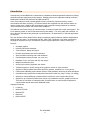
Getting Started
Login Screen
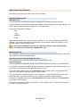
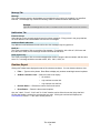
By default, BASview uses a flash Interface — providing a rich user experience. Its login appears below.
The default IP address of the BASview is 192.168.92.68, but yours may be set to a different address.
You will be prompted to login.
The default authentication strings are ...
o
Username: admin
o
Password: pass
At the top of the login dialog you can find ...
o
Firmware Version Number
o
BASview Serial Number
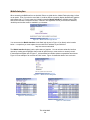
Figure 1 — Login Screen
At the bottom of the login dialog is an option to login with the Mobile Interface which uses HTML
and no flash — otherwise, you must proceed with the normal flash Interface.
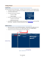
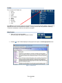
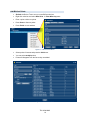
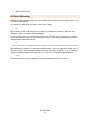
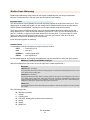
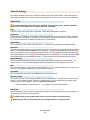
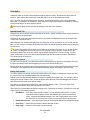
BASview Screen
After your first login, you see the BASview webpage — which defaults to the Info screen below.
The three basic screen elements are the Toolbar, Device Tree and the Working Area.
The Device Tree that you will build always starts with the Site icon.
Figure 2 — Main Screen
TD110500-0MC
5
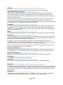
Toolbar
The 10 icons in the Toolbar are:
Home
Site Info
Logout
Users
User Groups
Admin
Alarms
Runtime
Tree View
Help
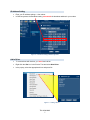
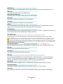
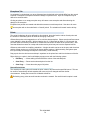
Figure 3 — Admin Options
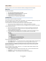
The Admin icon (the wrench symbol) is a drop-down where you can see logs and status, configure the IP
address, reboot the unit and update the firmware. If running 1.42d or later, any update file containing
".Firmware" somewhere in name can be used for the update.
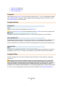
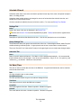
Help Screens
When you hover over any button,
you see a popup that explains the button function.
Figure 4 — Accessing Help Screens
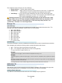
Pressing
on the Toolbar displays the help system and opens a context-appropriate screen.
Figure 5 — Help Screens
TD110500-0MC
6
IP Address Setting
Enter your IP address settings — then reboot.
In BACnet systems the Broadcast setting must match the broadcast address in your subnet.
Figure 6 — Broadcast Setting in BACnet Systems
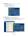
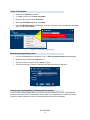
Add a Driver
To communicate with devices, you must load a driver.
Right-click the Site icon in the Device Tree and select New Driver.
In the popup, select the appropriate driver and press Ok.
Figure 7 — Adding a Driver
TD110500-0MC
7
Driver Configuration
Enter in your driver configuration.
For BACnet use a system-wide unique Device ID.
The standard BACnet port number is 47808.
Enter a label for the driver and press Finish.
Figure 8 — Driver Configuration
Add a Device to a Driver
In the Device Tree, right-click a driver and select New Device.
A Device Wizard appears so you can enter device parameters or, with BACnet, discover a device.
For BACnet, as shown below, press the Scan button to discover BACnet devices.
Press Finish on the next popup window.
Figure 9 — Adding a Device
TD110500-0MC
8
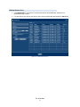
BACnet Device Scan
If the NetworkID is 0, the device is on the same network as the BASview; otherwise it is
accessed through a router.
For each device you want in your Device Tree, select it, add a label then press the Add button.
Figure 10 — BACnet Device Scan
TD110500-0MC
9
Add BACnet Points
Refresh the Device Tree to see your new BACnet devices.
Right-click a device and select New Point. A Point Wizard appears
Enter a point or discover points.
Press Scan to discover points.
Press Finish on next window.
Figure 11 — BACnet Point Wizard
Select points of interest and press the Add button.
You can select multiple points.
Points will disappear from the list as they are added.
Figure 12 — BACnet Point Scan
TD110500-0MC
10
Points To Be Written
All points are read-only by default.
To modify a point you must mark it writeable.
Right-click the point and select Properties.
When the Point Wizard appears, press Next.
Press the Modifications tab (if displayed), check the “Allow this point to be manually changed by
users” box and press Finish.
Figure 13 — Allow a Point to Be Changed
Manually Writing/Reading Points
Left-click a writeable point in the Device Tree. A Point Information/Control popup appears.
Modify its value and press the Apply button.
This can be used to simply view the status of a point.
The lock symbol can be used to view/modify the BACnet priorities for the point.
Figure 14 — Manually Modifying a Point
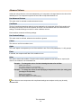
User Sessions Automatically Terminate after No Activity
A user session will automatically close if no user activity has occurred for one hour. Many BASview
functions entail edit screens. Please realise that any edits you are performing are volatile until saved.
Therefore, unsaved edits will be lost if not saved before the user session terminates.
TD110500-0MC
11
Advanced Colours
Advanced colours allow the colour and transparency of a component to change based on the value of the
attached point. The component may also be set to flash to help draw attention to it.
Use Advanced Colours
This option must be selected to enable advanced colours.
Conditions
The list of conditions determines what the current settings for the component will be. Each condition will
be tested, from the top of the list to the bottom of the list. The last condition that is true determines the
settings. The default settings are used if no other conditions are true.
Each condition contains the following settings:
Use Custom Settings
This option must be selected, otherwise the condition is ignored.
Colour
The colour to use if this condition is true.
Alpha
This is the "Alpha" or transparency to use if the condition is true. Zero is fully transparent, 1 is fully opaque.
Flash
If selected, the component will flash if this condition is true.
Value
The value to test for this condition. The point value must be greater than (not less than or equal to) this
value for the condition to be considered true.
Example — To change the colour of a label showing the state of an air filter:
Default - green (normal)
Point value is greater than 0 - red and flashing
(A digital value equates to 0 when OFF, 1 when ON.)
Example — To change the colour of text displaying a temperature to blue (too cold), green
(in range) or red (too hot):
Default - blue and flashing
Point value is greater than 65 - green
Point value is greater than 75 - red and flashing
Don't forget to save components with complicated settings as a template so they may be easily
recreated later.
TD110500-0MC
12
Alarm Wizard
An Alarm is invoked by right-clicking a device driver in the Device Tree. It monitors a set of user-defined
conditions and sends email notifications when the conditions are met. Once an alarm has been added to
the tree, left-click it to edit the conditions. See Alarm Editor for more information. Alarms are also stored
for later viewing using the Alarm Log.
Settings Tab
Label
Label is the name of the item as displayed in the Device Tree.
All items in the Device Tree are sorted alphabetically by label. Folders can be used to organize items.
Description
Description is optional text that describes the item. It can be any descriptive text or be left blank.
Group Settings Tab
These determine which user groups can see this item in the tree. Unchecking the default “Allow Everyone”
enables selecting individual groups. If a group cannot see an item, items under it are also unseen.
There are “Check All” and “Uncheck All” buttons in the upper-right corner to make major changes easier.
Advanced Tab
Name
Name is used for advanced features. If left blank, it will be assigned automatically. It is recommended
that the default value not be changed. It can be up to 48 characters. Only A–Z, a–z, 0–9, period (.) and
underscore (_) are allowed. Names are case sensitive.
Node ID
This internal reference ID of this node is read-only — and rarely needed by the user.
Alarm Log
Click this Toolbar button to view past alarm messages. Both active and optional clear messages are
stored in the log. Several options are available to limit the messages seen:
Filter — Type a word or phrase. Press “Enter” to activate the filter.
Month Selection — Select a month from the list to display only messages from that month.
All/Active/Clear — Choose to display all messages, only activation messages or only clear messages.
Refresh Button — Refresh the list of alarms from the server.
Reset Button — Reset all of the above search options.
Additionally, the “Time”, “Type” and “Message” headers may be clicked to sort the list by that field.
Clicking the header a second time will reverse the sort order. Clicking the alarm message itself will
display the Alarm Editor window if the users’ access permits it.
TD110500-0MC
13
Alarm Editor
Left-click an alarm icon in the tree to edit alarm conditions, messages and email recipients.
Status Tab
The status tab contains:
The current active/inactive status of the alarm.
The date and time of the last change of state of the alarm.
The last message generated by the alarm.
A refresh button to update the status on the screen.
A disable selection to completely disable the alarm.
Conditions Tab
This is where the alarm conditions are specified.
There are sub-tabs for active conditions and clear conditions. For backward compatibility, the logic used
for alarms is different depending on if clear conditions are present:
If clear conditions are not present (old-style alarms) the original logic still applies:
Alarm is active if active conditions are true for x minutes (x specified on active tab).
Alarm is inactive if active conditions are false for the same x minutes (x specified on active tab).
If clear conditions are present:
Alarm is active if the active conditions are true for x minutes (x specified on the active tab).
Alarm is cleared if the active conditions are not true, and the clear conditions are true for x
minutes (x specified on the clear tab).
Active conditions take precedence over clear conditions. If both are true, the alarm is active.
If neither active nor clear conditions are true, the alarm remains in its current state.
Example:
Conditions:
Active if temp > 78
Clear if temp < 74
Behaviour:
If temp goes up to 79, the alarm becomes active.
If temp goes down to 75, the alarm remains active.
If temp goes down to 73, the alarm is cleared.
There are two modes for the conditions:
All conditions are true — The alarm will be active or cleared if every condition evaluates to true.
Any condition is true — The alarm will be active or cleared if any condition evaluates to true.
To be considered active or cleared, the condition(s) must be true for at least the number of minutes
specified. If any/all of the conditions become false for the same number of minutes, the alarm will
become active or cleared.
Up to six conditions may be entered. Click the "+" or "X" buttons to add or delete conditions. Each
condition contains the following fields:
Point — Drag a point from the device tree and drop it here. Its value is what will be tested.
Comparison — This is the comparison that will be performed.
Comparison Value — This is what the point value will be compared with.
TD110500-0MC
14
The comparison value can be any one of the following:
Numerical Value — Type any valid numerical value.
Another Point — Drag a point from the tree to compare with its current value. For digital and
multi-state points, click the drop-down list to display the valid values.
Value Range — For the in/out of range comparisons, type the low value and the high value
separated by a comma (e.g.: 50,100). For the is/is not in list comparisons, type
a list of values separated by commas (e.g. 1,2,3,5,85,1000).
Floating point values (e.g. 72.5) are valid, but will not always give the desired results. What
displays on the screen as 72.5 may actually be 72.499854 because of the way computers round
numbers. Testing a point value for equality with 72.5 will most likely always be false. Use
"greater than", "less than" or a value range instead.
Messages Tab
Active Message
This is the message that is saved to the database and emailed when the alarm becomes active. The
following codes may be embedded in both the active or clear message:
= point address
= point description
@Hx = point high limit
@Nx = point name
@Lx = point label
@Sx = point status
@Ox = point low limit
@Ux = point units
@Ax
@Dx
(x = condition number)
Clear Message
This optional message is saved to the database and emailed when the alarm is cleared (becomes inactive).
Both messages may contain the following codes to embed information within the text:
@Vx
@Cx
— The value of the point (the point on the left-side)
— The comparison value (the point or value on the right side)
"x" in both codes is the condition number (1–6)
Example:
"Temperature is too high (@V1)." will be recorded as "Temperature is too high (77.4)".
Example:
"Temperature (@V1) is greater than setpoint (@C1)." will be recorded as "Temperature (76.3) is greater than setpoint
(74.5)."
"@" codes in the active message refer to the points and values on the "Active" tab. "@" codes in the clear message refer
to the points and values on the "Clear" tab.
For old-style alarms with no clear conditions, all @ codes refer to the points and values on the "Active" tab.
Notifications Tab
Email to Groups
Select the list of user groups that should receive this alarms messages. Every person in the group that
has an email address in the user database will receive both active and clear messages.
Additional Email Addresses
Any additional email addresses that should receive the messages may be typed here.
TD110500-0MC
15
Analog Point Wizard
Below are the settings for points with a point type of analog.
Analog Settings Tab
Engineering Units
The engineering units can be set to specify the units of measure or physical characteristics of the analog
value. Common engineering units would include Degrees F, Amps and Volts.
Type any text or select from a list of common units by clicking the down arrow to the right of the edit area.
Precision
Precision controls how the value is displayed. A value of 2 displays 2 digits to the right of the decimal
point (74.25). A value of 0 will truncate the decimal value and not display a decimal point at all (74).
Increment
Increment controls how the value can be changed by the user. It should normally be set to the increment
supported by the point in the device. A value of 1 allows the value to be changed in steps of 1 (74, 75,
76, etc.). A value of 0.1 allows steps of 0.1 (74.1, 74.2, 74.3, etc.)
For user modification, check "Allow this point to be manually changed by users" on the "Modifications" tab.
Modifications Tab
The modification settings are used to determine if the value of this point may be modified by users, and
how to handle or restrict the allowed values.
Allow this point to be manually changed by users
This checkbox must be selected for the point to be modifiable by the user.
Low Modify Limit
This is the lowest value to which the user will be allowed to modify the value. If left blank, any value valid
for the data type of the point will be allowed.
High Modify Limit
This is the highest value to which the user will be allowed to modify the value. If left blank, any value
valid for the data type of the point will be allowed.
In/Out Calculations
In and out calculations are optionally used to convert raw point values from a device in to more useable values.
For example, it is fairly common for Modbus devices to represent a temperature as the actual temperature *10.
In this case, 75.5 degrees would be read from the device as 755.
To this value treated properly, an In Calculation of @/10 would be used. The @ sign specifies where in
the calculation to insert the raw value from the device.
So in this example, it would calculate 755 / 10 for a result of 75.5. This calculated value is then used
everywhere else in the system instead of the 755, including on graphics, trends and alarms.
If the point is modifiable by the user, the Out Calculation should be the opposite of the In Calculation.
In this case it would be @*10. If the user then changes the value of the point to 76.2, the calculation 76.2
*10 would be executed and the value 762 sent to the device.
Several common calculation presets, including F to C and C to F conversions, are available by
clicking the down arrow to the right of the edit area.
Two points with the same address can have different calculations (such as a temperature in both F and C.
TD110500-0MC
16
BACnet MS/TP Device
This screen is used to configure access to a single device on a BACnet/MS/TP network.
Settings Tab
Label
Label is the name of the item as displayed in the Device Tree.
All items in the Device Tree are sorted alphabetically by label. Folders can be used to organize items.
MAC Address
The MAC address of the device must be 0–127 and not match any other attached MS/TP device.
Device ID
The BACnet device ID of the device must be a unique number of 0–4,194,303.
Max. APDU Size
The Maximum APDU size supported by the unit defaults to 480. If problems arise, try a lower value.
Write Priority
The default BACnet priority to use when writing to points on this device. Setting this to zero forces property
writes to the device to use priority "None". Points can use the "@x" syntax to override this setting.
Group Settings Tab
These determine which user groups can see this item in the tree. Unchecking the default “Allow Everyone”
enables selecting individual groups. If a group cannot see an item, items under it are also unseen.
There are “Check All” and “Uncheck All” buttons in the upper-right corner to make major changes easier.
Advanced Tab
Name
Name is used for advanced features. If left blank, it will be assigned automatically. It is recommended
that the default value not be changed. It can be up to 48 characters. Only A–Z, a–z, 0–9, period (.) and
underscore (_) are allowed. Names are case sensitive.
Node ID
This internal reference ID of this node is read-only — and rarely needed by the user.
Disable communication with this device
Check this box to prevent communications with this device. Uncheck for normal operation.
Template Button
With this you can select a saved template and apply its properties to the new device.
Scan Button
With this you can scan the BACnet internetwork to confirm that the new device properties are appropriate.
TD110500-0MC
17
BACnet MS/TP Driver
This screen is used to configure access to a BACnet MS/TP network. This driver is only used when
connecting the BASview MS/TP module (BASV-MSTP) to the BASview. You can also communicate with
MS/TP networks through a BACnet router (BASRT-B) — in which case you would communicate to these
devices through the BASview BACnet/IP driver.
Settings Tab
Label
Label is the name of the item as displayed in the Device Tree.
All items in the Device Tree are sorted alphabetically by label. Folders can be used to organize items.
Description
Description is optional text that describes the item. It can be any descriptive text or be left blank.
Device ID
This is the device ID to use for the BASview unit itself. It must be unique for the entire BACnet network.
MAC Address
This is the MAC address or node ID for the BASview unit on the MS/TP network. It must be unique for
the MS/TP network.
Baud Rate
This is the baud rate used in the MS/TP network. The standard BACnet baud rates of 9600, 19200,
38400 and 76800 are supported.
Max. Master
This is the highest MAC address used on the network. Setting this too low may cause devices with
higher MAC addresses to not function properly. Setting it too high is inefficient, but will not otherwise be
harmful. If unknown, use 127.
Max. Info Frames
The number of frames or packets of data the BASview should be allowed to transmit each time it is has
control of the network (when it has the MS/TP token). The default of 1 is recommended.
APDU Timeout
This is the APDU timeout, in milliseconds to use for devices on the BACnet network. It should be set to
the highest APDU timeout used by any device on the network. Normally, it should be left at the default of
3,000 (3 seconds).
Group Settings Tab
These determine which user groups can see this item in the tree. Unchecking the default “Allow Everyone”
enables selecting individual groups. If a group cannot see an item, items under it are also unseen.
There are “Check All” and “Uncheck All” buttons in the upper-right corner to make major changes easier.
Advanced Tab
Name
Name is used for advanced features. If left blank, it will be assigned automatically. It is recommended
that the default value not be changed. It can be up to 48 characters. Only A–Z, a–z, 0–9, period (.) and
underscore (_) are allowed. Names are case sensitive.
TD110500-0MC
18
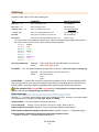
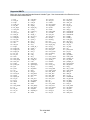
BACnet Point Addressing
BACnet point addressing is very simple for standard BACnet I/O points. Extended addressing is also
available to access non-I/O or proprietary points.
Address Format
A valid address must have at least a point type and a point number:
AV3
— Analog Value #3
BO14 — Binary Output #14
MSI205 — Multi-State Input #205
The list of supported point types includes:
AI
AO
AV
AVG
BI
BO
BV
CAL
CMD
DEV
— Analog Input
— Analog Output
— Analog Value
— Averaging Object
— Binary Input
— Binary Output
— Binary Value
— Calendar Object
— Command Object
— Device Object
EE
FL
GRP
LP
MSI
MSO
MSV
NC
PRG
SCH
TL
— Event Enrolment Object
— File Object
— Group Object
— Loop Object
— Multi-State Input
— Multi-State Output
— Multi-State Value
— Notification Class Object
— Program Object
— Schedule Object
— Trend Log Object
Please note that even though properties of non-I/O objects can be read and written, there is currently no
support for editing an object as a whole object. For example, a single property of a schedule object may
be changed, but editing the dates and times of a schedule in a grid is not supported.
Other Standard and Proprietary Objects
For standard object types not listed above or for proprietary points, the address may be specified as
objectType:InstanceID.
Example:
22032:89 — Proprietary object type #22032, instance #89.
Property ID
If not specified, property #85 (present value) is assumed. A different property ID may be specified with a
comma, followed by the property ID:
Examples:
AV32,81 — Analog Value 32, property ID 81 (Out of Service flag)
22032:89,72 — Proprietary object type #22032, instance #89, property 112 (status flags)
TD110500-0MC
19
Data Type
The data type used for the objects listed above with property #85 (present value) is automatically known
and used. If a property other than present value is used, or for any property of a proprietary object the
default data type is "String". This will allow the value of the property to be viewed but will probably not be
sufficient to write a new value to the property. Note that only NULL, boolean, character string and all of
the numeric data types currently support writing.
To use a different data type, it must be specified immediately following the property ID with a comma and
a data type specifier:
Examples:
AV32,81,BOOL — Analog Value 32, property ID 81 (Out of Service flag), treat the value as a boolean.
22032:89,72,INT — Proprietary object type #22032, instance #89, property 112 (status flags), treat the value as an integer.
The list of supported point types includes:
NULL
BOOL
UINT
INT
REAL
DBL
OCT
STR
—
—
—
—
—
—
—
—
A NULL or empty value
Boolean off/on, 0/1, inactive/active, etc.
Unsigned integer
Signed integer
A Real" or floating point value
A double precision floating point value
Octet String (binary data)
Character string (standard ASCII characters)
BITS
ENUM
DATE
TIME
OBJ
RES1
RES2
RES3
—
—
—
—
—
—
—
—
Bit String
Enumeration
Date
Time
Unspecified object type
Currently reserved by BACnet
Currently reserved by BACnet
Currently reserved by BACnet
Array Index
For array type objects, an array index may be specified after the data type with a comma, followed by the
array index to read:
Example:
22032:89,72,INT,56 — Proprietary object type #22032, instance #89, property 112 (status flags), treat the value as an
integer, array index 56.
Note: All parameters of an address must be specified in the order listed above. For example, the
array index may not be specified unless the property ID and data type are also specified first.
TD110500-0MC
20
BACnet/IP Device
This screen is used to configure access to a single device on a BACnet/IP network.
Settings Tab
Label
Label is the name of the item as displayed in the Device Tree.
All items in the Device Tree are sorted alphabetically by label. Folders can be used to organize items.
Address
The IP address of the device or router (Example: 192.168.0.60). Do not include the UDP port.
Device ID
The BACnet device ID of the device must be a unique number or 0–4,194,303.
Max. APDU Size
The Maximum APDU size supported by the unit defaults to 480. If problems arise, try a lower value.
Network #
The BACnet network number (0–65,535) of the unit is only needed for devices behind routers.
Destination Address
The destination address is only needed if the device is behind a router. Usually this is its MS/TP address.
Write Priority
The default BACnet priority to use when writing to points on this device. Setting this to zero forces property
writes to the device to use priority "None". Points can use the "@x" syntax to override this setting.
Group Settings Tab
These determine which user groups can see this item in the tree. Unchecking the default “Allow Everyone”
enables selecting individual groups. If a group cannot see an item, items under it are also unseen.
There are “Check All” and “Uncheck All” buttons in the upper-right corner to make major changes easier.
Advanced Tab
Name
Name is used for advanced features. If left blank, it will be assigned automatically. It is recommended
that the default value not be changed. It can be up to 48 characters. Only A–Z, a–z, 0–9, period (.) and
underscore (_) are allowed. Names are case sensitive.
Node ID
This internal reference ID of this node is read-only — and rarely needed by the user.
Disable communication with this device
Check this box to prevent communications with this device. Uncheck for normal operation.
Template Button
With this you can select a saved template and apply its properties to the new device.
Scan Button
With this you can scan the BACnet internetwork to confirm that the new device properties are appropriate.
TD110500-0MC
21
BACnet/IP Driver
This screen is used to configure access to a BACnet/IP network. Other BACnet networks, such as MSTP
may also be accessed with this driver through a 3rd party router.
Settings Tab
Label
Label is the name of the item as displayed in the Device Tree.
All items in the Device Tree are sorted alphabetically by label. Folders can be used to organize items.
Description
Description is optional text that describes the item. It can be any descriptive text or be left blank.
Device ID
This is the device ID to use for the BASview unit itself. It must be unique for the entire BACnet network.
UDP Port
This is the UDP port the BACnet network is using. The default is 47808 (BAC0).
APDU Timeout
This is the APDU timeout, in milliseconds to use for devices on the BACnet network. It should be set to
the highest APDU timeout used by any device on the network. Normally, it should be left at the default of
3,000 (3 seconds).
Network Delay
The network delay can be used to throttle traffic on the BACnet/IP network.
The value specified here is the number of milliseconds to wait between network transmissions on the
BACnet/IP network. It may be set higher on busy networks or for slower devices causing read errors. It
may be set lower for faster point updates. Except in extreme conditions, it should be set to 100 or lower.
Group Settings Tab
These determine which user groups can see this item in the tree. Unchecking the default “Allow Everyone”
enables selecting individual groups. If a group cannot see an item, items under it are also unseen.
There are “Check All” and “Uncheck All” buttons in the upper-right corner to make major changes easier.
Advanced Tab
Name
Name is used for advanced features. If left blank, it will be assigned automatically. It is recommended
that the default value not be changed. It can be up to 48 characters. Only A–Z, a–z, 0–9, period (.) and
underscore (_) are allowed. Names are case sensitive.
TD110500-0MC
22
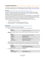
Calculations
A calculation reads points from one or more devices and performs a calculation on them, such as
average, minimum or maximum. Custom calculations can also be used. Calculations may be used on
graphics, trends, alarms and other calculations just like physical points.
Add a calculation in the Device Tree by right-clicking the desired node — it can be a site, driver or
device. The Calculation Wizard then appears. After the calculation has been added to the tree, left-click
it to edit it. See Calculation Editor for more information.
Calculation Wizard
Settings Tab
Label
Label is the name of the item as displayed in the Device Tree.
All items in the Device Tree are sorted alphabetically by label. Folders can be used to organize items.
Description
Description is optional text that describes the item. It can be any descriptive text or be left blank.
Group Settings Tab
These determine which user groups can see this item in the tree. Unchecking the default “Allow Everyone”
enables selecting individual groups. If a group cannot see an item, items under it are also unseen.
There are “Check All” and “Uncheck All” buttons in the upper-right corner to make major changes easier.
Advanced Tab
Name
If left blank, it will be assigned automatically. It is recommended that the default value not be changed. It
can be up to 48 characters. Only A–Z, A–Z, 0–9, period (.) and underscore (_) are allowed. Names are
case sensitive.
TD110500-0MC
23
Calculation Editor
A calculation is edited by left-clinking its node. Points must be dragged from the device tree and dropped
in the points list. Drop every point that will be part of the calculation. The order of the points is generally
not important unless a custom function is used.
Function
Select the function to perform on the points in the point list. For example, to average three temperatures,
drag the three temperature points to the point list and select "Average".
Custom functions are also supported by selecting "Custom" and entering a calculation in the "Postfunction Calculation" below.
Post-function Calculation
The post-function calculation is used to perform an additional calculation on the result of the function, or
to specify a custom function.
Example: To have this Calculation point equal the average of three temperatures, but converted from Fahrenheit to
Celsius, add the three points to the list, select "Average" and enter the following in the post-function calculation:
(@R-32)/1.8
The result of the calculation function selected above (the average temperature in this example) will be
inserted in to the post-function calculation where the @R code is located.
To use a completely custom function, select "Custom" as the function and then enter a post-function
calculation with @Vx codes where the point values from the list should appear. @V1 is the value of the
first point in the list, @V2 the second point, etc.
Example: To get the sum total of three points and subtract 100 from it, enter the following in the post-function calculation:
(@V1+@V2+@V3)-100
Several built-in sub-functions are available to call from within the post-function calculation:
min
max
CtoF
FtoC
—
—
—
—
Returns the minimum of a list of values: min(@V1,@V2,@V3).
Returns the maximum of a list of values: max(@V1,@V2,@V3).
Convert a value from Celsius to Fahrenheit: CtoF(@V1)
Convert a value from Fahrenheit to Celsius: FtoC(@V1)
Example: To get the lowest of three temperatures and then convert it from Celsius to Fahrenheit, add the three points to
the list, select "Custom" and enter the following in the post-function calculation:
CtoF(min(@V1,@V2,@V3))
Refresh Button
The refresh button will update the value and status shown on the screen. If changes have been made,
they must first be saved by clicking the "Apply" button.
Units
This is the engineering units to display for this Calculation when used on graphics.
Precision
This is the number of digits to the right of the decimal point to display for this Calculation when used
on graphics.
TD110500-0MC
24
Control Points
A Control Point, usually referred to as just a "point", is any input, output, variable or property on a device
that a value can be read from, and possibly allows a new value to be written to it.
At least one point is required for the unit to do anything useful. Most systems will have dozens or
hundreds of points. For point types see the Analog Point Wizard, Digital Point Wizard, Multi-State Point
Wizard, Date/Time Point Wizard and String Point Wizard.
Settings Tab
Label
Label is the name of the item as displayed in the Device Tree.
All items in the Device Tree are sorted alphabetically by label. Folders can be used to organize items.
Address
The address is the name, number or combination of the two that specifies how to access and interpret
this point. Addressing is different for different types of devices (LonWorks, Modbus, etc.) See Point
Addressing for information on how to specify the address.
Virtual Point
Check this box to declare this point as "virtual". Virtual points hold a value but are not read or written to a
device so they do not require an address. Their value is maintained internally and can be used anywhere
a normal point can be used. They are normally used with program or calculation objects for smart
setpoint logic or to hold user specified values.
Description
Description is optional text that describes the item. It can be any descriptive text or be left blank.
Point Type
The Point Type specifies how the value should be treated and displayed once it has been read from the device.
The available point types are:
Analog
— Any numeric value. Digital values are converted to 0 for OFF and 1 for ON.
Digital
Multi-State — One of a limited set of numeric values such as 1 through 4, or -2 through 15.
String
— The value is a string of ASCII characters.
DateTime
— The value is a packed binary date, time or combined date/time value.
— The value is treated as ON or OFF. Any non-zero value is considered ON.
Although the point type should usually be set to match the actual type of point, it is sometimes useful
to use a different setting. For example, an analog input could be set to a point type of Digital so that any
value other than 0 would be displayed as ON or Active.
Point Class
The Point Class is currently used only for informational purposes and has no real effect on how the value
will be treated or displayed. It may be used for more in a future version so it is recommended that it
always be set to the proper value.
The available point classes are:
Input
— The point is a physical input of any type.
Output
— The point is a physical output of any type.
Variable — The point is a logical device point — such as a setpoint, programming variable or flag.
Object
— The point is an object or other logical data structure.
TD110500-0MC
25
Group Settings Tab
These determine which user groups can see this item in the tree. Unchecking the default “Allow Everyone”
enables selecting individual groups. If a group cannot see an item, items under it are also unseen.
There are “Check All” and “Uncheck All” buttons in the upper-right corner to make major changes easier.
Advanced Tab
Name
Name is used for advanced features. If left blank, it will be assigned automatically. It is recommended
that the default value not be changed. It can be up to 48 characters. Only A–Z, a–z, 0–9, period (.) and
underscore (_) are allowed. Names are case sensitive.
Date/Time Point Wizard
Below are the settings for points with a point type of DateTime.
Date/Time Settings Tab
Allow this point to be manually changed by users
This checkbox must be selected for the point to be modifiable by the user.
Devices
A device is any physical device, panel or I/O unit in the system.
Supported devices include:
LonWorks Device
Modbus Serial Device
Modbus/TCP Device
BACnet/IP Device
TD110500-0MC
26
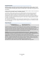
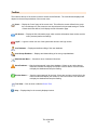
Device Tree
The device tree appears on the left side of the main window. It displays all interactive items in the
system. Each type of item is represented by one of the following icons:
Alarms — Monitors specified conditions and generates an alarm message and optional email alerts.
Calculations — Reads the value of one or more points and performs a calculation on them — for
example, averaging several temperatures.
Devices — Any physical device, panel or I/O unit in the system.
Drivers — A physical network or logical grouping of devices based on the protocol they use — for
example, an entire LonWorks network is a single driver.
Folders — Used to help organize other items. Folders may contain other folders.
Graphics — Used to display information from the system and to control equipment.
Links — Used to access other units, web pages or other web content.
Points — Any physical or logical control point on a device. Inputs, outputs, setpoints and variables
on a device are all considered "points".
Programs — Allows simple programs to be written to control setpoints, outputs and other points.
Runtimes — Monitors specified conditions and accumulates the amount of time the conditions are
true, and generates a message and optional email alerts when a limit is reached.
Schedules — Allows for control of several points based on the time of day.
Site — The root item from which all other items branch.
Trends — Automatically records point values at specified intervals to allow for later viewing.
Navigating the Device Tree
Drivers, devices and folders may contain other items. Click the item to open it and display any sub-items.
Click again to close the item and hide the sub-items.
Clicking any other item will display a viewing/editing screen for the item. Click a graphic to view it, click a
point to display and control the value, etc.
Right-click any item and select "Collapse" or "Collapse All" to close an open folder or all open folders.
Editing the Device Tree
Right-click any item(s) and select "Delete Item(s)" to remove it or them from the tree.
Deleting an item will also delete all sub-items beneath it in the tree.
Clicking and dragging an item allows it to be moved. Note that there are several restrictions on where
items may be dropped. Generally, items under a device may only be dropped on a folder under that
same device, or on the device item itself. Devices under a driver may only be dropped on folders under
the same driver, or on the driver itself.
If an item needs to be moved outside of these restrictions, right-click the item, save it as a template,
delete it and then recreate it from the template at the new location. Note that the points attached to items
using this method may need to be re-attached
Multiple items may be moved or deleted at the same time. Hold down the Ctrl key and click an item to
select multiple items. Hold down the Shift key and click an item to select all items from the highlighted
item to the newly clicked item. Note that the restrictions explained above still apply when moving multiple items.
TD110500-0MC
27
Adding Items
Right-clicking an existing item in the tree will display a popup menu with options to create new items. The
items available will depend on the type of item clicked.
Editing Items
To edit any item, right-click it and select "Properties". An editor screen specific to that item will appear.
Save as Template
Right-click any item and select "Save as Template" to save the item — and all sub-items beneath it — as
a single template. This template may later be restored to clone the items. See
Templates for more.
Digital Point Wizard
Below are the settings for points with a point type of digital.
Digital Settings Tab
Allow this point to be manually changed by users
This checkbox must be selected for the point to be modifiable by the user.
Digital Text
The digital text setting allows the point to be displayed as something other than ON or OFF.
Several preset pairs of digital text labels are available in the drop-down box above the edit area. Any
custom labels may also be used by typing directly in the editing area.
The format for digital text labels is:
0:Normal
1:Alarm
The 0 label (Normal) will be displayed when the point is OFF (or zero). The 1 label (Alarm) is used when
the point is ON (or any non-zero value). There should be no extra spaces anywhere except in the text
label itself.
TD110500-0MC
28
Drivers
A driver is a physical network or logical grouping of devices based on the protocol they use. For example,
an entire LonWorks network is a single driver.
Supported devices include:
LonWorks Driver
Modbus Serial Driver
Modbus/TCP Driver
BACnet/IP Driver
BACnet MS/TP Device
This screen is used to configure access to a single device on a BACnet/MS/TP network.
Settings Tab
Label
Label is the name of the item as displayed in the Device Tree.
All items in the Device Tree are sorted alphabetically by label. Folders can be used to organize items.
MAC Address
The MAC address of the device must be 0–127 and not match any other attached MS/TP device.
Device ID
The BACnet device ID of the device must be a unique number of 0–4,194,303.
Max. APDU Size
The Maximum APDU size supported by the unit defaults to 480. If problems arise, try a lower value.
Write Priority
The default BACnet priority to use when writing to points on this device. Setting this to zero forces property
writes to the device to use priority "None". Points can use the "@x" syntax to override this setting.
Group Settings Tab
These determine which user groups can see this item in the tree. Unchecking the default “Allow Everyone”
enables selecting individual groups. If a group cannot see an item, items under it are also unseen.
There are “Check All” and “Uncheck All” buttons in the upper-right corner to make major changes easier.
Advanced Tab
Name
Name is used for advanced features. If left blank, it will be assigned automatically. It is recommended
that the default value not be changed. It can be up to 48 characters. Only A–Z, a–z, 0–9, period (.) and
underscore (_) are allowed. Names are case sensitive.
Node ID
This internal reference ID of this node is read-only — and rarely needed by the user.
Disable communication with this device
Check this box to prevent communications with this device. Uncheck for normal operation.
Template Button
With this you can select a saved template and apply its properties to the new device.
Scan Button
TD110500-0MC
29
With this you can scan the BACnet internetwork to confirm that the new device properties are appropriate.
TD110500-0MC
30
BACnet MS/TP Driver
ESI Point Addressing
Addresses for ESI points are actually just the commands used to read and write the desired data — with
an optional format specifier.
For example, the address for the "Name" of the device is simply:
N
When the point is read, it will send out the command "N?" and wait for a response. When the user
changes the name, it will send out "NTheNewName".
For some points, such as the current position of the motor, it needs to use one command (r) to read the
position and a different command (m) to change the position. In this case, the address should use the
readCommand;writeCommand format:
r;m
(The semi-colon here is a command separator and has nothing to do with the semi-colon required at the end of ESI commands.)
With this address, it issues an "r?" command to read the position. If the user changes the position to 50, it
will send out "m50". But this presents a problem if the user changes the position to 6. The "m" command
requires 2 characters for the position (m06, not m6). In this case, use the optional format specifier:
r;m;00
This will format the command to always be 2 characters, padded on the left with zeroes.
TD110500-0MC
31
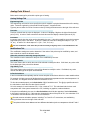
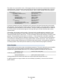
Folders
Folders are used to organize tree items. They are typically used to contain a single type of item, such as
all points on a device, all schedules, or all devices in a specific area.
Any type of item may be placed inside a folder, including other folders. On a system with many items it is
important to keep them organized for ease of use. One organizational system might be something like:
Figure 15 — Folders in the Device Tree
But there are no built-in limitations on how items are organized.
Settings Tab
Label
Label is the name of the item as displayed in the Device Tree.
All items in the Device Tree are sorted alphabetically by label.
Group Settings Tab
These determine which user groups can see this item in the tree. Unchecking the default “Allow Everyone”
enables selecting individual groups. If a group cannot see an item, items under it are also unseen.
There are “Check All” and “Uncheck All” buttons in the upper-right corner to make major changes easier.
Advanced Tab
Name
Name is used for advanced features. If left blank, it will be assigned automatically. It is recommended
that the default value not be changed. It can be up to 48 characters. Only A–Z, a–z, 0–9, period (.) and
underscore (_) are allowed. Names are case sensitive.
TD110500-0MC
32
Graphics Wizard
Graphics allow for visual representations of areas, floors, buildings or hardware systems. The available
components include text labels, checkboxes, LEDs, seven-segment displays, etc. GIF Animations are
also supported. You can display a Graphics Wizard by right-clicking on major nodes in the Device Tree.
The major modes are Site, Driver and Device.
Settings Tab
Label
Label is the name of the item as displayed in the Device Tree.
All items in the Device Tree are sorted alphabetically by label.
There are two basic types of graphic screens:
Unique Graphic
A unique graphic is the most common and simple type of graphic. Each unique graphic represents exactly
one area, floor or system. Changes made to a unique graphic do not affect any other graphic.
A different unique graphic would be used for each unique area or system, or even for very similar but not
identical floors of a building, VAV systems or rooftop systems.
Shared Graphic
A shared graphic would be used only for virtually identical VAV systems, floors or areas. Shared graphics
use a single data file that — when changed — affect all graphics that use the shared file.
The main advantage of a shared graphic is that one graphic can be designed and reused for an unlimited
number of identical areas. When a change needs to be made, all graphics that use the shared file are
updated automatically.
Shared graphics do allow for different text labels on each instance, but no other changes are
allowed between instances. There is no way to show components on one instance but not on
others. Consider using unique graphics if this is needed.
Shared Data File
This is the shared data file that should be used for this graphic. Click the "Select" button and select or
create a new data file to set this field.
Group Settings Tab
These determine which user groups can see this item in the tree. Unchecking the default “Allow Everyone”
enables selecting individual groups. If a group cannot see an item, items under it are also unseen.
There are “Check All” and “Uncheck All” buttons in the upper-right corner to make major changes easier.
Advanced Tab
Name
Name is used for advanced features. If left blank, it will be assigned automatically. It is recommended
that the default value not be changed. It can be up to 48 characters. Only A–Z, a–z, 0–9, period (.) and
underscore (_) are allowed. Names are case sensitive.
Node ID
This internal reference ID of this node is read-only — and rarely needed by the user.
TD110500-0MC
33
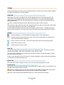
Graphic Components
The
button displays the Component Templates dialog of two sections: a folder / file tree on the left
and a label / preview section on the right. The three component categories are:
Display Only
Display and Control
Miscellaneous Components
Display Only Components
These components display the state or value of points — but do not allow changing the value.
LED
This round LED (light emitting diode) has the following properties:
Colour — This sets the ON colour. The OFF colour is automatically a darker shade of the ON colour.
Flash when On — Select this to make the LED flash when the point value is ON (non-zero).
LED Display
These 7-segment digits display point values (blanks if no data present). The properties are:
Colour — This sets the colour of the digits in the display.
Background Colour — This sets the background colour behind the digits.
Number of Digits — This includes all digits and the decimal point itself (e.g., 74.25 = 5 digits).
Show Units — Selecting this option displays engineering units to the right of the value.
Animation
BASview animations are GIF files that show the first image when not running. A GIF animation can be
created with most graphic editors. Click the Select button to upload / choose a GIF animation.
Off Animation — (Optional) A GIF to run when the "Animate When..." condition is false. No other
control of this animation is possible. Click the Select button to upload and / or choose a GIF animation.
Animate when… — When the animation runs is determined by one of these options:
Always — Always run, regardless of the point value (even if no point is attached).
Point is ON (non-zero) — Run when the point is ON (any non-zero value).
Point is OFF (equals zero) — Run when the point is OFF (value at zero).
Point value is less than minimum — Run when the point value is less than the minimum.
Point value is greater than maximum — Run when the point value is greater than maximum.
Point value is in min/max range — Run when the point value equals or is between either limit.
Point value is out of min/max range — Run when the point value is outside the limit range.
<Convert value to a single frame relative to min/max> — (Commonly used to show damper or valve
positions.) Instead of running, just one frame displays — as determined by point value in the
min/max range. For example, if you assign a 10–frame animation a min/max range of 0–100, then
a point value of 0–9 displays frame #0 (the first frame), a value of 10–19 displays frame #1, etc.
TD110500-0MC
34
Minimum — The minimum point value used to control animations. See "Animate when…" above.
Maximum — The maximum point value used to control animations. See "Animate when…" above.
Stretch to Fit — Allows the animation to stretch or shrink, otherwise it displays at default size.
Maintain Aspect Ratio — This preserves the width / height ratio as the animation is resized.
Smoothing — This softens resized animation edges. (Takes more memory, so use cautiously.)
Fan Animation
This simple fan symbol animates when the attached point value is ON or non-zero. It has one property:
Blade Colour — This is the colour of the fan blades.
Light Fixture
This animation is ON whenever the attached point value is ON (non-zero). Its properties are:
Lighting Colour — This sets the colour of the light.
Fixture Colour — This sets the colour of the fixture.
Display and Control Components
These components display the state or value of a point and allow changing the value.
Check Box
This digital ON / OFF control works as in many programs and web sites. Its options are:
Background Colour — This is the colour of the background area behind the checkbox.
Background Alpha — Sets the background transparency: 0 is fully transparent, 1 is fully opaque.
Text Colour — This is the colour of the text in the checkbox.
Caption — This is the text displayed in the checkbox.
Combo Box
This displays the current point value and allows selection multi-state or digital values. Its options are:
Background Colour — This is the colour of the background area behind the combo box.
Background Alpha — Sets the background transparency: 0 is fully transparent, 1 is fully opaque.
Text Colour — This text colour is based on the point’s multi-state or digital text properties.
Radio Group
This displays all possible multi-state or digital point values and allows one to be selected. Its options are:
Background Colour — This is the colour of the background area behind the radio group.
Background Alpha — Sets the background transparency: 0 is fully transparent, 1 is fully opaque.
Text Colour — This text colour is based on the point’s multi-state or digital text properties.
Spinner
This displays the current point value and has up / down arrows to raise or lower the value. The value
limits are set in the "Modifications" tab of the point’s property screen. This component’s options are:
Background Colour — This is the colour of the background area behind the text.
Text Colour — This is the colour of the text in the spinner.
TD110500-0MC
35
Text Label
This can display the value, status or engineering units of a point. It can be used without a point to display
titles or information and may also link to other screens or even web sites.
Text Tab
Text — The displayed text can include codes to embed point information. Examples:
The code "Temperature = @V" displays Temperature = 74.3.
"The @L is @V (@U)" displays The Outdoor Temperature is 81.4 (Deg.F).
Text can include HTML tags. See HTML Help for more information.
The available codes are:
With shared graphics the @substitution codes may also be used.
Text Size — This is the size of the text, in pixels, before any scaling of the screen.
Text Colour — This is the colour the text.
Advanced Colours… — Options for different colours, transparencies, flashing text, based on point value.
Alignment — This aligns text horizontally within the component. The choices are left, centre or right.
Background Tab
Background Colour — This is the colour of the background area behind the text.
Background Alpha — Sets the background transparency: 0 is fully transparent, 1 is fully opaque.
Border Tab
Border Colour — This is the colour of the solid border surrounding the text.
Border Size — This is the size of the text border. For no border, set this to zero.
Link Tab
Screen/URL — A screen or web page displays when clicked. If left blank but a point is attached, the
point info / modify screen appears. To set a screen link, drag an item from the tree and drop it on the
link edit area. To web page link, type or paste (Ctrl-V) the address in the edit area.
A URL must be complete, including 'http://'.
Underline Text — If desired, this will underline the text to resemble a typical web page link.
TD110500-0MC
36
Miscellaneous Components
These components do not require points.
Gradient
This can be a background to give the graphic a less "flat" look, or a box to visually distinguish
components. (Right-click the gradient and "Send to back" to avoid hiding other components.)
Start Colour — This is the starting colour of the gradient.
End Colour — This is the ending colour of the gradient.
The start and end colour should usually be fairly close, for example, black and grey. Large or wild
colour changes (purple to yellow) can be very distracting to many people and make the whole system
look less professional.
Gradient Angle — This is the angle of the gradient. It can be set to any valid angle (0-360).
Border Colour — This is the colour of the solid border surrounding the gradient.
Border Size — This is the size of the solid border surrounding the gradient. Set this to zero for no
border.
Alpha — This is the "Alpha" or transparency of the entire gradient and border. Zero is fully
transparent, 1 is fully opaque.
Image
Image — Image is a standard JPG, GIF or PNG image file. Click the Select button to upload and/or
choose an image file.
Windows Bitmap (BMP) files are not supported. A BMP file can be loaded in to almost any image
editor and saved as a JPG, GIF or PNG file.
Stretch to Fit — If selected, this option allows the image to be stretched or shrunk. If not selected,
the image will always be displayed at its default size.
Maintain Aspect Ratio — If selected, this option keeps the width to height ratio the same as it is
stretched. If not selected, the image can be distorted as it is stretched.
Smoothing — This option will smooth a stretched image so it appears less jagged. It does hurt
performance, so it should not be used with a large number of images, or with very big images.
Link Button
The Link Button is quick and simple way to add links to other graphics, schedules, trends, points, alarms, etc.
Background Colour — This is the colour of the background area.
Background Alpha — This is the "Alpha" or transparency of the link button. Zero is fully transparent,
1 is fully opaque.
Text Colour — This is the colour of the text in the link button.
Caption — This is the text displayed in the link button. If left blank, the label of the item the button
links to will be used.
Close Graphic — If selected, this option will close the current graphic when opening the new item.
TD110500-0MC
37
Graphic Screen Editing
Left-click a graphic icon in the tree to add, delete or change graphic component properties. Components
(visual items on a graphic screen) include text labels, check boxes, animations, etc.
Adding Components
To add new components to the graphic, drag an item from the device tree and drop it on the graphic. A
component selection dialog will be displayed allowing selection of a component to use for the item.
Alternately, click the
button to display the Components dialog that allows adding components that are
not attached to device tree items.
Hold down the Ctrl key as you drop an item on a graphic to automatically use the last component selected.
Selecting Components
Click a component to select it. To select multiple components, hold down the Shift key while clicking — or
draw a box around the desired components by left-clicking-and-holding on the graphic background while
dragging the mouse to form a box. All components that touch or are within the box will be selected.
Positioning Components
With one or more components selected, left-click and hold on a selected component — then drag the
component(s) anywhere on the graphic screen. For only vertical movement while dragging, hold the Shift
key down. For only horizontal movement, hold the Ctrl key down.
Editing Components
Right-click a component and select "Properties" to edit the settings of a component. Multiple components
may be edited at the same time if they are all the same type. Note that this will change all of the settings
of all of the selected components, not just the settings that are changed. Click the "Apply" button to apply
and see changes. Click the "Close" button when done making changes. To change the point attached to
a component, drag the new point from the device tree and drop it on the component.
Pop-up Menu
Right-click a component to display a pop-up menu of options which include:
Properties… — Display the Properties dialog for the selected component.
Align… — Display the Align dialog to align multiple components.
Size… — Display the Size dialog to size multiple components.
Scale… — Display the Scale dialog to scale multiple components.
Delete Item(s) — Delete the selected components.
Cut Items(s) — Copy the selected components to the clipboard and delete them from this graphic.
Copy Item(s) — Copy the selected components to the clipboard.
Paste Item(s) — Paste components from the clipboard onto this graphic.
Bring to Front — Reorder selected components so they appear above other components.
Send to Back — Reorder selected components so they so they appear behind other components.
Save Component — Save the selected component and its settings as a template for easy re-use.
Components may be copied and pasted between graphics but must be re-attached if the graphics
are under different devices or if points with the same names do not exist on the second device.
TD110500-0MC
38
Toolbar Buttons
View Mode — Click to change from Edit mode to View mode.
Save Graphic — Click to save changes made to this graphic.
Edit Properties — Click to edit the Graphic Properties dialog — which includes background options.
Align Components — Click to display the Align dialog — or the down arrow for quick options.
Size Components — Click to display the Size dialog — or the down arrow for quick options.
Cut to Clipboard — Click to remove selected components from this graphic to the clipboard.
Copy to Clipboard — Click to copy selected components to the clipboard.
Paste from Clipboard — Click to paste components from the clipboard to this graphic.
Delete Components — Click to delete selected components.
Scale Graphic — Click to automatically scale the graphic to the current screen size. Click the down
arrow to select a different scale.
Auto-label Components — Click to automatically add text labels to all selected components. Label
style and position can be changed via the pull-down menu to the right of this icon.
View Components — Click to view the list of components. Then select one to place on this graphic.
Graphic Screen Viewing
Graphic screens are used to display information from the system and to control equipment. Each graphic
is custom designed for a site, so specific help for this graphic is not available.
Toolbar
Edit Graphic — Click to enter edit mode. Edit mode allows adding, deleting and modifying graphic
components. Edit mode is only available to users with permissions set to allow graphic editing.
Scale Graphic — Click the magnifying glass to automatically scale the graphic to the current screen
size. Click the down arrow to select a different scale.
Strip Chart Recorder — Click the chart icon to enable a 15 minute strip chart recorder for most
components on a graphic. Hover the mouse over a component to display the chart.
Indicators
Some graphic components may have a small icon in the upper-left corner. These are visual indicators of
certain abnormal conditions:
Manual Control — A yellow "M" indicates the point attached to the component is under manual
control. Normal operation of the component is not allowed, but it can be clicked to bring up the point
information screen.
Read Error — A red "X" indicates the point attached to the component could not be read from the
device — perhaps because the point address is invalid, the device is off-line, or the network is unreachable.
TD110500-0MC
39
Groups Database
Access is controlled by a system of Groups and Users. Groups are assigned certain permissions and then
users are added to those groups. Users must belong to at least one group. The database screen is divided
into two sections: a list of groups on the left, and the settings editor on the right.
List of Groups
At the top of the list are tabs that may be used to organize groups. Right-clicking the tabs will display a list of
tab options including creating, deleting and renaming tabs and removing selected groups from a tab.
The "All" tab always contains all groups. It cannot be changed, deleted or renamed.
Right-clicking a group in the list will display a menu with the following options:
New Item
— Create a new group.
Delete Items
— Delete the selected group(s)
Duplicate Item — Duplicate the selected group. The name of the newly created group must then be
changed in the settings editor.
Filter List
— Allows entering text for filtering the list of users. Type any text and click "Ok" to
display only groups that contain that text.
Hold down the Ctrl key and click a group to select multiple groups. Hold down the Shift key and click
a group to select all groups from the highlighted group to the newly clicked group.
Settings Editor
Clicking a group in the list will fill the editor with the settings for that group. Once any changes have been
made to the settings, the changes must be applied or cancelled before clicking a new group in the list.
Group Name
This is the descriptive name for the group that will appear in the list, and on other screens that require
selection of groups.
Home Screen
The home screen is the graphic, trend or schedule that will be automatically loaded and displayed every
time a user in this group logs in. This can be overridden by a user with their personal settings if they have
'View Device Tree' access.
Behaviour is undefined if the user is in multiple groups with different home screen settings that are
not overridden by personal settings.
Maximum Open Graphics
This is the maximum number of graphics that users in this group will be allowed to have open at the same
time. It is easy to forget to close graphics when changing screens. Setting this value low will help keep
the server more responsive to multiple users.
Permissions
This is the list of functions available to users. Check each function this group of users should be able to
access. There are "Check all" and "Uncheck all" buttons in the upper-right to make selecting easier.
TD110500-0MC
40
HTML Help
Supported HTML tags for Text Label formatting are:
TAG
EXAMPLES
RESULTING EFFECT
Bold Text — <b>
This is <b>bold</b> text.
This is bold text.
Italic Text — <i>
This is <i>italic</i> text.
This is italic text.
Underline Text — <u>
This is <u>underlined</u> text.
This is underlined text.
This is <b><i>bold italic</i><b/> text.
This is bold italic text.
Font Size
This is size <font size="4">4</font> text.
This is size 4 text.
Font Colour
This is <font color="#FF0000">red</font> text.
This is red text.
Multiple Tags
The colour value must be RGB (red, green, blue). Most colour picker dialogs display this number as
the mouse moves over the colours. Some common colour values are:
#000000
#FF0000
#00FF00
#0000FF
#FFFF00
#00FFFF
#FF00FF
#808080
#FFFFFF
—
—
—
—
—
—
—
—
—
Black
Red
Green
Blue
Yellow
Cyan
Magenta
Grey
(White)
Font Tags Combined
Example:
Effect:
This is <font size="4" color="#FF0000">red, size 4 text.
This is red, size 4 text.
Line Break — <br> This puts a line break (carriage return) in the text. It does not require a closing tag.
Example:
Here are two lines: <br>Line 1<br>Line 2
Effect:
Here are two lines:
Line 1
Line 2
Limited HTML — Limited HTML is used for custom help on graphic screens. Almost all standard HTML
tags are supported, but some may give undesired results due to pre-formatting and the restricted size of
the help window. All the above tags are supported and are usually enough for basic custom help files.
Unlike standard HTML, limited HTML requires the <br> tag anywhere a carriage return should
appear. The <p> </p> paragraph tags can also be used.
Other useful tags
Because <, >, " and & are used to delimit markup, are predefined in HTML. However, you can still embed
such symbols by using (respectively) <, >, " and &.
Horizontal Rule — You can embed a horizontal rule with <hr>.
Link to web page:
Example: <a href=" http://www.ccontrols.com/" target="_blank">CCSI</a>.
Embed image from a website: Example: <img src="http://www.website.com/blank.jpg"/>.
Embed image uploaded from graphic properties screen: Example: <img src="../../images/blank.jpg"/>.
Embed animation uploaded from Animation component properties screen:
Example: <img src="../../animations/MyAnimation.gif"/>.
TD110500-0MC
41
Custom Help Files
To help make custom help files integrate with the built-in help system, use the following tags to ensure
that your custom help files will look like the built-in help — even if the help files formatting changes.
Major heading:
Example: <br><div class="tabHeading">This is a major heading</div><br>
Effect:
Minor heading:
Example: <br><div class="heading">This is a minor heading</div>
Effect:
Useful tip:
This is a minor heading
Example: <br><img src="images/tip.png">This is a useful tip.
Effect:
Important note:
This is a major heading
This is a useful tip.
Example: <br><img src="images/important.png"><strong>This is an important note!</strong>
Effect:
This is an important note!
TD110500-0MC
42
Links
Links are used to access other units, web pages or other web content.
Settings Tab
Label
Label is the name of the item as displayed in the Device Tree.
All items in the Device Tree are sorted alphabetically by label. Folders can be used to organize items.
URL
The URL of the link. Enter a complete URL including http:// if necessary. For links to other units, use the
format http://xxx.xxx.xxx.xxx. Do not include '/index.html' or '/index.pih'.
Display Node
The node ID of a graphic, schedule or trend to display on the linked unit. The node ID may be found on
the advanced tab of the nodes properties dialog on the target unit. Use 0 to display the default screen.
Open in new window
This opens the link in a new browser window.
Auto Login
Automatically log in to another unit using the current users name and password. The user must exist on
the linked unit and have the same name and password. This option should only be selected when linking
to other units, otherwise the link will not work properly.
Group Settings Tab
These determine which user groups can see this item in the tree. Unchecking the default “Allow Everyone”
enables selecting individual groups. If a group cannot see an item, items under it are also unseen.
There are “Check All” and “Uncheck All” buttons in the upper-right corner to make major changes easier.
Advanced Tab
Name
Name is used for advanced features. If left blank, it will be assigned automatically. It is recommended
that the default value not be changed. It can be up to 48 characters. Only A–Z, a–z, 0–9, period (.) and
underscore (_) are allowed. Names are case sensitive.
Login Message
The login message is informational text that will appear on the Info page. It could be a welcome
message, helpful instructions or site-specific information.
Type the desired text and click the “Apply” button to update the Info screen. The length of the message
can be huge — limited only by the amount of memory available in the BASview.
TD110500-0MC
43
LonWorks Device
This screen is used to configure access to a single device on a LonWorks network.
Settings Tab
Label
Label is the name of the item as displayed in the Device Tree.
All items in the Device Tree are sorted alphabetically by label. Folders can be used to organize items.
Neuron ID
The Neuron ID is the six pairs of hexadecimal numbers displayed on most LonWorks devices. It can
usually be found on a sticker somewhere on the device itself.
It should appear on the device as either six pairs of hexadecimal numbers (02 2B 49 8B 01 00) or as a
run of twelve numbers/letters (022B498B0100). Regardless of how it appears on the device, it should be
entered here as a single run of twelve digits (022B498B0100).
Description
Description is optional text that describes the item. It can be any descriptive text or be left blank.
Device Module (optional)
A device module is a custom written programming module that allows for access to complicated data
structures within a device. The normal addressing system will allow access to most data within a device,
but device modules may be needed for very complex data.
Addressing Tab
Domain ID, Subnet and Node
These addressing fields are initialized during device scanning and are not automatically updated or used
to access the device. They are shown here for reference only and must be manually updated.
Group Settings Tab
These determine which user groups can see this item in the tree. Unchecking the default “Allow Everyone”
enables selecting individual groups. If a group cannot see an item, items under it are also unseen.
There are “Check All” and “Uncheck All” buttons in the upper-right corner to make major changes easier.
Advanced Tab
Name
Name is used for advanced features. If left blank, it will be assigned automatically. It is recommended
that the default value not be changed. It can be up to 48 characters. Only A–Z, a–z, 0–9, period (.) and
underscore (_) are allowed. Names are case sensitive.
TD110500-0MC
44
LonWorks Driver
This screen is used to configure a BASV-LON interface to access a LonWorks network.
Settings Tab
Label
Label is the name of the item as displayed in the Device Tree.
All items in the Device Tree are sorted alphabetically by label. Folders can be used to organize items.
Description
Description is optional text that describes the item. It can be any descriptive text or be left blank.
Interface Serial #
This is the eight digit serial number found on the back of the BASV-LON interface. Enter it here as a
single run of eight numbers and letters (e.g., 85WZ03E4).
Be careful with letters and numbers that look similar, such as O/0, I/L/1, etc. If it seems to not be
communicating and the BASV-LON power light is not lit, check the serial number again.
Network Delay
The network delay can be used to throttle traffic on the BASV-LON interface.
The value specified here is the number of milliseconds to wait between network transmissions by the
BASV-LON. It may be set higher on busy networks or for slower devices causing read errors. It may be
set lower for faster point updates. Except in extreme conditions, it should be set to 100 or lower.
Domain
This is the domain ID the BASV-LON interface should be set to. It can usually be left blank, but if a router
is in use on this network, it should be set to match the domain of the router. The domain ID must be 0, 1,
3 or 6 pairs of hexadecimal digits (0–9, A–F). For example: B0, F21804 or E43C10563D92.
If the domain ID is set (non-blank) with no routers in use, the BASV-LON interface will be limited to
accessing only devices on that domain. This is useful in specialized cases, but is not normally desired.
Subnet/Node
This is the subnet and node the BASV-LON interface should be set to. They can be set to any
subnet/node that does not already exist on the network.
The subnet and node must be set even if routers are not in use.
Group Settings Tab
These determine which user groups can see this item in the tree. Unchecking the default “Allow Everyone”
enables selecting individual groups. If a group cannot see an item, items under it are also unseen.
There are “Check All” and “Uncheck All” buttons in the upper-right corner to make major changes easier.
Advanced Tab
Name
Name is used for advanced features. If left blank, it will be assigned automatically. It is recommended
that the default value not be changed. It can be up to 48 characters. Only A–Z, a–z, 0–9, period (.) and
underscore (_) are allowed. Names are case sensitive.
TD110500-0MC
45
LonWorks Point Addressing
LonWorks addressing supports three separate modes:
Mode 1
Mode 1 is the standard mode and can be used with the majority of LonWorks points.
The format is:
1,NVindex,SNVT
NVindex = The Network Variable Index of the point.
SNVT = The Standard Network Variable Type of the point.
Example:
1,15,9
Mode=1, NV index=15, SVNT=9 (count_inc)
Mode 2
Mode 2 is the most flexible, but also the most complicated. It is used to access non-standard data
structures, or individual elements of standard data structures.
Many systems will not need to use this addressing mode and it can usually be ignored because most
points can be imported with a point scan or an XIF file import.
The format is:
2,NVindex,SNVT,Offset,DataType,[Extra]
NVindex = The Network Variable Index of the point.
SNVT = The Standard Network Variable Type to use when converting the data.
Offset = This is the offset (starting at 0) of the data within the data structure returned by the device
DataType = The raw data type of the data. See below for a list of supported data types.
[Extra] = Extra data required only if the data type is ASCII/International String or BitField
Supported data types are:
0 = Unsigned Short Integer — 1 byte
1 = Signed Sort Integer — 1 byte
2 = unsigned Long Integer — 2 bytes
3 = Signed Long Integer — 2 bytes
4 = Floating Point Number — 4 bytes
5 = ASCII String — Maximum length specified in "Extra" parameter
6 = Signed 32-bit Integer — 4 bytes
7 = BitField — 1 byte bit mask specified in "Extra" parameter
8 = Date — 4 byte date (year,month,day)
9 = Time — 3 byte time (hour,minute,second)
10 = TimeStamp — 7 byte time stamp (year,month,day,hour,minute,second)
11 = International String — Not currently supported. Treated as an ASCII string.
12 = Object — Any other type of data
13 = Unsigned 32-bit Integer — 4 bytes
TD110500-0MC
46
Examples:
2,12,9,4,0
Mode=2, NV index=12, SVNT=9 (count_inc), Offset=4, DataType=0 (unsigned short)
This example will read the data structure at NV Index 12, take a single byte (DataType 0)
starting at byte 4 in the structure, and convert it to a value of type count_inc (SNVT 9).
2,23,48,9,4
Mode=2, NV index=23, SVNT=48 (amp_f), Offset=9, DataType=4 (floating point)
This example will read the data structure at NV Index 23, take 4 bytes (DataType 4) starting at
byte 9 in the structure, and convert it to a floating point value (SNVT 48).
2,18,0,14,1,12
Mode=2, NV index=18, SVNT=0 (no conversion), Offset=14, DataType=0 (unsigned short), Extra=12
This example will read the data structure at NV Index 18, take 1 byte (DataType 0) starting at
byte 14 in the structure, and convert it to a raw integer value (SNVT 0, no conversion)
Bit Field Notes:
Bits are numbered from right to left. Bit 0 is the right-most, or least-significant bit.
For bit field data types the "Extra" value should be an 8-bit mask to logically AND with the raw data byte.
The result is always returned right-shifted to the lowest significant bit.
For example, with a bit mask of 12 (binary 00001100), the resulting value would always be between 0 and
3 because after the AND operation the result is right-shifted twice.
If the user changes the value it is automatically left-shifted twice, then AND/OR'd back in to the original raw
data before it is sent to the device. This allows the point to always be treated as an integer value and
avoids any manual shifting of bits.
As another example, if a single byte in the structure contains the status of 8 relays and you want a point
for the status of just relay 5, the mask would be 16 (binary 00010000). After the data is read from the
device, the value of the point will be 0 or 1 to reflect the state of the relay.
The best way to calculate a mask is to determine which bits are significant and use the Windows
calculator to translate it to a decimal value (the calculator may need to be changed to "scientific" mode).
String Notes:
For string data types the "Extra" value should be set to the maximum length of the string, including the
NULL terminator.
Mode 3
Mode 3 is only used with custom device modules. All available points will be imported during a device
point scan so the format is very simple and inflexible.
The format is:
3,pointName
pointName = The point name assigned to the point by the device module.
TD110500-0MC
47
Supported SNVTs
Below is a list of supported Standard Network Variable Types. See documentation from Echelon for more
information about these SNVTs.
1 — amp
2 — amp_mil
3 — angle
4 — angle_vel
5 — btu_kilo
6 — btu_mega
7 — char_ascii
8 — count
9 — count_inc
10 — date_cal
11 — date_day
12 — date_time
13 — elec_kwh
14 — elec_whr
15 — flow
16 — flow_mil
17 — length
18 — length_kilo
19 — length_micr
20 — length_mil
21 — lev_cont
22 — lev_disc
23 — mass
24 — mass_kilo
25 — mass_mega
26 — mass_mil
27 — power
28 — power_kilo
29 — ppm
30 — press
31 — res
32 — res_kilo
33 — sound_db
34 — speed
35 — speed_mil
36 — str_asc
37 — str_int
38 — telcom
39 — temp
40 — time_passed
41 — vol
42 — vol_kilo
43 — vol_mil
44 — volt
45 — volt_dbmv
46 — volt_kilo
47 — volt_mil
48 — amp_f
49 — angle_f
50 — angle_vel_f
51 — count_f
52 — count_inc_f
53 — flow_f
54 — length_f
55 — lev_cont_f
56 — mass_f
57 — power_f
58 — ppm_f
59 — press_f
60 — res_f
61 — sound_db_f
62 — speed_f
63 — temp_f
64 — time_f
65 — vol_f
66 — volt_f
67 — btu_f
68 — elec_whr_f
69 — config_src
70 — color
71 — grammage
72 — grammage_f
73 — file_req
74 — file_status
75 — freq_f
76 — freq_hz
77 — freq_kilohz
78 — freq_milhz
79 — lux
80 — ISO_7811
81 — lev_percent
82 — multiplier
83 — state
84 — time_stamp
85 — zero_span
86 — magcard
87 — elapsed_tm
88 — alarm
89 — currency
90 — file_pos
91 — muldiv
92 — obj_request
93 — obj_status
94 — preset
95 — switch
96 — trans_table
97 — override
98 — pwr_fact
99 — pwr_fact_f
100 — density
101 — density_f
102 — rpm
103 — hvac_emerg
104 — angle_deg
105 — temp_p
106 — temp_setpt
107 — time_sec
108 — hvac_mode
109 — occupancy
110 — area
111 — havc_overid
112 — havc_status
113 — press_p
114 — address
115 — scene
116 — scene_cfg
117 — setting
118 — evap_state
119 — therm_mode
120 — defr_mode
121 — defr_term
122 — defr_state
123 — time_min
124 — time_hour
125 — ph
126 — ph_f
127 — chlr_status
128 — tod_event
129 — smo_obscur
130 — fire_test
131 — temp_ror
132 — fire_init
TD110500-0MC
48
133 — fire_indcte
134 — time_zone
135 — earth_pos
136 — reg_val
137 — reg_val_ts
138 — volt_ac
139 — amp_ac
140 — reserved140
141 — reserved141
142 — reserved142
143 — turbidity
144 — turbidity_f
145 — hvac_type
146 — elec_kwh_l
147 — temp_diff_p
148 — ctrl_req
149 — ctrl_resp
150 — ptz
151 — privacyzone
152 — pos_ctrl
153 — enthalpy
154 — gfci_status
155 — motor_state
156 — pumpset_mn
157 — ex_control
158 — pumpset_sn
159 — pump_sensor
160 — abs_humid
161 — flow_p
162 — dev_c_mode
163 — valve_mode
164 — alarm_2
165 — state_64
166 — nv_type
167 — reserved167
168 — ent_opmode
169 — ent_state
170 — ent_status
171 — flow_dir
172 — hvac_satsts
173 — dev_status
174 — dev_fault
175 — dev_maint
176 — date_event
Mobile Interface
When accessing the BASview from an Android, iPhone or similar device, Adobe Flash technology is often
not an option. Even if your device uses flash, it could be difficult to properly display the BASview graphics
and interact with it. For such cases, the limited functionality Mobile Interface is available using HTML
and can be used with a computer browser, if desired. But regardless of how you access this interface,
JavaScript and cookies must be enabled in your browser.
Figure 16 — Mobile Interface Login Screen
You can access the Mobile Interface via the flash login shown in Figure 16 or directly at the location
below — except that you must replace the exes with the IP address of your BASview:
http://xxx.xxx.xxx.xxx/mobile
The Mobile Interface displays just the point status of graphics. You can enhance what this interface
reports by creating special graphics that contain all points that you must monitor or remotely control.
In the example navigation tree of Figure 17, click underlined or bold face options to expand the tree element.
Figure 18 is an example of an overview of HVAC zones. Figure 19 shows the detail of one such zone.
Figure 17 — Mobile Interface Navigation
Figure 18 — Zones Overview
Figure 19 — Zone1 Detail
TD110500-0MC
49
TD110500-0MC
50
Modbus Point Addressing
Modbus point addressing is fairly simple for the majority of Modbus points, but can get complicated
because of inconsistencies in the way some devices implement the standard.
Important notes:
The documentation of some Modbus devices will list holding registers as 40,005 rather than just 5. If the
address given is greater than 40,000, you will usually need to subtract 40,000 from the number and use
HREG5 instead of HREG40005. The same is true for input registers being listed as 30,000.
There also seems to be differences in the way some devices address their points starting at zero and
others starting at one. Some devices will document a point as coil 1 (OUT1), but it will actually be coil 0
(OUT0). If in doubt, configure one point that should return a known value. If you do not get the correct
value, try to raise or lower the point number by one. If you then get a correct value, all of the point
addresses will need to be adjusted by the same amount.
Inputs and input registers are read-only.
Address Format
A valid address must have at least a point type and a point number:
OUT3
IN14
HREG205
IREG12
—
—
—
—
Output #3 (Coil 3)
Input #14
Holding register #205
Input register #12
For non-standard points, the following extra parameters may be specified for holding and input registers:
HREGxxx, FirstBit, NumberOfBits, DataType
(Bits are numbered from right to left. Bit 0 is the right-most, or least-significant bit.)
Examples:
HREG142,0,8,I (I = the letter i)
This example will read the 16-bit value from holding register 142, then take the 8 bits starting at bit 0 and convert
it to an integer (whole number) value.
HREG64,4,3,I (I = the letter i)
This example will read the 16-bit value from holding register 64, then take the 3 bits starting at bit 4 and convert
it to an integer (whole number) value. Note that the value (binary 0xxx0000) is automatically right-shifted so that
the value will always be between 0 and 7 (00000xxx). If the user changes the point value, it is automatically leftshifted back in to the proper position before being written to the device.
IREG41,0,32,F
This example will read two 16-bit values starting at input register 41, then take all 32 bits and convert it to a floating
point number
The valid data types are:
B
I
F
R
S
O
D
= Boolean (true/false)
= Integer
= Floating point
= "Reverse" floating point (required for some devices)
= String
= Object
= Date/Time
TD110500-0MC
51
Modbus Serial Device
This screen is used to configure access to a single device on a Modbus serial network.
Settings Tab
Label
Label is the name of the item as displayed in the Device Tree.
All items in the Device Tree are sorted alphabetically by label. Folders can be used to organize items.
Description
Description is optional text that describes the item. It can be any descriptive text or be left blank.
Address
The Modbus address of the device (1–254). This can usually be found by looking at DIP switches on the
device, or through the devices setup software.
Sentinel Point
The sentinel point is any valid point on the device that can be read to verify proper communications. This
is an optional feature and if not specified, output #1 will be used. It is only used in cases of suspected
communications failure.
See
Modbus Point Addressing for information on how to specify the sentinel point address.
Use Modbus function 6 to write data
Check this box to use Modbus function 6 (Preset Single Register) to write data rather than function 16
(Preset Multiple Registers). Some Modbus devices do not properly support function 16.
Leave this unchecked unless errors occur when writing point values to the device, or it is known that
function 16 is not supported.
Group Settings Tab
These determine which user groups can see this item in the tree. Unchecking the default “Allow Everyone”
enables selecting individual groups. If a group cannot see an item, items under it are also unseen.
There are “Check All” and “Uncheck All” buttons in the upper-right corner to make major changes easier.
Advanced Tab
Name
Name is used for advanced features. If left blank, it will be assigned automatically. It is recommended
that the default value not be changed. It can be up to 48 characters. Only A–Z, a–z, 0–9, period (.) and
underscore (_) are allowed. Names are case sensitive.
Node ID
This internal reference ID of this node is read-only — and rarely needed by the user.
Disable communication with this device
Check this box to prevent communications with this device. Uncheck for normal operation.
TD110500-0MC
52
Modbus Serial Driver
This screen is used to configure a BASV-MOD interface to access a Modbus serial network.
Settings Tab
Label
Label is the name of the item as displayed in the Device Tree.
All items in the Device Tree are sorted alphabetically by label. Folders can be used to organize items.
Description
Description is optional text that describes the item. It can be any descriptive text or be left blank.
Interface Serial #
This is the eight digit serial number found on the back of the BASV-MOD interface. Enter it here as a
single run of eight numbers and letters (e.g., 85WZ03E4).
Be careful with letters and numbers that look similar, such as O/0, I/L/1, etc. If it seems to not
be communicating and the BASV-MOD power light is not lit, check the serial number again.
Network Delay
The network delay can be used to throttle traffic on the BASV-MOD interface.
The value specified here is the number of milliseconds to wait between network transmissions by the
BASV-MOD. It may be set higher on busy networks or for slower devices causing read errors. It may be
set lower for faster point updates. Except in extreme conditions, it should be set to 100 or lower.
Domain
This is the domain ID the BASV-MOD interface should be set to. It can usually be left blank, but if a
router is in use on this network, it should be set to match the domain of the router. The domain ID must
be 0, 1, 3 or 6 pairs of hexadecimal digits (0–9, A–F). For example: B0, F21804 or E43C10563D92.
If the domain ID is set (non-blank) with no routers in use, the USB@485 interface will be
limited to accessing only devices on that domain. This is useful in some specialized cases, but is
not normally desired.
Subnet/Node
This is the subnet and node the USB@485 interface should be set to. They can be set to any
subnet/node that does not already exist on the network.
The subnet and node must be set even if routers are not in use.
Group Settings Tab
These determine which user groups can see this item in the tree. Unchecking the default “Allow Everyone”
enables selecting individual groups. If a group cannot see an item, items under it are also unseen.
There are “Check All” and “Uncheck All” buttons in the upper-right corner to make major changes easier.
Advanced Tab
Name
Name is used for advanced features. If left blank, it will be assigned automatically. It is recommended
that the default value not be changed. It can be up to 48 characters. Only A–Z, a–z, 0–9, period (.) and
underscore (_) are allowed. Names are case sensitive.
TD110500-0MC
53
Modbus/TCP Device
This screen is used to configure access to a single device on a Modbus/TCP network.
Settings Tab
Label
Label is the name of the item as displayed in the Device Tree.
All items in the Device Tree are sorted alphabetically by label. Folders can be used to organize items.
Description
Description is optional text that describes the item. It can be any descriptive text or be left blank.
Address
The IP address of the device (example: 192.168.0.63).
Port
This is the TCP port used to access this device. The Modbus default is 502.
Unit ID (serial routers only)
This is the ID of the unit if it is behind a serial router. It should be set to zero if no serial routers are in use.
Sentinel Point
The sentinel point is any valid point on the device that can be read to verify proper communications. This
is optional and if not specified, output #1 will be used. It is only used in cases of suspected
communications failure.
See
TD110500-0MC
54
Modbus Point Addressing for information on how to specify the sentinel point address.
Use Modbus function 6 to write data
Check this box to use Modbus function 6 (Preset Single Register) to write data rather than function 16
(Preset Multiple Registers). Some Modbus devices do not properly support function 16.
Leave this unchecked unless errors occur when writing point values to the device, or it is known that
function 16 is not supported.
Group Settings Tab
These determine which user groups can see this item in the tree. Unchecking the default “Allow Everyone”
enables selecting individual groups. If a group cannot see an item, items under it are also unseen.
There are “Check All” and “Uncheck All” buttons in the upper-right corner to make major changes easier.
Advanced Tab
Name
Name is used for advanced features. If left blank, it will be assigned automatically. It is recommended
that the default value not be changed. It can be up to 48 characters. Only A–Z, a–z, 0–9, period (.) and
underscore (_) are allowed. Names are case sensitive.
Node ID
This internal reference ID of this node is read-only — and rarely needed by the user.
Disable communication with this device
Check this box to prevent communications with this device. Uncheck for normal operation.
TD110500-0MC
55
Modbus/TCP Driver
This screen is used to configure a connection to a Modbus/TCP network.
Settings Tab
Label
Label is the name of the item as displayed in the Device Tree.
All items in the Device Tree are sorted alphabetically by label. Folders can be used to organize items.
Description
Description is optional text that describes the item. It can be any descriptive text or be left blank.
Network Delay
The network delay can be used to throttle traffic on the Modbus/TCP network.
The value specified here is the number of milliseconds to wait between network transmissions. It may be
set higher on busy networks or for slower devices causing read errors. It may be set lower for faster point
updates. Except in extreme conditions, it should be set to 100 or lower.
Group Settings Tab
These determine which user groups can see this item in the tree. Unchecking the default “Allow Everyone”
enables selecting individual groups. If a group cannot see an item, items under it are also unseen.
There are “Check All” and “Uncheck All” buttons in the upper-right corner to make major changes easier.
Advanced Tab
Name
Name is used for advanced features. If left blank, it will be assigned automatically. It is recommended
that the default value not be changed. It can be up to 48 characters. Only A–Z, a–z, 0–9, period (.) and
underscore (_) are allowed. Names are case sensitive.
TD110500-0MC
56
Multi-State Point Wizard
Below are the settings for points with a point type of multi-state.
Multi-State Settings Tab
Multi-State Text
The multi-state text setting allows the point to be displayed as something other than numbers.
Several preset pairs of multi-state text labels are available in the drop-down box above the edit area. Any
custom labels may also be used by typing directly in the editing area.
The format for multi-state text labels is:
0:Off
1:Low
2:Medium
3:High
With the above example, if the value of the point is exactly 0, 1, 2 or 3, the corresponding word will be
displayed. If the value is less than zero, greater than 3, or not a whole number (for example, 2.5), the
point will display the exact numerical value.
For this point to modifiable by the user, the "Allow this point to be manually changed by
users" box needs to be checked on the "Modifications" tab.
Modifications Tab
The modification settings are used to determine if the value of this point may be modified by users, and
how to handle or restrict the allowed values.
Allow this point to be manually changed by users
This checkbox must be selected for the point to be modifiable by the user.
In/Out Calculations
In and out calculations are optionally used to convert raw point values from a device to more useable values.
For example, it is common for Modbus devices to represent a temperature as the actual temperature *10.
In this case, 75.5 degrees would be read from the device as 755.
To have this value treated properly, an In Calculation of @/10 would be used. The @ sign specifies
where in the calculation to insert the raw value from the device.
So in this example, it would calculate 755 / 10 for a result of 75.5. This calculated value is then used
everywhere else in the system instead of the 755, including on graphics, trends and alarms.
If the point is modifiable by the user, the Out Calculation should be the opposite of the In Calculation.
In this case it would be @*10.
If the user then changes the value of the point to 76.2, the calculation 76.2 * 10 would be executed and
the value 762 sent to the device.
TD110500-0MC
57
Network Settings
The network settings must be set to match the network where the unit will reside. A short description of
each setting appears below. Please consult a networking book or web site if you need more information.
Network Tab
For network changes to take effect, select "Reboot" from the Admin menu. A reboot inevitably
produces an "HTTP request error" until the reboot is completed.
Type
Currently, only a static connection is supported. DHCP will be supported in the future.
IP Address
Usually the unit’s IP address must match the first three octets of the local network IP address. Example:
If your computer’s IP address is 192.168.0.10, this IP address should be 192.168.0.X — where X is not
10. The fourth octet must not match any other device on the network.
Subnet Mask
This is usually left at the default of 255.255.255.0 — unless the local network has a different setting.
Broadcast
This address reaches all devices on the subnet, but if it is incorrect you may be unable to discover BACnet
devices. The broadcast address copies the device address — except where the mask bits are 0s, all 1s are
used. For an address of 192.168.92.68 and mask of 255.255.255.0, the broadcast would be 192.168.92.255.
If the mask changes to 255.255.240.0, the broadcast becomes 192.168.95.255 — where the last 4 bits of 240
are 0s, the third octet of the broadcast must use 1s. This is currently only used with the BACnet/IP Driver.
Default Gateway
This is a network device that serves as an access point to another network such as the Internet. If a
network router is in use, the default gateway should usually be set to the IP address of the router.
DNS
This is the IP address of a valid Domain Name System server. This can be the address of a router on the
network, or the address supplied by your Internet service provider.
Host Name
This is a unique text name given to the BASview for use on the network.
Web Server Port
This is the HTTP port for accessing the BASview from a web browser. The default port of 80 will often
suffice — but for greater security, change it to another value. If you do change the port number, when
accessing the unit with a browser, you must type the full address as:
http://<ip address>:<web server port>
(for example, http://192.168.92.68:8651)
Email Tab
Most email settings can be found by looking at the settings of a working email client on your computer or
by contacting your Internet service provider.
The DNS setting on the network tab must be correct for email to function properly.
Rebooting the unit is not required if the only changes made are on the Email Tab.
TD110500-0MC
58
SMTP Server
This is the address of the Simple Mail Transfer Protocol (SMTP) server to use when sending email.
SMTP Port
This is the port number used by the SMTP server.
Authentication Required
Select this option if the SMTP server requires user authentication.
Username
This is the username for the SMTP server authentication.
Password
This is the password for the SMTP server authentication.
Sender
This is email address of the sender of all email. If a user receives email from the BASview and clicks
"Reply" in their email program, this will be the default recipient of the reply.
Test Recipient
To test email settings, type a valid email address then click the "Test" button. If changes are made to the
email settings, they must be applied before sending a test email.
FTP/Telnet Tab
These settings are only for advanced users. Most users will not access the unit via FTP or Telnet.
The DNS setting on the network tab must be correct for FTP and Telnet to function properly.
The unit must be rebooted by selecting "Reboot" from the Admin menu for any changes made
on the FTP/Telnet tab to take effect.
(Use at least 6 of these characters: A–Z, a–z, 0–9 and !@#$%^&*()_-)
FTP/Telnet Password
The FTP and Telnet server share a single password. Type it here and in the "Password Confirm" box.
FTP Port
This is the port number the FTP server will use.
Telnet Port
This is the port number the Telnet server will use.
NTP Tab
NTP synchronises the BASview web server time with an external time server. It does not modify any
devices. The specified NTP server must be reachable on port 123. This usually requires BASview
access to the Internet. Results of the daily 3 am NTP sync are in the System Log.
NTP Server
This is the full URI of a valid NTP server. A common one is "pool.ntp.org" (without the quotes).
Auto NTP Enabled
Checking this enables automatic NTP synchronisations around 3 a.m. each morning.
Sync Now
After specifying a valid server, click this to test the settings and perform an immediate synchronisation.
TD110500-0MC
59
Node Manager
This allows viewing the status of all tree nodes of a given type and, in some cases, to enable or disable
them. Only users with permission to manually modify points are allowed to enable or disable nodes.
Several controls may be used to sort, limit or change what is displayed in the list:
Filter — Type a word or phrase here and press Enter to display only nodes that contain that
word or phrase in any column.
Refresh Button — Refresh the node list from the server.
Check All Button — Click this button to check (enable) all items in the list. Some node types do
not have this option.
Uncheck All Button — Click this button to uncheck (disable) all items in the list. Some node
types do not have this option.
Click the header of a column to sort the list by that field. Click it a second time to reverse the sort order.
Clicking a row will display the properties — or modify screen for that node, if the user’s access permits it.
TD110500-0MC
60
Point Addressing
Each protocol requires a different point addressing system. Select one of the following for more details.
LonWorks Point Addressing
TD110500-0MC
61
Modbus Point Addressing
BACnet Point Addressing
ESI Point Addressing
Programs
Add a program in the Device Tree by right-clicking the desired node — it can be a site, driver or device.
The Program Wizard then appears. After the program has been added to the tree, left-click it to edit it.
See Program Editor for more information.
Program Wizard
Settings Tab
Label
Label is the name of the item as displayed in the Device Tree.
All items in the Device Tree are sorted alphabetically by label. Folders can be used to organize items.
Description
Description is optional text that describes the item. It can be any descriptive text or be left blank.
Group Settings Tab
These determine which user groups can see this item in the tree. Unchecking the default “Allow Everyone”
enables selecting individual groups. If a group cannot see an item, items under it are also unseen.
There are “Check All” and “Uncheck All” buttons in the upper-right corner to make major changes easier.
Advanced Tab
Name
If left blank, this is assigned automatically. We recommend the default value not be changed. It can be up to
48 characters. Only A–Z, a–z, 0–9, period (.) and underscore (_) are allowed. Names are case sensitive.
Program Editor
Left-click a program icon in the tree to edit simple code to be written to control setpoints, outputs and
other points.
Every effort has been made to minimize the effects of user programming errors, but it is not possible to
protect against every error a user could make. Programs could have undesired effects on equipment and
devices, including but not limited to short-cycling of outputs, setting point to invalid values, etc. The accuracy
and proper operation of user programming is the responsibility of the user and not the dealer, supplier or
manufacturer of Contemporary Controls BASview. Use of the programming feature is entirely at your own risk.
For more on how to write programs and the built-in functions available, see Programming Reference.
TD110500-0MC
62
Edit Tab
The edit tab is where the program options are set and the actual programming is entered.
Enable Execution Every x Seconds
Check the box to enable the program for execution. Unchecking the box prevents the program from
automatically executing. If the program is enabled, the seconds to wait between executions of the
program may be specified. It is recommended that the seconds be set to the highest value possible that
will allow for proper operation.
Keep in mind that it may take several seconds for all point values to be read, so executing a program
more often than every 5 seconds would usually be an unnecessary burden on the system. Also,
temperatures and some other types of points do not usually change very quickly so programs that depend
on their values may only need to execute every 30 or 60 seconds.
On Demand
If automatic execution is disabled, the program may still be executed "on demand" by checking this box.
"On demand" means it is only executed when a user clicks a button that is linked to this program on a
graphic screen. To link a graphic button to a program, drag the program node from the tree to a graphic
and select a Link Button control.
Status
This displays the program’s current status. If an error displays, see the debug screen for more information.
Point Table
The point table lists up to 16 points that the program can use. Because the names used internally by the
system to identify points can be complicated and hard to remember or type, points are accessed in the
program by a simplified name called the Reference Name.
For example, a point called "Unoccupied Cool Setpoint" in the tree may have an internal name of
"/Drv.BACnet_Network_1/Dev.BACnet_Device2/ Pnt.Unoccupied_Cool_Setpoint". This name is long and
not easy to type, so the reference name is simplified to "Unoccupied_Cool_Setpoint".
Any time a reference name is used in a program, it must be prefixed with an "@" so the system knows a
point is being referenced rather than a local variable.
Rename a Point Reference
A reference name may be changed by clicking on that row of the table. This allows the reference name
to be simplified even more, for example to UnOccCool or anything that easier to remember and type.
Deleting a Point Reference
Right click a row in the table and select "Delete Item" to remove a point reference from the table.
Edit Program
Check this box to enable editing of the program code.
Code Editor
The code editor is a simple text editor where the program code may be entered and modified.
Debug Tab
This is where debug messages display. The upper portion displays the current value of all points used by
the program and this program timer value and a other items that may be useful for debugging a program.
The lower portion displays error messages and debug messages generated by a program by calling the
debug() function.
Auto-Refresh
Uncheck this box to prevent the debug screen from updating. This will allow more time to read debug
messages that may quickly scroll off the screen. Check the box to re-enable updating.
TD110500-0MC
63
Programming Reference
The following is a reference guide on writing Python programs for the BASview. For more on setup and
configuration of programming nodes — and an explanation of "reference names" see the Program Editor.
Overview
Programs for the BASview are written using a modified version of the Python programming language.
Python is a very easy to learn language, but can scale up to more complicated tasks when necessary.
The BASview itself makes extensive use of Python internally.
The following reference is designed to allow a new user to write simple programs. It is recommended that
users new to programming also view at least one tutorial on the Python language. Several of them may
be found on the Internet via Google. It is not necessary to learn the more complicated aspects of Python,
just the basics of structure and indentation, if/elif/else blocks and using simple functions.
The Python language used in the BASview has the following differences from normal Python:
It is based on version 2.4 of Python.
The "import" keyword has been disabled for security reasons.
A double underscore "__" is not allowed anywhere in a program.
Basic Rules
The following are some basic rules for a Python program.
Any text on a line after a # symbol is considered a comment and is ignored
Example:
bias = bias + 0.5
#This is a comment and ignored.
Python uses indentation (spaces or tabs) to define structure, rather than brackets or begin/end
keywords.
Example:
if setpoint > 65:
bias = 0.5
elif setpoint > 75:
bias = 0.7
else:
bias = 0.2
deadband = 2
output = output + bias
#note the required colon for if, elif and else
#part of the "if" condition
#elif means "else if"
#part of the "elif" condition
#do this if the other conditions are false
#still part of the "else" condition
#not part of the if/elif/else block
Any number of spaces may be used for indentation, but it must be consistent for each block. It is
recommended that a number be chosen and used in all programs (2 or 4 are popular choices).
Local variables do not need to be declared and can be of any data type (which can be changed).
Example:
myVariable = 50
myVariable = 6.5
myVariable = "test"
#myVariable is created as an integer
#then changed to a floating point number
#then to a string
All variables, functions and keywords are case-sensitive.
Example:
myVariable = myVariable +1
output = MyVariable
#increment myVariable
#Bug! "MyVariable" is undefined.
TD110500-0MC
64
Program Execution
Before the program is executed for the first time (after it is edited and saved, or after a reboot), all of the
points the program requires are read from the network and only then is the program executed. If one or
more points could not be read properly, because of an offline device or other reason, the program will not
be executed.
At each execution, the program is run from the top to the bottom and then ended. It does not loop back to
the top on the next execution, rather it is completely restarted.
Local Python variables and their values are not maintained between each execution of the program.
There is a way to remember variable values between executions. See "Saved Variables" below.
Each program is limited to a maximum of 3 seconds to fully execute and end. In practice, a program
should never be written to take anywhere near 3 seconds to execute because it will bog down the rest of
the system. Programs should never execute long "for" or "while" loops, or anything else that could take
more than a few milliseconds.
The 3 second timeout is a failsafe to keep a program from hogging resources. If a program takes longer
than 3 seconds, it will be shut down, flagged as disabled and not run again until it is modified and saved
or the unit is rebooted.
Simple Example
if getValue(@mySwitch)>0:
setValue(@myLights,1,3600)
overrideSchedule(@mySched,1,3600)
#Is the switch being pressed?
#override myLights on for 1 hour
#override schedule on for 1 hour
In the above example, the program will continually check the point "mySwitch" to see if it is being
pressed. If it is being pressed (if its value is greater than 0), the point "myLights" will be turned ON (set to
1) for 3600 seconds (1 hour) and the schedule "mySchedule" will also be overridden ON for 1 hour.
Something to note about the above example is the way points are read and written using "getValue" and
"setValue". Those functions are the only way to access points on the network.
getValue() will return the value of the point specified by the reference name. Note that the getValue
function does not go out and read the value of the point from the network. It has already been read and
stored before the program executed for the first time and it is continually updated in the background. On
a busy network, the stored value could possibly be several seconds old at any given time.
setValue() will set the value of the point specified by the reference name to the value given as the second
argument. An optional third argument may be used to set a timed override in seconds. If the override
time is not supplied, the value will be set until something changes it. Note that the point must have the
"Allow modifications" option checked in its properties screen for setValue to work.
Note that any time a point reference name is used, it must be prefixed with the @ symbol.
TD110500-0MC
65
Saved Variables
Normal Python variables lose their value every time the program completes a run and are undefined at
the beginning of the next run. It is sometimes useful to be able to remember a value so it may be used on
the next execution of a program. This is supported by the setVariable and getVariable functions.
setVariable("bias", 12.5)
myBias=getVariable("bias")
#store the value of bias
#get the value and store in myBias
Note the required quotes around the desired variable name ("bias"). These variables are local to this
program only. The same variable names can be used in many programs. Each program may have up to
10 saved variables.
Calling getVariable with a variable name that has not been defined will always return zero.
If a variable is no longer needed, use removeVariable("myVariable") to remove it from the saved variables list.
Here is an example that extends the override switch example above:
Do not use the following example before reading this entire section. It is potentially dangerous if not
set up properly.
if getValue(@mySwitch)>0:
isOverridden = getVariable("isOV")
if isOverridden:
release(@myLights)
releaseSchedule(@mySched)
setVariable("isOV",0)
else:
setValue(@myLights,1,3600)
overrideSchedule(@mySched,1,3600)
setVariable("isOV",1)
#Is the switch being pressed?
#get stored value
#if it is already overridden
#release myLights
#release schedule
#set isOV to 0
#if it is not overridden
#override myLights
#override schedule
#set isOV to 1
The above example uses getVariable and setVariable to remember if the override is currently active. If it is
not active and the switch is pressed it overrides the points. If the override is already active, it releases the
points from program control. The points will then fall back to the value the rest of the system determines
they should have (from a schedule, etc.).
The effect of this to the user is that if he needs to stay late, he can press a switch to keep things running
for 1 more hour. If he then wants to leave 20 minutes later, he can hit the switch again to release the
points to their normally scheduled values.
The above example still has a potential problem. There is no check to see how long it has been since the
last change of override state. This means that if a user holds the switch down for 10 seconds, it could
override the points on then off several times before the user releases the switch.
This can be avoided by setting the program to execute every 10 seconds. But what if the user holds the
button for 20 seconds or someone later changes the execution interval to 1 second?
TD110500-0MC
66
The solution is to use the built in timer. Each program has its own timer that is continuously incremented
in the background. It always returns a value equal to the number of seconds the program has run (since it
was saved or since reboot) — or since it was last cleared. Here is a safer example of the above program:
if timer() > 60*5:
if getValue(@mySwitch)>0:
isOverridden = getVariable("isOV")
if isOverridden:
clearTimer()
release(@myLights)
releaseSchedule(@mySched)
setVariable("isOV",0)
else:
clearTimer()
setValue(@myLights,1,3600)
overrideSchedule(@mySched,1,3600)
setVariable("isOV",1)
#Have 5 minutes passed?
#Is the switch being pressed?
#get stored value
#if it is already overridden
#reset timer to 0
#release myLights
#release schedule
#set isOV to 0
#if it is not overridden
#reset timer to 0
#override myLights
#override schedule
#set isOV to 1
In the above example, the timer is checked to see if it has been more than 5 minutes since the override
state changed. If so, the program continues like in the previous example. If 5 minutes have not passed,
the program exits and the switch is never examined. The key to making this example work is to clear the
timer every time the override state changes so it will stay that way for at least 5 minutes and not shortcycle the points.
Unfortunately, the program is still not perfect. If the user hits the override switch to override for 1 hour,
then 4 minutes later decides he is done and wants to leave, pressing the switch has no effect and the
override will remain active for the full hour. This is an example of the thought necessary for writing a solid
program. Every possibility must be taken in to account — or the results may not be what is expected.
There really is no "best" solution for hitting the switch after 4 minutes. The timer check could be lowered
to 2 minutes, but it will still ignore it if the user presses it after 1 minute 50 seconds. This is not likely to
happen, and worst case the lights stay on 58 minutes longer than required. In this particular example it is
not a major problem if the switch press is missed so you may decide that this program is sufficient.
Global Variables
Global variables can be used to share values between programs. They work exactly like saved variables
except that only 100 global variables are allowed and they are shared amongst all programs. If a
program sets a global variable called "bias" to 50, all other programs can read and modifty that value.
setGlobal("bias", 12.5)
#store the value of bias globally
A different program can then use:
myBias=getGlobal("bias")
#get the value and store in myBias
Calling getGlobal with a variable name that has not been defined will always return zero.
If a global variable is no longer needed, use removeGlobal("myVariable") to remove it from the list of
global variables.
TD110500-0MC
67
Built-in Functions
The following is a list of the built-in functions and a short description of each.
getValue(@referenceName)
Get the value of a point specified by the referenceName.
setValue(@referenceName, value, overrideTime=0)
Set the value of a point specified by the referenceName, to the value given in the second argument. An
optional override time in seconds may be given as a third argument. If the override time is not supplied,
or set to 0, the point will retain the value indefinitely. Note that the point must have the "Allow
modifications" option checked in its properties screen for setValue to work.
release(@referenceName)
Release the point specified by the referenceName from program control. The point will then fall back to
the value the rest of the system determines it should have (from a schedule, etc.).
resend(@referenceName)
Forces the current value of the point specified by referenceName to be resent to the device, effectively
refreshing the point. Normally when a point is already ON, a second ON command will not resend the ON
state to a device. This function forces the ON to be resent.
overrideSchedule(@referenceName, state, timer=0)
Override the schedule specified by referenceName to the state (0 or 1) given in argument 2. An optional
override time in seconds may be given as a third argument. If the override time is not supplied, or set to
0, the schedule will remain overridden indefinitely.
releaseSchedule(@referenceName)
Release the schedule specified by the referenceName from program control. The schedule will then
revert to normal operation.
overrideAlarm(@referenceName, state, timer=0)
Override the alarm specified by referenceName to the state (0 or 1) given in argument 2. An optional
override time in seconds may be given as a third argument. Note that the timeout specified on the alarm
screen is still in effect. If the alarm timeout is 2 minutes, the alarm must be overriden for at least 2
minutes to become active.
releaseAlarm(@referenceName)
Release the alarm specified by the referenceName from program control. The alarm will then revert to
normal operation.
timer()
Returns the number of seconds the program has been running since it was saved, since reboot, or since
it was last cleared. Each program has its own timer that is continuously incremented in the background.
clearTimer()
Clear the timer for this program to 0.
debug(msg)
Send a text message to the debug window on the debug tab of the Program Editor. Note that the
message must be enclosed in quotes, for example: debug("This is a debug message"). To embed a
numeric value in a debug message, use the built-in Python str() function. Example: debug("Setpoint = " +
str(getValue(@mySetpoint))).
getVariable("name")
Read a saved variable. See "Saved Variables" above for more information. Returns zero if a variable
called "name" has not been previously set.
setVariable("name", value)
Set a saved variable. See "Saved Variables" above for more information.
removeVariable("name")
Remove a saved variable from the list. See "Saved Variables" above for more information.
getGlobal("name")
TD110500-0MC
68
Read a global variable. See "Global Variables" above for more information. Returns zero if a variable
called "name" has not been previously set.
setGlobal("name", value)
Set a global variable. See "Global Variables" above for more information.
removeGlobal("name")
Remove a global variable from the list. See "Global Variables" above for more information.
disable()
Disable this program. It will never execute again until it is manually enabled in the Program Editor.
year()
Return the current year as an integer (e.g. 2009).
month()
Return the current month as an integer (1–12).
day()
Return the current day of the month as an integer (1–31).
hour()
Return the current hour as an integer (0–23).
minute()
Return the current minute as an integer (0–59).
second()
Return the current second as an integer (0–59).
dayOfWeek()
Return the current day of week as an integer (Monday = 0).
dayOfYear()
Return the current day of the year as an integer (1–366).
time()
This returns the number of seconds since midnight on January 1st, 1970, as a floating point number.
clearRuntime(@referenceName)
Clear the accumulated runtime hours for the Runtime object specified by referenceName.
firstRun()
Returns 1 if this is the first time the program has been executed since the last time it was edited and
saved, or since the last reboot. It is useful for initializing saved variables:
if firstRun():
setVariable("Bias",50)
setVariable("myVariable",92.7)
A firstRun can also be simulated with the "restart()" function (see below).
restart()
This resets the internal firstRun flag so that when the program next executes, firstRun() will return 1. This
is useful to reinitialize saved variables.
setDefaultValue(@referenceName, value, timer=0)
Set the default value for the point specified by referenceName. The default value is the value the point
will have if nothing else is controlling it, such as a schedule or program. If a point is released from
program control using the "release()" function and nothing else is controlling it, this default value will be
sent to the point.
releaseDefault(@referenceName)
Clear the default value of the point specified by the referenceName. If a point is released using the
"release()" function, nothing else is controlling it and it has no default value, it will retain the last value sent
by the program indefinitely.
TD110500-0MC
69
Revision History
Atop each Help page is a link to the page which details the Revision History.
Runtime Wizard
A Runtime is invoked by right-clicking a device driver in the Device Tree. It monitors a set of user-defined
conditions and increments a timer while the conditions are true, and optionally sends email alerts when
the accumulated time exceeds a specified limit. Once the runtime is added to the tree, left-click it to edit
the conditions. See Runtime Editor for more.
Settings Tab
Label
Label is the name of the item as displayed in the Device Tree.
All items in the Device Tree are sorted alphabetically by label. Folders can be used to organize items.
Description
Description is optional text that describes the item. It can be any descriptive text or be left blank.
Group Settings Tab
These determine which user groups can see this item in the tree. Unchecking the default “Allow Everyone”
enables selecting individual groups. If a group cannot see an item, items under it are also unseen.
There are “Check All” and “Uncheck All” buttons in the upper-right corner to make major changes easier.
Advanced Tab
Name
Name is used for advanced features. If left blank, it will be assigned automatically. It is recommended
that the default value not be changed. It can be up to 48 characters. Only A–Z, a–z, 0–9, period (.) and
underscore (_) are allowed. Names are case sensitive.
Node ID
This internal reference ID of this node is read-only — and rarely needed by the user.
TD110500-0MC
70
Runtime Editor
The runtime editor is displayed by left-clicking the tree icon. It allows editing of the settings of a runtime
accumulator. A set of conditions are defined (such as a fan running) and when the conditions are true,
the runtime is incremented to keep track of how long a piece of equipment has been used.
Runtime can also server other purposes. For example, a condition of "Temperature1 is greater than
Setpoint1" could be set up and the runtime will be equal to the number of hours a temperature has
exceeded setpoint.
Status Tab
The status tab contains:
The limit, in hours, defined for this runtime.
The number of accumulated hours, and the percentage of the limit of runtime so far.
A clear button to reset the runtime hours to 0.
A refresh button to update the status on the screen.
The last message generated by the runtime.
Conditions Tab
This is where the alarm conditions are specified. There are two modes for the conditions:
All conditions are true — Runtime will be accumulated if every condition evaluates to true.
Any condition is true — Runtime will be accumulated if any condition evaluates to true.
The condition(s) must be true for runtime to be accumulated.
Up to six conditions may be entered. Click the "+" or "X" buttons to add or delete conditions. Each
condition contains the following fields:
Point — A point to be tested must be dragged from the device tree and dropped here.
Comparison — This is the comparison that will be performed.
Comparison Value — This is what the point value will be compared with.
The comparison value can be any one of the following:
Numerical Value — Type any valid numerical value.
Another Point — Drag a point from the tree to compare with its current value. For digital and
multi-state points, click the drop-down list to display the valid values.
Value Range — For the in/out of range comparisons, type the low value and the high value
separated by a comma (e.g.: 50,100).
Value List — For the is/is not in list comparisons, type a list of values separated by commas (e.g.
1,2,3,5,85,1000).
Floating point values (e.g. 72.5) are valid, but will not always give the desired results. What
displays on the screen as 72.5 may actually be 72.499854 because of the way computers round
numbers. Testing a point value for equality with 72.5 will most likely always be false. Use
"greater than", "less than" or a value range instead.
Runtime Limit
This is the number of hours considered the limit for this runtime. Email alerts may be sent at specified
percentages of this limit. See the Notifications tab for more information.
TD110500-0MC
71
Message Tab
Message
This is the message saved to the database and emailed when the runtime is exceeded, or at specified
intervals. The message may contain the following codes to embed information within the text:
Example:
"@L2 has accumulated @R hours of runtime." is recorded as "Fan2 has accumulated 114.35 hour of runtime.".
Notifications Tab
Email to Groups
Select the list of user groups that should receive runtime messages. Every person in the group that has
an email address in the user database will receive the messages.
Additional Email Addresses
Any additional email addresses that should receive the messages may be typed here.
Notify at...
This is the percentage of limit to record the first message. For example, with a limit of 1,000 hours and
this value set to 90%, the first message recorded would be at 900 hours.
Notify again every...
This is the percentage of limit to record messages after the first. Using the above example, and this value
set to 5%, a message would be recorded at 90%, 95%, 100%, 105%, etc.
Runtime Report
Clicking this Toolbar button displays the state of all runtime accumulators. You can choose runtimes to view:
Filter — Type a word or phrase. Press Enter to display only runtimes containing that word or phrase.
All/Near Limit/Over Limit — Select from this list to display:
o
all runtimes
o
only runtimes near the limit
o
only runtimes over the limit.
Refresh Button — Refresh the runtime list from the server.
Reset Button — Reset the above search options.
Also, the "Label", "Hours", "Limit" and "% of Limit" headers can be clicked to sort the list by that field.
Clicking the header a second time reverses the sort order. Clicking the runtime itself displays the
Runtime Editor window — if the user’s access permits it.
TD110500-0MC
72
Schedules
Schedules allow for control of several points based on the time of day. Schedules are either active or
inactive. Active means the current time of day falls within one of the specified time periods.
Up to 32 points can be controlled by each schedule. An active and inactive value may be defined for
each point. For example, the schedule is active from 8am to 6pm and a setpoint is modified to 72 during
active periods and to 78 during inactive periods.
Clicking the "Apply" button will save all changes on all tabs of the schedule.
Normal Hours Tab
Normal hours are the default times for each day of the week. Special exception dates may be defined on
the "Exceptions" tab (see below).
Each day of the week has a horizontal bar where time periods are displayed and can be changed if the
current user’s access permits it.
Above the bars is a header that displays the time of day the mouse is pointing to as it is moved over the
bars, or if the mouse is pointing at an existing time period, the header shows the starting and ending time
for that period.
Normally, the time the mouse points to is rounded to the nearest 15 minutes (0, 15, 30 and 45 after
each hour). Holding down the Ctrl key will force it to round at 5 minute intervals. Depending on the
resolution of the mouse, some time values may be difficult to pinpoint at 5 minute intervals. In these
cases, select a time close to the desired time and then right-click the marker and select "Edit Marker".
This allows typing an exact time.
Adding Time Periods
To add a new time period, move the mouse until the desired start time appears in the header, then hold
the left mouse button down while dragging the mouse to the desired ending time.
Multiple days can be set at the same time by dragging the mouse over all the days that should be included.
For example, click and hold the left mouse button on Monday at 8am, then drag it to 5pm on Friday.
Editing Time Periods
To edit an existing time period, click the left mouse button on a starting or ending time marker and drag
the mouse to the new time while holding the left button down.
Adding a new time period that overlaps an existing time period will merge the two. For example, with an
existing time period of 8am to 5pm, clicking anywhere within the time period and dragging the mouse to
8pm will extend the existing time period to 8pm.
Any starting or ending time marker may be right-clicked to display a menu. The menu option "Edit
Marker" may be used to edit that time by typing a new value.
Right-clicking on the schedule will display a popup menu. Depending on where it is clicked, the menu will
contain some of the following options:
Edit Marker — (Only when right-clicking a marker) You can edit the marker time in 1 minute
intervals and also make this marker time depend on the local sunrise/sunset
times. Longitude and latitude settings in the "Set Time/Location" option under
the Admin menu must be correct for the sunrise/sunset times to be accurate.
Delete Active Period — (Only when right-clicking an active period) Deletes the clicked time period.
Clear Entry — Clears all time periods on the bar that was clicked.
Clear Page — Clears the entire page of all time periods.
TD110500-0MC
73
Exceptions Tab
An exception is a single date or a range of dates where the desired active periods differ from the normal
schedule. Examples of exceptions would be holidays or special events. Up to 32 exceptions may be
defined on each schedule.
Clicking anywhere on an empty exception entry will create a new exception and allow selecting the
date(s) for the exception.
Exception time periods are created and edited the same as normal time periods. See above for more.
An exception with no times defined is a "closed" period. The schedule will remain inactive all day.
Points
The points list displays all points affected by this schedule, the active/inactive values of each point and
the number of seconds by which to offset the changing of this point.
Offsets allow points to be staggered on or off to minimize demand spikes. Please note that offsets cannot
cross midnight in either direction. With an inactive time of 11:59pm and an offset of +120 seconds, the
point will follow the next day’s schedule at 12:00am and not honour the offset of the previous day. Also
note that offsets that cause an overlap with another active period may not have the expected results.
Offsets are also useful for simplifying schedules. A single schedule can be set to the open and close time
and the offsets used to turn on the fans 60 minutes before opening (–3600 seconds), the lights at open
time (0 seconds) and change the setpoint 2 hours later (+7200 seconds).
Drag a point from the device tree and drop it anywhere on the points list to add it to the bottom of the list.
Right-clicking on a point in the list will display a popup menu with the following options:
Edit Entry
Clear Entry — Removes the selected point from the list.
Clear Page — Clears the entire page of all points.
— Allows editing the active/inactive values of the selected point.
Resend Point Values
The resend point value option will resend the point values of all points at the specified interval. This can
be useful to automatically refresh setpoints that users may have changed and other similar
circumstances. Setting the interval to 0 will disable refreshes.
Refreshing many points at small intervals can slow the network. Be careful how this option is used.
TD110500-0MC
74
Schedule Wizard
Schedules allow users to set active and inactive periods for each day of the week, and special exception
dates, or holiday periods.
Schedules allow multiple points to be changed to one set of values when the schedule is active, and
another set of values when inactive.
Once the schedule is added to the tree, left-click it to edit it. For more, see Editing Time Periods.
Settings Tab
Label
Label is the name of the item as displayed in the Device Tree.
All items in the Device Tree are sorted alphabetically by label. Folders can be used to organize items.
Description
Description is optional text that describes the item. It can be any descriptive text or be left blank.
Group Settings Tab
These determine which user groups can see this item in the tree. Unchecking the default “Allow Everyone”
enables selecting individual groups. If a group cannot see an item, items under it are also unseen.
There are “Check All” and “Uncheck All” buttons in the upper-right corner to make major changes easier.
Advanced Tab
Name
Name is used for advanced features. If left blank, it will be assigned automatically. It is recommended
that the default value not be changed. It can be up to 48 characters. Only A–Z, a–z, 0–9, period (.) and
underscore (_) are allowed. Names are case sensitive.
Set Date/Time
This form is used to set the date and time of the BASview. Longitude and latitude are used to calculate
sunrise and sunset times.
Date
Click the calendar button to select a date.
Hour/Minute/Second
Click the up/down buttons or type a new value to change the time.
Time Zone
Select the time zone in which the BASview is located.
Longitude
This is the longitude of this site. Eastern is positive. Western is negative.
Latitude
This is the latitude of this site. Northern is positive. Southern is negative.
TD110500-0MC
75
Site Settings
The site settings are only used in the Info screen. They are for informational purposes only and do not
affect the operation of the system.
General Tab
Site Description
This should be a general description or name of the site (up to 32 characters).
Address/Details
This should be the address of the site — with any other information desired (up to 512 characters).
Contacts Tab
Emergency Contacts
This is whom to contact in case of an emergency (up to 1024 characters).
Service Tab
The service tab contains information about the company that installed the system or the company
responsible for servicing the site.
Service Contact
This should be the contact information of the service company (up to 1024 characters).
Service URL
This can be the URL (web site address) of the service company. It must be a full URL (with the http://).
Upload Image
Click this button to upload a small company logo or other image (JPG, GIF, or PNG) to display in the service
tab on the Info Page. The image width must be twice the height — or else the image will be distorted.
String Point Wizard
Below are the settings for points with a point type of string.
String Settings Tab
Allow this point to be manually changed by users
This checkbox must be selected for the point to be modifiable by the user.
TD110500-0MC
76
System Status
This displays information on memory usage, node counts and the status of devices on the network.
Unit Serial #
This is the Serial Number of the BASview. It is also listed on the Login Screen.
MAC Address
This is the Ethernet Medium Access Address of the BASView.
Scan Time
This is the number of seconds it takes the BASview to process all schedules, trends, runtimes, alarms, etc.
Memory
This displays total and available memory. The operating system uses most of the memory for various
purposes — but releases it as needed. Thus, it usually appears as if most of the memory is already used.
Disk
This displays total and available internal flash memory.
User File Space
This displays total and available flash memory for user files such as images and animations.
Nodes
This displays the number of used and available nodes. A "node" is any item in the device tree, including
drivers, points, graphics, folders, etc.
Node Counts
This displays the total number of each type of node currently defined in the device tree.
Device Status
This displays the current status of every device in the system.
Templates
Templates are a powerful tool to make system setup easier. Any item in the device tree may be right-clicked
and saved as a template. That item can then be quickly recreated without worrying about the details.
For example, a temperature setpoint for the first floor may be defined, including a label, description,
modify limits and calculations to convert from Fahrenheit to Celsius. It may then be right-clicked and
saved as a template.
To create a similar setpoint for the second floor, select "New Point" from the device tree and click the
"Template" button. Select the saved template to recreate it and change the name if desired. Right-click
the new point and change the address to match the address of the setpoint on the device and it is done.
Saving a driver, device or folder as a template will save all sub-items beneath it in the tree as a single
template. It may then be restored to quickly duplicate it.
For example, if a network has 20 VAV box devices, set one up, including all points, graphics, schedules,
alarms, etc. and save it as a template. Then right-click the driver in the tree, select "New Device" and
click the "Template" button on the device editor screen. Select the saved template to fully recreate a
second VAV box device. Only the address of the device must be changed for it to be fully functional.
When an item is created from a template, it uses the template as it exists at that time. Changing a
template later will have no effect on items previously created from it. For this reason, it is important to
fully test an item before duplicating it with templates. Otherwise, the duplicated items will have to be
deleted and re-created to reflect changes made to a template.
TD110500-0MC
77
Toolbar
The toolbar at the top of the screen is used to access several features. The exact buttons displayed will
depend on the access permissions of the current users.
Home — Display the "home" page of the current user. This will be the screen defined in the group
the user belongs to or the screen the user has selected in his personal settings. If neither
of those has been defined, it will display the Site Information page.
Info Screen — Display the Site Information page, which contains information about the site and the
user’s personal preference settings.
Logoff — Logs the current user out of the system and returns to the login screen.
User Database — Displays and allows editing of the user database.
User Groups Database — Displays and allows editing of the user groups database.
Administrator Menu — Contains a menu of advanced functions.
Alarm Database — View the alarms stored in the alarm database. If there are any active alarms,
this button will flash and display the number of active alarms. Click the button
to display the database and stop the flashing.
Runtime Status — View the current status of all runtimes. If there are runtimes over their limit, this
button will flash and display the number of over-limit runtimes. Click the button
to display the database and stop the flashing.
Tree View — Click to show or hide the Device Tree.
Help — Displays help for the currently displayed screen.
TD110500-0MC
78
Trends
Trends automatically record point values at specified intervals to allow for later viewing. Both a graphical
line chart and a tabular text view are available.
Chart Tab
Depending on the way it is configured, the chart tab displays either one or two separate charts. The
upper chart normally displays analog values such as temperatures. The lower chart displays digital
(On/Off) values, and values with low, small ranges such as equipment modes (Off/Heating/Cooling) or
status (Off/On/Auto).
There is a divider bar between the two charts that may be used to resize the charts.
The left side of a chart shows the value scale. Along the bottom of a chart is the time scale. Both scales
are automatically adjusted to fit the data currently displayed.
In the background is a grid to show where the value and time scales intersect. To display information
about the value at that time, hover the mouse over the point where the chart line and grid line intersect.
Toolbar
— Export trend data to a .CSV file suitable for viewing in Excel or other spreadsheet.
— Select the start of the trend data to be viewed. The amount of data shown will depend on the
interval at which the data is recorded.
— Show or hide lines on the chart. This can be useful when some lines are obscuring others.
— Scroll back one screen of data.
— Scroll forward one screen of data.
Data Tab
The data grid displays the same data as the chart, but in a tabular text format. The first column is the
date/time of the reading. Each point is then listed in order, from left to right.
Any of the column headers may be clicked to sort the data by that field. Clicking the header a second
time will reverse the sort order.
If there is more data than can fit on the screen, a scroll bar will appear to allow scrolling through the data.
A mouse wheel may also be used to scroll.
Points Tab
The Points tab is used to configure the trend. Up to six points may be specified for a trend.
Points Column
Drag a point from the device tree and drop it in one of the slots. Dropping a point on a slot already in use
will replace the old point with the new point.
Changing or deleting points will erase any previously recorded data for that point that is stored with
this chart. The recorded data for the same point on other charts will not be affected.
Right-click a slot to clear the point assigned to that slot, or to clear all points from all slots.
TD110500-0MC
79
Chart Selection Column
Points may be forced to appear in either the upper or lower chart. Select "Auto" to have the trend
automatically decide which chart it should appear in based on the values of the data.
Colour Selection Column
Each point can have a specific colour assigned to it. Click a colour box to select a new colour.
Recording Interval Selection
Click the drop-down list to select a recording interval. The list displays the recording interval as well as
the time span that will be saved at that interval. When the recording limit is reached, older data is
replaced with new data.
Trends Wizard
Trends read and store point values at specified time intervals and allow the stored data to be viewed as a
line chart, or as tabular data.
Once the trend has been added to the tree, left-click it to edit it. See Trends for more information.
Settings Tab
Label
Label is the name of the item as displayed in the Device Tree.
All items in the Device Tree are sorted alphabetically by label. Folders can be used to organize items.
Description
Description is optional text that describes the item. It can be any descriptive text or be left blank.
Group Settings Tab
These determine which user groups can see this item in the tree. Unchecking the default “Allow Everyone”
enables selecting individual groups. If a group cannot see an item, items under it are also unseen.
There are “Check All” and “Uncheck All” buttons in the upper-right corner to make major changes easier.
Advanced Tab
Name
Name is used for advanced features. If left blank, it will be assigned automatically. It is recommended
that the default value not be changed. It can be up to 48 characters. Only A–Z, a–z, 0–9, period (.) and
underscore (_) are allowed. Names are case sensitive.
TD110500-0MC
80
Users Database
Access is controlled by a system of Groups and Users. Groups are assigned certain permissions and then
users are added to those groups. Users must belong to at least one group. The database screen is divided
into two sections: a list of users on the left, and the settings editor on the right.
List of Users
Atop the list are tabs used to organize users. Right-clicking the tabs will display options to create, delete
and rename tabs and to remove users from a tab. The "All" tab always contains all users. It cannot be
changed, deleted or renamed. Right-clicking a user will display a menu with the following options:
New Item
— Create a new user.
Delete Items
— Delete the selected user(s)
Duplicate Item — Duplicate the selected user. The name of the newly created user must then
be changed in the settings editor.
Filter List
— Allows entering text for filtering the list of users. Type any text and click "Ok"
to display only users that contain that text.
Hold down the Ctrl key and click a user to select multiple users. Hold down the Shift key and click a
user to select all users from the highlighted user to the newly clicked user.
Settings Editor
Clicking a user in the list fills the editor with that user’s settings. Once changes are made, they must be
applied or cancelled before clicking a new user in the list.
Settings Tab
Full Name
This is the full name of the user. It will appear in the list to the left.
Username
This is the username used to log in to the system.
Password/Confirm Password
This is the password used to log in to the system.
For security, passwords are unrecoverable. If forgotten, a new password must be entered here.
Group Membership
This is the list of groups to which this user belongs. The user inherits the permissions of each group.
Check each group to which this user should belong. "Check all" and "Uncheck all" buttons in the upperright make selecting easier.
The Administrator belongs to all groups, having access all functions. This cannot be changed.
Contact Tab
Email Address
This must be accurate — or this user will not receive email from the system.
Contact Information
This can be any contact information desired for this user.
TD110500-0MC
81