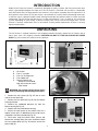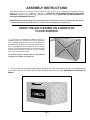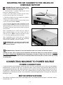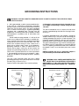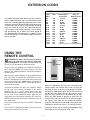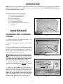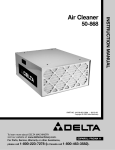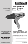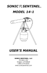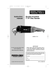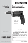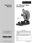
1
50-870
PART NO. 410-10-651-0001 - 03-31-02
Copyright © 2002 Delta Machinery
To learn more about DELTA MACHINERY
visit our website at: www.deltamachinery.com.
For Parts, Service, Warranty or other Assistance,
please call
ESPAÑOL: PÁGINA 11
1-800-223-7278 (In Canada call 1-800-463-3582).
INSTRUCTION MANUAL
Air Cleaner
GENERAL SAFETY RULES
Woodworking can be dangerous if safe and proper operating procedures are not followed. As with all machinery,
there are certain hazards involved with the operation of the product. Using the machine with respect and caution
will considerably lessen the possibility of personal injury. However, if normal safety precautions are overlooked or
ignored, personal injury to the operator may result. Safety equipment such as guards, push sticks, hold-downs,
featherboards, goggles, dust masks and hearing protection can reduce your potential for injury. But even the best
guard won’t make up for poor judgment, carelessness or inattention. Always use common sense and exercise
caution in the workshop. If a procedure feels dangerous, don’t try it. Figure out an alternative procedure that feels
safer. REMEMBER: Your personal safety is your responsibility.
This machine was designed for certain applications only. Delta Machinery strongly recommends that this machine
not be modified and/or used for any application other than that for which it was designed. If you have any questions relative to a particular application, DO NOT use the machine until you have first contacted Delta to determine if it can or should be performed on the product.
Technical Service Manager
Delta Machinery
4825 Highway 45 North
Jackson, TN 38305
(IN CANADA: 505 SOUTHGATE DRIVE, GUELPH, ONTARIO N1H 6M7)
WARNING: FAILURE TO FOLLOW THESE RULES MAY RESULT IN SERIOUS PERSONAL INJURY.
1. FOR YOUR OWN SAFETY, READ AND UNDERSTAND THE INSTRUCTION MANUAL BEFORE OPERATING THE UNIT. Learn the unit’s application and limitations as well as the specific hazards peculiar to it.
2. KEEP WORK AREA CLEAN. Cluttered areas and benches invite accidents.
3. DON’T USE IN DANGEROUS ENVIRONMENT. Don’t use this unit in damp or wet locations, or expose it to
rain. Keep work area well-lighted.
4. KEEP CHILDREN AND VISITORS AWAY. All children and visitors should be kept a safe distance from work
area.
5. DISCONNECT UNIT before servicing.
6. CHECK DAMAGED PARTS. Before further use of the unit, properly repair or replace any part that is
damaged.
2
SAFETY RULES FOR
AIR CLEANERS
1.
DANGER: DO NOT USE THIS UNIT TO FILTER METAL DUST. Combining wood and metal dust can create
an explosion or fire hazard. This unit is intended to filter non-explosive atmospheres only.
2.
WARNING: DUST GENERATED BY CERTAIN WOODS AND WOOD PRODUCTS CAN BE HAZARDOUS
TO YOUR HEALTH.
3.
WARNING: DO NOT USE THIS UNIT TO DISSIPATE FUMES OR SMOKE. This air cleaner is intended for use
where only dry airborne dust is present. Its use should be limited to non-explosive, non-metallic atmospheres.
4. DO NOT OPERATE THIS UNIT UNTIL IT IS COMPLETELY ASSEMBLED AND INSTALLED ACCORDING TO
THE INSTRUCTIONS.
5. OBTAIN ADVICE FROM YOUR SUPERVISOR, INSTRUCTOR, OR ANOTHER QUALIFIED PERSON if you are
not thoroughly familiar with the operation of this unit.
6. FOLLOW ALL WIRING CODES and recommended electrical connections.
7. DO NOT LIFT THIS UNIT BY THE POWER CORD. Do not use the power cord as a hanging device.
8. SECURELY ANCHOR THIS UNIT INTO A SUPPORTING STRUCTURE when suspending it from the ceiling.
Always keep a minimum of 7 feet between the bottom of the unit and the floor surface to allow for sufficient head
clearance. Use only chain rated for a minimum of 150 lb. working load to adequately hold the unit. Use steel SHooks that are at least 1/4" in diameter to suspend the unit from the ceiling. Lag-type bolts used to suspend the
unit from the ceiling must be threaded at least 1-1/2" into supporting structural members.
9. SUPPORT THIS UNIT OR SECURELY CLAMP IT TO THE WORK SURFACE WHEN IT IS USED IN A PORTABLE
APPLICATION to eliminate potential movement and/or damage from falling.
10. INSURE THAT THE INTAKE AND EXHAUST AREAS ARE CLEAR PRIOR TO STARTING THE UNIT.
11. KEEP ARMS, HANDS, AND FINGERS AWAY FROM THE FAN. Avoid all exposure to rotating parts.
12. DO NOT OPERATE THIS UNIT WITHOUT THE FILTERS IN PLACE.
13. DO NOT ATTEMPT TO REMOVE OR REPLACE THE FILTER(S) WHILE THE UNIT IS RUNNING. Make certain
that the unit is disconnected from the power source.
14. MAINTAIN THE UNIT IN TOP CONDITION. Keep filters clean for optimum performance. Follow all instructions for
changing and cleaning filters.
15. STORE THIS UNIT IN A LOCATION that eliminates the potential of damage to the power cord. Safely store power
cord on the unit to eliminate tripping hazards.
16. TURN THE UNIT “OFF” AND DISCONNECT IT FROM THE POWER SOURCE before installing or removing
accessories, or when making repairs.
READ AND SAVE THESE INSTRUCTIONS.
Refer to them often
and use them to instruct others.
3
INTRODUCTION
Model 50-870 Delta Air Cleaner is specifically designed to quietly circulate and filter non-metallic dust
which is generated throughout the work area. The Air Cleaner is furnished with two filters: a disposable
outer filter which filters out larger particles five microns in size; and the secondary filter will capture 91% of
dust particles of one micron in size (one micron = one millionth of a meter). Because breathing microscopic particles can be a potential health hazard, filtering microscopic dust particles offers a cleaner and safer
environment. This Air Cleaner will filter the air in a room measuring 20’ x 20’ x 8’ either 26, 30, or 35 times
an hour, depending on your setting. If desired, multiple units can be used to filter larger areas. The Air
Cleaner is relatively maintenance free. An occasional cleaning and/or replacement of filters is the only
required maintenance.
UNPACKING
The Air Cleaner is shipped complete in one shipping container. Carefully unpack the Air Cleaner and all
loose items from the shipping container. WARNING: DO NOT LIFT THE AIR CLEANER BY POWER
CORD. Fig. 2A illustrates the contents of the container.
A
C
D
B
E
B
A
A
D
C
A
A
Fig. 2A
A
B
C
D
E
-
Fig. 2B
Air cleaner
Four 1” eye-bolts
Four 1/4-20 flange nuts
Four rubber feet
Remote Control Unit
Batteries not included)
Bag with twelve #8 screws
(Not shown)
A
B
WARNING: Do not plug unit into power source
prior to performing the following instructions:
Fig. 2C
1. Remove the four screws (A) Fig. 2B, one on each
side of the rear panel (B).
2. Remove the rear panel (B) Fig. 2B with the blower
housing attached.
3. Remove the cardboard protector (A) from the
blower housing (B) Fig. 2C.
4. Replace the rear panel/blower housing.
5. Secure the back panel to the cabinet with the 4
original screws plus 12 additional #8 pan head screws
(supplied) in the holes provided (A) Fig. 2D.
6. Once these steps have been taken, remove and
discard the warning labels that were attached to both
the rear panel/cabinet (C) Fig. 2B and the end of the
power cord (D).
A
A
A
A
Fig. 2D
4
A
A
A
A
A
A
A
A
ASSEMBLY INSTRUCTIONS
Determine whether the Air Cleaner will be used on the floor, on a bench, or hanging from overhead. If the Air
Cleaner will be used as a mobile unit, proceed to “USING THE AIR CLEANER ON A BENCH OR FLOOR
SURFACE” section. If ceiling mounting is desired, proceed to section “MOUNTING THE AIR CLEANER TO A
CEILING OR OVERHEAD SUPPORT.”
IMPORTANT: When determining where to mount the air cleaner, always select a location where the air flow
is unrestricted. Do not locate the unit in a corner or near any heating or cooling vents.
USING THE AIR CLEANER ON A BENCH OR
FLOOR SURFACE
1. Locate four (4) self-adhesive rubber feet (A) Fig. 3
supplied with the unit. Carefully place the air cleaner on
a firm supporting surface with access to the bottom of
the cabinet (Fig. 3). Apply a self-adhesive rubber foot (A)
Fig. 3 to the bottom at each corner of the air cleaner
cabinet. The rubber feet will help eliminate vibration and
will prevent the possibility of the air cleaner “walking”
across the work or floor surface.
A
For operator safety, clamp the unit to a work bench
or position it securely on sawhorses.
Fig. 3
2. The air cleaner has convenient lifting handles located on both sides of the cabinet (A) Fig. 4. To avoid damage to
the air filters, carry the air cleaner with the filters positioned away from your body. CAUTION: This unit weighs 85
pounds.
A
Fig.4
5
MOUNTING THE AIR CLEANER TO THE CEILING OR
OVERHEAD SUPPORT
WARNING:This unit weighs 85 pounds. When
mounting overhead, make certain that the unit
is securely fastened and supported.
D
1. Locate the four 1” eye-bolts, and the four 1/4-20
flange nuts supplied with the unit.
2. Use a 5/32” Allen wrench to remove the four screws
(C) Fig. 5 from the top of the air cleaner (D).
C
3. Thread one flange nut on the eyebolt until approximately 3/4 of the bolt is exposed.
4. Thread an eye-bolt into each of the four holes where
screws (C) were removed in STEP 2.
D
5. Fig. 6 illustrates the four eye bolts attached to the top
of the air cleaner. NOTE: Be certain the flange nuts are
tightened against the surface of the air cleaner, and that
the eyebolts extend an equal distance above the top of
the air cleaner.
Fig. 5
When suspending the air cleaner from the ceiling or
other overhead support, use steel s-hooks that are a
minimum of 1/4". NOTE: Thread all lag hooks at least
1-1/2" into the supporting structural members.
When suspending the air cleaner from the ceiling or
other overhead support, be certain the supporting
hardware (not supplied) is securely anchored.
WARNING: Never secure the air cleaner hardware to drywall, drop ceiling tile/frame, or other
non-structural members.
Fig. 6
WARNING: Keep a minimum of seven feet between bottom of air cleaner and the floor surface.
DO NOT use rope, cable, or power cord to suspend the unit from the ceiling. Use a chain rated for a minimum
of a 150 lb. working load. IMPORTANT: When determining a location to mount the unit, the air cleaner will
operate more efficiently when the air flow is unrestricted. Do not locate the unit in a corner or near any heating
or cooling vents.
CONNECTING MACHINE TO POWER SOURCE
POWER CONNECTIONS
A separate electrical circuit should be used for your tools. This circuit should not be less than #12 wire and should be
protected with a 20 Amp time lag fuse. If an extension cord is used, use only 3-wire extension cords which have
3-prong grounding type plugs and 3-hole receptacles which accept the tool’s plug. Before connecting the motor to
the power line, make sure the switch is in the “OFF” position and be sure that the electric current is of the same
characteristics as indicated on the tool. All line connections should make good contact. Running on low voltage will
damage the motor.
MOTOR SPECIFICATIONS
This machine is wired for 120 volt, 60 HZ alternating current. The no-load speed of the motor is 1075 RPM, and the
full-load amp is 7.9.
6
GROUNDING INSTRUCTIONS
WARNING: THIS TOOL MUST BE GROUNDED WHILE IN USE TO PROTECT THE OPERATOR FROM
ELECTRIC SHOCK.
2. Grounded, cord-connected tools intended for use
on a supply circuit having a nominal rating less than
150 volts:
1. All grounded, cord-connected tools:
In the event of a malfunction or breakdown, grounding
provides a path of least resistance for electric current to
reduce the risk of electric shock. This tool is equipped
with an electric cord having an equipment-grounding
conductor and a grounding plug. The plug must be
plugged into a matching outlet that is properly installed
and grounded in accordance with all local codes and
ordinances.
This tool is intended for use on a normal 120-volt circuit
and has a grounded plug that looks like the plug illustrated in Fig. 7.
If a properly grounded outlet is not available, a temporary
adapter, shown in Fig. 8, may be used for connecting the
3-prong grounding type plug to a 2-hole receptacle. The
temporary adapter should be used only until a properly
grounded outlet can be installed by a qualified electrician.
The green colored rigid ear, lug, or the like extending from
the adapter must be connected to a permanent ground
such as a properly grounded outlet box cover. Whenever
the adapter is used, it must be held in place with a metal
screw.
Do not modify the plug provided - if it will not fit the
outlet, have a proper outlet installed by a qualified electrician. Improper connection of the equipment-grounding
conductor can result in risk of electric shock. The conductor with insulation having an outer surface that is
green with or without yellow stripes is the equipmentgrounding conductor. If repair or replacement of the
electric cord or plug is necessary, do not connect the
equipment-grounding conductor to a live terminal.
NOTE: In Canada, the use of a temporary adapter is
not permitted by the Canadian Electric Code.
Check with a qualified electrician or service personnel
if the grounding instructions are not completely understood, or if in doubt as to whether the tool is properly
grounded.
Use only 3-wire extension cords that have 3-prong
grounding type plugs and 3-hole receptacles that accept
the tool’s plug, as shown in Fig. 7.
WARNING: IN ALL CASES, MAKE CERTAIN THE
RECEPTACLE IN QUESTION IS PROPERLY
G R O U N D E D . I F Y O U A R E N O T S U R E H AV E A
QUALIFIED ELECTRICIAN CHECK THE RECEPTACLE.
Repair or replace damaged or worn cord immediately.
HOLES
GROUNDED OUTLET BOX
GROUNDED OUTLET BOX
CURRENT
CARRYING
PRONGS
GROUNDING
MEANS
ADAPTER
GROUNDING BLADE
IS LONGEST OF THE 3 BLADES
HOLES
Fig. 7
Fig. 8
7
EXTENSION CORDS
MINIMUM GAUGE EXTENSION CORD
RECOMMENDED SIZES FOR USE WITH STATIONARY ELECTRIC TOOLS
Ampere
Rating
0-6
0-6
0-6
0-6
6-10
6-10
6-10
6-10
10-12
10-12
10-12
10-12
12-16
12-16
12-16
Use proper extension cords. Make sure your extension
cord is in good condition and is a 3-wire extension cord
which has a 3-prong grounding type plug and a 3-hole
receptacle which will accept the tool’s plug. When using
an extension cord, be sure to use one heavy enough to
carry the current of the saw. An undersized cord will
cause a drop in line voltage, resulting in loss of power
and overheating. Fig. 9 shows the correct gauge to
use depending on the cord length. If in doubt, use the
next heavier gauge. The smaller the gauge number, the
heavier the cord.
Volts
120
120
120
120
120
120
120
120
120
120
120
120
120
120
120
Total Length of
Cord in Feet
up to 25
25-50
50-100
100-150
up to 25
25-50
50-100
100-150
up to 25
25-50
50-100
100-150
up to 25
25-50
Gauge of
Extension Cord
18 AWG
16 AWG
16 AWG
14 AWG
18 AWG
16 AWG
14 AWG
12 AWG
16 AWG
16 AWG
14 AWG
12 AWG
14 AWG
12 AWG
GREATER THAN 50 FEET NOT RECOMMENDED
Fig. 9
USING THE
REMOTE CONTROL
WARNING: To reduce the risk of fire or electric
shock, do not use this unit with any solid-state
speed control device. The remote control provided with
this unit is not considered a solid-state device.
A
G
B
H
F
C
The Air Cleaner is equipped with a REMOTE CONTROL
UNIT (Fig.10.A) NOTE: The remote requires two AAA
batteries (not supplied). Batteries should be installed in
the back cover.
Notice that the remote control has three control buttons
(Fig. 10A): TIME (A), ON/OFF (B), and SPEED (C). These
buttons correspond to the LED sensor panel on the rear
of the machine (Fig. 10B). NOTE: When the machine is
connected to the power source, a green light (E) will be
activated on the panel.
E
I
Fig. 10A
Fig. 10B
To turn the machine off, press the “ON/OFF” button (B)
Fig. 10A.
When the TIME button (A) Fig. 10A is pressed on the
remote control, the machine will run for 1/2 hour. (An
LED light will show up on the sensor panel (F) Fig. 10B).
Pressing the TIME button again will set the machine to
run for one hour. Notice that the light on the sensor
panel has now moved to the 1H location (G) Fig. 10B.
When the TIME button is pressed a third time, the
machine will run for 90 minutes. At this point, two lights
will appear - one under the 1H location (G) and one
under the 1/2H location (F) indicating an hour and a half.
Continue this process for up to 7 1/2 hours of run time.
The 50-870 Dust Collector provides a timer that can be
set by remote control. (A) Fig. 10A.
All of these actions can be manually controlled by using
the buttons on the sensor panel (I) Fig. 10B.
To activate the blower unit, press the “ON/OFF” button
(B) Fig. 10A. The machine will begin in the default
speed of low or “L” on the sensor panel. Press the
SPEED button once, and the machine will run at the high
(or “H”) level. Press the SPEED button again and the
machine will run at the medium speed (or “M”). Press the
SPEED button a third time and the machine will return to
low speed mode.
8
OPERATIONS
NOTE: The air cleaner may produce a slight odor for the first few hours of operation due to the protective coating that is
applied to internal components. This odor will dissipate and should be disregarded. IMPORTANT: Never operate the
air cleaner without air filters in place.
The Delta 50-870 air cleaner can be used in
•
•
•
•
•
•
bench-top sanding applications.
circular sawing applications.
dry wall applications.
shop cleaning applications.
floor sanding applications.
any application where non-metallic dust
is a factor.
MAINTENANCE
A
CHANGING AND CLEANING
FILTERS
Fig. 11
1. To remove the outer first stage filter (A) Fig. 11, lift
and pull out the bottom of the filter.
2. Remove inner bag filter (B) Fig. 12 in the same
manner.
3. The first stage filter can be replaced (Delta Catalog.
#50-822) or cleaned depending on its condition. Clean
this filter in one of two methods: use a shop-vac to
remove the dust, or use compressed air (30 psi - maximum) to blow the dust out of the filter.
B
WARNING: Compressed air can be dangerous.
For operator safety, do not exceed an air pressure of 30 psi. Do not point the air nozzle toward
yourself or anyone else. Always wear safety glasses
and a dust mask when using compressed air.
Fig. 12
4. The inner bag filter is disposable and must be
replaced (Delta catalog #50-823). DO NOT try to clean
it.
5. Reinstall the filters. NOTE: To make installation of
the filter easier, place the top of the filter inside the
cabinet first. Push backward until the bottom of the
filter is in place. Then pull the top of the filter into place.
NOTE: The air flow arrow on the outer filter must
point inward toward the rear of the air cleaner.
Location of the air flow arrow is shown at fig. 13.
Fig. 13
9
ACCESSORIES
A complete line of accessories is available from your Delta Supplier, Porter-Cable • Delta Factory Service Centers,
and Delta Authorized Service Stations. Please visit our Web Site www.deltamachinery.com for a catalog or
for the name of your nearest supplier.
WARNING: Since accessories, other than those offered by Delta, have not been tested
with this product, use of such accessories could be hazardous. For safest operation, only
Delta recommended accessories should be used with this product.
PARTS, SERVICE OR WARRANTY ASSISTANCE
All Delta Machines and accessories are manufactured to high quality standards and are serviced by a network of
Porter-Cable • Delta Factory Service Centers and Delta Authorized Service Stations. To obtain additional information
regarding your Delta quality product or to obtain parts, service, warranty assistance, or the location of the nearest
service outlet, please call 1-800-223-7278 (In Canada call 1-800-463-3582).
Delta Building Trades and Home Shop Machinery
Two Year Limited Warranty
Delta will repair or replace, at its expense and at its option, any Delta machine, machine part, or machine accessory which
in normal use has proven to be defective in workmanship or material, provided that the customer returns the product prepaid to a Delta factory service center or authorized service station with proof of purchase of the product within two years
and provides Delta with reasonable opportunity to verify the alleged defect by inspection. Delta may require that electric
motors be returned prepaid to a motor manufacturer’s authorized station for inspection and repair or replacement. Delta
will not be responsible for any asserted defect which has resulted from normal wear, misuse, abuse or repair or alteration
made or specifically authorized by anyone other than an authorized Delta Service facility or representative. Under no circumstances will Delta be liable for incidental or consequential damages resulting from defective products. This warranty is
Delta’s sole warranty and sets forth the customer’s exclusive remedy, with respect to defective products; all other warranties, express or implied, whether of merchantability, fitness for purpose, or otherwise, are expressly disclaimed by Delta.
Printed in U.S.A.
10
PORTER-CABLE • DELTA SERVICE CENTERS
(CENTROS DE SERVICIO DE PORTER-CABLE • DELTA)
Parts and Repair Service for Porter-Cable/Delta Power Tools are Available at These Locations
(Obtenga Refaccion de Partes o Servicio para su Herramienta en los Siguientes Centros de Porter-Cable•Delta)
ARIZONA
Tempe 85282 (Phoenix)
2400 West Southern Avenue
Suite 105
Phone: (602) 437-1200
Fax: (602) 437-2200
CALIFORNIA
Ontario 91761 (Los Angeles)
3949A East Guasti Road
Phone: (909) 390-5555
Fax: (909) 390-5554
San Leandro 94577 (Oakland)
3039 Teagarden Street
Phone: (510) 357-9762
Fax: (510) 357-7939
FLORIDA
Davie 33314 (Miami)
4343 South State Rd. 7 (441)
Unit #107
Phone: (954) 321-6635
Fax: (954) 321-6638
Tampa 33609
4538 W. Kennedy Boulevard
Phone: (813) 877-9585
Fax: (813) 289-7948
GEORGIA
Forest Park 30297 (Atlanta)
5442 Frontage Road,
Suite 112
Phone: (404) 608-0006
Fax: (404) 608-1123
ILLINOIS
Addison 60101 (Chicago)
311 Laura Drive
Phone: (630) 628-6100
Fax: (630) 628-0023
Woodridge 60517 (Chicago)
2033 West 75th Street
Phone: (630) 910-9200
Fax: (630) 910-0360
MARYLAND
Elkridge 21075 (Baltimore)
7397-102 Washington Blvd.
Phone: (410) 799-9394
Fax: (410) 799-9398
MISSOURI
North Kansas City 64116
1141 Swift Avenue
P.O. Box 12393
Phone: (816) 221-2070
Fax: (816) 221-2897
OREGON
Portland 97230
4916 NE 122 nd Ave.
Phone: (503) 252-0107
Fax: (503) 252-2123
St. Louis 63119
7574 Watson Road
Phone: (314) 968-8950
Fax: (314) 968-2790
PENNSYLVANIA
Willow Grove 19090
520 North York Road
Phone: (215) 658-1430
Fax: (215) 658-1433
NEW YORK
Flushing 11365-1595 (N.Y.C.)
175-25 Horace Harding Expwy.
Phone: (718) 225-2040
Fax: (718) 423-9619
MASSACHUSETTS
Braintree 02185 (Boston)
719 Granite Street
Phone: (781) 848-9810
Fax: (781) 848-6759
Franklin 02038 (Boston)
Franklin Industrial Park
101E Constitution Blvd.
Phone: (508) 520-8802
Fax: (508) 528-8089
MICHIGAN
Madison Heights 48071 (Detroit)
30475 Stephenson Highway
Phone: (248) 597-5000
Fax: (248) 597-5004
MINNESOTA
Minneapolis 55429
4315 68th Avenue North
Phone: (763) 561-9080
Fax: (763) 561-0653
TEXAS
Carrollton 75006 (Dallas)
1300 Interstate 35 N, Suite 112
Phone: (972) 446-2996
Fax: (972) 446-8157
NORTH CAROLINA
Charlotte 28270
9129 Monroe Road, Suite 115
Phone: (704) 841-1176
Fax: (704) 708-4625
Houston 77055
West 10 Business Center
1008 Wirt Road, Suite 120
Phone: (713) 682-0334
Fax: (713) 682-4867
OHIO
Columbus 43214
4560 Indianola Avenue
Phone: (614) 263-0929
Fax: (614) 263-1238
WASHINGTON
Renton 98055 (Seattle)
268 Southwest 43rd Street
Phone: (425) 251-6680
Fax: (425) 251-9337
Cleveland 44125
8001 Sweet Valley Drive
Unit #19
Phone: (216) 447-9030
Fax: (216) 447-3097
Authorized Service Stations are located in many large cities. Telephone 800-487-8665 or 731-541-6042 for assistance locating one.
Parts and accessories for Porter-Cable •Delta products should be obtained by contacting any Porter-Cable•Delta Distributor,
Authorized Service Center, or Porter-Cable•Delta Factory Service Center. If you do not have access to any of these, call 888-8485175 and you will be directed to the nearest Porter-Cable•Delta Factory Service Center. Las Estaciones de Servicio Autorizadas están
ubicadas en muchas grandes ciudades. Llame al 800-487-8665 ó al 731-541-6042 para obtener asistencia a fin de localizar una. Las
piezas y los accesorios para los productos Porter-Cable•Delta deben obtenerse poniéndose en contacto con cualquier distribuidor
Porter-Cable•Delta, Centro de Servicio Autorizado o Centro de Servicio de Fábrica Porter-Cable•Delta. Si no tiene acceso a ninguna
de estas opciones, llame al 888-848-5175 y le dirigirán al Centro de Servicio de Fábrica Porter-Cable•Delta más cercano.
CANADIAN PORTER-CABLE • DELTA SERVICE CENTERS
ALBERTA
Bay 6, 2520-23rd St. N.E.
Calgary, Alberta
T2E 8L2
Phone: (403) 735-6166
Fax: (403) 735-6144
BRITISH COLUMBIA
8520 Baxter Place
Burnaby, B.C.
V5A 4T8
Phone: (604) 420-0102
Fax: (604) 420-3522
MANITOBA
1699 Dublin Avenue
Winnipeg, Manitoba
R3H 0H2
Phone: (204) 633-9259
Fax: (204) 632-1976
ONTARIO
505 Southgate Drive
Guelph, Ontario
N1H 6M7
Phone: (519) 836-2840
Fax: (519) 767-4131
QUÉBEC
1515 ave.
St-Jean Baptiste,
Québec, Québec
G2E 5E2
Phone: (418) 877-7112
Fax: (418) 877-7123
1447, Begin
St-Laurent, (Montréal),
Québec
H4R 1V8
Phone: (514) 336-8772
Fax: (514) 336-3505
The following are trademarks of PORTER-CABLE•DELTA (Las siguientes son marcas registradas de PORTER-CABLE S.A.): BAMMER®,
INNOVATION THAT WORKS®, JETSTREAM®, LASERLOC®, OMNIJIG®, POCKET CUTTER®, PORTA-BAND®, PORTA-PLANE®, PORTERCABLE®, QUICKSAND®, SANDTRAP®, SAW BOSS®, SPEED-BLOC®, SPEEDMATIC®, SPEEDTRONIC®, STAIR-EASE®, THE PROFESSIONAL EDGE®, THE PROFESSIONAL SELECT®, TIGER CUB®, TIGER SAW®, TORQBUSTER®, WHISPER SERIES®, DURATRONIC™, FLEX™,
FRAME SAW™, MICRO-SET™, MORTEN™, NETWORK™, RIPTIDE™, TRU-MATCH™, WOODWORKER’S CHOICE™.
Trademarks noted with ® are registered in the United States Patent and Trademark Office and may also be registered in other countries.
Las Marcas Registradas con el signo de ® son registradas por la Oficina de Registros y Patentes de los Estados Unidos y también
pueden estar registradas en otros países.
Printed in U.S.A.
20