1
EMC Host Connectivity with QLogic
Fibre Channel and iSCSI Host Bus Adapters (HBAs)
and Converged Network Adapters (CNAs) in the
Windows Environment
P/N 300-001-164
REV 29
EMC Corporation
Corporate Headquarters:
Hopkinton, MA 01748-9103
1-508-435-1000
www.EMC.com
Copyright © 2001–2013 EMC Corporation. All rights reserved.
Published May 2013
EMC believes the information in this publication is accurate as of its publication date. The information is
subject to change without notice.
THE INFORMATION IN THIS PUBLICATION IS PROVIDED "AS IS." EMC CORPORATION MAKES NO
REPRESENTATIONS OR WARRANTIES OF ANY KIND WITH RESPECT TO THE INFORMATION IN THIS
PUBLICATION, AND SPECIFICALLY DISCLAIMS IMPLIED WARRANTIES OF MERCHANTABILITY OR
FITNESS FOR A PARTICULAR PURPOSE.
Use, copying, and distribution of any EMC software described in this publication requires an applicable
software license.
EMC2, EMC, and the EMC logo are registered trademarks or trademarks of EMC Corporation in the United
State and other countries. All other trademarks used herein are the property of their respective owners.
For the most up-to-date regulator document for your product line, go to EMC Online Support
(https://support.emc.com).
2
EMC Host Connectivity with QLogic Fibre Channel HBAs and CNAs in the Windows Environment
Contents
Preface............................................................................................................................ 11
Chapter 1
Installation and Configuration
How this guide works......................................................................
Downloading latest QLogic drivers/firmware/BIOS
files ...............................................................................................
Installing the adapter .......................................................................
Special installation sequence for Stratus ftServers and
EMC VNX series or CLARiiON systems................................
Matching the adapter with the correct PCI slot ....................
Fibre Channel over Ethernet (FCoE) ..............................................
Booting from the external storage array........................................
Create a floppy disk with the EMC-approved driver and
BIOS .............................................................................................
Install/upgrade firmware and boot BIOS from DOS...........
QLogic Fibre Channel adapter BIOS/boot LUN settings....
Verifying array/LUN visibility for boot ................................
Installing a RAMDISK under the EFI shell ............................
Installing the Windows operating system.....................................
Windows 2000/2003 internal or external boot disk
installation ..................................................................................
Windows 2008 internal or external boot disk installation ...
Windows 2008 Server Core operating system option..................
Limitations..................................................................................
EMC support ..............................................................................
Installing adapter driver and software utilities............................
Pre-installation guidelines........................................................
Driver installation/upgrade ....................................................
Post-installation procedures.....................................................
EMC Host Connectivity with QLogic Fibre Channel HBAs and CNAs in the Windows Environment
16
16
18
19
20
25
26
26
27
28
53
53
55
55
63
73
74
74
76
76
77
86
3
Contents
Show SAN .................................................................................. 90
FCoE converged network adapter (CNA) procedures................ 91
Overview .................................................................................... 91
Installing Fibre Channel BIOS and firmware on a QLogic
CNA............................................................................................. 93
Installing Menlo firmware on a QLogic CNA....................... 97
Installing or upgrading the driver and utilities on a
QLogic QLE8242 CNA............................................................ 101
Updating adapter firmware on a QLogic QLE8242
CNA........................................................................................... 105
Configuring QLogic FAST!UTIL 10 GbE iSCSI BIOS/
boot LUN settings for QLE8242 iSCSI adapters.................. 117
Establishing connectivity to the storage array ........................... 127
Verifying connectivity to the storage array................................. 128
Verifying connectivity through QLogic SANSurfer........... 128
Verifying connectivity using the Server Manager.............. 130
Installing additional Unisphere/Navisphere Host Agent
software............................................................................................ 133
Chapter 2
Miscellaneous Planning and Procedures
Zoning and connection planning in a fabric environment .......
Installing and configuring the QLogic QLA40xx and
QLe40xx iSCSI adapter (TOE).......................................................
Using the QLogic iSCSI SANsurfer application to
configure iSCSI devices ..........................................................
Configuring iSNS settings for QLA4010 ..............................
Booting from SAN with QLogic QLA40xx and Microsoft
Initiator.............................................................................................
Boot-from-SAN configuration restrictions..................................
Benefits of booting from the storage array ..........................
Setting up external boot for IBM BladeCenter server HS40
(8839) ................................................................................................
Configuring an HS40 BladeCenter server to boot from
an external array ......................................................................
Blade server restrictions .........................................................
Manually installing the adapter driver – Advanced users.......
Where to find the driver .........................................................
Required Windows STORPort updates ...............................
Migrating Windows 2003 drivers from SCSI to STOR.......
Manual driver installation procedure for Windows
2000, 2003, or Windows 2008 hosts.......................................
4
136
137
137
140
146
156
156
157
157
158
159
159
159
160
160
EMC Host Connectivity with QLogic Fibre Channel HBAs and CNAs in the Windows Environment
Contents
Updating the adapter driver in a Windows 2000, 2003,
or Windows 2008 hosts ........................................................... 162
Upgrading to Windows 2003 from Windows 2000............. 165
Editing the Windows time-out value.................................... 166
QLogic advanced utilities .............................................................. 167
Updating QLogic firmware/BIOS and applying
NVRAM settings ...................................................................... 167
Updating the flash BIOS using SANsurfer FC HBA
Manager..................................................................................... 168
Procedure for replacing a QLogic adapter in Stratus
ftServers without rebooting ........................................................... 171
EMC VNX series or CLARiiON storage systems ................ 171
EMC Symmetrix arrays with device masking enabled ...... 172
Special instructions for the EMC CLARiiON CX200 series ...... 174
Set the adapter FC-AL loop ID............................................... 174
Direct-connect dual-host clustering configurations............ 176
QLogic NPIV solution .................................................................... 178
QLogic FC adapter NPIV solution ........................................ 178
Chapter 3
Troubleshooting
Operating system/driver capabilities and limitations .............. 182
LUNs.......................................................................................... 182
Volume sizes ............................................................................. 182
Extended error logging by QLogic drivers.................................. 184
Understanding persistent binding................................................ 185
Understanding queue depth ......................................................... 188
Known issues ................................................................................... 190
Problems and solutions .................................................................. 191
Problem 1................................................................................... 191
Problem 2................................................................................... 191
Problem 3................................................................................... 191
Problem 4................................................................................... 192
Problem 5................................................................................... 192
Problem 6................................................................................... 192
Problem 7................................................................................... 193
Problem 8................................................................................... 193
Problem 9 .................................................................................. 193
Event codes from the QLogic STORPort driver.......................... 194
Appendix A
Third-Party Software
QLogic SANsurfer SANblade Manager ...................................... 196
EMC Host Connectivity with QLogic Fibre Channel HBAs and CNAs in the Windows Environment
5
Contents
6
EMC Host Connectivity with QLogic Fibre Channel HBAs and CNAs in the Windows Environment
Figures
Title
1
2
3
4
5
6
7
8
9
10
11
12
13
14
15
16
17
18
19
20
21
22
23
24
25
26
27
28
29
30
Page
Installation and configuration overview ....................................................
PCI slot types and voltage key locations ....................................................
Adapter edge connectors ..............................................................................
PCI Express slots ............................................................................................
PCI Express slots aligned ..............................................................................
QLogic banner ................................................................................................
Main Fast!UTIL options window .................................................................
Configuration Settings window ...................................................................
Adapter Settings window .............................................................................
Configuration Settings window ...................................................................
Selectable Boot Settings window .................................................................
Select Fibre Channel Device window ..........................................................
Example of LUN 17 allocated to adapter ....................................................
Selectable Boot Settings window .................................................................
Warning dialog ...............................................................................................
Fast!UTIL Options window ..........................................................................
Typical QLogic BIOS banner screen ............................................................
Firmware boot manager menu .....................................................................
Device mapping table ....................................................................................
Reference to QLogic Fibre Channel driver .................................................
QLogic directory .............................................................................................
Fibre Channel Card Efi utility ......................................................................
QLogic efiutil all upgrade .............................................................................
Data loaded onto adapter(s) installed in server .........................................
QLogic adapter instances with specific firmware version .......................
QLogic Fibre Channel drivers ......................................................................
Driver handle numbers .................................................................................
Fibre Channel driver configuration utility .................................................
Edit adapter settings ......................................................................................
Connection option ..........................................................................................
EMC Host Connectivity with QLogic Fibre Channel HBAs and CNAs in the Windows Environment
17
21
21
22
23
29
30
30
31
31
32
33
34
35
35
36
36
40
41
42
43
44
45
46
47
47
48
49
49
50
7
Figures
31
32
33
34
35
36
37
38
39
40
41
42
43
44
45
46
47
48
49
50
51
52
53
54
55
56
57
58
59
60
61
62
63
64
65
66
67
68
69
70
71
72
73
8
Example array port WWN and LUN values ..............................................
Options set ......................................................................................................
Example blkD as array port ..........................................................................
Windows Setup screen with F6 prompt .....................................................
Specifying a driver for your adapter ...........................................................
Adapter selection screen ...............................................................................
Windows setup screen ..................................................................................
Existing partitions ..........................................................................................
Windows Boot Manager ...............................................................................
Windows Setup screen ..................................................................................
Windows Install screen .................................................................................
Windows operating system selection screen .............................................
Microsoft Software License Terms screen ..................................................
Windows setup screen ..................................................................................
Load driver screen .........................................................................................
Loading driver screen ....................................................................................
Browse for Folder screen ...............................................................................
Specifying a driver for your adapter ...........................................................
Windows installation prompt screen ..........................................................
Install Windows screen .................................................................................
Server Core installation example .................................................................
QLogic SANsurfer driver install wizard ....................................................
QLogic SANsurfer adapter utility installation ..........................................
Starting SANsurfer utility from the command line ..................................
SANsurfer Driver Install Wizard for Windows ........................................
HBA Configuration Update dialog box ......................................................
Select Driver Installation Type dialog box .................................................
SANsurfer driver location dialog box .........................................................
SANsurfer installation with version number ............................................
Updating Driver dialog box .........................................................................
SANsurfer Java agent service message .......................................................
Installing Driver dialog box ..........................................................................
Driver Update Completed dialog box ........................................................
HBA Configuration update dialog box .......................................................
Select HBA dialog box ...................................................................................
Attach Storage dialog box .............................................................................
Diagnostics results dialog box .....................................................................
Show SAN tree ...............................................................................................
Device Manager ..............................................................................................
SANsurfer utility ............................................................................................
Utilities tab ......................................................................................................
Open dialog box .............................................................................................
Security Check dialog box ............................................................................
51
52
52
57
58
59
60
61
64
64
65
65
66
67
67
68
69
70
71
72
73
74
75
75
77
78
79
80
81
82
83
84
85
86
87
88
89
90
92
93
94
95
96
EMC Host Connectivity with QLogic Fibre Channel HBAs and CNAs in the Windows Environment
Figures
74
75
76
77
78
79
80
81
82
83
84
85
86
87
88
89
90
91
92
93
94
95
96
97
98
99
100
101
102
103
104
105
106
107
108
109
110
111
112
113
114
115
116
Flash Update dialog box ................................................................................ 96
SANsurfer utility ............................................................................................ 97
Utilities tab ....................................................................................................... 98
Open dialog box .............................................................................................. 99
Security Check dialog box ........................................................................... 100
Flash update dialog box ............................................................................... 100
QConverged Console Driver Install Wizard ............................................ 101
End User License Agreement ..................................................................... 102
Installation options ....................................................................................... 103
Installation progress ..................................................................................... 104
Installation complete .................................................................................... 105
QConvergeConsole Installer Introduction window ................................ 106
Tomcat Port Number Setup window ........................................................ 107
Pre-Installation Summary window ............................................................ 108
Enable SSL feature dialog box .................................................................... 108
Installation Complete window ................................................................... 109
QConvergeConsole GUI .............................................................................. 110
Port Info tab ................................................................................................... 111
Wizards > Flash Update Wizard (SAN) .................................................... 112
SAN Flash Update Wizard, Add localhost ............................................... 113
File Selection window .................................................................................. 114
Confirm Changes window .......................................................................... 115
Security Check ............................................................................................... 115
Flash Update Status window ...................................................................... 116
Finish .............................................................................................................. 117
QLogic Fast!UTIL 10 GbE iSCSI BIOS banner .......................................... 118
QLogic Fast!UTIL iSCSI Select Utility page .............................................. 118
Individual adapter configuration options ................................................ 119
Configuration setting details ...................................................................... 120
Host Adapter Settings .................................................................................. 121
Initiator IP Settings ....................................................................................... 122
iSCSI Boot Settings ....................................................................................... 123
List of targets connected to the host .......................................................... 124
Primary Boot Device Settings ..................................................................... 125
QLogic Fast!UTIL 10 GbE iSCSI BIOS banner .......................................... 126
SANsurfer icon .............................................................................................. 128
Connect to the host ....................................................................................... 129
SANsurfer, SANsurfer FC HBA manager ................................................ 130
Server Manager window: Storage controllers pane ................................ 131
Server Manager window: Disk drives pane ............................................. 132
SANsurfer iSCSI HBA Manager, connect to host .................................... 138
SANsurfer iSCSI HBA Manager, HBA Options ....................................... 139
SANsurfer iSCSI HBA Manager, HBA Options, Firmware tab ............. 141
EMC Host Connectivity with QLogic Fibre Channel HBAs and CNAs in the Windows Environment
9
Figures
117
118
119
120
121
122
123
124
125
126
127
10
Download Firmware dialog box ................................................................
SANsurfer iSCSI HBA Manager, HBA Options, BIOS tab .....................
SANsurfer iSCSI HBA Manager, Target Settings tab .............................
SANsurfer iSCSI HBA Manager, Target Settings, IP Address dialog ..
Authentication Configuration, CHAP tab ................................................
SANsurfer iSCSI HBA Manager, Information tab ..................................
Utilities tabbed page ....................................................................................
Reconfigure the adapter jumper ................................................................
N_Port ID sharing ........................................................................................
Original configuration before the reboot ..................................................
Host after the rebooted ................................................................................
142
143
143
143
144
145
169
177
178
187
187
EMC Host Connectivity with QLogic Fibre Channel HBAs and CNAs in the Windows Environment
Tables
Title
1
2
3
4
5
Page
EMC-supported QLogic adapters ................................................................23
Pre-configured parameters for 1 and 2 Gb/s ..............................................37
Pre-configured parameters for 4 Gb/s .........................................................38
Pre-configured parameters for 8 Gb/s and 16 Gb/s ..................................39
Blade servers/QLogic software support matrix .......................................158
EMC Host Connectivity with QLogic Fibre Channel HBAs and CNAs in the Windows Environment
11
Tables
12
EMC Host Connectivity with QLogic Fibre Channel HBAs and CNAs in the Windows Environment
Preface
As part of an effort to improve and enhance the performance and capabilities
of its product line, EMC from time to time releases revisions of its hardware
and software. Therefore, some functions described in this document may not
be supported by all revisions of the software or hardware currently in use.
For the most up-to-date information on product features, refer to your
product release notes.
Audience
Related
documentation
This guide is intended for customers who need to install an
EMC-approved QLogic host bus adapter (HBA) or converged
network adapter (CNA) into a Windows host environment or to
configure the Windows host for connection to an EMC storage array.
Related documents, which can be found on https://support.emc.com,
include:
◆
EMC Host Connectivity Guide for Windows
◆
EMC Unisphere documentation
◆
EMC Navisphere documentation
◆
EMC ControlCenter Navisphere Host Agent and CLI for Windows
2000 and NT Version 6.X Installation Guide
◆
Storage-System Host Utilities for Windows 2000 and NT
Administrator's Guide
◆
PowerPath for Windows Installation And Administration Guide
EMC Host Connectivity with QLogic Fibre Channel HBAs and CNAs in the Windows Environment
11
Preface
IMPORTANT
Always consult the EMC Support Matrix, available through E-Lab
Interoperability Navigator at: http://elabnavigator.EMC.com, under
the PDFs and Guides tab, for the most up-to-date information.
Conventions used in
this guide
EMC uses the following conventions for notes, cautions, and
warnings.
Note: A note presents information that is important, but not hazard-related.
IMPORTANT
An important notice contains information essential to operation of
the software.
Typographical conventions
EMC uses the following type style conventions in this document:
Normal
Used in running (nonprocedural) text for:
• Names of interface elements (such as names of windows,
dialog boxes, buttons, fields, and menus)
• Names of resources, attributes, pools, Boolean expressions,
buttons, DQL statements, keywords, clauses, environment
variables, filenames, functions, utilities
• URLs, pathnames, filenames, directory names, computer
names, links, groups, service keys, file systems, notifications
Bold
Used in running (nonprocedural) text for:
• Names of commands, daemons, options, programs,
processes, services, applications, utilities, kernels,
notifications, system call, man pages
Used in procedures for:
• Names of interface elements (such as names of windows,
dialog boxes, buttons, fields, and menus)
• What user specifically selects, clicks, presses, or types
12
Italic
Used in all text (including procedures) for:
• Full titles of publications referenced in text
• Emphasis (for example a new term)
• Variables
Courier
Used for:
• System output, such as an error message or script
• URLs, complete paths, filenames, prompts, and syntax when
shown outside of running text
EMC Host Connectivity with QLogic Fibre Channel HBAs and CNAs in the Windows Environment
Preface
Where to get help
Courier bold
Used for:
• Specific user input (such as commands)
Courier italic
Used in procedures for:
• Variables on command line
• User input variables
<>
Angle brackets enclose parameter or variable values supplied by
the user
[]
Square brackets enclose optional values
|
Vertical bar indicates alternate selections - the bar means “or”
{}
Braces indicate content that you must specify (that is, x or y or z)
...
Ellipses indicate nonessential information omitted from the
example
EMC support, product, and licensing information can be obtained on
the EMC Online Support site as described next.
Note: To open a service request through the EMC Online Support site, you
must have a valid support agreement. Contact your EMC sales representative
for details about obtaining a valid support agreement or to answer any
questions about your account.
Product information
For documentation, release notes, software updates, or for
information about EMC products, licensing, and service, go to the
EMC Online Support site (registration required) at:
https://support.EMC.com
Technical support
EMC offers a variety of support options.
Support by Product — EMC offers consolidated, product-specific
information on the Web at:
https://support.EMC.com/products
The Support by Product web pages offer quick links to
Documentation, White Papers, Advisories (such as frequently used
Knowledgebase articles), and Downloads, as well as more dynamic
content, such as presentations, discussion, relevant Customer
Support Forum entries, and a link to EMC Live Chat.
EMC Host Connectivity with QLogic Fibre Channel HBAs and CNAs in the Windows Environment
13
Preface
EMC Live Chat — Open a Chat or instant message session with an
EMC Support Engineer.
eLicensing support
To activate your entitlements and obtain your Symmetrix license files,
visit the Service Center on https://support.EMC.com, as directed on
your License Authorization Code (LAC) letter e-mailed to you.
For help with missing or incorrect entitlements after activation (that
is, expected functionality remains unavailable because it is not
licensed), contact your EMC Account Representative or Authorized
Reseller.
For help with any errors applying license files through Solutions
Enabler, contact the EMC Customer Support Center.
If you are missing a LAC letter, or require further instructions on
activating your licenses through the Online Support site, contact
EMC's worldwide Licensing team at [email protected] or call:
◆
North America, Latin America, APJK, Australia, New Zealand:
SVC4EMC (800-782-4362) and follow the voice prompts.
◆
EMEA: +353 (0) 21 4879862 and follow the voice prompts.
We'd like to hear from you!
Your suggestions will help us continue to improve the accuracy,
organization, and overall quality of the user publications. Send your
opinions of this document to:
[email protected]
14
EMC Host Connectivity with QLogic Fibre Channel HBAs and CNAs in the Windows Environment
1
Invisible Body Tag
Installation and
Configuration
This chapter describes the procedures for installing an
EMC-approved QLogic adapters into a Microsoft Windows host
environment and configuring the Windows host for connection to an
EMC storage array over Fibre Channel.
Note: Review the EMC Support Matrix for the latest information on approved
adapters and drivers.
◆
◆
◆
◆
◆
◆
◆
◆
◆
◆
◆
How this guide works ....................................................................... 16
Installing the adapter......................................................................... 18
Fibre Channel over Ethernet (FCoE) ............................................... 25
Booting from the external storage array ......................................... 26
Installing the Windows operating system...................................... 55
Windows 2008 Server Core operating system option................... 73
Installing adapter driver and software utilities............................. 76
FCoE converged network adapter (CNA) procedures ................. 91
Establishing connectivity to the storage array............................. 127
Verifying connectivity to the storage array .................................. 128
Installing additional Unisphere/Navisphere Host Agent
software ............................................................................................. 133
Installation and Configuration
15
Installation and Configuration
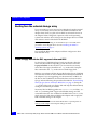
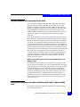
How this guide works
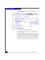
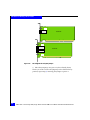
In an effort to simplify the installation and configuration of QLogic
Fibre Channel adapters, this guide follows a simple flow chart, as
shown in Figure 1 on page 17, that guides you through the necessary
procedures to connect your Windows server to EMC storage arrays.
Tips on planning, miscellaneous procedures, and troubleshooting
information are located in Chapter 2, ”Miscellaneous Planning and
Procedures,” and Chapter 3, ”Troubleshooting.”
This document will guide you through the following steps:
1. “Installing the adapter” on page 18
2. “Booting from the external storage array” on page 26:
a. If not installing an IA-64 or EFI-based server:
– “Create a floppy disk with the EMC-approved driver and
BIOS” on page 26.
– “Install/upgrade firmware and boot BIOS from DOS” on
page 27.
– “QLogic Fibre Channel adapter BIOS/boot LUN settings”
on page 28.
– “Verifying array/LUN visibility for boot” on page 53.
b. If installing an IA-64 or EFI-based server:
– “Installing a RAMDISK under the EFI shell” on page 53
3. “Installing the Windows operating system” on page 55.
4. “Installing adapter driver and software utilities” on page 76.
5. “Verifying connectivity to the storage array” on page 128.
Downloading latest QLogic drivers/firmware/BIOS files
Throughout this document, there are references to updated files from
QLogic. All of the versions included on the QLogic CD packaged
with your adapter are current as of this documents release. However,
there may be updates to these files that may be necessary to
download. For these, use the QLogic website,
http://www.qlogic.com. From the main page on the QLogic website,
click Downloads on the top of the page. On the resulting support
page, click the EMC link under the OEM Models section. On the
resulting page, click the EMC Array category for your storage array.
16
EMC Host Connectivity with QLogic Fibre Channel HBAs and CNAs in the Windows Environment
Installation and Configuration
On the resulting EMC Approved Software page, it is possible to
download the most recent EMC-approved drivers and BIOS files as
well as documentation and helpful software tools.
Start
Installing the HBA(s) into the server
Booting
from the external
storage arrays?
Booting from the External
Storage Array
YES
Create a floppy disk
with EMC-approved
driver, firmware, and
boot BIOS
N
Are you
installing an IA-64
or EFI-based
server?
Y
NO
Copy the EMC-approved
driver and firmware, and
the Intel EFI RAMDISK
driver to a USB pen drive
or floppy disk to be used
in a USB floppy drive
Install firmware and
boot BIOS from DOS
Install firmware and
EFIBoot driver from
EFI Shell
Configure the
QLogic Boot BIOS
Configure the
EFIBoot driver
Verify Array/LUN
Visibility for Boot
Install Windows OS
Install HBA Driver and
Software Utilities
Verify Connectivity to the
Storage Array
Figure 1
GEN-000017Q
Installation and configuration overview
How this guide works
17
Installation and Configuration
Installing the adapter
Follow the instructions included with your adapter. The adapter
installs into a single slot.
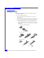
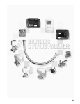
To connect the cable to the adapter:
1. (Optical cable only) Remove the protective covers on each
fiber-optic cable.
2. Plug one end of the cable into the connector on the adapter as
shown in the appropriate figure in this step. (The hardware might
be rotated 90 degrees clockwise from the orientation shown.)
• Fibre Channel adapter connectivity options include copper
cable with DB9 connector, SC optical, and LC optical cable, as
shown next.
– Copper cable with DB9 connector:
– SC optical cable:
1
2
3
– LC optical cable:
1
18
2
3
EMC Host Connectivity with QLogic Fibre Channel HBAs and CNAs in the Windows Environment
Installation and Configuration
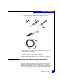
• Fibre Channel over Ethernet CNA connectivity options
include LC optical and SFP+, shown next.
– LC optical cable:
1
2
3
– SFP+ (Twinax cable)
3. Plug the other end of the cable into a connector on the storage
system or a hub/switch port.
4. Label each cable to identify the adapter and the
storage/switch/hub port to which it connects.
5. After connecting all adapters in the server, power up the server.
Special installation sequence for Stratus ftServers and EMC VNX series or
CLARiiON systems
A specific installation sequence is required when installing QLogic
adapters with the Stratus ft Servers and EMC® VNX™ series and
CLARiiON® storage. Failure to follow this sequence may result in a
STOP: 0X0000007B bugcheck error when booting the Stratus server
Installing the adapter
19
Installation and Configuration
for the first time when connected to EMC VNX series or CLARiiON
storage.
With the Stratus ftServer, if the adapter detects EMC VNX series or
CLARiiON targets but no accessible LUNs, it prevents the Stratus
server from booting. In this configuration, the Stratus ftServer
attempts to boot from the array, instead of booting from the internal
boot drive.
To avoid this issue before storage is correctly assigned, either boot the
Stratus ftServer before connecting the fibre cables to the adapters or,
if connected to a fabric, disable the adapter ports on the switch before
booting the ftServer.
After the system boots, connect the cables or re-enable the switch
ports. Verify the adapters are logged in to the EMC VNX series or
CLARiiON system; then stop and restart the
Unisphere™/Navisphere® agent on the ftServer host. This will
register the adapters with the VNX series or CLARiiON system and
allow the adapter to properly detect the available LUNs.
Matching the adapter with the correct PCI slot
When choosing an adapter for your server, it is important to know
which adapter is compatible with your server’s PCI/PCI-X/PCI
Express slots. Certain adapter models have specific voltage
requirements or physical limitations that allow them to only work in
specific slots.
Servers today have several different bus slot types for accepting
adapters. PCI, PCI-X, PCI-X 2.0, and PCI-Express.
PCI slots can be 32-bit and 64-bit (denoted by their 124-pin or 188-pin
connectors). These slots have plastic “keys” that prevent certain
adapters from fitting into them. These keys work with the cutout
notches in the adapter edge connector so that only compatible
adapters will fit into them. This is done because of the voltage
characteristics of the adapter. Inserting a 3.3v adapter into a 5v slot
would cause severe damage to both the adapter and the server.
Therefore, the slot keys denote the type of voltage provided by the
slot and effectively prevent a voltage incompatible adapter from
being inserted.
20
EMC Host Connectivity with QLogic Fibre Channel HBAs and CNAs in the Windows Environment
Installation and Configuration
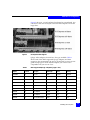
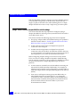
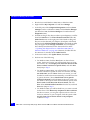
Figure 2 shows how PCI slots will appear with their keys and what
type of voltage is provided for each slot type.
Figure 2
PCI slot types and voltage key locations
Figure 3 on page 21 shows the adapter edge connectors compatible
with the PCI slots shown in Figure 1 on page 17. Note adapter #5
which shows a universal adapter edge connector. Universal adapters
are compatible with both 3.3v and 5v PCI slots.
Figure 3
Adapter edge connectors
Installing the adapter
21
Installation and Configuration
PCI-X (or PCI Extended) slots increase the speed that data travels
over the bus. PCI-X slots appear identical to a 64-Bit PCI slot keyed
for 3.3v. (Refer to number 3 in Figure 2 on page 21 and Figure 3 on
page 21.) PCI-X slots are backwards compatible with 3.3v PCI
adapters and universal adapters. Inserting standard PCI adapters
into PCI-X slots will lower the bus speed, however, as they cannot
take advantage of the improved performance.
PCI-X 2.0 is the next generation of PCI-X buses. PCI-X 2.0 increases
the bus speed providing more performance for adapters. PCI-X 2.0
slots also appear identical to a 64-bit PCI slot keyed for 3.3v. (Refer to
number 3 in Figure 2 and Figure 3.) PCI-X 2.0 is also fully
backward-compatible with 3.3v PCI and PCI-X.
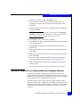
PCI Express (sometimes noted as PCIe) is a new bus type that uses
the existing PCI model, but implements it in a faster, serial protocol.
Because of the serial way it transmits data, the PCI Express bus slot
can be different sizes depending on the throughput it supports. PCI
Express slot speeds are expressed in "lanes" and are normally shown
as x1, x4, x8, and x16. Each type of slot are different lengths (Figure 4)
and adapter edge connectors will also have varying lengths
depending on how many lanes they require for throughput. Because
of how PCI Express slots are keyed, an x1 adapter can be inserted in
all 4 slot types as the adapter will negotiate with the slot to determine
the highest mutually supported number of lanes. However, an
adapter requiring x16 lanes will not fit into a smaller slot.
Figure 4
22
PCI Express slots
EMC Host Connectivity with QLogic Fibre Channel HBAs and CNAs in the Windows Environment
Installation and Configuration
Figure 5 shows x1, x4, and x16 lane slots aligned on a mainboard. You
can see how the slots are keyed so that low-lane adapters can fit into
larger slots.
Figure 5
PCI Express slots aligned
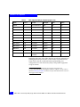
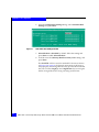
QLogic offers adapters for each bus/slot type available. Table 1
shows each of the EMC-supported QLogic adapters, and their
respective slot requirements. Be sure to consult both your server user
guide and QLogic to insure that the adapter you want to use is
compatible with your server’s bus.
Table 1
EMC-supported QLogic adapters (page 1 of 2)
Adapter
Protocol
PCI spec
BUS length
Power
Slot key
QLA2200F
FC
PCI 2.1
64-bit
3.3V, 5V
Universal
QLA200
FC
PCI-X 1.0a & PCI 2.2
32-bit
3.3V, 5V
3.3V
QLA210
FC
PCI-X 1.0a & PCI 2.2
32-bit
3.3V
3.3V
QLA2310F
FC
PCI-X 1.0a & PCI 2.2
64-bit
3.3V, 5V
Universal
QLA2340LF
FC
PCI-X 1.0a & PCI 2.2
64-bit
3.3V, 5V
Universal
QLA2342LF
FC
PCI-X 1.0a & PCI 2.2
64-bit
3.3V, 5V
Universal
QLE2360
FC
PCI Express
x4 lane
3.3V
n/a
QLE2362
FC
PCI Express
x4 lane
3.3V
n/a
QLA2460
FC
PCI-X 2.0a & PCI 2.3
64-bit
3.3V
3.3V
Installing the adapter
23
Installation and Configuration
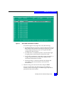
Table 1
EMC-supported QLogic adapters (page 2 of 2)
Adapter
Protocol
PCI spec
BUS length
Power
Slot key
QLA2462
FC
PCI-X 2.0a & PCI 2.3
64-bit
3.3V
3.3V
QLE2460
FC
PCI Express
x4 lane
3.3V
n/a
QLE2462
FC
PCI Express
x4 lane
3.3V
n/a
QLE220
FC
PCI Express
x4 lane
3.3V
n/a
QLE2560
FC
PCI Express
x4 lane
3.3V
n/a
QLE2562
FC
PCI Express
x4 lane
3.3V
n/a
QLE8042
FCoE
PCI Express
x8 lane
3.3V
n/a
QLE8140/8142
FCoE
PCI Express
x4/x8 lane
3.3V
n/a
QLE8150/8152
FCoE
PCI Express
x4/x8 lane
3.3V
n/a
QLE8242-CU
FCoE
PCI Express
x4/x8 lane
3.3V
n/a
QLE8242-SR
FCoE
PCI Express
x4/x8 lane
3.3V
n/a
QLE2670/QLE2672
FC
PCI Express
Gen2/Gen3
x8/x4 lane
n/a
n/a
Remember that some of the older adapters are tall (also referred to as
full-height) and may not fit into a server with a low-profile chassis.
These factors must be considered before implementing your
configuration to avoid unnecessary delays and possible equipment
swaps or returns.
Note: The QLogic QLE8042 FCoE CNA requires servers that can
accommodate full-height, full-length PCI Express adapters. Always refer to
the latest EMC Support Matrix for the most up-to-date information on servers
that support these adapters.
24
EMC Host Connectivity with QLogic Fibre Channel HBAs and CNAs in the Windows Environment
Installation and Configuration
Fibre Channel over Ethernet (FCoE)
EMC supports QLogic Fibre Channel over Ethernet (FCoE)
Converged Network Adapter (CNA). FCoE adapters represent a
method to converge both Fibre Channel and Ethernet traffic over a
single physical link to a switch infrastructure that manages both
storage (SAN) and network (IP) connectivity within a single unit.
The benefits of FCoE technology become apparent in large data
centers:
◆
Where dense, rack-mounted and blade server chassis exist
◆
Where physical cable topology simplification is a priority
◆
In virtualization environments, where several physical storage
and network links are commonly required
The installation of the QLogic FCoE CNA provides the host with an
Intel-based 10 Gb Ethernet interface (using the existing in-box
drivers), and a QLogic Fibre Channel adapter interface
Upon installation of the proper driver for the FCoE CNA, the Fibre
Channel interface will function identically to that of a standard
QLogic Fibre Channel HBA. The FCoE CNA simply encapsulates
Fibre Channel traffic within Ethernet frames. As such, FC-based
content within this guide also applies directly to QLogic FCoE CNAs.
In-depth information about FCoE and its supported features and
topologies can be found in the "Fibre Channel over Ethernet (FCoE)"
chapter of the EMC Networked Storage Topology Guide, available
through E-Lab Interoperability Navigator at:
http://elabnavigator.EMC.com.
For CNA configuration procedures, refer to “FCoE converged
network adapter (CNA) procedures” on page 91.
Fibre Channel over Ethernet (FCoE)
25
Installation and Configuration
Booting from the external storage array
If you are setting up your server to boot Windows from the external
array, it is necessary to have the most recent BIOS installed on the
adapter from which you plan to boot. BIOS is software that runs on
the adapter. When configured, it presents a disk to the operating
system from which to boot. During boot, the adapter driver is loaded
and assumes control of the disk from the BIOS.
Note: If you are not planning to use the EMC array as a boot disk, these
procedures can be skipped. Move on to the “Installing the Windows
operating system” on page 55.
First, install the BIOS to the adapter, and then configure it to boot
from the EMC array.
Create a floppy disk with the EMC-approved driver and BIOS
For the QLogic CD-ROM packaged with your adapter, select the
driver for your Windows operating system. Be sure to select the
Legacy Install Kit as this will allow you to extract the necessary
driver files. The Legacy Install Kit is a .zip archive file. Unzip the
files contained in the .zip archive onto a blank floppy disk.
BIOS for your adapter will also be provided on the QLogic CD-ROM.
Note that the versions on the CD-ROM should already be installed on
the adapter. If you are upgrading your firmware and/or BIOS, use
the files on the CD-ROM or download the latest versions from the
QLogic website following the procedure described in “Downloading
latest QLogic drivers/firmware/BIOS files” on page 16. Unzip the
.zip archive files onto your floppy disk and keep the diskette handy
during the installation procedures.
Necessary files for BIOS upgrades are: flasutil.exe, two files (.dat
and.def) containing EMC-Approved NVRAM settings, and the
correct BIOS .bin file. Also included in the BIOS archive is a .bat file,
which is used to flash the new BIOS to the adapter and to apply the
EMC NVRAM settings to the adapter.
Note: NVRAM is short for Non-volatile RAM. This is a special portion of
memory on the adapter where adapter settings are stored.
26
EMC Host Connectivity with QLogic Fibre Channel HBAs and CNAs in the Windows Environment
Installation and Configuration
Note: Driver and BIOS files may not fit on the same floppy. If you run out of
disk space, use a single floppy disk for the driver files, and another disk for
the BIOS files.
Install/upgrade firmware and boot BIOS from DOS
To update using a DOS boot diskette:
1. Format a 3.5-inch diskette and extract the BIOS and NVRAM files
from the archive file (.zip or self-extracting .exe) onto the
diskette. Make sure flasutil.exe and the source files (BIN, DEF,
DAT, and BAT files) are in the same directory. EMC-specific
settings are contained in files named emcXXXX.def and
emcXXXX.dat where XXXX is the model number of the adapter.
These settings files (also referred to as NVRAM setting files)
should also be in the same directory with the flash utility and
source files. Note that some versions of BIOS may use different
filenames depending on the version and adapter model.
Be sure to check the readme included with the BIOS files to make
sure you have all of the appropriate files before proceeding to
Step 2.
2. Reboot your Windows host system using a DOS diskette.
3. At the A:\> prompt, insert the diskette that contains the QLogic
BIOS files (created in step 1).
4. Run the included batch file at the command prompt. This is the
file with the .BAT extension.
For example, QLA2340 adapters have a batch file called
2340flsh.bat or QLE2462 adapters have a batch file called
eqle2462.bat. This batch file will automatically execute the
necessary commands to flash the BIOS and NVRAM files to the
board.
5. If you have other QLogic adapter models installed in the server,
you may need to download additional BIOS packages and repeat
Step 1 through Step 4 to update the BIOS' on those adapters.
Booting from the external storage array
27
Installation and Configuration
With the latest BIOS installed, configure and verify the BIOS settings
to use the EMC storage array as the boot disk. Ensure that only a
single I/O path to the LUN exists when installing the OS. A single
adapter should have access to only a single array port at this point.
QLogic Fibre Channel adapter BIOS/boot LUN settings
This section describes the steps required to configure a QLogic
adapter boot BIOS for allowing an array-attached LUN to be used as
a boot disk for the server.
This section assumes the following steps have been completed:
◆
The QLogic adapter's BIOS and NVRAM settings are updated to
the latest version. Refer to “Install/upgrade firmware and boot
BIOS from DOS” on page 27 for details.
◆
In direct-attach configurations, an adapter has a physical
connection to the array port.
◆
In fabric-attach configurations, an adapter has a physical
connection to the switch/fabric, and has been zoned to the array,
so a single adapter to be used for boot has one logical I/O path to
the array. Refer to your switch documentation for details.
Before configuring adapter settings to boot from an array-based
LUN, your server's settings should be adjusted to disable booting
from an internal system drive. The procedure for disabling boot from
an internal system drive is largely dependent upon the server
platform.
28
◆
In some instances, internal boot can be disabled via entering the
onboard SCSI/RAID controller's BIOS utility. For example, an
Adaptec based controller can be configured by pressing CTRL-A,
when the Adaptec banner is displayed during Power-On Self Test
(POST).
◆
Some servers will require entering the system BIOS utility to
either disable boot from an internal drive, or to change the
controller boot order, so the boot adapter is enumerated before
the internal disk controller, allowing the array-attached LUN to
be the first disk visible to the server. Refer to your server
documentation for details.
EMC Host Connectivity with QLogic Fibre Channel HBAs and CNAs in the Windows Environment
Installation and Configuration
◆
In some server instances, boot from an internal drive cannot be
explicitly disabled. In this case, the internal drive(s) must be
physically disconnected or removed from the server. Refer to
your server documentation for details.
IMPORTANT
In some cases, reinserting an internal drive (after having previously
removed it and configured a adapter for boot) may result in the
internal drive being re-enumerated as the first drive, and possibly
modifying the boot order, such that the server will attempt to boot
from the internal drive, rather than the intended array-based LUN.
Ensure that appropriate precautions are taken to make sure the
server will properly boot from an array-based LUN before
reinserting an internal system drive.
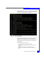
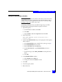
Legacy (x86 and most EM64T-based servers) boot BIOS configuration
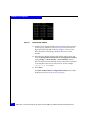
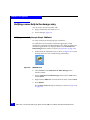
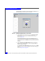
During POST, the QLogic banner will be displayed.
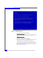
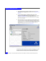
1. Press Ctrl+Q to enter the Configuration utility:
Figure 6
QLogic banner
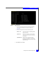
2. Select the adapter (enumerated by its I/O address) to be used for
boot.
Booting from the external storage array
29
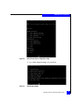
Installation and Configuration
If multiple adapters are installed, there will be multiple adapter
entries. The order of the adapter instances listed is the order they
will be scanned for a boot device; (note that this does not
necessarily correspond to PCI slot numbering), and press Enter.
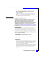
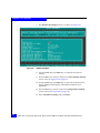
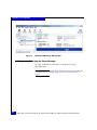
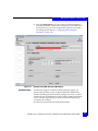
Figure 7
Main Fast!UTIL options window
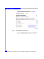
3. Select Configuration Settings from the main Fast!UTIL Options
dialog, and press Enter.
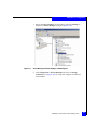
Figure 8
30
Configuration Settings window
EMC Host Connectivity with QLogic Fibre Channel HBAs and CNAs in the Windows Environment
Installation and Configuration
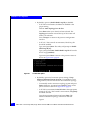
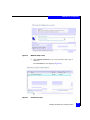
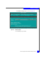
4. Select Adapter Settings from the Configuration Settings
window and press Enter.
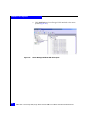
Figure 9
Adapter Settings window
5. The Host Adapter BIOS setting is Disabled by default; select this
setting and press Enter to enable Host Adapter BIOS.
Press Esc to return to the previous Configuration Settings (as
shown in Figure 8 on page 30).
Figure 10
Configuration Settings window
Booting from the external storage array
31
Installation and Configuration
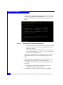
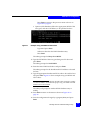
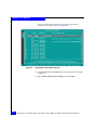
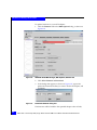
6. From the Configuration Settings dialog, select Selectable Boot
Settings and press Enter.
Figure 11
Selectable Boot Settings window
7. Selectable Boot is Disabled by default. Select this setting and
press Enter to enable Selectable Boot.
8. Scroll down to the (Primary) Boot Port Name, LUN: setting, and
press Enter.
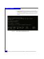
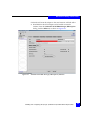
The Fast!UTIL will now scan for attached FC devices (as shown
in Figure 12 on page 33). If physical connectivity to the array is
setup properly via zoning, then the array port will be found after
this scan. Use the <PageUp> and <PageDown> keys to navigate
the list of target IDs for the array port being used for boot.
32
EMC Host Connectivity with QLogic Fibre Channel HBAs and CNAs in the Windows Environment
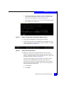
Installation and Configuration
Figure 12
Select Fibre Channel Device window
If no entries appear at any target IDs, verify the following:
• If multiple adapters are present, verify the adapter select in the
BIOS Utility is the same that currently provides the I/O path
to the storage (at this point, only one I/O path should be
configured to the boot LUN).
• For VNX series or CLARiiON systems, verify that the single
I/O path points to the SP which owns the boot LUN.
• For FC-SW environments, verify fabric zoning parameters, so
a single I/O path exists to the boot LUN. Refer to array
software documentation for details.
• Check physical FC connectivity between the adapter and
array (direct attach environment) or switch (FC-SW
environment).
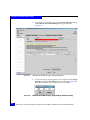
9. Select the array port to be used for boot, and press Enter.
If LUNs are allocated to the adapter (using LUN Masking
schemes, such as Access Logix™ or Volume Logix), they will be
presented at their LUN number.
Booting from the external storage array
33
Installation and Configuration
For example, Figure 13 shows that LUN 17 is masked to the
adapter. The LUN is available and is presented as "Supported" by
the BIOS.
Figure 13
Example of LUN 17 allocated to adapter
If no numbered entries appear in the above figure, verify the
following:
• For VNX series or CLARiiON systems, verify the single I/O
path points to the SP that owns the boot LUN.
• Verify array LUN masking settings are configured so this
adapter has visibility to the appropriate LUN. Refer to array
software documentation for details.
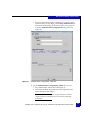
10. Select a supported LUN to use as the boot LUN (shown as LUN
17 in Figure 13) and press Enter.
The Selectable Boot Settings dialog is displayed (Figure 14 on
page 35) with the updated array port and LUN number as the
boot device.
34
EMC Host Connectivity with QLogic Fibre Channel HBAs and CNAs in the Windows Environment
Installation and Configuration
Figure 14
Selectable Boot Settings window
11. Press Esc to return to the previous Configuration Settings dialog.
12. Press Esc on the Configuration Settings dialog.
A dialog will appear to warn of a configuration change (as shown
in Figure 15).
Figure 15
Warning dialog
13. If the settings are correct, select Save changes to return to the
initial Fast!UTIL Options dialog.
Otherwise, press Esc to make additional changes, or select Do not
save changes and press Enter to return to the initial Fast!UTIL
Options window (as shown in Figure 16 on page 36).
Booting from the external storage array
35
Installation and Configuration
Figure 16
Fast!UTIL Options window
14. To exit the Fast!UTIL configuration utility, select Exit Fast!UTIL
and press Enter.
The system will now reboot.
During the subsequent reboot, the QLogic BIOS banner screen should
show the array and LUN specified as a boot-capable LUN (as shown
in Figure 17).
Figure 17
Typical QLogic BIOS banner screen
At this point, the OS installation can begin using this LUN as the boot
volume.
36
EMC Host Connectivity with QLogic Fibre Channel HBAs and CNAs in the Windows Environment
Installation and Configuration
Pre-configured
settings
The following parameters have been pre-configured in the EMC
NVRAM settings file. They are also configurable in the Host Adapter
Settings, Advanced Adapter Settings, and Extended Firmware
Settings menus. These menus and selections, when viewed in
SANSurfer v2.0.25 and later, may appear under different headings.
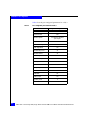
Table 2 lists the pre-configured parameters for 1 and 2 Gb/s.
Table 2
Pre-configured parameters for 1 and 2 Gb/s
Parameter
QLogic default setting
Data Rate
0 (1 Gb/s)
2 (Auto Select)
16
256
2
(Loop preferred,
otherwise point-to-point)
2
(Loop preferred,
otherwise point-to-point)
5
5
Enable LIP Full Login
Yes
Yes
Enable Target Reset
No
Yes
Port Down Retry Count
30
45
Link Down Timeout
30
45
Luns Per Target
8
256
Enabled
Disabled
Hard Loop ID
0
0
Descending Search LoopID
0
1
Operation Mode
0
0
Interrupt Delay Timer
0
0
Enable Interrupt (24xx
adapters)
No
No
Execution Throttle
Connection options (topology)
Loop Reset Delay
Adapter Hard Loop ID
EMC-approved setting
Booting from the external storage array
37
Installation and Configuration
Table 3 lists the pre-configured parameters for 4 Gb/s.
Table 3
Pre-configured parameters for 4 Gb/s
Parameter
EMC-approved setting for 4 Gb/s
Data Rate
Auto
Execution Throttle
256
Connection options
Loop preferred, otherwise
point-to-point
Loop Reset Delay
5
Enable LIP Full Login
Yes
Enable Target Reset
Yes
Port Down Retry Count
45
Link Down Timeout
45
LUNs Per Target
256
Enable Hard Loop
No
Hard Loop ID
0
Operation Mode
0
Interrupt Delay Timer
0
Frame Size
2048
Enable BIOS
No
Enable FC Tape
Yes
Login Retry Count
Enable Receive OoOFrame
38
8
Yes
EMC Host Connectivity with QLogic Fibre Channel HBAs and CNAs in the Windows Environment
Installation and Configuration
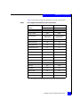
Table 4 lists the pre-configured parameters for 8 Gb/s and 16 Gb/s.
Table 4
Pre-configured parameters for 8 Gb/s and 16 Gb/s
EMC-approved setting
EMC-approved setting
Parameter
8 Gb/s
16 Gb/s
Data Rate
Auto
Auto
Execution Throttle
65535
65535
Connection options
Loop preferred, otherwise
point-to-point
Loop preferred, otherwise
point-to-point
Loop Reset Delay
5
5
Enable LIP Full Login
Yes
Yes
Enable Target Reset
Yes
Yes
Port Down Retry Count
45
30
Link Down Timeout
45
30
LUNs Per Target
256
128 a
Enable Hard Loop
No
No
Hard Loop ID
0
0
Operation Mode
0
0
Interrupt Delay Timer
0
0
Frame Size
2048
2048
Enable BIOS
No
No
Enable FC Tape
Yes
Yes
8
8
Yes
Yes
Login Retry Count
Enable Receive OoOFrame
a. This is a legacy setting for older storage arrays not supporting the Report LUNs command.
Booting from the external storage array
39
Installation and Configuration
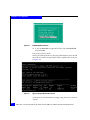
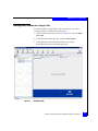
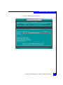
EFI (IA64 Itanium and some x64 servers) system firmware configuration
1. Prior to booting the server, ensure that media (USB memory
drive, CD-ROM, or floppy) which contains the QLogic EFI boot
code/utility is physically present in the system.
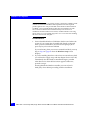
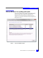
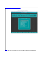
2. Following POST of the server, the Firmware Boot Manager
(similar to Figure 18) menu will be displayed.
Using the arrow keys, select the option for EFI Shell and press
Enter.
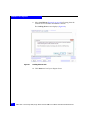
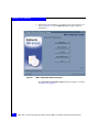
Figure 18
40
Firmware boot manager menu
EMC Host Connectivity with QLogic Fibre Channel HBAs and CNAs in the Windows Environment
Installation and Configuration
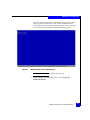
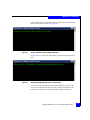
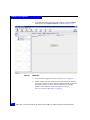
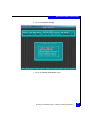
• The EFI shell will open, and the Device Mapping Table may be
listed by default (similar to Figure 19). If the Device Mapping
Table is not listed, type map and press Enter.
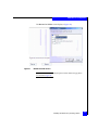
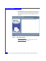
Figure 19
Device mapping table
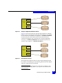
• The file systems available to the server are listed in the Device
Mapping Table, referenced by fsN, where N is a different
number for each available file system. The description next to
the fsN entry references the type of media on which the file
system resides.
In the example shown in Figure 19:
– fs0, fs1 and fs2 refer to memory ramdisks
– fs3 and fs4 refer to file systems on a CD inserted in the
CD-ROM
– fs5 refers to a file system on aUSB memory drive
– fs6 refers to an existing file system on an internal hard
drive.
Booting from the external storage array
41
Installation and Configuration
• The file system you select depends upon what media contains
the QLogic EFI boot code/utility. In this example, the QLogic
EFI boot code/utility resides on the USB memory drive.
3. Point the EFI shell to the proper file system by typing fsN: (where
N is the number which references the proper file system) followed
by Enter.
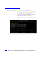
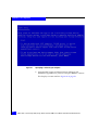
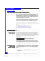
4. Before loading the QLogic EFI boot code/driver to the adapter(s),
ensure that any old EFI boot code loaded in the system has been
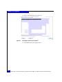
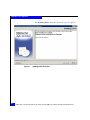
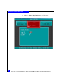
removed. Type drivers at the EFI shell prompt and press Enter.
a. Look for any driver listings that reference "QLogic Fibre
Channel Adapter," similar to the listing shown in Figure 20
Figure 20
Reference to QLogic Fibre Channel driver
b. If such a driver entry exists in the output, it should be
removed before installing the current driver. Make note of the
first two digits on the line which references the QLogic Fibre
Channel Driver ("60" in the example shown in Figure 20); this
is the "driver handle". Type unload <driver handle>.
For the example shown in Figure 20, unload 60 would be used
to remove the EFI driver. The system will prompt to "Unload
Protocol Image (y/n)?". Type y and press Enter. The existing
QLogic EFI driver will now be removed.
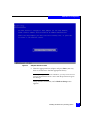
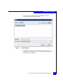
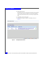
5. Type dir and press Enter to list the contents of the directory. If the
directory contents are not consistent with what you expect, and
do not appear to contain the QLogic boot code/utility, the file
system select may be incorrect.
6. Verify the proper file system has been selected. If the QLogic boot
code/utility resides in a subdirectory, type cd subdirectory and
press Enter.
42
EMC Host Connectivity with QLogic Fibre Channel HBAs and CNAs in the Windows Environment
Installation and Configuration
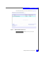
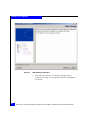
Figure 21
QLogic directory
• The directory listing should contain the QLogic EFI boot
code/utility downloaded to the media (as shown in
Figure 21).
• The files of importance will take the following form:
EFIutil.efi
QLogic EFI utility for updating adapter
driver/firmware.
qlxxxx.drv
EFI driver for QLogic (used by EFIutil
when the driver has not been flashed to
the adapter.)
qlxxxxxxx.bin
EFI boot driver image file package.
Flashed to the adapter to cause the EFI
boot driver to load automatically during
system start-up.
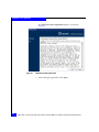
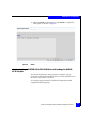
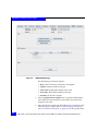
7. Type efiutil and press Enter.
Booting from the external storage array
43
Installation and Configuration
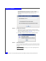
Figure 22
Fibre Channel Card Efi utility
The QLogic adapter(s) installed in the server will be listed (as shown
in Figure 22). Note the "firmware" version listed in the utility. If the
firmware is listed as a specific version (not a series of zeroes), and
"AUX" is not listed next to the firmware field at the top of the report
then the EFI driver and firmware have been loaded on the adapter(s);
proceed to the section immediately following Figure 25 on page 47.
If the firmware is listed as a series of zeros, and "AUX" is listed next to
the firmware field at the top of the report (as shown in Figure 22), this
indicates the EFI boot code has not yet been installed on the
adapter(s). Proceed as follows:
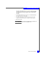
To install the EFI boot code driver and non-volatile RAM settings on the
adapter(s):
The EFI boot code driver must be loaded onto the adapter(s) in order
to be used by the EFI BIOS.
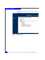
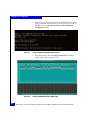
1. Type update.nsh <qxxxxxxx.bin>, inserting the name of the EFI
boot driver package (bin file). The update procedure with run and
appear similar to the output shown in Figure 22.
2. Press Enter.
44
EMC Host Connectivity with QLogic Fibre Channel HBAs and CNAs in the Windows Environment
Installation and Configuration
Figure 23
QLogic efiutil all upgrade
• The utility will upgrade EFI boot code drivers on all adapters
installed in the server and return to the EFI shell when
complete (as shown in Figure 23). If any errors are reported
during this process, verify that the correct EFI boot code driver
for your adapter has been copied to your installation media.
Booting from the external storage array
45
Installation and Configuration
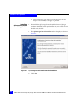
3. The appropriate NVRAM settings must now be loaded onto the
adapter(s). Type efiutil all nr=nvram23.dat (nvram23.dat is the
default NVRAM data file for QLA23xx-based adapters). Press
Enter.
Figure 24
Data loaded onto adapter(s) installed in server
• The NVRAM data will be loaded onto the adapter(s) installed
in the server (as shown in Figure 24), and return to the EFI
shell when complete.
• If any errors are reported during this process, verify that the
correct NVRAM data file (nvram23.dat) for your adapter has
copied to your installation media.
4. Type reset at the EFI shell prompt to reboot the server, allowing
the updated drivers, firmware, and NVRAM settings to take
effect.
5. Following the reboot, type fsN: (where N is the number which
references the proper file system, as described earlier).
6. Press Enter to access the file system containing the QLogic EFI
boot code.
• If the EFI boot code resides in a subdirectory, type cd
<subdirectory name> and press Enter.
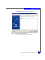
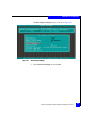
7. Type efiutil to start the QLogic EFI Utility and press Enter.
46
EMC Host Connectivity with QLogic Fibre Channel HBAs and CNAs in the Windows Environment
Installation and Configuration
• At this point, the QLogic adapter instances should be shown
with a specific firmware version, and "AUX" should not be
listed next to the firmware, as shown in Figure 25.
• At this point, the EFI drivers, firmware, and NVRAM settings
have loaded to the adapter(s).
Figure 25
QLogic adapter instances with specific firmware version
8. Type q and press Enter to exit the QLogic EFI Utility.
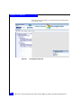
9. At the EFI shell prompt, type drivers and press Enter. Note the
entries that reference "QLogic Fibre Channel Adapter" are similar
to the listing shown in Figure 26.
Figure 26
QLogic Fibre Channel drivers
10. Make note of the first two digits (referred to as the "driver
handle") on the line that references the "QLogic Fibre Channel
Driver". If multiple adapters are installed in the server, there will
be multiple entries, as shown in Figure 26.
The order of the adapter instances listed is the order in which
they have been enumerated by the system. This does not
necessarily correspond to PCI slot numbering. In this example,
the two QLogic adapters installed in the server are using driver
handles 5F and 60, respectively.
a. Type drvcfg.
b. Press Enter.
Booting from the external storage array
47
Installation and Configuration
Figure 27
Driver handle numbers
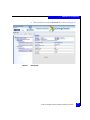
11. Find the driver handle numbers that correspond to those listed
for the QLogic adapters (as shown in Figure 27). Note the two
digits (proceeded by Ctrl, as shown in Figure 27) next to the
driver handles for the QLogic adapters. These are control
handles.
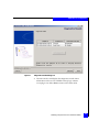
12. Determine the adapter instance that will be used for boot, and
enter the QLogic Fibre Channel Driver Configuration Utility by
typing drvcfg -s <driver handle> <control handle> (where
driver handle and control handle are the values that correspond
to the adapter instance to be used for boot. In this example,
"drvcfg -s 5f 62" is used.)
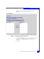
13. Press Enter.
The Fibre Channel Driver Configuration Utility menu will be
displayed (as shown in Figure 28 on page 49).
48
EMC Host Connectivity with QLogic Fibre Channel HBAs and CNAs in the Windows Environment
Installation and Configuration
Figure 28
Fibre Channel driver configuration utility
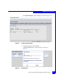
14. Type 1 (Edit Adapter Settings) and press Enter.
Figure 29
Edit adapter settings
Booting from the external storage array
49
Installation and Configuration
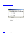
• By default, option 1 (Enable Hard Loop ID) is disabled.
– In FC-SW environments, the default of disabled is the
proper setting.
Select 2. Auto Topology: Pt to Pt first.
Press Enter when your choice has been selected. The
Topology information toward the top of the screen will
reflect your selection.
Press <Escape> to return to the previous configuration
window.
– In FC-AL/"direct attach" environments, Hard Loop ID
should be enabled.
Type 1 and press Enter. The utility will prompt to Enable
Hard Loop Id [n]?.
Type y and press Enter. Enable Hard Loop Id will now be
shown as [y] (enabled).
Type 0 and press Enter to return to the previous menu as
shown in Figure 28 on page 49.
Figure 30
Connection option
• By default, option 6 (Connection option) setting of Loop
Preferred, Otherwise Point To Point, is acceptable for most
configurations, and will auto-detect the connection topology.
– To manually set the connection topology, type 6 and press
Enter. Otherwise, type 0 and press Enter to return to the
previous menu as shown in Figure 28 on page 49.
– In FC-SW environments, Point To Point is the appropriate
setting. In FC-AL/"direct attach" environments, Loop Only
should be selected.
Type the appropriate selection and press Enter. The
selected connection topology will now be reflected.
Type 0.
50
EMC Host Connectivity with QLogic Fibre Channel HBAs and CNAs in the Windows Environment
Installation and Configuration
Press Enter to return to the previous menu as shown in
Figure 28 on page 49.
• Option 3 (Edit Database) allows the appropriate WWN of the
array port, and the LUN address, to be specified for boot.
Figure 31
Example array port WWN and LUN values
Type 3 and press Enter.
Select 0 to select the first WWN database entry.
Press Enter.
The utility prompts for Entry 0 Port WWN.
15. Type the full WWN of the array port being used for boot and
press Enter.
The utility prompts for Node WWN.
16. Enter the same WWN used above and press Enter.
The utility prompts for the hexadecimal LUN address to be used
for boot;
17. Type the appropriate hexadecimal LUN value to be used for boot
and press Enter. Figure 31 shows example array-port WWN and
LUN values.
Note: This utility does not explicitly check the values entered for validity,
care must be taken to ensure that the proper array port WWN and LUN
addresses have been entered.
The utility will prompt for another WWN database entry to
modify,
18. Press Enter to return to the menu as shown in Figure 28 on
page 49.
19. Save the configuration changes by typing 11 (Write) and press
Enter.
Booting from the external storage array
51
Installation and Configuration
The utility reports that it is done saving changes
20. Press any key to continue, and then 12 to exit the utility.
The system reports that options have been set, as shown in
Figure 32.
Figure 32
Options set
21. Press Enter to return to the EFI shell. Type reset to reboot the
server to enable the changes.
22. Following the reboot, open the EFI shell. The Device Mapping
Table may be listed by default (similar to Figure 19 on page 41).
a. If the Device Mapping Table is not listed, type map and press
Enter.
Figure 33
Example blkD as array port
b. Note any entries starting with blk (block-level devices, such as
volumes) which reference a Fibre interface (as shown in
Figure 33). The entry should list the array port WWN and
LUN address specified in the configuration utility. Figure 33
shows entry blkD as the array-port WWN and LUN specified
during configuration. This is the EFI entry that specifies the
specific array LUN to use for boot.
Note: The example shown in Figure 33 also shows BlkC as Lun0.
This is a Symmetrix®-based, read-only Volume Logix Database
device used for LUN masking and cannot be used for boot, even
though it is still detected by the QLogic EFI driver and is reported as
visible.
At this point, the OS installation can begin using this LUN as the boot
volume.
52
EMC Host Connectivity with QLogic Fibre Channel HBAs and CNAs in the Windows Environment
Installation and Configuration
Verifying array/LUN visibility for boot
Verification of the adapter ability to access the boot LUN, and boot
BIOS settings is recommended before installing the OS. Care must be
taken to ensure that only a single I/O path to the LUN exists when
installing the OS, a single adapter should have access to only a single
array port at this point. Selecting BIOS and Boot LUN configuration
settings vary with adapter vendor.
Refer to your array documentation for details on verifying adapter
connectivity.
Installing a RAMDISK under the EFI shell
Intel provides an EFI toolkit on the Intel website
http://www.intel.com/technology/efi. Included in the EFI toolkit is
the RAMDISK driver. To install the RAMDISK driver on your system,
copy the RAMDISK.EFI file to your USB flash drive.
Insert the USB flash drive in your EFI-based server’s USB port and
boot the server to the EFI shell. At the shell prompt, locate your USB
flash drive in the device mapping table. A line similar to the
following should be listed in the mapping table:
Fs0: Acpi (PNPOA03,0)/Pci (1D|1)Usb(1,0)/HD(Part1,Sig0D0C0B0A)
Switch to the USB flash drive by typing in the corresponding FS
number, followed by a colon (i.e., Fs0:) and press Enter.
At the FS prompt, type Load RAMDISK.EFI and press Enter. You
should see the message noting that the driver has loaded successfully.
To locate the new RAMDISK, type Exit and press Enter. From the
system Boot Manager menu, select EFI Shell to go back to the EFI
Shell. The device map should now show a new FS device as well as
the previous USB device.
Note: The order of the devices may have shifted with the discovery of the
RAMDISK.
Fs0: VenMsg(06ED4DD0-FF78-11D3-BDC4-00A0C94053D1)
Fs1: Acpi (PNP0A03,0)/Pci (1D|1)/Usb(1,0)/HD(Part1,Sig0D0C0B0A)
In the above example, the RAMDISK is now Fs0. Now you can copy
your driver files for your adapter to the RAMDISK. Switch to your
USB flash drive with the driver files and copy the files to the
Booting from the external storage array
53
Installation and Configuration
RAMDISK by using the copy command. As with DOS, the copy
command can use an asterisk to grab multiple files, (i.e., Copy *.*
fs0:).
Once the files are copied to the RAMDISK, you may proceed to install
Windows.
Note: If the server is rebooted at any time, this procedure will need to be
repeated as the RAMDISK is deleted during a reboot.
54
EMC Host Connectivity with QLogic Fibre Channel HBAs and CNAs in the Windows Environment
Installation and Configuration
Installing the Windows operating system
This section provides procedures for installing Windows 2000/2003
and Windows 2008 operating systems.
◆
“Windows 2000/2003 internal or external boot disk installation,”
next
◆
“Windows 2008 internal or external boot disk installation” on
page 63
Windows 2000/2003 internal or external boot disk installation
This section is a step-by-step procedure for installing Windows
2000/2003 Operating System to either an internal or external boot
device.
After you have your adapter(s) installed in your server, and
configured for external boot if necessary, the next step is to install the
Windows operating system. If you intend to boot to an external
device please refer to “Booting from the external storage array” on
page 26 for setting the boot BIOS for external boot and selecting the
external boot lun. If your system is EFI-based refer to “Installing a
RAMDISK under the EFI shell” on page 53. Also refer to your
server’s documentation for preparing your server for external boot.
QLogic provides a minimal driver installation kit for boot from SAN
installations. This kit includes an adapter driver that is small enough
to fit on a floppy disk. Be sure to download the correct kit in order to
install Windows on your external boot LUN.
Note: If you intend to boot to an external disk, only present the LUN that you
intend to boot from. All additional luns can be added after the installation.
This will eliminate any confusion on selecting the correct partition for
installation and eliminates any problems that the Operating System could
encounter on reboot during the installation. Also confirm there is only one
path to the storage array. Having more than one path can cause the operating
system to fail during the installation.
You need the following materials to install Windows:
◆
A Windows CD-ROM for the Windows version you wish to
install
◆
AN EMC-approved boot driver on diskette, or an EFI RAMDisk if
it is an EFI based install
Installing the Windows operating system
55
Installation and Configuration
Note: Driver version 9.1.7.16 and later requires a minimum of Windows 2003
with Service Pack 2 and STORPort hotfix Q950903. Since these required
patches/QFEs do not come pre-installed on the Windows 2003 installation
CD-ROM, you must install Windows 2003 using an installation CD with
Service Pack 2 included in the installation kit. If you do not have an
installation CD that includes Service Pack 2, install the Windows OS using
QLogic driver v9.1.4.15 and then upgrade to v9.1.7.16 or later after installing
the correct Service Pack and QFE.
To install Windows:
1. Insert a bootable Windows CD-ROM in the drive and reboot the
system. If your system has a bootable disk already configured
from a previous installation, the software will prompt you to
press any key to boot from CD-ROM.
If you are booting from your server's internal hard disk, you may
skip to Step 6 on page 60 when the Windows Setup screen
displays.
2. If you are installing Windows to boot from an external array disk,
you will need to supply setup with the adapter driver. To do this,
immediately after the Windows installation begins, press F6
when directed or when the blue screen appears. Otherwise,
proceed to step 6.
Pressing F6 tells the Windows installer you want to load a
third-party driver before proceeding with the installation.
56
EMC Host Connectivity with QLogic Fibre Channel HBAs and CNAs in the Windows Environment
Installation and Configuration
If you do not press F6 in time to add the drivers, restart the server
and try again. You will know if you missed the F6 function to
install third-party drivers when the setup returns with a warning
that it cannot find a partition to load the operating system
Figure 34
Windows Setup screen with F6 prompt
Note: Windows 2000 does not display the F6 prompt.
3. When prompted for additional drivers, select S (Specify
Additional Device).
Installing the Windows operating system
57
Installation and Configuration
Figure 35
Specifying a driver for your adapter
4. Insert the EMC-approved adapter Drivers diskette or EFI
RAMDisk if applicable for your OS. Then press Enter to continue.
This displays a screen similar to Figure 36 on page 59.
58
EMC Host Connectivity with QLogic Fibre Channel HBAs and CNAs in the Windows Environment
Installation and Configuration
Figure 36
Adapter selection screen
5. Select the appropriate boot adapter and press Enter. (You may
have to scroll down to find the appropriate driver.)
Note: Depending on the version of Windows, you may receive an error
message that the default driver is newer than the provided one. Ignore
this message.
Setup continues to load files, and a Windows Setup screen
appears.
Installing the Windows operating system
59
Installation and Configuration
Figure 37
Windows setup screen
6. Press Enter to begin the setup procedure.
Note: If you are installing Windows on a newly created LUN, you may
receive a message that your boot disk is new or erased. Press C to
continue.
A Windows Licensing Agreement appears.
7. Read the license agreement. (Press Pg Dn as necessary to scroll
through the text.) To accept the agreement, press F8.
Setup inspects your computer's hardware configuration. The
setup screen displays disk partition information (if your system
already contains partitions), or lets you create a new partition.
(Refer to Figure 38 on page 61.)
60
EMC Host Connectivity with QLogic Fibre Channel HBAs and CNAs in the Windows Environment
Installation and Configuration
Note: The Windows 2000 boot LUN cannot exceed 7.8 GB unless INT-13
extensions are enabled in the adapter BIOS. (Refer to Microsoft
Knowledge Base article Q240672.)
Figure 38
Existing partitions
Installing the Windows operating system
61
Installation and Configuration
8. If you are installing an operating system for the first time,
highlight Unpartitioned Space on the adapter. Then:
• Press Enter to use the entire disk as one partition
or
• Press C to create a custom partition, and then specify the
partition size
If the new disk is displayed as Unformatted or Damaged you
must delete the partition before continuing. To do this, press D,
and follow the onscreen delete instructions. After you delete the
partition, the disk will then appear as Unpartitioned Space.
If you are reinstalling Windows, the setup software prompts you
to overwrite or upgrade:
• To overwrite, press Esc and follow instructions.
• To upgrade, press Enter.
• To create a new hard-disk partition, you must first delete the
existing partition, and then create a new one. To do so, select
the partition you want to delete, press D, and then follow the
onscreen instructions to complete the deletion of the partition.
Once the system deletes the partition, you can press C to
create a new one.)
9. The setup software prompts you to specify the file system format
for the partition. Select NTFS file system format (which is
suitable for most sites) and press Enter, unless you have other
specific requirements.
Note: For background information on the choice of the NTFS file system,
refer to Microsoft Knowledge Base Article 184006.
Setup formats the partition, copies the Windows system files to
the partition, and starts rebooting the server.
10. When prompted, remove the diskette and CD-ROM.
11. If your system prompts you to press any key to boot from
CD-ROM, do not press a key. Instead, allow the system to boot
from the array (if external) or the local disk (if internal). After
booting, the system continues installation, displays the Windows
banner, and begins auto detection of mass-storage devices and
adapters.
62
EMC Host Connectivity with QLogic Fibre Channel HBAs and CNAs in the Windows Environment
Installation and Configuration
12. Follow the onscreen instructions to complete the installation.
When the Completing the Windows Setup Wizard screen
appears, click Finish.
13. Install the latest EMC-approved Windows Service Pack and/or
OS patches or updates. Follow the procedures in the Microsoft
documentation that accompanies the updates.
Windows 2008 internal or external boot disk installation
This section is a step-by-step procedure for installing a Windows
operating system to either an internal or external boot device.
After you have your adapter(s) installed in your server, and
configured for external boot if necessary, the next step is to install the
Windows operating system. If you intend to boot to an external
device, refer to “Booting from the external storage array” on page 26
for setting the boot BIOS for external boot and selecting the external
boot LUN.
Note: If you intend to boot to an external disk, present only the LUN from
which you intend to boot. All additional LUNs can be added after the
installation. This will eliminate confusion on selecting the correct partition
for installation and eliminates any problems that the operating system could
encounter on reboot during the installation. Also confirm there is only one
path to the storage array. Having more that one path can cause the operating
system to fail during the installation.
To install Windows, you need the following materials:
◆
A Windows DVD-ROM for the Windows 2008 you wish to install
◆
An EMC-approved adapter driver jump-drive (USB) for
Windows
To install Windows:
1. Insert a bootable Windows DVD-ROM into the drive and reboot
the system. If your system has a bootable disk already configured
from a previous installation, the software will prompt you to
press any key to boot from DVD-ROM.
2. If you are installing Windows to boot from an external array disk,
you will need to supply setup with the adapter driver in a USB
jump-drive and insert it in your server prior to the Windows
installation.
Installing the Windows operating system
63
Installation and Configuration
The Windows Boot Manager screen displays (Figure 39).
Figure 39
Windows Boot Manager
3. Press Enter to continue the installation.
The Windows Setup screen displays (Figure 40).
Figure 40
64
Windows Setup screen
EMC Host Connectivity with QLogic Fibre Channel HBAs and CNAs in the Windows Environment
Installation and Configuration
4. Click Next to continue to the Windows Install screen (Figure 41).
Figure 41
Windows Install screen
5. Click Install now to continue to the Windows operating system
selection screen (Figure 42).
Figure 42
Windows operating system selection screen
Installing the Windows operating system
65
Installation and Configuration
6. Choose your operating system type and click Next to continue to
the Microsoft Software License Terms screen (Figure 43).
Figure 43
Microsoft Software License Terms screen
7. Check the I accept the license terms checkbox and click Next to
continue to the Windows setup screen (Figure 44 on page 67).
66
EMC Host Connectivity with QLogic Fibre Channel HBAs and CNAs in the Windows Environment
Installation and Configuration
.
Figure 44
Windows setup screen
8. Click Custom (advance) if you want to install a clean copy of
Windows.
The Load driver screen displays (Figure 45).
Figure 45
Load driver screen
Installing the Windows operating system
67
Installation and Configuration
9. Select Load Driver (Figure 45 on page 67) if booting from the
external device and then click Next to continue.
The Loading driver screen displays (Figure 46).
Figure 46
Loading driver screen
10. Click Browse to load your adapter driver.
68
EMC Host Connectivity with QLogic Fibre Channel HBAs and CNAs in the Windows Environment
Installation and Configuration
The Browse for Folder screen displays (Figure 47).
Figure 47
Browse for Folder screen
Note: You would see your USB jump-drive rather than the Floppy Drive
A as shown in Figure 47.
Installing the Windows operating system
69
Installation and Configuration
11. Select your USB jump-drive (Figure 48).
Figure 48
Specifying a driver for your adapter
12. Click Next to load your adapter driver.
70
EMC Host Connectivity with QLogic Fibre Channel HBAs and CNAs in the Windows Environment
Installation and Configuration
You will be asked where you want to install Windows (Figure 49).
Figure 49
Windows installation prompt screen
Note: Select Drive Options (advance) to format your file system.
Installing the Windows operating system
71
Installation and Configuration
After the adapter driver is loaded, the Install Windows screen
displays (Figure 50).
Figure 50
Install Windows screen
13. Click Next to begin the Windows installation.
Setup will copy the Windows system files to the partition and
start rebooting the server.
14. Do not press a key if your system prompts you to "press any key
to boot from DVD-ROM." Instead, allow the system to boot from
the array (if external) or the local disk (if internal). After booting,
the system continues installation, displays the Windows banner,
and begins auto detection of mass-storage devices and adapters.
15. Follow the on-screen instructions to complete the installation.
72
EMC Host Connectivity with QLogic Fibre Channel HBAs and CNAs in the Windows Environment
Installation and Configuration
Windows 2008 Server Core operating system option
Windows Server 2008 includes a variation of an installation called a
Server Core. Server Core is a "scaled-back" installation where no
Windows Explorer shell is installed. All configuration and
maintenance is done either through the command line interface
windows or by connecting to the machine remotely using Microsoft
Management Console.
Figure 51
Server Core installation example
Windows 2008 Server Core operating system option
73
Installation and Configuration
Limitations
Since Server Core is a special installation of Windows Server 2008, the
following limitations exist:
◆
You cannot upgrade from a previous version of the Windows
Server operating system to a Server Core installation. Only a
clean installation is supported.
◆
You cannot upgrade from a full installation of Windows Server
2008 to a Server Core installation. Only a clean installation is
supported.
◆
You cannot upgrade from a Server Core installation to a full
installation of Windows Server 2008. If you need the Windows
user interface or a server role that is not supported in a Server
Core installation, you must install a full installation of Windows
Server 2008.
EMC support
EMC supports the use of Server Core for attach to EMC storage
arrays. The currently supported adapter drivers/firmware/BIOS and
adapter driver utilities are approved for use with this version of
Windows 2008. Use of the QLogic SANsurfer driver install wizard
(executable driver package), as shown in Figure 52, works exactly as
it will on a standard Windows 2008 installation, but the wizard must
be started from the command prompt.
Figure 52
74
QLogic SANsurfer driver install wizard
EMC Host Connectivity with QLogic Fibre Channel HBAs and CNAs in the Windows Environment
Installation and Configuration
Likewise, the QLogic SANsurfer adapter utility must be started from
the command line, as shown in Figure 53.
Figure 53
QLogic SANsurfer adapter utility installation
Figure 54 shows SANsurfer utility being started from the command
line.
Figure 54
Starting SANsurfer utility from the command line
Once the command has been issued, the installation wizard for the
driver and SANsurfer kits will run with a normal installation GUI
interface as it would on a standard Windows 2008 installation.
Windows 2008 Server Core operating system option
75
Installation and Configuration
Installing adapter driver and software utilities
To use EMC storage array disks with a Windows 2000, 2003, or 2008
host, you need a Fibre Channel host adapter driver. The driver and
related utilities must be installed and configured before Windows can
access the EMC disks. This driver can be installed using the QLogic
SANsurfer Install Wizard for Windows.
For Windows 2003, EMC supports both the STORPort driver class
and the SCSIPort driver class. Windows 2000 uses only the SCSIPort
driver class. Windows 2008 uses only the STORPort driver class.
Three sections are outlined on the following pages to help with
installation and configuration of your adapter drivers and associated
utilities:
◆
“Pre-installation guidelines” , next
◆
“Driver installation/upgrade” on page 77
◆
“Post-installation procedures” on page 86
Pre-installation guidelines
Required Windows
STORPort updates
Currently, the shipping version of Windows requires post-RTM hot
fixes to resolve some known issues. For all Windows STORPort
installations, you must obtain the current Microsoft QFE hotfix listed
in the EMC Support Matrix with the adapter driver revisions.
IMPORTANT
Install this QFE before installing the adapter driver.
Users planning to upgrade to the latest service pack for Windows
should upgrade their adapter drivers to the latest supported version
prior to installing the service pack. The Windows Service Packs do
not contain the latest EMC-approved driver revisions. Always
consult the EMC Support Matrix for the most up-to-date information.
Obtaining the QLogic
SANsurfer Install
Wizard for Windows
The SANsurfer Install Wizard for Windows is available on CD-ROM
or downloaded from the QLogic website. To download from the
website:
1. If downloading from the QLogic website, first create a directory
that will be used to save the SANsurfer Install Wizard for
Windows file.
76
EMC Host Connectivity with QLogic Fibre Channel HBAs and CNAs in the Windows Environment
Installation and Configuration
2. Go to http://www.qlogic.com.
3. Select Downloads at the top of the page.
4. Select EMC under OEM models.
5. Select the link containing your EMC storage.
6. Select the adapter you installed in your system and download the
SANsurfer Install Wizard for Windows.
Driver installation/upgrade
1. Install the SANsurfer Install Wizard for Windows Kit CD-ROM to
start the SANsurfer HBA Install Wizard. If you downloaded the
kit to your hard drive locate and double-click the file. The wizard,
shown in Figure 55, will extract needed files from the installation
kit.
Figure 55
SANsurfer Driver Install Wizard for Windows
Installing adapter driver and software utilities
77
Installation and Configuration
2. After the wizard initializes, you will be given several options, as
shown in Figure 56. Click Update Driver to begin the driver
installation.
Figure 56
HBA Configuration Update dialog box
The Select Driver Installation type dialog box appears, as shown
in Figure 57 on page 79.
78
EMC Host Connectivity with QLogic Fibre Channel HBAs and CNAs in the Windows Environment
Installation and Configuration
3. Select I want to install the driver automatically.
Figure 57
Select Driver Installation Type dialog box
Note: If you are upgrading your adapter driver, you will taken to the
HBA Configuration Update screen shown in Figure 56 on page 78. At
this point, click the Update Driver button. You will be taken to the Select
Driver Installation Type screen shown in Figure 57 on page 79. Select the
driver you wish to install, and proceed with the procedure at Step 4 on
page 81.
The Select a Driver Location dialog box appears, as shown in
Figure 58 on page 80.
Installing adapter driver and software utilities
79
Installation and Configuration
Figure 58
SANsurfer driver location dialog box
This window presents three choices:
• Default Driver
This is the default selection. This selection will use the driver
located on the CD-ROM or the SANsurfer Install Wizard for
Windows file. Use this option if you downloaded the kit from
the QLogic website.
• From the QLogic website
The selection will automatically search the QLogic website for
the latest driver. An Internet connection is required. Use this
selection if you are upgrading your adapter drivers to a newer
version.
• Browse
Use this option if you previously downloaded the driver file
and stored it on your hard drive.
80
EMC Host Connectivity with QLogic Fibre Channel HBAs and CNAs in the Windows Environment
Installation and Configuration
4. Click Next to continue. A message similar to the following will
appear:
Figure 59
SANsurfer installation with version number
Installing adapter driver and software utilities
81
Installation and Configuration
5. The wizard display a summary screen, as shown in Figure 60,
describing the actions it will take during the driver installation
and the version of driver to be installed. Note that the server may
require a reboot after the driver load. Click Next to start the
installation.
Figure 60
Updating Driver dialog box
Note: Depending on the number of installed adapters, the driver
installation may take a couple of minutes.
82
EMC Host Connectivity with QLogic Fibre Channel HBAs and CNAs in the Windows Environment
Installation and Configuration
6. If this is not a new installation, the message in Figure 61 may
appear. Check the Stop QLogic Management Suite Java Agent
Service checkbox and click Next.
Figure 61
SANsurfer Java agent service message
Installing adapter driver and software utilities
83
Installation and Configuration
The Installing Driver dialog box, shown in Figure 62, appears.
Figure 62
84
Installing Driver dialog box
EMC Host Connectivity with QLogic Fibre Channel HBAs and CNAs in the Windows Environment
Installation and Configuration
7. When the driver installation completes, the Driver installed
successfully message appears, as shown in Figure 63. Click Next
to continue.
Figure 63
Driver Update Completed dialog box
8. If a reboot is required, the wizard will give you the option of
rebooting,or canceling the reboot and continuing with the wizard.
If you cancel the reboot, click Next to continue back to the
configuration update screen.
Installing adapter driver and software utilities
85
Installation and Configuration
9. The HBA Configuration Update screen, shown in Figure 65, will
appear after the driver installation is complete. From here, you
may perform diagnostic procedures or other post-installation
tasks. If you are finished with your adapter update, click Quit.
Figure 64
HBA Configuration update dialog box
Post-installation procedures
Diagnostics
86
1. From the HBA Configuration Update screen, click Perform
Diagnostics (refer to Figure 64).The SANsurferHBA Install
Wizard window will appear, as shown in Figure 65 on page 87.
EMC Host Connectivity with QLogic Fibre Channel HBAs and CNAs in the Windows Environment
Installation and Configuration
Figure 65
Select HBA dialog box
2. Select the adapters to be tested and select Next.
Installing adapter driver and software utilities
87
Installation and Configuration
d
Figure 66
Attach Storage dialog box
3. Ensure that the adapters you selected for diagnostics are
connected to storage or to a loopback terminator. Click Next to
run the test.
88
EMC Host Connectivity with QLogic Fibre Channel HBAs and CNAs in the Windows Environment
Installation and Configuration
Figure 67
Diagnostics results dialog box
4. The next window will display the diagnostics results. More
information on this tool is available at the QLogic website
www.qlogic.com. Select Next to return to the main menu.
Installing adapter driver and software utilities
89
Installation and Configuration
Show SAN
Figure 68 shows the SAN tree.
Figure 68
Show SAN tree
The Show SAN feature is useful for verifying connectivity to the
storage array.
90
EMC Host Connectivity with QLogic Fibre Channel HBAs and CNAs in the Windows Environment
Installation and Configuration
FCoE converged network adapter (CNA) procedures
This section provides the following information on FCoE converged
network adapters:
◆
“Overview” on page 91
◆
“Installing Fibre Channel BIOS and firmware on a QLogic CNA”
on page 93
◆
“Installing Menlo firmware on a QLogic CNA” on page 97
◆
“Installing or upgrading the driver and utilities on a QLogic
QLE8242 CNA” on page 101
◆
“Updating adapter firmware on a QLogic QLE8242 CNA” on
page 105
◆
“Configuring QLogic FAST!UTIL 10 GbE iSCSI BIOS/boot LUN
settings for QLE8242 iSCSI adapters” on page 117
Overview
FCoE converged network adapters (CNAs) are similar to Fibre
Channel adapters in that they require drivers in order to function in a
Windows server. However, because of its ability to converge both
Fibre Channel and Ethernet traffic over a single physical link, the
adapter will appear to the Windows server as two different pieces of
hardware. When viewing the Windows Device Manager, you will see
both a QLogic Fibre Channel adapter as well as an Intel 10 Gigabit
network adapter available in the system, as shown in Figure 69 on
page 92.
FCoE converged network adapter (CNA) procedures
91
Installation and Configuration
Figure 69
Device Manager
Both of these hardware devices require a driver in order to function.
For the Fibre Channel adapter, the same procedure that is used to
install drivers on standard Fibre Channel adapters, described in
“Installing adapter driver and software utilities” on page 76, can be
used.
For the Intel 82598 10 Gigabit Ethernet Controller, visit
http://www.intel.com for drivers and information on driver
installation for this network adapter.
FCoE adapters also require BUIOS and firmware code for the Fibre
Channel adapter, as well as for the encapsulation ASIC known as the
Menlo chip. To update these BIOS and firmware versions, the QLogic
SANsurfer utility must be used. The minimum SANsurfer version for
92
EMC Host Connectivity with QLogic Fibre Channel HBAs and CNAs in the Windows Environment
Installation and Configuration
use with FCoE adapters is v5.0.1 build 34 and is packaged with the
EMC-approved driver for the FCoE adapter.
Installing Fibre Channel BIOS and firmware on a QLogic CNA
To install the Fibre Channel firmware on your FCoE converged
network adapter, start the SANsurfer utility, shown in Figure 70, and
then follow these steps:
1. In the left pane of the utility, you will see the CNA listed under
your server host name. Click open the CNA and click on the
appropriate port number in order to view all of the possible
options in the right pane of the utility.
Figure 70
SANsurfer utility
FCoE converged network adapter (CNA) procedures
93
Installation and Configuration
2. Click Utilities in the right pane of the SANsurfer utility.
3. Under the Utilities tab, shown in Figure 71, you will see several
sections that allow you to update the CNA flash, HBA
parameters, and the CNA driver. To update the Fibre Channel
BIOS and firmware of the adapter, click Update Entire Image.
Figure 71
Utilities tab
4. An Open dialog box displays, as shown in Figure 72 on page 95.
Browse to the location of your firmware file that you wish to load.
This file could be included on EMC-Approved installation media,
or can be downloaded from the QLogic website as described
“Downloading latest QLogic drivers/firmware/BIOS files” on
page 16.
94
EMC Host Connectivity with QLogic Fibre Channel HBAs and CNAs in the Windows Environment
Installation and Configuration
Note: : This file, known as the multiboot image, contains the BIOS,
FCode, and firmware for the adapter. This process will flash all of this
code to the adapter simultaneously.
Figure 72
Open dialog box
5. After locating your firmware file, click Open.
6. Depending on whether you have done other configuration
changes to your adapter, you may be asked for the password to
make changes, as shown in Figure 73 on page 96.
FCoE converged network adapter (CNA) procedures
95
Installation and Configuration
The default password is config and if you leave the save password
for the current session box checked, you will not be required to
reenter this password later unless you close SANsurfer.
Figure 73
Security Check dialog box
7. SANsurfer may appear to be unresponsive while the adapter
flash memory is being updated. A message will appear when the
process is complete, as shown in Figure 74.
Figure 74
Flash Update dialog box
8. Click OK to complete the BIOS/firmware update procedure.
If you have other CNAs installed in your server, or second paths on
the same CNA, select them in the left pane of the SANsurfer utility
and follow this procedure for each CNA you need to update.
96
EMC Host Connectivity with QLogic Fibre Channel HBAs and CNAs in the Windows Environment
Installation and Configuration
Installing Menlo firmware on a QLogic CNA
To install the Menlo encapsulation ASIC firmware on your FCoE
converged network adapter, follow these steps.
1. Start the SANsurfer utility, as shown in Figure 75, and click Open
your CNA.
2. In the left panel, under the CNA, click the FCoE Engine.
3. In the right pane of the SANsurfer utility, you will see
information about the CNA Menlo firmware.
Figure 75
SANsurfer utility
FCoE converged network adapter (CNA) procedures
97
Installation and Configuration
4. To update the Menlo firmware of the adapter, click the Utilities
tab and then click Update Firmware, as shown in Figure 76.
Figure 76
Utilities tab
5. A new window appears, as shown in Figure 77 on page 99.
6. In this window, browse to the location of the firmware file that
you wish to load. This file could be included on EMC-Approved
installation media, or can be downloaded from the QLogic
website as described in “Downloading latest QLogic
drivers/firmware/BIOS files” on page 16.
98
EMC Host Connectivity with QLogic Fibre Channel HBAs and CNAs in the Windows Environment
Installation and Configuration
7. After locating your firmware file, click Open to flash the
firmware file to the CNA Menlo chip.
Figure 77
Open dialog box
8. Depending on whether you have done other configuration
changes to your adapter, you may see a dialog box asking for the
password to make changes.
FCoE converged network adapter (CNA) procedures
99
Installation and Configuration
The default password is config and if you leave the Save
password for the current session box checked, you will not be
required to reenter this password later unless you close
SANsurfer.
Figure 78
Security Check dialog box
9. SANsurfer may appear to be unresponsive while the adapter
flash memory is being updated. A message will appear when the
process is complete, as shown in Figure 79.
10. Click OK to complete the BIOS/firmware update procedure.
Figure 79
Flash update dialog box
If you have other CNAs installed in your server, select them in the left
pane of the utility and follow this procedure for each CNA you need
to update.
Note: EMC recommends rebooting your server after completing firmware
updates to your adapter.
100
EMC Host Connectivity with QLogic Fibre Channel HBAs and CNAs in the Windows Environment
Installation and Configuration
Installing or upgrading the driver and utilities on a QLogic QLE8242 CNA
To install or upgrade the driver and utilities on a QLogic QLE8242
CNA, complete the following steps.
1. Download the driver kit installer from the QLogic website in the
EMC section and install it on your system. If you have
downloaded the kit to your hard drive, locate then double-click
the file.
The QConverged Console Driver Install Wizard displays, as
shown in Figure 80.
Figure 80
QConverged Console Driver Install Wizard
2. Click Next to start the installation.
FCoE converged network adapter (CNA) procedures
101
Installation and Configuration
The End User License Agreement displays, as shown in
Figure 81.
Figure 81
End User License Agreement
3. After reading the agreement, click Agree.
102
EMC Host Connectivity with QLogic Fibre Channel HBAs and CNAs in the Windows Environment
Installation and Configuration
The next window displays installation options, as shown in
Figure 82.
Figure 82
Installation options
4. Select Install Drivers and Applications and click Install.
FCoE converged network adapter (CNA) procedures
103
Installation and Configuration
The next window displays the installation progress, as shown in
Figure 83.
Figure 83
104
Installation progress
EMC Host Connectivity with QLogic Fibre Channel HBAs and CNAs in the Windows Environment
Installation and Configuration
5. After you receive the "Your installation is complete" message, as
shown in Figure 84, click Finish.
Figure 84
Installation complete
Updating adapter firmware on a QLogic QLE8242 CNA
Before updating adapter firmware, note the following:
◆
The QLogic driver must be installed.
◆
The QConvergeConsole GUI application must be installed.
◆
Before you can perform a firmware update, the firmware file
must be downloaded from the QLogic website and extracted to a
folder on a local drive. This file could be included on
EMC-approved installation media, or downloaded from the
QLogic website.
◆
If the adapter is already connected to a boot device, the system
must be in a state in which this type of maintenance can be.
• I/O activity on the bus has been stopped.
FCoE converged network adapter (CNA) procedures
105
Installation and Configuration
• Cluster software, or any other software that relies on the
adapter to be available, is stopped or paused.
Installing
QConvergeConsole
GUI application
1. Download the QConvergeConsole installer from the QLogic
website in the EMC section and install it on your system. If you
have downloaded the kit to your hard drive, locate then
double-click, the file.
1. The QConvergeConsole Installer window displays, as shown in
Figure 85.
Figure 85
QConvergeConsole Installer Introduction window
2. Click Next.
106
EMC Host Connectivity with QLogic Fibre Channel HBAs and CNAs in the Windows Environment
Installation and Configuration
3. The Tomcat Port Number Setup window displays, as shown in
Figure 86.
Figure 86
Tomcat Port Number Setup window
4. Accept the default port number and click Next.
FCoE converged network adapter (CNA) procedures
107
Installation and Configuration
The Pre-Installation Summary window displays, as shown in
Figure 87.
Figure 87
Pre-Installation Summary window
5. Review the summary and click Install.
A message asks you whether to enable SSL feature, as shown in
Figure 88.
Figure 88
108
Enable SSL feature dialog box
EMC Host Connectivity with QLogic Fibre Channel HBAs and CNAs in the Windows Environment
Installation and Configuration
6. Click Yes to enable SSL and the installation starts.
7. When the Installation Complete window displays as shown in
Figure 89, click Done to complete the installation.
Figure 89
Updating firmware
Installation Complete window
To update the Fibre Channel firmware on your FCoE converged
network adapter, complete the following steps.
1. Start the QConvergeConsole GUI, as shown in Figure 90.
FCoE converged network adapter (CNA) procedures
109
Installation and Configuration
In the left pane of the utility, you will see the CNA listed under
your server name.
Figure 90
110
QConvergeConsole GUI
EMC Host Connectivity with QLogic Fibre Channel HBAs and CNAs in the Windows Environment
Installation and Configuration
2. Click on the Port to view the Port Info tab, as shown in Figure 91.
Figure 91
Port Info tab
FCoE converged network adapter (CNA) procedures
111
Installation and Configuration
3. Click Wizards and select Flash Update Wizard (SAN) from the
drop-down menu, as shown in Figure 92.
Figure 92
112
Wizards > Flash Update Wizard (SAN)
EMC Host Connectivity with QLogic Fibre Channel HBAs and CNAs in the Windows Environment
Installation and Configuration
This will start the SAN Flash Update Wizard, as shown in
Figure 93.
Figure 93
SAN Flash Update Wizard, Add localhost
4. In the Connected Host(s): column, select localhost and click Add
> to move it to the Selected Host(s): column, as shown in
Figure 93.
5. Click Next.
FCoE converged network adapter (CNA) procedures
113
Installation and Configuration
6. The File Selection window displays, as shown in Figure 94.
Figure 94
File Selection window
7. Click Select Image File.
A pop-up window displays, as shown in Figure 94, that lets you
locate and upload the firmware file.
8. After you select the image file, click Send on the pop-up window.
114
EMC Host Connectivity with QLogic Fibre Channel HBAs and CNAs in the Windows Environment
Installation and Configuration
The Confirm Changes window displays, as shown in Figure 95.
Figure 95
Confirm Changes window
9. Confirm the changes and click Next.
A Security Check pop-up window displays as shown in
Figure 96.
Figure 96
Security Check
FCoE converged network adapter (CNA) procedures
115
Installation and Configuration
10. Type in the password.
The default password is config and if you leave the save password
for the current session box checked, you will not be required to
reenter this password later unless you close QConvergeConsole
GUI.
11. Click OK to start the flash update.
12. When the flash update completes, click Next, as shown in
Figure 97.
Figure 97
116
Flash Update Status window
EMC Host Connectivity with QLogic Fibre Channel HBAs and CNAs in the Windows Environment
Installation and Configuration
13. When the Finish window displays, click Finish to complete the
flash update, as shown in Figure 98.
Figure 98
Finish
Configuring QLogic FAST!UTIL 10 GbE iSCSI BIOS/boot LUN settings for QLE8242
iSCSI adapters
This section describes the steps required to configure a QLogic
Fast!UTIL 10 GbE iSCSI boot BIOS to allow an array-attached LUN to
be used as a boot disk for the server.
To configure QLogic Fast!UTIL 10 GbE iSCSI adapter boot BIOS,
complete the following steps.
FCoE converged network adapter (CNA) procedures
117
Installation and Configuration
1. When the QLogic Fast!UTIL 10 GbE iSCSI BIOS banner displays
during power-on self-test (POST), as shown in Figure 99, press
Ctrl Q to enter the QLogic Fast!UTIL 10 GbE iSCSI BIOS
Configuration utility.
Figure 99
QLogic Fast!UTIL 10 GbE iSCSI BIOS banner
2. The utility opens to the main QLogic Fast!UTIL iSCSI Select
Utility page, as shown in Figure 100.
Figure 100
118
QLogic Fast!UTIL iSCSI Select Utility page
EMC Host Connectivity with QLogic Fibre Channel HBAs and CNAs in the Windows Environment
Installation and Configuration
3. Use the arrow keys to select the adapter and the next screen
displays selected adaptor configuration options, as shown in
Figure 101.
Figure 101
Individual adapter configuration options
4. Select Configuration Settings and press Enter.
FCoE converged network adapter (CNA) procedures
119
Installation and Configuration
The Configuration Settings display, as shown in Figure 102.
Figure 102
Configuration setting details
5. Select Host Adapter Settings and press Enter.
120
EMC Host Connectivity with QLogic Fibre Channel HBAs and CNAs in the Windows Environment
Installation and Configuration
The Host Adapter Settings display, as shown in Figure 103.
Figure 103
Host Adapter Settings
6. Select Initiator IP Settings and press Enter.
FCoE converged network adapter (CNA) procedures
121
Installation and Configuration
7. The Initiator IP Settings displays, as shown in Figure 104
Figure 104
Initiator IP Settings
8. Use the Arrow keys and Enter key to enable IPv4 and set IP
address.
9. Press the Esc key to return to the previous Host Adapter Settings
screen as shown Figure 103 on page 121.
10. Use the Arrow keys and Enter key to type in the Initiator iSCSI
Name, Initiator CHAP Name, and Initiator CHAP Secret, if
applicable.
11. Press the Esc key to return to previous Configurations Settings
screen as shown in Figure 102 on page 120.
12. Select iSCSI Boot Settings and press Enter.
122
EMC Host Connectivity with QLogic Fibre Channel HBAs and CNAs in the Windows Environment
Installation and Configuration
The iSCSI Boot Settings displays, as shown in Figure 105.
Figure 105
iSCSI Boot Settings
13. Select Primary and press Enter.
FCoE converged network adapter (CNA) procedures
123
Installation and Configuration
The next screen displays the list of targets that are already
connected to the host, as shown Figure 106.
Figure 106
List of targets connected to the host
14. Use the Arrow keys and Enter key to set the Adapter Boot Mode
as Manual.
15. Select Primary Boot Device Settings and press Enter.
124
EMC Host Connectivity with QLogic Fibre Channel HBAs and CNAs in the Windows Environment
Installation and Configuration
The next page displays the Primary Boot Device Settings as
shown in Figure 107.
Figure 107
Primary Boot Device Settings
16. Use the Arrow keys and Enter key to enable CHAP and
Bidirectional CHAP, and type in CHAP Name and CHAP Secret,
if applicable.
17. After you have completed all the setup and boot selections, press
the Esc key to return to the Individual adapter configuration
options screen, as shown in Figure 101 on page 119.
18. Select Exit Fast!UTIL and press Enter.
19. You will be asked if you want to Reboot System or Return to
Fast!UTIL. Press Reboot System and the system will reboot.
FCoE converged network adapter (CNA) procedures
125
Installation and Configuration
20. During the subsequent reboot, the QLogic Fast!UTIL 10 GbE
iSCSI BIOS banner screen shows the array and LUN that has been
specified as a boot-capable LUN, as shown in Figure 108. At this
point, the OS installation can begin using this LUN as the boot
volume.
Figure 108
126
QLogic Fast!UTIL 10 GbE iSCSI BIOS banner
EMC Host Connectivity with QLogic Fibre Channel HBAs and CNAs in the Windows Environment
Installation and Configuration
Establishing connectivity to the storage array
Once the adapter has been properly configured, connectivity will
need to be established between the adapter and the storage array. In
the case, where the adapter will be directly connected to the storage
array, the cable can just be attached. However, when attaching to an
FC or FCoE switch, several additional configuration steps are needed.
These include zoning the port on the adapter to the correct port on
the storage array, as well as configuring LUN Masking on the array.
For additional information on how to perform these additional
installation steps, refer to the EMC Networked Storage Topology Guide,
located at: http://elabnavigator.EMC.com.
Establishing connectivity to the storage array
127
Installation and Configuration
Verifying connectivity to the storage array
You can verify connectivity either with
◆
QLogic SANSurfer, discussed next, or
◆
Server Manager, page 130
Verifying connectivity through QLogic SANSurfer
To verify connectivity through QLogic SANSurfer:
On a Windows Server start the SANsurfer application, which
includes the SANsurfer FC HBA Manager GUI. When complete, the
SANsurfer application GUI displays. (Refer to the SANsurfer FC
HBA Manager main window, as shown in Figure 111 on page 130).
1. Double-click the SANsurfer icon, as shown in Figure 109, on your
desktop (if the icon was created during installation).
Figure 109
SANsurfer icon
2. Click Connect on the SANsurfer FC HBA Manager main
window toolbar.
3. On the SANsurfer FC HBA Manager main window Host menu,
click Connect.
4. Right-click the HBA tree. From the shortcut menu, click Connect.
5. Press HOME.
The Connect to Host dialog box displays, as shown in Figure 110
on page 129.
128
EMC Host Connectivity with QLogic Fibre Channel HBAs and CNAs in the Windows Environment
Installation and Configuration
Figure 110
Connect to the host
6. In the Enter Hostname or IP Address field, perform one of the
following:
• Select localhost to connect to the machine on which you are
using the SANsurfer FC HBA Manager GUI.
or
• Type or select a remote machine. You can use the hostname or
the machine's IP address.
7. Do one of the following:
• Click Connect to initiate the connection. If successful, the host
and its HBAs display in the HBA tree. If you entered a new
remote host and the connection was successful, its name is
also added to the Enter hostname or IP address box
drop-down list.
• Click Cancel to abort the connection process and return to the
SANsurfer FC HBA Manager main window, as shown in
Figure 111 on page 130.
• Click Clear to delete all machines on the list except local host.
(The local machine cannot be deleted.)
Verifying connectivity to the storage array
129
Installation and Configuration
Figure 111
SANsurfer, SANsurfer FC HBA manager
Verifying connectivity using the Server Manager
To verify an adapter is connected to a storage device using
ServerManager:
Note: The display assumes the driver and cable were properly installed. For
more detail, refer to “Installing adapter driver and software utilities” on
page 76.
130
EMC Host Connectivity with QLogic Fibre Channel HBAs and CNAs in the Windows Environment
Installation and Configuration
1. Right-click My Computer on the desktop and select Manage to
display the Server Manager dialog box (Figure 112).
Figure 112
Server Manager window: Storage controllers pane
2. Select Diagnostics > Device Manager and click on Storage
controllers icon (Figure 112) to verify that adapters are detected
and installed.
Verifying connectivity to the storage array
131
Installation and Configuration
3. Click Disk Drives to list all target LUNS attached to the entire
system (Figure 113).
Figure 113
132
Server Manager window: Disk drives pane
EMC Host Connectivity with QLogic Fibre Channel HBAs and CNAs in the Windows Environment
Installation and Configuration
Installing additional Unisphere/Navisphere Host Agent software
The Unisphere/Navisphere Host Agent should be used to
automatically register host connections with the array. PowerPath®
and ATF require different registration types and the
Unisphere/Navisphere Host Agent is the preferred method over
manual registrations.
You should install the Unisphere/Navisphere Host Agent software to
ensure the adapter connections are all registered correctly. For
instructions on how to perform this operation refer to the EMC
ControlCenter® Unisphere/Navisphere Host Agent software
documentation for your array type.
After the host agent has started and registered the new adapter paths,
you should refresh the host connections in the storage group to
ensure all available paths are assigned. To do this, you have two
options, depending on whether you want to disrupt the connectivity
of the host, as described next.
Option 1: Without disrupting host connectivity (more complex
procedure using Navisphere CLI):
Note: You must have Navisphere CLI installed. Refer to product notes for
complete usage instructions.
1. Using a command prompt, browse to the Navisphere CLI
directory (typically C:\Program Files\EMC\Navisphere CLI>.
2. Enter command navicli -h <sp_IP> storagegroup
-connecthost -host <hostname> -gname
<storagegroupname>
where <sp_IP> is the IP address of either array SP; <hostname> is
the hostname of the host connection to update and
<storagegroupname> is the name of the storage group of the host
connection to update.
3. When prompted, verify the <hostname> and <storagegroupname>
are correct as follows:
Connect host <hostname> to storage group
<storagegroupname> (y/n)?"
Enter y to proceed.
Installing additional Unisphere/Navisphere Host Agent software
133
Installation and Configuration
4. Perform a device rescan on your host, and verify the additional
device paths are present.
Option 2: With brief disruption of host connectivity (simpler procedure
using Unisphere/Navisphere GUI):
1. Shut down the host.
2. Remove the host from the storage group.
3. Apply the change.
4. Add the host back into the storage group.
5. Restart the host.
6. Check the array connectivity status to ensure all connections you
require are active.
134
EMC Host Connectivity with QLogic Fibre Channel HBAs and CNAs in the Windows Environment
2
Invisible Body Tag
Miscellaneous
Planning and
Procedures
This chapter contains information on miscellaneous procedures.
◆
Zoning and connection planning in a fabric environment .............. 136
Installing and configuring the QLogic QLA40xx and QLe40xx
iSCSI adapter (TOE) ............................................................................... 137
◆
Booting from SAN with QLogic QLA40xx and Microsoft Initiator ....... 146
◆
Boot-from-SAN configuration restrictions ......................................... 156
◆
Setting up external boot for IBM BladeCenter server HS40 (8839) ........ 157
◆
Manually installing the adapter driver – Advanced users .............. 159
QLogic advanced utilities ..................................................................... 167
Procedure for replacing a QLogic adapter in Stratus ftServers
without rebooting .................................................................................. 171
◆
◆
◆
◆
◆
Special instructions for the EMC CLARiiON CX200 series ....... 174
QLogic NPIV solution ..................................................................... 178
Miscellaneous Planning and Procedures
135
Miscellaneous Planning and Procedures
Zoning and connection planning in a fabric environment
In a fabric environment, the user should plan for the switch topology,
target-to-hosts mapping, and the zone. Here is an overview of the
recommended procedure:
1. Draw the connectivity among the hosts, switch, and storage array
to verify the correct fabric configuration.
2. Configure the zone capability in the switch. If connecting to EMC
Connectrix™, refer to the Connectrix v7.01 Enterprise Storage
Network System Planning Guide for information on the zone
configuration.
136
EMC Host Connectivity with QLogic Fibre Channel HBAs and CNAs in the Windows Environment
Miscellaneous Planning and Procedures
Installing and configuring the QLogic QLA40xx and QLe40xx
iSCSI adapter (TOE)
The QLA40xx and QLe40xx are iSCSI adapters that provides PCI
connectivity to SCSI using the iSCSI protocol. iSCSI enables IP-based
SANs, which are similar to Fibre Channel SANs. The
QLA4010/4010C adapters implement TCP/IP protocol on the
adapter and relieves the host of any I/O protocol processing. This
type of adapter also is called a TCP/IP Offload Engine (TOE) adapter.
Off-loading frees the system to perform other tasks and optimizes
system performance.
Installation of the QLA/e40xx iSCSI adapter is similar to installation
of other QLogic adapters. Refer to the sections for “Installing the
adapter” on page 18 and “Manually installing the adapter driver –
Advanced users” on page 159 for configurations that are booting
from the EMC storage array.
Using the QLogic iSCSI SANsurfer application to configure iSCSI devices
QLogic provides a minimal version of their SANsurfer software used
to configure settings for the QLA40xx and QLe40xx iSCSI adapters.
Install the SANsurfer iSCSI HBA Manager on your server using the
self-extracting executable installation package (available in the EMC
QLA4010 CD-ROM kit or from the QLogic website
(http://www.qlogic.com). During installation, you may choose
whether to install both the GUI and agent or just the GUI. If you are
installing on the system with the QLA40xx adapter(s) installed,
install both the GUI and agent.
Installing and configuring the QLogic QLA40xx and QLe40xx iSCSI adapter (TOE)
137
Miscellaneous Planning and Procedures
After SANsurfer is installed, it can be started from the Start menu, or
from the desktop icon if you choose to create one.
Figure 114
SANsurfer iSCSI HBA Manager, connect to host
◆
Click Connect in the upper left corner of the SANsurfer iSCSI
HBA Manager dialog to get the Connect to Host dialog, as
shown in Figure 114.
You are asked which host to connect to. Assuming you are
running the software on the server with the adapter(s) installed,
keep the default name of localhost as the hostname and then click
Connect.
◆
On the SANsurfer iSCSI HBA Manager dialog, the left pane
displays discovered iSCSI HBAs. Click on the desired HBA in
order to change its settings.
The SANsurfer iSCSI HBA Manager dialog defaults to the HBA
Options tab. which is selected from the row of tabs at the top, as
shown in Figure 115 on page 139.
138
EMC Host Connectivity with QLogic Fibre Channel HBAs and CNAs in the Windows Environment
Miscellaneous Planning and Procedures
◆
Figure 115
Important notes
From the HBA Options, you can set the iSCSI HBA parameters
including IP address, subnet mask, and gateway. If an iSNS server
is being used for your iSCSI configuration follow the procedure
for setting up iSNS later in “Configuring iSNS settings for
QLA4010” on page 140.
SANsurfer iSCSI HBA Manager, HBA Options
For Microsoft support on Windows 2003 operating systems, it is
required that the latest version of Microsoft Initiator SERVICE be
installed. Installing the entire Initiator package may cause a conflict
with the QLogic iSCSI HBA functionality. After installing the Initiator
service, it will change the QLogic iqn to the Microsoft iqn naming
convention (for example,
iqn.1991-05.com.microsoft:username.domainname).
Installing and configuring the QLogic QLA40xx and QLe40xx iSCSI adapter (TOE)
139
Miscellaneous Planning and Procedures
To confirm the name has changed, go to the Qlogic SANSurfer utility.
If the name has not changed automatically, it can be done manually.
To manually change the iqn:
1. Go to Device Manager > SCSI and RAID controllers > QLogic
iSCSI Adapter.
The QLogic iSCSI ADapter Properties dialog box displays.
2. Right-click on the HBA Information tab.
3. Press Update.
140
EMC Host Connectivity with QLogic Fibre Channel HBAs and CNAs in the Windows Environment
Miscellaneous Planning and Procedures
Configuring iSNS settings for QLA4010
For iSNS support, the QLA4010 must be running the correct driver.
Refer to the for latest version.
Targets must register with the iSNS server. To register, enable the
iSNS server and enter the IP address using the SANsurfer iSCSI
HBA Manager, HBA Options, Network, Enable iSNS dialog box.
Click Save HBA under the Network tab on the SANsurfer iSCSI
HBA Manager, HBA Options tab.
The target should be detected by SANsurfer and shown on the
SANsurfer iSCSI HBA Manager, Target Settings tab. Click Save
Settings to bind the targets.
If the targets are not detected, follow these steps:
1. Ping successfully to the iSNS server using the Diagnostics tab
from the SANsurfer iSCSI HBA Manager dialog.
2. Go to iSNS server and iSNS server icon in the control panel or
desktop.
3. Open Discovery Domain and confirm that both the QLA4010
and target ports are registered with the domain.
Installing and configuring the QLogic QLA40xx and QLe40xx iSCSI adapter (TOE)
141
Miscellaneous Planning and Procedures
To update firmware on your iSCSI adapter:
1. Click the Firmware tab on the HBA Options dialog, as shown in
Figure 116.
Figure 116
SANsurfer iSCSI HBA Manager, HBA Options, Firmware tab
2. Click Select Firmware to Download.
3. In the dialog that appears, as shown in Figure 117, type in the
path to the firmware file that you want to load to the adapter, and
click Save.
Figure 117
Download Firmware dialog box
The firmware will be loaded to the specified adapter. After it loads,
142
EMC Host Connectivity with QLogic Fibre Channel HBAs and CNAs in the Windows Environment
Miscellaneous Planning and Procedures
SANsurfer will reset the adapter so the new firmware will take effect.
◆
Figure 118
Boot BIOS for the iSCSI adapter can be loaded in a similar
fashion. From the SANsurfer iSCSI HBA Manager, HBA Option
dialog, click the BIOS tab, as shown in Figure 118.
SANsurfer iSCSI HBA Manager, HBA Options, BIOS tab
Installing and configuring the QLogic QLA40xx and QLe40xx iSCSI adapter (TOE)
143
Miscellaneous Planning and Procedures
◆
Figure 119
SANsurfer iSCSI HBA Manager, Target Settings tab
◆
Figure 120
144
To configure your iSCSI targets, click the Target Settings tab from
the SANsurfer iSCSI HBA Manager dialog, as shown in
Figure 119.
To add your target, click the green + on the right side of the Target
Settings tab to get the IP Address dialog, as shown in Figure 120.
Enter the IP address of your target port, and click OK.
SANsurfer iSCSI HBA Manager, Target Settings, IP Address dialog
EMC Host Connectivity with QLogic Fibre Channel HBAs and CNAs in the Windows Environment
Miscellaneous Planning and Procedures
• You can add as many targets as needed. If you need to enter
CHAP security for any target, click Config Authentication at
the bottom of the dialog, as shown in Figure 119 on page 143,
to get the Authentication Configuration dialog, shown in
Figure 121.
Figure 121
Authentication Configuration, CHAP tab
◆
On the Authentication Configuration, CHAP tab, you can:
• Set a default name and secret for all targets; or
• Click the individual target and enter an unique name and
secret settings for that target.
Note: Initiator CHAP settings do not get masked and could be
compromised if an unauthorized user accesses the SANsurfer
workstation.
Installing and configuring the QLogic QLA40xx and QLe40xx iSCSI adapter (TOE)
145
Miscellaneous Planning and Procedures
Figure 122
◆
After CHAP settings are made, click OK at the bottom of the
Authentication Configuration dialog, as shown in Figure 121 on
page 144.
◆
To save all target settings, click Save at the bottom of the
SANsurfer iSCSI HBA Manager, Target Settings tab, as shown
in Figure 119 on page 143. You will be prompted for the
SANsurfer security password. The default password is config,
but it can be changed.
◆
After the settings are saved, SANsurfer resets the adapter, and if
target information was discovered properly, you will see active
connections listed on the SANsurfer iSCSI HBA Manager, Target
Information tab. You can also view active targets under the
adapter in the left pane as shown in Figure 122.
SANsurfer iSCSI HBA Manager, Information tab
SANsurfer has other features that are useful in managing your iSCSI
storage configuration. Please refer to the QLogic SANsurfer documentation for more information about these additional features.
146
EMC Host Connectivity with QLogic Fibre Channel HBAs and CNAs in the Windows Environment
Miscellaneous Planning and Procedures
Booting from SAN with QLogic QLA40xx and Microsoft Initiator
The following procedure for booting from SAN with a QLogic iSCSI
adapter with Microsoft Initiator Service is illustrated using a VNX
series or CLARiiON CX series storage system. Booting with a QLogic
iSCSI adapter with Microsoft Initiator Service can also be done on a
Symmetrix storage array. For more information, refer to Symmetrix
LUN Masking documentation.
The important concept is understanding the adapter’s iqn name, its
relationship to persistent binding in a SAN environment, and how
the Microsoft Initiator Service changes the iqn name.
IMPORTANT
Failing to change the iqn name before installing the Windows
operating system will cause the host to blue screen for an
inaccessible boot device when the Microsoft Initiator Service
changes the iqn name after being installed.
Note: Booting from SAN with QLA40xx and Microsoft Initiator follows the
same setup configuration as boot from SAN with the QLogic QLA40xx iSCSI
adapter.
IMPORTANT
At this point, only connect the adapter that will be used to boot.
Remaining adapter(s) can be connected after the Windows
operating system is installed. Failing to do so could result in a blue
screen during the installation process. Best practice recommends
having only the LUN you will be booting from presented to the
host. This will ease the process of selecting the correct boot LUN
during the adapter configuration and during the O/S installation.
Remaining LUNS can be added after the installation.
1. The first step is to know what you are going to name your server
and how that translates into an iqn name. Microsoft Initiator uses
the following naming convention: iqn.1991-05.com.microsoft :
servername.domainname. Therefore, if the server name is to be
test, and the domain name is workgroup, then the name the
Initiator will use to rename the adapter will be
iqn.1991-05.com.microsoft:test.workgroup.
Booting from SAN with QLogic QLA40xx and Microsoft Initiator
147
Miscellaneous Planning and Procedures
2. On the host, go into the QLogic BIOS and change the iqn name to
iqn.1991-05.com.microsoft:servername. (If networking is
configured during installation, set the iqn name to
iqn.1991-05.com.microsoft :servername.domainname).
This can be accomplished by the following procedure:
a. On POST when the QLogic adapter displays, press < Ctrl Q>
for Fast!Util.
148
EMC Host Connectivity with QLogic Fibre Channel HBAs and CNAs in the Windows Environment
Miscellaneous Planning and Procedures
b. Select the Host Adapter that you are working with.
Booting from SAN with QLogic QLA40xx and Microsoft Initiator
149
Miscellaneous Planning and Procedures
c. Select Configuration Settings.
150
EMC Host Connectivity with QLogic Fibre Channel HBAs and CNAs in the Windows Environment
Miscellaneous Planning and Procedures
d. Select Host Adapter Settings.
e. Select the Initiator iSCSI Name option.
Booting from SAN with QLogic QLA40xx and Microsoft Initiator
151
Miscellaneous Planning and Procedures
f. Press Enter on the name and type in the new iSCSI name.
g. Press ESC twice and Save Settings when prompted. This will
force a login to the storage device.
3. Register the new iqn name and add it to your storage group on
the VNX series or CLARiiON storage system.
Note: Only register one path. Ensure that the path is from the SP that the
lun belongs to. Failing to do so could result in a blue screen during the
installation process. You can also refer to VNX series or CLARiiON
documentation for a more detailed procedure for setting up Storage
Groups and Registering host names.
4. On the host in the QLogic Fast!Util, go to the iSCSI Boot
Settings.
152
EMC Host Connectivity with QLogic Fibre Channel HBAs and CNAs in the Windows Environment
Miscellaneous Planning and Procedures
5. Under the Adapter Boot Mode option, set to Manual. This will
bring you to the device list page.
Booting from SAN with QLogic QLA40xx and Microsoft Initiator
153
Miscellaneous Planning and Procedures
6. Under the Primary Boot Device option, add the target
information, IP address, and iSCSI name.
154
EMC Host Connectivity with QLogic Fibre Channel HBAs and CNAs in the Windows Environment
Miscellaneous Planning and Procedures
7. Select the Primary target information.
Booting from SAN with QLogic QLA40xx and Microsoft Initiator
155
Miscellaneous Planning and Procedures
8. Select the boot LUN you wish to use.
9. Save all settings and reboot the host and load the Operating
System. Refer to “Installing the Windows operating system” on
page 55.
10. After the operating system is loaded and before the initiator
service is loaded, register the remaining paths on the CX storage
array.
11. Install the Initiator Service for Windows 2003 only. Windows
2008 has the iSCSI Initiator Service built in.
12. During the Microsoft Initiator installation, deselect the Software
Initiator. ONLY install the Initiator Service. This will attempt to
change the iqn name to fit the Microsoft naming convention.
Since this was done in Step 2, it will not blue screen the host for
an inaccessible boot device.
156
EMC Host Connectivity with QLogic Fibre Channel HBAs and CNAs in the Windows Environment
Miscellaneous Planning and Procedures
Boot-from-SAN configuration restrictions
Refer to the EMC Support Matrix for any specific boot-from-SAN
restrictions. This guide no longer contains restriction information,
and the information in the EMC Support Matrix supersedes any
restriction references found in previous adapter installation guides.
Further information on booting Microsoft Windows from external
storage can be found in the EMC Host Connectivity Guide for Windows.
Benefits of booting from the storage array
Benefits of storage-based booting include:
◆
Faster replacement/addition of server capacity, enabled by
separation of the boot image from the server.
◆
Lower investment in internal server-based RAID cards with
limited capability.
◆
Leveraged investment in the storage network through the high
availability, data integrity, and storage management of an
external RAID storage system.
◆
Leveraged commodity high-density server technology and
centralized storage offered by diskless servers using
SAN-attached storage systems.
Booting from the EMC storage array works effectively with certain
SAN-based environments, including multiserver redundant
applications, Web farms, and terminal server applications where an
n+1 server environment protects customers against different types of
failures.
Some applications may not be optimized for storage array-based
booting. EMC strongly recommends customers fully investigate their
application and data availability requirements and consult with an
EMC account team to determine the configuration that best meets
their needs.
Boot-from-SAN configuration restrictions
157
Miscellaneous Planning and Procedures
Setting up external boot for IBM BladeCenter server HS40 (8839)
This section contains the following information:
◆
“Configuring an HS40 BladeCenter server to boot from an
external array” on page 157
◆
“Blade server restrictions” on page 158
Configuring an HS40 BladeCenter server to boot from an external array
IBM HS40 (8839) BladeCenter servers encounter a dual-port adapter
conflict when attempting to configure boot BIOS to boot from an
external array. To configure an HS40 BladeCenter server to boot
successfully follow the steps below.
1. Create a single zone containing the adapter port from which you
want to boot. This prevents any conflicts with the other fibre port.
2. Configure the QLogic BIOS to boot from the EMC array as
described earlier in “QLogic Fibre Channel adapter BIOS/boot
LUN settings” on page 28. During server POST, be sure that the
QLogic banner displays the selected boot LUN correctly before
continuing.
3. Reboot the host and press F1 to enter the server BIOS
Configuration/Setup Utility.
4. Select Devices and I/O Ports and press Enter.
5. Select IDE Configuration Menu and press Enter
6. Select the Onboard PCI IDE Controller and press Enter. Under
the options menu, set this IDE Controller to disabled. This will
disable the internal IDE disk drives.
7. Press ESC twice to return to the IDE Configuration Menu and
then select Start Options and press Enter.
8. Select Startup Sequence Options and press Enter.
9. Select Third Startup Device and press Enter.
10. Select HAx PortID xxxxxx xxxxx and press Enter. This boot device
will be replaced as the Third Startup Device in the Startup
Sequence Options.
11. Press ESC until you are prompted to save your changes. Then exit
the BIOS Configuration/Setup Utility.
158
EMC Host Connectivity with QLogic Fibre Channel HBAs and CNAs in the Windows Environment
Miscellaneous Planning and Procedures
Blade server restrictions
Table 5 describes QLogic software support for the Blade servers.
Table 5
Blade servers/QLogic software support matrix
Blade server
manufacturer
SANsurfer Install Wizard for
Windows
SANsurfer FC HBA Manager
for Windows
Dell
No
Yes
HP
No
Yes
IBM
No
Yes
Setting up external boot for IBM BladeCenter server HS40 (8839)
159
Miscellaneous Planning and Procedures
Manually installing the adapter driver – Advanced users
To use EMC storage array disks with a Windows host, you need an
EMC-qualified Fibre Channel adapter driver. The adapter kit
includes an EMC-approved driver, which must be installed and
configured prior to partitioning the storage array disks. You also
should check the QLogic website for the latest EMC-approved
version. Refer to “Downloading latest QLogic
drivers/firmware/BIOS files” on page 16.
These procedures are necessary if not using the SANsurfer HBA
Install Wizard. Refer to “Installing adapter driver and software
utilities” on page 76.
Where to find the driver
You can find the Fibre Channel adapter driver:
◆
On the QLogic CD-ROM that accompanied the adapter. Copy the
driver from the OS-specific directory: \Windows2000 or
\Windows2003
◆
On the QLogic website. Refer to “Downloading latest QLogic
drivers/firmware/BIOS files” on page 16
To ease installation of the driver, unzip the driver file onto a blank
diskette.
Required Windows STORPort updates
Currently, the shipping version of Windows requires post-RTM hot
fixes to resolve some known issues. For all Windows STORPort
installations, you must obtain the current Microsoft QFE hotfix listed
in the EMC Support Matrix with the adapter driver revisions.
IMPORTANT
Install this QFE before installing the adapter driver.
Users planning to upgrade to the latest service pack for Windows
should upgrade their adapter drivers to the latest supported version
prior to installing the service pack. Always consult the EMC Support
Matrix for the most up-to-date information.
160
EMC Host Connectivity with QLogic Fibre Channel HBAs and CNAs in the Windows Environment
Miscellaneous Planning and Procedures
Migrating Windows 2003 drivers from SCSI to STOR
As of April 2006, STORPort has been fully adopted by third-party
software and tape vendors and EMC is proceeding towards sole
STORPort support under Windows 2003. Adding to the technical
benefits of STORPort, phasing-out SCSI miniport on Windows 2003
will provide better coordination of driver version support from
OEMs. STORPort will be the common driver platform for all server
and storage vendors to provide the customer with compatible
solutions.
In the April 2006 EMC Support Matrix (ESM), EMC will make SCSI
driver releases for Windows 2003 x86 from QLogic frozen as the last
supported Windows 2003 SCSI versions. Once this end-of-life (EOL)
is in effect, new installs will still be permitted with the SCSI drivers
for three months, but EMC encourages customers to use STORPort
instead. Three months after the EOSL (after the June ESM) EMC will
make these Windows 2003 SCSI versions EOL. Upon EOSL, starting
with the July ESM, the Windows 2003 SCSI versions will no longer be
listed and will not be supported for new installations. Existing
customers who have Windows 2003 SCSI already installed will be
supported, and any fix or MS HCL support will likely require an
upgrade to STORPort. Windows 2000 will continue to use SCSI
drivers as the only option.
What to expect when moving from SCSI miniport/Full Port drivers to
STORPort drivers
In STORPort drivers, functions or settings that users may have set
may no longer be available or may be accessed differently than in the
past. These are now controlled by the OS. EMC has always provided
standard settings which were accessible via driver configuration
utilities. For STORPort drivers, EMC will require that the default
settings for STORPort drivers be used unless otherwise instructed.
Configuration utilities for STORPort that run under Windows
(SANSurfer as well as the Qlogic Ease of Use installation kit), will
allow access to settings for the driver that may be changed via the
utility if necessary.
Manual driver installation procedure for Windows 2000, 2003, or Windows 2008
hosts
To install the driver into a Windows 2000, 2003, or Windows 2008
host, follow these steps:
Manually installing the adapter driver – Advanced users
161
Miscellaneous Planning and Procedures
1. Boot the host with Windows 2000, 2003, or Windows 2008.
2. Right-click the My Computer icon and select Manage.
3. In the left pane of the Computer Management window (Server
Manager window on Windows 2008), click the Device Manager.
(On Windows 2008, the Device Manager is located under the
Diagnostics item.)
4. If Windows Plug-n-Play does not detect your adapter(s), it will be
listed as Unknown or as a Fibre Channel Controller under the
Other Devices icon in the right pane. If the Windows Plug and
Play service has detected your adapter, the adapter will already
be listed under SCSI and RAID Controllers. (On Windows 2008,
they will appear under Storage Controllers.) If your adapters
have already been detected, follow the instructions under
““Updating the adapter driver in a Windows 2000, 2003, or
Windows 2008 hosts” on page 162. Otherwise, double-click the
first instance of controller under Other Devices.
5. In the next window, click Update Driver, then Next.
6. Perform one of the following:
• For Windows 2000, click the Next button on the welcome
screen. On the next screen, you will be asked what you want
the wizard to do, click Display a list of known drivers for this
device so that I can choose a specific driver, and click Next
then Jump to Step 7.
• For Windows 2000 & 2003, you will be asked if you wish to
connect to Windows Update to search for software, click No,
not at this time, and click Next. On the next screen, you will
be asked to install software automatically, or install from a list
or generic location. Choose Install from a list or generic
location [Advanced], and click Next. On the next screen, you
are asked to choose your search and installation options, click
Don’t search. I will choose the driver to install, and click
Next. Select SCSI & RAID Controllers from the list, and click
Next then Jump to Step 7.
• For Windows 2008, you will be asked how you want to search
for the driver. Click Browse my computer for driver software.
On the next screen, you are given options on how to browse
for driver software on your computer, click the option to Let
me pick from a list of device drivers on my computer.
Continue to Step 7.
162
EMC Host Connectivity with QLogic Fibre Channel HBAs and CNAs in the Windows Environment
Miscellaneous Planning and Procedures
7. In the next window, click the Have Disk button.
8. Enter the path to the diskette containing the driver (A:\, for
example), or use the browse function to locate the driver; then
click OK.
9. Select the appropriate driver for your adapter from the displayed
list and click Next.
Note: If you select the wrong driver, you will receive an Incompatible
Hardware warming message. Select No to cancel the update and return
to the selection windows, and then select the correct driver.
10. If prompted, in the next window, click Next.
11. If prompted, click Yes to continue the installation. (Windows 2008
may not display this.)
12. Click Finish to complete the installation. Windows 2008 has a
Close button.
13. If the system requests that you reboot the system, select No; then
click Close.
14. If the system again requests that you reboot the system, select No;
then click Close.
15. If you have other adapters to update, select the next adapter in
the device manager and repeat steps Step 6 through Step 14.
16. When all adapters have their drivers updated, select Yes to the
reboot prompt.
If you are not promoted to reboot, reboot your server anyway.
Updating the adapter driver in a Windows 2000, 2003, or Windows 2008 hosts
On Windows 2000, 2003, and Windows 2008 systems where the
QLogic adapter has been detected automatically or a driver is already
installed, it may be necessary to update the current driver to the latest
EMC-qualified driver, as described in this section.
The following procedure assumes that you have copied the latest
driver from the QLogic CD-ROM or downloaded it from the QLogic
website and put it onto a diskette. Refer to the release notes provided
with the driver for information that might be unique to new driver
revisions.
Manually installing the adapter driver – Advanced users
163
Miscellaneous Planning and Procedures
To install the driver into a Windows 2000, 2003, or Windows 2008
host:
1. Boot the host (if necessary) with Windows 2000 or Windows 2003.
2. From the Windows taskbar, click Start> Programs>
Administrative Tools> Computer Management.
3. In the left pane of the Computer Management window, click the
Device Manager icon.
4. For Windows 2000 and 2003, double-click the SCSI & RAID
Controllers icon. For Windows 2008, double-click the Storage
Controllers icon.
5. Under SCSI & RAID Controllers or Storage Controllers,
double-click the adapter you want to upgrade.
6. In the next window, click the Driver tab; then click Update Driver.
164
EMC Host Connectivity with QLogic Fibre Channel HBAs and CNAs in the Windows Environment
Miscellaneous Planning and Procedures
7. Perform one of the following:
• For Windows 2000, click the Next button on the welcome
screen. On the next screen, you will be asked what you want
the wizard to do. Click Display a list of known drivers for
this device so that I can choose a specific driver and then
click Next. Continue to Step 8.
• For Windows 2000 and 2003, you will be asked if you wish to
connect to Windows Update to search for software. Click No,
not at this time and then click Next. On the next screen, you
will be asked to whether you want to install software
automatically or to install software from a list or generic
location. Choose Install from a list or generic location
[Advanced] and click Next. On the next screen, you are asked
to choose your search and installation options. Click Don’t
search. I will choose the driver to install and then click Next.
Select SCSI & RAID Controllers from the list and then click
Next. Continue to Step 8.
• For Windows 2008, you will be asked how you want to search
for the driver. Click Browse my computer for driver software.
On the next screen, you are given options on how to browse
for driver software on your computer. Click the option Let me
pick from a list of device drivers on my computer. Continue
to Step 8.
8. In the next window, click Have Disk.
9. Enter the path to the diskette containing the driver (A:\, for
example), or use the browse function to locate the driver; then
click OK.
10. Select the appropriate driver for your adapter from the displayed
list and click Next.
Note: If you select the wrong driver, you will receive an Incompatible
Hardware warming message. Select No to cancel the update and return
to the selection windows, and then select the correct driver.
11. If prompted in the next window, click Next. (Windows 2008 may
not display this.)
12. If prompted, click Yes to continue the installation. (Windows 2008
may not display this.)
13. Click Finish to complete the installation.Windows 2008 will have
a Close button.
Manually installing the adapter driver – Advanced users
165
Miscellaneous Planning and Procedures
14. If the system requests that you reboot the system and you have
other adapters to update, select No and then click Close.
15. If the system again requests that you reboot the system and you
have other adapters to update, select No and then click Close.
16. If you have other adapters to update, select the next adapter
under SCSI & RAID Controllers and repeat Step 6 through
Step 15.
17. When all adapters have their drivers updated, select Yes to the
reboot prompt.
If you are not promoted to reboot, reboot your server anyway.
For more information on connecting to a SAN and installing
drivers/firmware on HP Proliant BL p-Class server blades, refer to
HP documentation on the HP Business Support site at
http://h20000.www2.hp.com/bizsupport/TechSupport/Home.jsp.
Upgrading to Windows 2003 from Windows 2000
Note the following if upgrading to Windows 2003:
166
◆
Upgrading from Windows 2000 - The Windows 2000 drivers may
be preserved while upgrading to Windows 2003. These SCSIPort
drivers (including the native Windows 2003 SCSIPort drivers) are
not supported by EMC for Windows 2003. You should obtain the
correct Windows 2003 drivers. Refer to “Downloading latest
QLogic drivers/firmware/BIOS files” on page 16, and reinstall
the drivers after the upgrade is complete.
◆
Currently, to upgrade from Windows 2000 to Windows 2003, you
must first uninstall PowerPath. After upgrading the host, you can
reinstall an approved Windows 2003 version. Please refer to the
EMC PowerPath documentation for further details. You may
wish to disconnect your storage during the Windows upgrade,
and reconnect it after the approved Windows 2003 drivers are
installed.
EMC Host Connectivity with QLogic Fibre Channel HBAs and CNAs in the Windows Environment
Miscellaneous Planning and Procedures
Editing the Windows time-out value
While QLogic drivers will set the Window disk timeout value to 60 seconds
automatically, some software applications may change the timeout value to
another value. The following procedure describes how to manually change
the Windows disk timout value to 60 seconds.
Connecting a Windows host to an EMC storage array over Fibre
Channel requires editing the Windows registry as follows:
1. Open the registry:
a. On the Windows taskbar, click Start.
b. Click Run.
c. Type regedt32.exe in the Open field and click OK.
2. Follow this path:
HKEY_LOCAL_MACHINE\ System\ CurrentControlSet\,
Services\ Disk
3. Look for the TimeOutValue entry in the right pane of the registry
editor window:
• If the TimeOutValue exists, double-click it, then go to step 4.
• If the TimeOutValue does not exist:
a. Select Add Value from the Edit menu.
b. In the Value Name box, type TimeOutValue (exactly as
shown).
c. For the data type, select REG_DWORD from the pull-down
menu.
d. Click OK.
4. In the DWORD Editor window:
a. Click decimal in the radix box.
b. Change the value in the data box to 60.
5. Click OK.
6. Close the registry editor.
7. Reboot the host.
Manually installing the adapter driver – Advanced users
167
Miscellaneous Planning and Procedures
QLogic advanced utilities
This section contains the following information:
◆
“Updating QLogic firmware/BIOS and applying NVRAM
settings”, next
◆
“Updating the flash BIOS using SANsurfer FC HBA Manager” on
page 168
◆
“Updating the flash BIOS using SANsurfer FC HBA Manager” on
page 168
◆
“Procedure for replacing a QLogic adapter in Stratus ftServers
without rebooting” on page 171
Updating QLogic firmware/BIOS and applying NVRAM settings
EMC-approved adapter firmware/BIOS and NVRAM settings must
be applied to your adapter before connecting to, and running I/O on,
EMC Storage Arrays. There are two ways to flash updated
firmware/BIOS files to your adapter:
◆
From QLogic SANsurfer Management Software
◆
From a DOS command prompt.
To use SANsurfer Management Software to update firmware/BIOS
on your adapter when Windows is running, refer to “Updating the
flash BIOS using SANsurfer FC HBA Manager” on page 168 for
instructions.
Note: Current 64-bit systems can on be updated only with QLogic SANsurfer
Management Software.
Note: QLogic SANsurfer Management Software is compatible with Fibre
Channel HBAs and Fibre Channel over Ethernet (FCoE) CNAs. The
procedures in this section will work for both types of adapters.
If you are updating the firmware/BIOS of an adapter installed in a
32-bit system that is not running the SANsurfer software, use the
procedure described in the “Install/upgrade firmware and boot BIOS
from DOS” on page 27.
168
EMC Host Connectivity with QLogic Fibre Channel HBAs and CNAs in the Windows Environment
Miscellaneous Planning and Procedures
Updating the flash BIOS using SANsurfer FC HBA Manager
WARNING
Changing flash BIOS incorrectly can cause serious damage to your
system.
Perform the following steps to update the flash BIOS:.
1. In the SANSANSurfer FC HBA Manager main menu HBA tree,
select the adapter.
If you want to configure multiple adapters with the same settings,
hold the CTRL key while selecting multiple adapters. The
adapters must be in the same series:
QLA231x adapters, QLA234x adapters, QLA246x adapters,
QLE246x adapters, or QLA22xx adapters.
Note: Only the Settings (Adapter Settings and Advanced Adapter
Settings) and Utilities tabbed pages can be configured for multiple
adapters; therefore, the remaining tabbed pages do not display when
multiple adapters are selected.
2. Click the Utilities tab. The Utilities page displays (see Figure 123
on page 169).
IMPORTANT
If you selected multiple adapters, the Save Flash and Save
NVRAM radio buttons do not display. These options cannot be
performed with multiple adapters. Some versions of
SANsurfer may have buttons referring to Flash, Option ROM,
or Boot Code. These all refer to the adapter BIOS.
QLogic advanced utilities
169
Miscellaneous Planning and Procedures
Figure 123
Utilities tabbed page
The identifying information displays:
• Host: Name of the host connected to the adapter.
• Adapter: Adapter number and type.
• Node Name: World Wide adapter node name.
• Port Name: World Wide adapter port name.
• Port ID: Port ID of the adapter.
3. Click the Update Entire Image button to update the Boot BIOS.
Since EMC kits are provided as universal kits, the entire flash
image must be used.
4. Select the file that contains the flash BIOS. You can obtain this file
from the QLogic website. Refer to “Downloading latest QLogic
drivers/firmware/BIOS files” on page 16. The file typically ends
170
EMC Host Connectivity with QLogic Fibre Channel HBAs and CNAs in the Windows Environment
Miscellaneous Planning and Procedures
with .bin, such as ql22rom.bin. If you select a file that is not an
acceptable flash BIOS file for the adapter, the not an acceptable
flash BIOS data file message displays. Select a valid file, then
click OK.
5. The Security Check dialog box displays. In the Enter Password
box, type the password. Click OK.
6. The tabbed page appears dimmed during the update. When
complete, the flash BIOS update complete message displays.
7. Reboot the system.
Note: NVRAM settings for the adapter are updated using the Update button
under the HBA Parameters section of the Utilities screen.
QLogic advanced utilities
171
Miscellaneous Planning and Procedures
Procedure for replacing a QLogic adapter in Stratus ftServers
without rebooting
This section contains the following information:
◆
“EMC VNX series or CLARiiON storage systems”, next
◆
“EMC Symmetrix arrays with device masking enabled” on
page 172
EMC VNX series or CLARiiON storage systems
Use of this procedure requires NAVICLI installed on the host system.
1. Remove the IO slice that contains the defective QLogic adapter.
2. Replace the defective adapter with a new adapter of same Stratus
part number (that is, U525 or U526). The adapter should be
inserted into the same PCI slot from which the defective adapter
was removed. (Inserting the replacement adapter into another
PCI slot requires a driver to be loaded for the adapter.)
3. Reinsert IO slice with the new adapter, and reconnect all cables.
4. Power up the ftServer, and let the IO Slice come online and
duplex, as shown in the Stratus ftServer Management tool.
5. Change the FC switch zoning to add the WWN of the replaced
adapter to the appropriate zones.
6. Restart the Unisphere/Navisphere Agent using the Service
Control Manager applet.
7. In the Unisphere/Navisphere Manager, use connectivity status to
verify the new adapter is present and logged in. Alternately, use
the port ‘list’ command in navicli.
8. Using navicli, connect the adapter to the storage group with the
following command:
navicli –h <Clariion IP Addr> storagegroup –connecthost
–host <host-name> -gname <Storage-group-name>
This command will give the user the following prompt:
Connect host <host-name>to storage group
<Storage-group-name> (y/n)?
172
EMC Host Connectivity with QLogic Fibre Channel HBAs and CNAs in the Windows Environment
Miscellaneous Planning and Procedures
Type y.
9. Scan for hardware changes from the Windows device manager.
10. Execute the following commands from a command window:
powermt restore
powermt display
At this point, two adapters should be present in the display and
the FC adapters should be duplexed in the ftSMC. It may be
necessary to repeat steps 9 and 10.
EMC Symmetrix arrays with device masking enabled1
Use of this procedure requires SYMCLI installed on the host system (part of
the EMC Solutions Enabler suite). Alternatively, EMC ControlCenter can be
used to perform the adapter replacement.
1. Using SYMCLI, run symmask list logins to view the old
WWN/iSCSI adapters.
2. Remove all cables to the IO slice with the defective adapter, and
remove the IO slice.
3. Replace the defective QLogic adapter with the new adapter of
same Stratus part number (that is, U525 or U526). The adapter
should be inserted into same PCI slot from which the defective
adapter was removed. (Inserting the replacement adapter into
another PCI slot requires a driver to be loaded for the adapter.)
4. Reinsert the IO slice with the new adapter, and reconnect all
cables.
5. Let the IO Slice come online and duplex, as shown in the Stratus
ftServer Management tool.
6. Change the FC switch zoning to add the WWN of the replaced
adapter to the appropriate zones.
7. Run symmask list hba or discover to view the new initiator
(for example, WWN).
1. Symmetrix Arrays without device masking enabled do not require this procedure; Symmetrix Arrays
with device masking enabled only require replacing the adapter WWN used in switch zoning.
Procedure for replacing a QLogic adapter in Stratus ftServers without rebooting
173
Miscellaneous Planning and Procedures
8. Run symmask replace to substitute a new WWN for all
occurrences in the database of the old WWN.
9. Run symmask discover to establish the new names in the history
table, or run symmask rename to assign a WWN to the new
adapter in both the database and the history table.
10. Run symmask refresh to update the director profile tables (in
cache) from the database.
11. Scan for hardware changes from the Windows device manager.
12. Execute the following commands from a command window:
powermt restore
powermt display
At this point, two adapters should be present in the display and
the FC adapters should be duplexed in the ftSMC. It may be
necessary to repeat steps 9 and 10.
174
EMC Host Connectivity with QLogic Fibre Channel HBAs and CNAs in the Windows Environment
Miscellaneous Planning and Procedures
Special instructions for the EMC CLARiiON CX200 series
This section contains the following information:
◆
“Set the adapter FC-AL loop ID” on page 174
◆
“Direct-connect dual-host clustering configurations” on page 176
Set the adapter FC-AL loop ID
While configuring a QLA234x adapter for Windows 2000 and
connection to CLARiiON CX200 series for direct-connect cluster
configurations, you must manually set the adapter FC-AL Loop ID.
Follow these steps to enable loop hard addressing and set the loop ID
on each adapter:
Perform this procedure on all nodes in the cluster connected to the CX200
series array.
1. Boot the Windows host; press Ctrl-Q when prompted to Press
<CTRL-Q> for Fast!UTIL. (This prompt appears with the QLogic
startup banner.)
2. After the Fast!UTIL program loads, the initial display depends on
whether there are multiple QLogic adapters installed in the
server:
• If there is only one QLogic adapter, the Fast!UTIL Options
menu appears.
• If there are multiple QLogic adapters, a list of memory
addresses occupied by those adapters appears.
Using the arrow keys, select the desired adapter and press
Enter. The Fast!UTIL Options menu appears.
3. Select Configuration Settings from the Fast!UTIL Options menu,
and press Enter.
4. Select Host Adapter Settings from the Configuration Settings
menu.
5. Select Adapter Hard Loop ID from the Host Adapter Settings
menu and press ENTER until the value is Enabled.
6. Select Hard Loop ID and press Enter.
Special instructions for the EMC CLARiiON CX200 series
175
Miscellaneous Planning and Procedures
The loop ID value entered here is the decimal representation of
the FC-AL loop ID. You do not need to perform any FC-AL
AL_PA hexadecimal translation.
adapters connected to the same SP should all have unique hard loop IDs.
Select 0 for all adapters on one node, select 1 for all adapters on the next
node, and so on.
7. Enter a value for the loop ID and press Enter.
8. Press Esc to return to the Configuration Settings menu.
9. Press Esc to return to the Fast!UTIL Options menu.
10. When prompted to save changes made to the current adapter,
select Save Changes and press ENTER.
11. If there are more adapters to configure, choose Select Host
Adapter, and repeat steps 3 through 11 for each adapter.
12. Press Esc to exit Fast!UTIL.
13. Reboot the host.
14. Repeat this procedure on all nodes in the cluster connected to the
CX200 series array.
15. While you are in the BIOS, you can verify that the topology is set
correctly for direct connect (FC-AL).
IMPORTANT
Future use of the firmware NVRAM file to apply settings will
overwrite and possibly invalidate the changes made above. If you
will later update using a firmware NVRAM file, be sure it is listed
and supports this CX200 series direct-connect cluster configuration.
Note: To restore EMC default adapter settings, either reload the approved
EMC NVRAM file, or return to step 5 and ensure Adapter Hard Loop ID is
set to Disabled.
176
EMC Host Connectivity with QLogic Fibre Channel HBAs and CNAs in the Windows Environment
Miscellaneous Planning and Procedures
Direct-connect dual-host clustering configurations
For CLARiiON CX200 series direct-connect dual-host cluster
configurations only with QLA234x adapters, you must follow all
procedures described in this section.
Check for an updated
adapter driver
For CLARiiON CX200 series direct-connect dual-host cluster
configurations with only QLA234x adapters, you may need a
separate driver and firmware download. The EMC Support Matrix
notes whether separate driver and firmware files are required.
For each adapter determined to require updated firmware and
drivers, follow the instructions on “Downloading latest QLogic
drivers/firmware/BIOS files” on page 16. Be sure to reference the
Name and Description fields to select the correct CX200 series
direct-connect dual-host cluster-compatible files.
Reconfigure the
adapter jumper
For CLARiiON CX200 series direct-connect dual-host cluster
configurations with only QLA234x adapters, you must change the
default adapter optic jumper position:
IMPORTANT
Modifying the jumper setting without using the recommended
firmware/drivers can cause the adapter to lose connectivity.
1. Remove the adapter from the server as instructed by your server
guide.
2. Locate jumper(s) J3 (QLA2340) or J3 and J4 (QLA2342), shown in
Figure 124 on page 177.
Special instructions for the EMC CLARiiON CX200 series
177
Miscellaneous Planning and Procedures
LED
J3
1
3
J1
QLA2340
LED1 J3
1
3
J1
QLA2342
J2
LED2 J4
1
3
Figure 124
Reconfigure the adapter jumper
3. Move the jumper(s), onto pins 1–2 (if not already there).
If later you wish to return the jumper(s) to the default factory
position, repeat step 2, returning the jumper to pins 2–3.
178
EMC Host Connectivity with QLogic Fibre Channel HBAs and CNAs in the Windows Environment
Miscellaneous Planning and Procedures
QLogic NPIV solution
NPIV allows a single physical FC HBA port to function as multiple
logical ports, each with its World Wide Port Name (WWPN). An
example is shown in Figure 125.
Figure 125
N_Port ID sharing
QLogic FC adapter NPIV solution
To complement Microsoft and other server virtualization software
solutions, QLogic has extended virtualization capabilities to the HBA
hardware through NPIV. All QLogic 2400 and 2500 series FC adapters
implement and support NPIV. QLogic provides support for creating,
deleting, and managing NPIV ports through its SANsurfer FC HBA
Manager tool.
With the combined QLogic and Microsoft solution, storage
administrators can create virtual HBA ports within multiple zones
and assign them to VMs for migration without having to reconfigure
any zoning or LUN masking settings. This solution creates a
virtualized network that is easier to manage and maintain. In
addition, support for Microsoft’s virtualization solutions combined
with QLogic’s HBA virtualization technologies further increase
hardware utilization and enables organizations to rapidly configure
and deploy Virtual Machines.
QLogic NPIV solution
179
Miscellaneous Planning and Procedures
Benefits of the QLogic NPIV solution include:
◆
Lower Total Cost of Ownership (TCO)
◆
Increased security and flexibility
◆
Simplified Virtualization Management
◆
Higheravailability
For more information about setting up and configuring NPIV with
your QLogic FC adapter, refer to QLogic’s Fibre Channel HBA and VM
Migration for Hyper-V & SC VMM2008 – Quick Start Guide located on
the QLogic website (http://www.qlogic.com) in the downloads area
for QLogic 2400 series (4 Gb) or 2500 series (8 Gb) FC adapters.
180
EMC Host Connectivity with QLogic Fibre Channel HBAs and CNAs in the Windows Environment
3
Invisible Body Tag
Troubleshooting
This chapter contains information on troubleshooting problems and
known issues.
◆
◆
◆
◆
◆
◆
◆
Operating system/driver capabilities and limitations ...............
Extended error logging by QLogic drivers ..................................
Understanding persistent binding ................................................
Understanding queue depth ..........................................................
Known issues....................................................................................
Problems and solutions ...................................................................
Event codes from the QLogic STORPort driver ..........................
Troubleshooting
182
184
185
188
190
191
194
181
Troubleshooting
Operating system/driver capabilities and limitations
The following capabilities and limitations should be noted for
Windows operating systems with QLogic adapters.
LUNs
Theoretically, Windows supports up to 261,120 total LUNs. This
figure is based on the listed support limitations for Windows Server
from Microsoft: 8 buses per adapter, 128 targets per bus, and 255
LUNs per target. However, due to registry hive limitations, a
Windows server is most likely to run out of registry space to keep
track of these large LUN counts well before reaching this limit.
Windows 2000 has this registry size issue. See Microsoft
knowledge-base articles 292726 and 269075 for information.
Windows 2003 does not have this issue.
Microsoft Windows limits the number of LUNs per adapter to 255
(LUNs 00-FE) even though the adapters are capable of presenting 256
(LUNs 00-FF). It is a function of the operating system that prevents
that last LUN from being presented to the user, and not the adapter or
driver. This limitation should be taken into consideration when
planning your host configuration.
Based on E-Lab testing, it has been determined that for EMC
configurations, Windows servers should be limited to a maximum of
500 LUNs. In most cases, this number will be more than sufficient. In
others, it may be deemed too small. For configurations where a large
amount of storage is necessary, but not necessarily a large number of
disks, EMC storage can be configured to present LUNs of large sizes
to the host
Volume sizes
Windows 2000 supports a maximum file system size of 2 TB
(terabytes.)
Windows 2003 and Windows 2008 support a maximum file system
size of 2 TB unless Service Pack 1 or later is installed. With SP1 or
later, the maximum supported physical disk size is 256 TB.
182
EMC Host Connectivity with QLogic Fibre Channel HBAs and CNAs in the Windows Environment
Troubleshooting
Note: Volumes larger than 2 TB must use GPT partitions to support them.
Refer to your Windows users guide for information on GPT partitions.
Note: Windows for x64 servers does not require SP1 or later to create GPT
partitions.
EMC storage arrays provide the ability to expand the size of a LUN
presented to the host server. Refer to your EMC array's
documentation for procedures on expanding LUN sizes. Windows
has the ability to recognize the extra space on these expanded LUNs
by performing a rescan via the Disk Administrator window.
Operating system/driver capabilities and limitations
183
Troubleshooting
Extended error logging by QLogic drivers
In driver versions prior to the 9.X family, additional messages were
logged in the system event log when the "extended error logging"
parameter was enabled in the adapter BIOS. The messages were
primarily informational, but often confused users by appearing to be
legitimate error messages.
Driver family 9.X and beyond will no longer log these additional
messages in the event log even if the “extended error logging”
parameter is enabled. New tools have been developed for developers
and engineers troubleshooting customer problems without the need
for these messages. Visit the website
http://www.qlogic.com/support/logs/event_log.asp for
information about QLogic event messages.
184
EMC Host Connectivity with QLogic Fibre Channel HBAs and CNAs in the Windows Environment
Troubleshooting
Understanding persistent binding
Persistent binding is the mechanism to create a continuous logical
route from a storage device object in the Windows host to a volume in
the EMC storage array across the fabric.
Without a persistent binding mechanism, the host cannot maintain
persistent logical routing of the communication from a storage device
object across the fabric to an EMC storage array volume. If the
physical configuration of the switch is changed (for example, the
cable is swapped or the host is rebooted), the logical route becomes
inconsistent, causing possible data corruption if the user application
is modifying data through inconsistent logical routing of the
communication from the driver entry point to a volume in an EMC
storage array across the fabric.
The Windows operating system (OS) does not provide a satisfactory
means to allow persistent binding. Most software applications access
storage using file systems managed by the Windows OS. (File
systems are represented as <drive letters> <colons>, that is, C:, D:,
and so forth.) For storage devices containing file systems, Windows
writes a disk signature to the disk device. The operating system can
then identify and associate with, a particular drive letter and file
system.
Since the signature resides on the disk device, changes can occur on
the storage end (a cable swap, for example) that can cause a disk
device to be visible to the host server in a new location. However, the
OS looks for the disk signature and, providing that nothing on the
disk changed, associate the signature with the correct drive letter and
file system. This mechanism is strictly an operating system feature
and is not influenced by the Fibre Channel device driver.
Some software applications, however, do not use the Windows file
systems or drive letters for their storage requirements. Instead they
access storage drives directly, using their own built-in “file systems.”
Devices accessed in this way are referred to as raw devices and are
known as physical drives in Windows terminology.
The naming convention for physical drives is simple and is always
the same for software applications using them. A raw device under
Windows is accessed by the name \\.\PHYSICALDRIVEXXX,
where XXX is the drive number. For example, a system with three
hard disks attached using an QLogic Fibre Channel controller assigns
the disks the names \\.\PHYSICALDRIVE0,
Understanding persistent binding
185
Troubleshooting
\\.\PHYSICALDRIVE1, and \\.\PHYSICALDRIVE2. The number
is assigned during the disk discovery part of the Windows boot
process.
During boot-up, the Windows OS loads the driver for the storage
adapters. Once loaded, the OS performs a SCSI Inquiry command to
obtain information about all the attached storage devices. Each disk
drive it discovers is assigned a number in a semi-biased first come, first
serve fashion based on adapter. (Semi-biased means that the Windows
system always begins with the controller in the lowest-numbered PCI
slot where a storage controller resides. Once the driver for the storage
controller is loaded, the OS selects the adapter in the
lowest-numbered PCI slot to begin the drive discovery process.)
It is this naming convention and the process by which drives are
discovered that makes persistent binding (by definition) impossible
for Windows. Persistent binding requires a continuous logical route
from a storage device object in the Windows host to a volume in an
EMC storage array across the fabric. As mentioned above, each disk
drive is assigned a number in a first-come, first-serve basis. This is
where faults can occur.
Example
Imagine this scenario: A host system contains controllers in slots 0, 1,
and 2. Someone removes a cable from the QLogic controller in host
PCI slot 0, then reboots the host.
During reboot, the Windows OS loads the QLogic driver during
reboot and begins disk discovery. Under the scenario presented
above, there are no devices discovered on controller 0, so the OS
moves to the controller in slot 1 and begins naming the disks it finds,
starting with \\.\PHYSICALDRIVE0. Any software applications
accessing \\.\PHSYICALDRIVE0 before the reboot will be unable
to locate their data on the device, because it changed.
The following figure shows the original configuration before the
reboot. adapter 0 is in PCI slot 0 of the Windows host. Each adapter
has four disk devices connected to it, so Windows has assigned the
name \\.\PHYSICALDRIVE0 to the first disk on adapter 0. Each
disk after that is assigned a number in sequence as shown in
Figure 126 on page 187.
186
EMC Host Connectivity with QLogic Fibre Channel HBAs and CNAs in the Windows Environment
Troubleshooting
PHYSICALDRIVE0
HBA 0
Windows
Host
PHYSICALDRIVE4
HBA 1
HBA 2
Figure 126
PHYSICALDRIVE8
Original configuration before the reboot
Figure 127 shows the same host after the cable attached to adapter0
has been removed and the host rebooted. Since Windows was unable
to do a discovery on adapter 0, it assigned \\.\PHYSICALDRIVE0
to the first device it discovered. In this case, that first device is
connected to adapter1. Due to the shift, any software application
accessing \\.\PHYSICALDRIVE0 will not find data previously
written on the original \\.\PHYSICALDRIVE0.
HBA 0
Windows
Host
PHYSICALDRIVE0
HBA 1
HBA 2
Figure 127
PHYSICALDRIVE4
Host after the rebooted
The default driver behavior does not store target bindings between
host reboots. The bindings are dynamically generated by the adapter
when new target devices are detected.
Note: Tape devices are treated the same as disk devices in Windows with
respect to persistent binding. Refer to your tape device documentation for
more information.
Understanding persistent binding
187
Troubleshooting
Understanding queue depth
Each port on EMC storage arrays has a maximum queue depth. The
performance implications in a large fabric environment with many
HBAs (initiators) generating I/Os is that a storage port's queue can
quickly fill up to the maximum. When this happens, the HBA will be
notified by the array with queue full (QFULL) messages and result in
very poor response times. Various operating systems deal with queue
full differently.
Windows operating systems with STORPort drivers will throttle I/Os
down to a minimum in an attempt to prevent filling the queue. When
the queue full messages subside, STORPort will increase the queue
depth again. This could take up to around a minute in some
instances, depending on the load. The performance of the server's
applications will be impacted, sometimes to the point of hanging or
crashing if it happens repeatedly or for a prolonged amount of time.
In order to avoid overloading the storage array's ports, you can
calculate the maximum queue depth using a combination of the
number of initiators per storage port and the number of LUNs ESX
uses. Other initiators are likely to be sharing the same SP ports, so
these will also need to have their queue depths limited. The math to
calculate the maximum queue depth is:
QD = Maximum Port Queue Length / (Initiators * LUNs)
For example, there are 4 servers with single HBA ports connected to a
single port on the storage array, with 5 LUNs masked to each server.
The storage port's maximum queue length is 1600 outstanding
commands. This leads to the following queue depth calculation:
HBA Queue Depth = 1600 / (4 * 20)
In this example, the calculated HBA queue depth would be 20. A
certain amount of over-subscription can be tolerated because all
LUNs assigned to the servers are unlikely to be busy at the same
time, especially if additional HBA ports and load balancing software
is used. So in the example above, a queue depth of 32 should not
cause queue full. However, a queue depth value of 256 or higher
could cause performance issues.
Using this example, it is easy to extrapolate the potential performance
implications of large server environments with large numbers of
servers and initiators. This includes virtualized environments like
Hyper-V that use synthetic/virtual Fibre Channel adapters and NPIV
188
EMC Host Connectivity with QLogic Fibre Channel HBAs and CNAs in the Windows Environment
Troubleshooting
environments, where there are a number of virtual initiators
connecting through the same physical HBA port. EMC's approved
settings (“Pre-configured settings” on page 37) are meant to be
guidelines based on qualification test work performed by EMC
engineering. Each environment is different, however, so it is
important to review and pre-plan your environment, possibly
adjusting your queue depth setting to allow for better performance in
your environment.
Note: QLogic HBAs use the term 'Execution Throttle' for the queue depth
setting.
Understanding queue depth
189
Troubleshooting
Known issues
Be aware of these issues:
190
◆
QLogic BIOS 1.26 and later for QLA23xx and BIOS 1.79 and later
for QLA22xx adapters allow for multiple Boot Port Name entries
to be configured for high-availability booting after path failures.
Previous BIOS versions do not support this functionality, will
boot only from a single storage array port, and cannot provide
boot capability with path failures.
◆
NTOSKNL BSOD (blue screen) during a link-down event can
cause file system corruption to mounted file systems.
◆
adapter boot BIOS does not support high availability while the
OS is booting. It can handle path failures at boot initialization
time, and after the OS has loaded. Path failures while the OS is
loading will require the host to reboot before successfully
completing the boot process.
◆
Degraded response time as the I/O load approaches storage
system capacity can make the OS appear hung or result in a
NTOSKNL BSOD.
◆
Boot files, Windows system files, and swap space should all be on
the boot LUN. With certain server models, you can use an internal
disk for the page file for stability; however, this might not
increase fault tolerance and might reduce system recovery
options.
◆
Swap space must be available on %SYSTEMROOT% or core dump
will fail.
◆
For Windows 2003 on 64-bit IA64-2 servers, the system no longer
uses an x86-compatible BIOS; therefore, enabling boot-from-array
support with the adapter requires a separate firmware EFI
download.
◆
For servers booting from the array, a Symmetrix out-of-family
microcode load, VNX OE for block, or a CLARiiON FLARE®
NDU between versions will cause the server to require a reboot.
This occurs because Windows requires a reboot when
characteristics of the boot LUN change. During the NDU process
on EMC storage arrays, the serial number and inquiry VPD data
will change to reflect the new code version. When Windows
performs a rescan and recognizes this change, it assumes a
change has occurred on the boot LUN and will require a reboot.
EMC Host Connectivity with QLogic Fibre Channel HBAs and CNAs in the Windows Environment
Troubleshooting
Problems and solutions
This section contains known problems and solutions.
Problem 1
Error Message ID: 51 — In the event viewer when attempting to
install multiple host access (for clustering) to the same EMC VNX
series or CLARiiON storage group. The text of the message reads:
An Error was detected on device \Device\Harddisk<x>\DR<x>
during a paging operation
Solution
Problem 2
EMC Knowledge base solution emc29097 — If using adapters
connected to both VNX series or CLARiiON SPs, without PowerPath
installed, duplicate LUNs will be visible in the Device Manager and
Disk Manager. Only one instance of the LUN will be accessible, and
all other matching mappings will be listed as Unknown, Unreadable,
and Unallocated.
Solution
Problem 3
Until host cluster software is installed, only a single host should
access a storage group at a time. Refer to the EMC Support Matrix for
supported host configurations.
This is normal behavior when multiple paths are available,
PowerPath is not installed, and the initiator type is registered in
PowerPath mode (array default depending on core code revision).
EMC Knowledgebase solution emc69307 — When using QLogic
adapters in a Brocade fabric environment, after upgrading Brocade
3900-series switch firmware to 3.0.2m, the adapters report repeated
link errors, and intermittently lose fabric connectivity.
PowerPath may report paths lost and then found in quick succession,
and repeated Windows 2000 event log error entries for Link
Down/Link Up events similar to the following:
Event ID: 11
Source: ql2300
Description: The driver detected a controller error on \Device\Scsi\ql2300x.
Data (words): offset 34 = 80120000 [ErrorCode: Link down error]
Event ID: 11
Source: ql2300
Description: The driver detected a controller error on \Device\Scsi\ql2300x.
Problems and solutions
191
Troubleshooting
Data (words): offset 34 = 80110000 [ErrorCode: Link up]
Solution
Problem 4
Upgrade to the latest adapter driver. This was corrected for Windows
2000 in 8.2.2.25 and later drivers. Windows 2003 driver 8.2.2.20 and
later already contain this correction.
EMC Knowledge base solution emc69308 — Direct-connect to EMC
CLARiiON CX200 reports incorrect queue full error messages. Even
under light I/O, a host may log a message noting that disk has
reached a queue-full state similar to the following in the Windows
event viewer:
Event ID: 11
Source: ql2300
Description: The driver detected a controller error on \Device\Scsi\ql2300x.
Data (words): offset 34 = F003001C [ErrorCode: Target device queue full].
Solution
Problem 5
Windows 2000 hosts running less than SP4 could be susceptible to
data loss during LUN expansion operations.
Solution
Problem 6
This issue is corrected by Microsoft in SP4, or by applying hot fix
327020. Refer to EMC Knowledge base solution emc73538 and
Microsoft Knowledge Base article 327020 for more information.
For Windows 2003, the STORPort drivers 8.2.3.26 with Microsoft
hotfix Q823728 and earlier do not yet fully support all Microsoft VSS
functions.
Solution
192
Upgrade to the latest adapter driver. This was corrected in version
8.2.2.25 and later drivers.
This was first corrected in Microsoft QFE hot fix Q837413 and to be
used with minimum 8.2.3.27 driver. You should also use minimum
Microsoft VSS QFE 833167.
EMC Host Connectivity with QLogic Fibre Channel HBAs and CNAs in the Windows Environment
Troubleshooting
Problem 7
When using SANsurfer 2.0.25 to update to BIOS 1.4x, you receive the
message as follows:
Incorrect BIOS file selected.
The selected BIOS file does not match the selected HBA type.
Check your file and try again.
Solution
Problem 8
SANsurfer 2.0.25 does not support flashing the 1.4x BIOS, you need
to use the DOS FLASUTIL utility. This will be corrected in a future
SANsurfer release.
IBM eServer BladeCenter HS20 Fibre Channel Expansion Card
48P7061 may not update all adapter BIOS in the system when using
FLASUTIL.
Solution
You may need to run FLASUTIL multiple times, and use /F to specify
specific adapters to update. Refer to the FLASUTIL instructions for
further information.
Problem 9
Certain builds of SANsurfer running on Windows 2008 will cause
event ID 7030 to appear in the system even log.
Solution
Windows 2008 no longer supports interactive services. The QLogic
QLManagement Agent for SANsurfer is an interactive service. This
event message, while annoying, is harmless to the functionality of the
software and operating system. EMC and QLogic do not recommend
removing the service as it may affect the adapter driver.
Problems and solutions
193
Troubleshooting
Event codes from the QLogic STORPort driver
QLogic STORPort drivers often place driver event codes in the
Windows event viewer. These codes may be driver or hardware
errors that have been detected, or in many instances are simply
warning or informational messages for the user.
Most events that the QLogic drivers log are event 11 codes. To
decipher what these event 11 codes mean, please visit the QLogic
support site for their Guide to Interpreting Windows Event Viewer
Entries at
http://support.qlogic.com/support/logs/event_log.asp
194
EMC Host Connectivity with QLogic Fibre Channel HBAs and CNAs in the Windows Environment
A
Invisible Body Tag
Third-Party Software
This appendix contains additional information about third-party
software used with Windows hosts.
◆
QLogic SANsurfer SANblade Manager ....................................... 196
Third-Party Software
195
Third-Party Software
QLogic SANsurfer SANblade Manager
EMC has approved the use of a specialized version of the QLogic
SANsurfer SANblade Manager for use with attached EMC
Symmetrix, VNX series, or CLARiiON storage systems. Only the
versions listed below should be used; these versions are posted in the
EMC section on the QLogic website.
This Windows utility provides information on the installed QLogic
adapters, driver versions, mapped targets, statistics, and
configuration settings. It also has a feature to update the adapter
firmware/BIOS and NVRAM. (You should obtain the latest
EMC-approved firmware/BIOS and NVRAM files from the QLogic
website. Refer to “Downloading latest QLogic
drivers/firmware/BIOS files” on page 16 for instructions.)
For information on the use and features of the QLogic SANsurfer
SANblade Manager utility, refer to the documentation posted with
this utility.
196
EMC Host Connectivity with QLogic Fibre Channel HBAs and CNAs in the Windows Environment