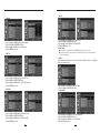
1
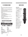
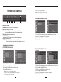
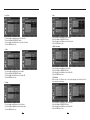
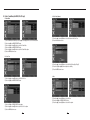
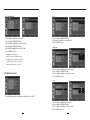
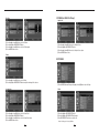
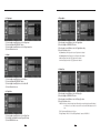
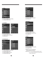
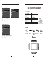
42inch Security LCD Monitor STM-42L Instruction Manual
Thank you for choosing this Samsung 42inch Security LCD Monitor product.
Before attempting to connect or operate this product, please read the instructions contained in
this manual carefully.
Please save this instruction manual for future reference.
1
ENGLISH
INSTRUCTION MANUAL
INSTRUCTION MANUAL
CONTENTS
IMPORTANT SAFETY INSTRUCTIONS.................................................. 3
SAFETY INSTRUCTION........................................................................... 4
CAUTIONS............................................................................................... 5
ATTENTION............................................................................................. 5
FCC RF INTERFERENCE STATEMENT................................................. 6
CONNECTING WITH EXTERNAL EQUIPMENT.................................... 6
REMOTE FUNCTIONS ........................................................................... 7
CONTROLS AND FUNCTIONS.............................................................. 8
IMPORTANT SAFETY INSTRUCTIONS
1) Read these instructions.
2) Keep these Instructions.
3) Heed all warnings.
4) Follow all instructions.
5) Do not use this apparatus near water.
6) Clean only with dry cloth.
7) Do not block any ventilation openings. Install in accordance with the manufacturer’s instructions.
8) D
o not install near any heat sources such as radiators, heat registers,stoves, or other apparatus (including amplifiers)
that produce heat.
9) Do not defeat the safety purpose of the polarized or grounding-type plug.
Apolarized plug has two blades with one wider than the other.
Agrounding type plug has two blades and a third grounding prong.
The wide blade or the third prong are provided for your safety.
If the provided plug does not fit into your outlet, consult an electrician for replacement of the bsolete outlet.
10) P rotect the power cord from being walked on or pinched particularly at plugs, convenience receptacles and the
point where they exit from the apparatus.
11) Only use attachment/accessories specified by the manufacturer.
12) U se only with the cart, stand, tripod, bracket or table specified by the manufacturer or sold with the apparatus.
When a cart is used, use caution when moving the cart/apparatus combination to avoid injury from tip-over.
D-SUB CONNECTOR PIN ASSIGNMENTS.........................................25
Dimension..............................................................................................25
POWER MANAGEMENT ....................................................................26
SPECIFICATIONS ................................................................................. 27
TROUBLESHOOTING GUIDE...............................................................28
CORRECT DISPOSAL OF BATTERIES IN THIS PRODUCT.................28
13) Unplug this apparatus during lightning storms or when unused for long periods of time.
14) R efer all servicing to qualified service personnel. Servicing is required when the apparatus has been damaged in
any way, such as power-supply cord or plug is damaged, liquid has been spilled or objects have fallen into the
apparatus the apparatus has been exposed to rain or moisture does not operate normally or has been dropped.
MEMO...................................................................................................29
2
3
INSTRUCTION MANUAL
INSTRUCTION MANUAL
SAFETY INSTRUCTION
CAUTIONS
- The apparatus shall not be exposed to dripping or splashing and that no objects filled with liquids, such as vases,
shall be placed no the apparatus.
The power supply cord is used as the main disconnect device, ensure that the socket-outlet is located/installed
near the equipment and is easily accessible.
- Minimum distances(e.g. 10cm) around the apparatus for sufficient ventilation.
“WARNING - To reduce the risk of fire or electric shock, do not expose the apparatus to rain or moisture.”
“The apparatus shall not be exposed to dripping or splashing and no objects filled with liquids, such as vases, shall
be placed on the apparatus.”
ATTENTION
Le cordon d`alimentation est utillsé comme interrupteur général. La prise de courant doit être située ou installée à
proximité du matériel et être facile d`accès
CAUTION
RISK OF ELECTRIC SHOCKS
DO NOT OPEN
CAUTION: TO REDUCE THE RISK OF ELECTRIC
SHOCK, DO NOT REMOVE COVER (OR BACK).
NO USER SERVICEABLE PARTS INSIDE. REFER
SERVICING TO QUALIFIED SERVICE PERSONNEL.
This symbol is intended to alert the user to the presence of uninsulated
“dangerous voltage” within the product’s enclosure that may be of suffcient
magnitude to constitute a risk of electric shock to persons.
This symbol is intended to alert the user to the presence of important
operating and maintenance(servicing) instructions in the literature
accompanying the appliance.
4
CAUTION TO SERVICE PERSONNEL
POWER SUPPLY CORD IS USED AS MAIN POWER DISCONNECT DEVICE IN THIS PRODUCT.
UNPLUG THIS PRODUCT FROM THE WALL OUTLET BEFORE REMOVING THE BACK COVER
AND SERVICING
EMISSION CHARACTERISTICS TESTED BY SEMKO
THIS PRODUCT HAS BEEN TESTED AND HAS SHOWN COMPLIANCE WITH THE NATIONAL
SPECIFICATIONS SUCH AS SWEDISH MPR 1990. 10. (MPR Ⅱ)
• NEVER REMOVE THE BACK COVER
Removal of the back cover should be carried out only by qualified personnel.
• DO NOT USE IN HOSTILE ENVIRONMENTS
To prevent shock or fire hazard, do not expose the unit to rain or moisture.
This unit is designed to be used in the office or home. Do not subject the unit to vibrations, dust of corrosive
gases.
• KEEP IN A WELL VENTILATED PLACE
Ventilation holes are provided on the cabinet to prevent the temperature from rising.
Do not cover the unit or place anything on the top of unit.
• AVOID HEAT
Avoid placing the unit in direct sunshine or near a heating appliance.
• TO ELIMINATE EYE FATIGUE
Do not use the unit against a bright back ground and where sunlight or other light sources will shine directly on
the monitor.
• BE CAREFUL OF HEAVY OBJECT
Neither the monitor itself nor any other heavy object should rest on the power cord.
Damage to a power cord can cause fire or electrical shock.
5
INSTRUCTION MANUAL
INSTRUCTION MANUAL
FCC RF INTERFERENCE STATEMENT
REMOTE FUNCTIONS
NOTE
This equipment has been tested and found to comply with the limits for a Class A digital device, pursuant to Part 15
of the FCC Rules. These limits are designed to provide reasonable protection against harmful interference in a
residential installation.
This equipment generates, uses and can radiate radio frequency energy and, if not installed and used in
accordance with the instructions, may cause harmful interference to radio communications. However, there is no
guarantee that interference will not occur in a particular installation.
If this equipment does cause harmful interference to radio or television reception which can be determined by
turning the equipment off and on, the user is encouraged to try to correct the interference by one or more of the
following measures.
- Reorient or relocate the receiving antenna.
- Increase the separation between the equipment and receiver.
- Connect the equipment into an outlet on a circuit different from that to which the receiver is connected.
- Consult the dealer or an experienced radio, TV technician for help.
- Only shielded interface cable should be used.
Finally, any changes or modifications to the equipment by the user not expressly approved by the grantee or
manufacturer could void the users authority to operate such equipment.
▶ DOC COMPLIANCE NOTICE
This digital apparatus does not exceed the Class A limits for radio noise emissions from digital apparatus set out
in the radio interference regulation of Canadian Department of communications.
B. REMOTE CONTROLLER
1. POWER(
) : Turn the power ON or OFF. There will be a few
seconds delay before the display appears.
5. MUTE : Mute the sound.
6. MENU : Activates and exits the On Screen Display.
8. VOL(◀ ▶) : Increases or decreases the level of audio volume.
4 5
10. SOURCE/SELECT : A
ccept your selection or displays the
current mode.
11
11. INFO : Input mode information Display.
13
12. STILL : Stop the picture.
17
21
14. P.INPUT : Select PC or video source.
15. P.POS : Move the position of sub picture for PIP mode.
17. SWAP : Alternates between main and sub picture.
6,7
8
9 10 11 12 13 14
15
16
17
1. HDMI IN
2. DVI IN
3. PC VGA IN
4. PC STEREO IN
5. AUDIO OUT
6. COMPONENT IN
7. COMPONENT AUDIO L/R IN
8. Trigger Input
9. AV 1 IN : Composite signal input for AV 1
10. AV 1 OUT : Video looping out for AV 1
11. AV 2 IN : Composite signal input for AV 2
12. AV 2 OUT : Video looping out for AV 2
13. S-VIDEO IN : Y/C separated signal input
14. S-VIDEO OUT : Y/C separated signal looping out
15. AV 2 AUDIO L/R IN : Audio L/R input. This input is for AV 2
16. AV 1, SVIDEO AUDIO L/R IN : Audio L/R input. This input is for AV 1, S-VIDEO
17. AC POWER IN
6
9
10
20. ACC (Auto Color Control) : Select Colour mode.
3
8
9. UP/DOWN : Move to OSD menu.
19. APC (Auto Picture Control) : Select picture mode.
2
5
7
7. EXIT : Exit the On Screen Display.
18. ARC (Aspect Ratio Control) : Select screen ratio.
1
3
4
6
4. HOLD : Stop the Trigger & Auto switching functions.
16. P.SIZE : C
hange the size of sub and main picture for PIP mode.
A. BACK PANEL CONTROL
2
3. AUTO : Auto geometry adjustment in PC Source.
13. PIP (Picture In Picture) : Activate PIP mode.
CONNECTING WITH EXTERNAL EQUIPMENT
1
2. SOURCE : Select pc or video(AV1/AV2/S-Video/Component/
HDMI/DVI/PC) sources.
21. S.SET : Select Sound mode main input or sub input
22. PC : Select PC mode(PC, DVI & HDMI).
23. AV : Select AV mode.(AV1, AV2 & S-VIDEO).
24. COMP : Select COMPONENT mode.
7
12
15
14
19
18
23
22
16
20
24
INSTRUCTION MANUAL
INSTRUCTION MANUAL
CONTROLS AND FUNCTIONS
· Tint : Increase or decrease the tint of the picture.
· Sharpness : Increase or decrease the sharpness of the picture.
A. CUSTOM MENU (For HDMI, DVI & PC Input)
1
2
3
4
5
6
7
8
9
C. FRONT KEY CONTROL
1. SOURCE/SELECT : Select PC or video. Select On Screen Display menu.
2. MENU : A
ctivate and exit the On Screen Display.
3/4. ▼ / ▲ : These buttons allow user to enter the sub-menu of the activated function.
The up (▲) button is HOLD function and stop the Trigger & Auto switching functions.
5/6. VOL ◀ /VOL ▶ : Adjust the volume and menu settings.
1) Press the MENU button and then press the up(▲) or down(▼) button to select the Custom.
7. POWER ON/OFF( / I )
Turns the power ON or OFF. There will be a few seconds delay before the display appears.
8. IR Sensor : Remote controller sensor.
9. POWER LED : T he power LED lights with green when the power is turned ON.
The power is turned off by pressing the power switch again and the power LED goes Red.
2) Press the up(▲) or down(▼) button to select the sub menu.
3) Press the left(◀) or right(▶) button to adjust the picture setting.
4) Press the MENU button to save.
• OSD MENU DESCRIPTION
A. CUSTOM MENU (Only Video Input)
B. Picture / Sound Menu (Only Video Input)
1. Picture Mode
1) Press the MENU button and then press the up(▲) or down(▼) button to select the Custom
2) Press the up(▲) or down(▼) button to select the sub menu.
3) Press the left(◀) or right(▶) button to adjust the picture setting.
4) Press the MENU button to save.
1) Press the MENU button and then press the up(▲) or down(▼) button to select the Picture / Sound.
2) Press the right(▶) or SOURCE/SELECT button.
3) Press the up(▲) or down(▼) button to select the Picture Mode.
· Brightness : Increase or decrease the intensity of the image.
4) Press the right(▶) or SOURCE/SELECT button.
· Contrast : Increase or decrease the intensity (lightness or dimness) of the image.
5) Press the up(▲) or down(▼) button to select the Picture Mode option.
· Color : Increase or decrease the colour of the picture.
6) Press the MENU button to save
8
9
INSTRUCTION MANUAL
INSTRUCTION MANUAL
2. Color Tone
5. Size
1) Press the up(▲) or down(▼) button to select the Color Tone.
2) Press the right(▶) or SOURCE/SELECT button.
3) Press the up(▲) or down(▼) button to select the Color Tone option.
4) Press the MENU button to save.
1) Press the up(▲) or down(▼) button to select the Size
2) Press the right(▶) or SOURCE/SELECT button.
3) Press the up(▲) or down(▼) button to select the Size option.
4) Press the MENU button to save.
6. NR (Noise Reduction)
3. Mute
1) Press the up(▲) or down(▼) button to select the Mute.
2) Press the right(▶) or SOURCE/SELECT button.
3) Press the up(▲) or down(▼) button to select the On or Off.
4) Press the MENU button to save.
4. Volume
1) Press the up(▲) or down(▼) button to select the Volume
2) Press the left(◀) or right(▶) button to adjust Volume setting.
3) Press the MENU button to save.
10
1) Press the up(▲) or down(▼) button to select the NR.
2) Press the right(▶) or SOURCE/SELECT button.
3) Press the up(▲) or down(▼) button to select the On or Off.
4) Press the MENU button to save.
7. 3D Comb filter
When used with a 3D comb filter, reduces color bleeding and graphic noise drastically for softer,
clearer, and higher-contrast images.
1) Press the up(▲) or down(▼) button to select the 3D Comb.
2) Press the right(▶) or SOURCE/SELECT button.
3) Press the up(▲) or down(▼) button to select the On or Off.
4) Press the MENU button to save.
11
INSTRUCTION MANUAL
INSTRUCTION MANUAL
B. Picture / Sound Menu (For HDMI, DVI & PC Input)
2-2. Color Tone (Custom)
1. Picture Mode
1) Press the MENU button and then press the up(▲) or down(▼) button to select the Picture/Sound.
2) Press the right(▶) or SOURCE/SELECT button.
3) Press the up(▲) or down(▼) button to select the Picture Mode.
4) Press the right(▶) or SOURCE/SELECT button.
5) Press the up(▲) or down(▼) button to select the Picture Mode option.
6) Press the MENU button to save.
1) Press the up(▲) or down(▼) button to select the Custom in the Color Tone.
2) Press the Menu button to save.
2-1. Color Tone
3) Press the up(▲) or down(▼) button to select the Red(R), Green(G) or Blue(B).
4) Press the left(◀) or right(▶) button to adjust color density.
5) Press the MENU button to save.
3. Size
1) Press the up(▲) or down(▼) button to select the Color Tone.
2) Press the right(▶) or SOURCE/SELECT button.
1) Press the up(▲) or down(▼) button to select the Size.
2) Press the right(▶) or SOURCE/SELECT button.
3) Press the up(▲) or down(▼) button to select the Size option.
3) Press the left(▶) or SOURCE/SELECT button again.
4) Press the up(▲) or down(▼) button to select the Color Tone option.
5) Press the MENU button to save.
12
13
INSTRUCTION MANUAL
INSTRUCTION MANUAL
4. PC control (Only PC Input)
1. PIP
1) Press the up(▲) or down(▼) button to select the PC.
1) Press the right(▶) or SOURCE/SELECT button.
2) Press up(▲) or down(▼) button to select the On or Off.
3) Press the MENU button to save.
2) Press the right(▶) or SOURCE/SELECT button.
3) Press the up(▲) or down(▼) button to select the PC sub menu.
4) Press the right(▶) or SOURCE/SELECT button.
5) Press the left(◀) or right(▶) button to adjust the PC setting.
2. Input Source
6) Press the MENU button to save.
· Auto Adjust : Auto geometry adjustment.
· Phase : Adjust the number of horizontal picture elements.
· H-Position : Move image horizontally on screen right or left.
· V-Position : Move image vertically on screen up or down.
· Frequency : Adjust the vertical noise of screen image.
1) Press the up(▲) or down(▼) button to select the Input Source.
2) Press the right(▶) or SOURCE/SELECT button.
3) Press the up(▲) or down(▼) button to select the Source option.
4) Press the MENU button to save.
C. PIP MENU (Only Video Input)
3. Size
1) Press the MENU button and then press the up(▲) or down(▼) button to select the PIP.
1) Press the up(▲) or down(▼) button to select the Size.
2) Press the right(▶) or SOURCE/SELECT button.
3) Press the up(▲) or down(▼) button to select the Size option.
4) Press the MENU button to save.
14
15
INSTRUCTION MANUAL
INSTRUCTION MANUAL
C. PIP MENU (For HDMI, DVI & PC Input)
4. Position
1. Input Source
1) Press the up(▲) or down(▼) button to select the Position.
2) Press the right(▶) or SOURCE/SELECT button.
3) Press the up(▲) or down(▼) button to select the Position option.
4) Press the MENU button to save.
1) Press the up(▲) or down(▼) button to select the Input Source.
2) Press the right(▶) or SOURCE/SELECT button.
3) Press the up(▲) or down(▼) button to select the Input Source option.
4) Press the MENU button to save.
5. Swap
D. SETUP MENU
1) Press the up(▲) or down(▼) button to select the Swap.
2) Press the right(▶) or SOURCE/SELECT button to swap the main image for the sub one.
1) Press the MENU button and then press the up(▲) or down(▼) button to select the Setup.
6. Sound Select
1. Reset
1) Press the up(▲) or down(▼) button to select the Sound Select.
2) Press the right(▶) or SOURCE/SELECT button.
3) Press the up(▲) or down(▼) button to select the Sound Select option.
4) Press the MENU button to save.
1) Press the right(▶) or SOURCE/SELECT button
2) Press the right(▶) or SOURCE/SELECT button again.
3) Press SOURCE/SELECT button to execute the reset.
· Reset : All settings go to the factory initialization.
16
17
INSTRUCTION MANUAL
INSTRUCTION MANUAL
5. Key Lock
2. Language
1) Press the up(▲) or down(▼) button to select the Language.
2) Press the right( ▶) or SOURCE/SELECT button.
3) Press the up(▲) or down(▼) button to select language.
4) Press the MENU button to save.
3. OSD Tone
1) Press the up(▲) or down(▼) button to select the Key Lock.
2) Press the right(▶) or SOURCE/SELECT button
3) Press the up(▲) or down(▼) button to select the On or Off.
4) Press the MENU button to save.
※ How to unlock
On the front key: Press the SOURCE/SELECT and MENU button at the same time over 3 seconds.
O
n the Remote Controller: The Remote Controller operates well because the Key Lock function is only allowed for
the front key of this product.
6. Trigger
Checks the alarm and signal change of external electronic devices (DVRs, Cameras, etc.) and displays
them on the monitoring screen.
1) Press the up(▲) or down(▼) button to select the OSD Tone.
2) Press the right(▶) or SOURCE/SELECT button
3) Press the up(▲) or down(▼) button to select the OSD Tone option.
4) Press the MENU button to save.
4. Blue Screen
1) Press the up(▲) or down(▼) button to select the Trigger.
2) Press the right(▶) or SOURCE/SELECT button.
6-1. Trigger Enable
1) Press the up(▲) or down(▼) button to select the Blue Screen.
2) Press the right(▶) or SOURCE/SELECT button.
3) Press the up(▲) or down(▼) button to select the On or Off.
4) Press the MENU button to save.
18
1) Press the up(▲) or down(▼) button to select the Trigger Enable.
2) Press the right(▶) or SOURCE/SELECT button.
3) Press the up(▲) or down(▼) button to select the On or Off.
4) Press the Menu button to save.
19
INSTRUCTION MANUAL
INSTRUCTION MANUAL
6-2. Trigger Input
6-5 Trigger Option
1) Press the up(▲) or down(▼) button to select the Trigger Input .
2) Press the right(▶) or SOURCE/SELECT button.
3) Press the up(▲) or down(▼) button to select the Trigger Input option.
4) Press the Menu button to save.
1) Press the up(▲) or down(▼) button to select the Trigger Option.
2) Press the right(▶) or SOURCE/SELECT button.
3) Press the up(▲) or down(▼) button to select the Trigger Option setting.
4) Press the Menu button to save.
6-3. Buzzer
· N/C (Normal Closed) : When Trigger cable is opened, Trigger function is activated.
· N/O (Normal Opened) : When Trigger cable is closed, Trigger function is activated.
· High : When Trigger signal is high(2~5[V]), Trigger function is activated.
· Low : When Trigger signal is low(0~0.6[V]), Trigger function is activated.
6-6. Display Type
1) Press the up(▲) or down(▼) button to select the Buzzer.
2) Press the right(▶) or SOURCE/SELECT button.
3) Press the up(▲) or down(▼) button to select the On or Off.
4) Press the Menu button to save.
6-4. Trigger Time
1) Press the up(▲) or down(▼) button to select the Display Type.
2) Press the right(▶) or SOURCE/SELECT button.
3) Press the up(▲) or down(▼) button to select the Display Type option.
4) Press the Menu button to save.
· PIP & FULL : If the type of image in the trigger input is different with we are watching, trigger image will be displayed
1) Press the up(▲) or down(▼) button to select the Trigger Time.
2) Press left(◀) or right(▶) button to adjust Trigger Time setting.
3) Press the MENU button to save.
20
as a small screen at a corner which you selected in PIP menu. Otherwise it will be displayed as a full
screen.
· FULL : Trigger image will be displayed as a full screen.
· The Type of Image 1 : AV1, AV2 or S-Video, The Type of Image 2 : Component, HDMI, DVI or PC.
21
INSTRUCTION MANUAL
INSTRUCTION MANUAL
7. Auto switching
1) Press the up(▲) or down(▼) button to select the Auto switching.
2) Press the right(▶) or SOURCE/SELECT button.
1) Press the up(▲) or down(▼) button to select the On or Off.
2) Press the Menu button to save.
7-3. Auto switching Time
7-1. Auto switching On/Off
1) Press the right(▶) or SOURCE/SELECT button.
2) Press the up(▲) or down(▼) button to select the On or Off .
3) Press the Menu button to save.
1) Press the up(▲) or down(▼) button to select the Time.
2) Press the left(◀) or right(▶) button to adjust the Time setting.
3) Press the MENU button to save.
8. Image Rotation
7-2. Auto switching Inputs enabled
1) Press the up(▲) / down(▼) button to select the Image Rotation.
2) Press the right(▶) or ENTER button.
1) Press the up(▲)or down(▼) button to select the Inputs enabled.
2) Press the right(▶) or SOURCE/SELECT button.
3) Press the up(▲) or down(▼) button to select the Input.
4) Press the right(▶) or SOURCE/SELECT button.
22
※ Image Rotation support Image Rotation prevents Image persistence.
The displayed image slightly moves when this function is On.
※ Image persistence : W
hen an LCD panel is continuously displaying the same image(graphic) for a long period of
time, a trace of the image can remain visibly. Image persistence is not a product defect, and all
LCD products are subject to image persistence.
23
INSTRUCTION MANUAL
INSTRUCTION MANUAL
D-SUB CONNECTOR PIN ASSIGNMENTS
8-1. Image Rotation On/Off
• PIN ASSIGNMENTS
1) Press the right(▶) or SOURCE/SELECT button.
2) Press the up(▲) or down(▼) button to select the On or Off .
3) Press the Menu button to save.
Pin 1
RED VIDEO
Pin 9
Pin 2
GREEN VIDEO
Pin10
SIGNAL CABLE DETECT
Pin 3
BLUE VIDEO
Pin 11
GROUND
Pin 4
GROUND
Pin 12
SDA(for DDC)
Pin 5
GROUND
Pin 13
H-SYNC.(or H+V SYNC.)
Pin 6
RED GROUND
Pin 14
V-SYNC.
Pin 7
GREEN GROUND
Pin 15
SCL(for DDC)
Pin 8
BLUE GROUND
D-SUB
8-2. Image Rotation Min(Time control)
• ACCESSORY
1. User’s Manual
1) Press the up(▲) or down(▼) button to select the Time.
2) Press the left(◀) or right(▶) button to adjust the Time setting.
3) Press the MENU button to save.
2. Power Cord
3. Remote Controller
& Batteries
4. VGA Cable
Dimension
1063
120
655
24
25
5. Trigger Cable
INSTRUCTION MANUAL
INSTRUCTION MANUAL
SPECIFICATIONS
POWER MANAGEMENT
STM-42L
This monitor features a power management system to “power down” upon receipt of the VESA DPMS(The display
power management signaling) from a VESA DPMS video card.
The VESA DPMS-compliant video card performs this signaling system through not sending horizontal, vertical, or
sync signal.
This monitor enters an appropriate mode through identifying each of the three modes of the signaling system.
42˝ Diagonal AM-TFT(Active-Matrix)
Pixel pitch(mm) : 0.227mm(H) x 0.681mm(V)
BRIGHTNESS : 500cd/㎡(Typical)
LCD- Type
CONTRAST RATIO : 1100 :1(Typical)
• POWER CONSUMPTION : 230W(WXGA) / 250W(WUXGA)
RESPONSE TIME : 5msec(G-to-G)
• LED INDICATOR
The power management feature of the monitor is comprised of four stages: On(Green), Standby, Suspend, Active
off(Red on/off 1 sec) and Unsupported mode(Green).
MODE
ON
STANDBY
SUSPEND
ACTIV OFF
UNSUPPORTES
MODE
POWER OFF
VIEWING ANGLE : 178°/178°(H/V)
1366X768 @60Hz
HORIZONTAL : 31- 64KHz
VERTICAL : 56-75Hz
FREQUENCY
LED COLOR
GREEN
Normal Operation
RED ON/OFF
1 SEC
Screen blanks after preset idle time And some electronic circuits or all
Circuitry in the monitor shut down.
S-VIDEO(1ch input (Y/C), loop-through out)
GREEN
Normal operation but the on screen Display will show error massage
DVI D(Digital Video Interface)
RED
MONITOR OPERATION
RESOLUTION (H x V)
VIDEO(2ch input 1.0Vp-p, 75Ω terminated, loop-through out)
COMPONENT(Y,Pb,Pr, Sound L/R)
INPUT SIGNAL
Not Operation
HDMI(High Definition Multimedia Interface)
PC RGB
AV(composite) Sound in/Out
PC Stereo Sound
Audio Out
ACTIVE DISPLAY
AREA (W x H)
930mm X 523mm (36.61’’ X 20.59’’)
PACKING DIMENSIONS
(W x H x D)
1300mm X 885mm X 390mm
(51.18’’ X 34.84” X 15.35”)
Net Weight : 31kg (68.34 lbs)
WEIGHT
Gross Weight : 35kg (77.16 lbs)
ELECTRICAL RATINGS
AC100-240V,50/60Hz (Auto Switching)
• NOTE : Technical specifications are subject to change without notice.
26
27
MEMO
INSTRUCTION MANUAL
TROUBLESHOOTING GUIDE
TROUBLE
TROUBLESHOOTING TIP
No image on display screen
1. Check that power cord of the monitor have been connected securely
into wall outlet or grounded extension cable or strip.
2. Power switch should be in the ON position and LED is lit.
3. Check that the Brightness and / or the Contrast adjustments of the Display
haver not been turned down to minimum levels.
“Check Input Signal” message
on screen
1. The signal cable should be completely connected to the video card /
computer
2. The video card should be completely seated in its slot and the computer is
switched ON.
Display image is not centered, too
small or toolarge in PC mode
Push the down key in front side or Auto key in remocon.
Vertical or Horizontal noise is
present in the picture
Adjust Clock and Phase in the OSD.
CORRECT DISPOSAL OF BATTERIES IN THIS PRODUCT
28
MEMO
MEMO
SALES NETWORK
•
AMSUNG TECHWIN CO., LTD.
S
145-3, Sangdaewon1-dong, Jungwon-gu, Seongnam-si, Gyeonggi-do, 462-703, Korea
TEL : +82-31-740-8151~8 FAX : +82-31-740-8145
•
AMSUNG TECHWIN AMERICA Inc.
S
1480 Charles Willard St, Carson, CA 90746, UNITED STATES
Tol Free : +1-877-213-1222 FAX : +1-310-632-2195
www.samsungcctvusa.com
www.samsungtechwin.com
www.samsungcctv.com
•
AMSUNG TECHWIN EUROPE CO., LTD.
S
Samsung House, 1000 Hillswood Drive, Hillswood Business
Park Chertsey, Surrey, UNITED KINGDOM KT16 OPS
TEL : +44-1932-45-5300 FAX : +44-1932-45-5325
P/No. : L39ME0187 Rev.0
VAN 09. 05