1
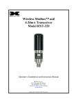
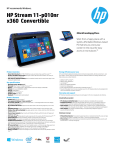
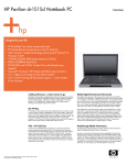
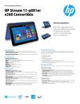
RXT Wireless
Configuration Tool
Operator’s Instruction Manual
DETCON, Inc.
3200 Research Forest Dr.,
The Woodlands, Texas 77387
Ph.281.367.4100 / Fax 281.298.2868
www.detcon.com
September 2, 2011 • Document # 3751 • Revision 0.0
RXT Wireless Configuration Tool
Page intentionally blank
Shipping Address: 3200 A-1 Research Forest Dr., The Woodlands Texas 77381
Mailing Address: P.O. Box 8067, The Woodlands Texas 77387-8067
Phone: 888.367.4286, 281.367.4100 • Fax: 281.292.2860 • www.detcon.com • [email protected]
RXT WCT Instruction Manual
ii
RXT Wireless Configuration Tool
Table of Contents
1.0
1.1
2.0
2.1
2.2
3.0
Introduction.............................................................................................................................................. 1
Description ........................................................................................................................................... 1
Power and I/O Connections .................................................................................................................... 1
Powering the RXT WCT ...................................................................................................................... 1
USB SNAP Stick.................................................................................................................................. 2
Operation and Configuration ................................................................................................................. 2
3.1
Operator Interface................................................................................................................................. 3
3.2
Main Configuration Tool Screen.......................................................................................................... 4
3.3
Create Configuration File (RXT-300 Only) ......................................................................................... 5
3.3.1
Network/Zone(s) Tab .................................................................................................................... 5
3.3.2
RXT(s) Tab ................................................................................................................................... 6
3.3.3
Device(s) Tab ............................................................................................................................... 8
3.4
View/Edit Configuration File (RXT-300 Only) ................................................................................. 10
3.5
Wireless Network ............................................................................................................................... 10
3.5.1
My Network ................................................................................................................................ 11
3.5.2
Operations .................................................................................................................................. 12
3.5.3
RXTs In My Network .................................................................................................................. 13
3.5.4
Search Other Networks .............................................................................................................. 14
3.5.5
RF Analyzer................................................................................................................................ 16
3.5.6
Monitor Network ........................................................................................................................ 17
3.5.7
Network Activity ......................................................................................................................... 17
3.6
File Manager....................................................................................................................................... 17
3.7
Time and Date .................................................................................................................................... 18
4.0
Example RXT-320 Configuration ........................................................................................................ 19
5.0
Example RXT-300 Configuration ........................................................................................................ 22
6.0
Warranty ................................................................................................................................................ 31
7.0
Specifications.......................................................................................................................................... 32
7.1
7.2
Spare Parts.......................................................................................................................................... 32
Revision Log ...................................................................................................................................... 33
Table of Figures
Figure 1 RXT Wireless Configuration Tool...................................................................................................... 1
Figure 2 USB SNAP Stick ................................................................................................................................ 2
Figure 3 Configuration Tool Selection Screen .................................................................................................. 2
Figure 4 MAC Address and Serial Number ...................................................................................................... 3
Figure 5 Alphanumeric Keypad and QWERTY Keyboard............................................................................... 3
Figure 6 RXT-300 Main Configuration Tool Screen ........................................................................................ 4
Figure 7 RXT-320 Main Configuration Tool Screen ........................................................................................ 4
Figure 8 Network/Zone(s) Tab.......................................................................................................................... 5
Figure 9 RXT(s) Tab ......................................................................................................................................... 7
RXT WCT Instruction Manual
iii
RXT Wireless Configuration Tool
Figure 10 Device(s) Tab.................................................................................................................................... 8
Figure 11 View/Edit Configuration File Screen................................................................................................ 10
Figure 12 RXT-300 Wireless Network Screen ................................................................................................. 11
Figure 13 My Network Section ......................................................................................................................... 11
Figure 14 RXT-320 Operations Section............................................................................................................ 12
Figure 15 RXT-300 Operations Section............................................................................................................ 12
Figure 16 RXTs In My Network Section .......................................................................................................... 13
Figure 17 RXT Function Buttons ...................................................................................................................... 13
Figure 18 Search Other Networks Operational Button ..................................................................................... 14
Figure 19 Search Channels Section................................................................................................................... 14
Figure 20 Operations Section ............................................................................................................................ 15
Figure 21 RXTs Found Section......................................................................................................................... 15
Figure 22 RF Analyzer ...................................................................................................................................... 16
Figure 23 Monitor Network Window................................................................................................................ 17
Figure 24 Network Activity Section.................................................................................................................. 17
Figure 25 File Manager Screen ......................................................................................................................... 18
Figure 26 System Date and Time Screen .......................................................................................................... 19
Figure 27 RXT-320 Wireless Network Screen ................................................................................................. 20
Figure 28 RXT-320 Wireless Network Screen ................................................................................................. 20
Figure 29 RXT-320 Search Other Networks Screen ......................................................................................... 21
Figure 30 RXT-300 Create Configuration File Screen ..................................................................................... 23
Figure 31 RXT 1 700 Sensor............................................................................................................................. 24
Figure 32 RXT 2 100 Sensor............................................................................................................................. 24
Figure 33 RXT 3 Alarm Station ........................................................................................................................ 25
Figure 34 RXT 4 Analog Sensor ....................................................................................................................... 26
Figure 35 RXT 5 HMI....................................................................................................................................... 26
Figure 36 Device 1 700 Sensor ......................................................................................................................... 27
Figure 37 Device 2 100 Sensor ......................................................................................................................... 28
Figure 38 Device 3 Analog Sensor.................................................................................................................... 29
Figure 39 RXT-300 Wireless Network Screen ................................................................................................. 30
Figure 40 RXT-300 Search Other Networks Screen ......................................................................................... 30
List of Tables
Table 1 RXT-320 Sample Exercise................................................................................................................... 19
Table 2 RXT-300 Sample Exercise................................................................................................................... 22
RXT WCT Instruction Manual
iv
RXT Wireless Configuration Tool
1.0 Introduction
1.1 Description
The RXT Wireless Configuration Tool is a custom device designed to configure Detcon’s RXT-300 and RXT320 SmartWireless™ transceivers. These RXT series transceivers enable wireless communication between the
controllers, sensors and alarm stations of any gas detection system. The RXT Wireless Configuration Tool
(WCT) is used to configure and change the wireless channel on a collection of RXT transceivers in such gas
detection systems and to configure RXT-300 wireless networks.
The RXT WCT is a lightweight and powerfully equipped device with a 10.1” touch panel widescreen LCD for
display and user input. It interfaces with a USB wireless radio of the same type that is installed in the RXT
transceivers so it can communicate with and configure them. It can be powered by 100-240VAC with the
supplied AC adapter or operate off of the internal rechargeable battery for up to 8 hours on a single charge.
Figure 1 RXT Wireless Configuration Tool
The radios in the RXT WCT and the RXT transceivers are Radio Frequency Engines (RFE) based upon the
IEEE 802.15.4 standard. For these radios to communicate with each other they must be set to the same RF
Channel and Network ID. The radios can be set to one of 16 RF channels, 0–15 and many thousand Network
IDs. Normally the RF channel and Network ID are set to the same physical value to avoid confusion.
Consequently up to 16 RXT series based systems can be located in the same general area.
2.0 Power and I/O Connections
2.1 Powering the RXT WCT
The RXT WCT can be powered by 100-240VAC with the supplied AC adapter or operate off of the internal
rechargeable battery for up to 8 hours on a single charge for maximum portability. The battery’s charging
technology provides a 4:1 work-to-charge ratio that ensures rapid charging for reduced downtime. It requires
only a two hour charge time for a full charge. A visible battery charge gauge is also located on the front of the
device to indicate the remaining charge level with the push of the button located next to the gauge.
To start using the RXT WCT, power must first be applied using the power button located on its left side. This
will initialize the configuration tool and bring up the main menu. To power off, select the SHUTDOWN button
which brings up a final confirmation menu where SHUTDOWN or REBOOT can be selected. Select
SHUTDOWN again to complete the power off procedure.
RXT WCT Instruction Manual
Rev. 0.0
Page 1 of 33
RXT Wireless Configuration Tool
2.2 USB SNAP Stick
The SNAP Stick is a compact USB device used to enable the RXT WCT to communicate with RXT series
transceivers. This device is about the size of a thumb drive and is designed to act as a bridge between an RXT
wireless network and the WCT via its built-in wireless radio. The SNAP Stick connects to the WCT’s USB
port located on its left side.
Figure 2 USB SNAP Stick
NOTE: The SNAP Stick is only needed for the WCT’s Wireless Network section. For all
other sections, the SNAP Stick is not required and may be removed if, for example, a USB
DRIVE needs to be installed for file management (See section 3.6).
3.0 Operation and Configuration
Upon power up, the RXT WCT offers two configuration tool selections: RXT-300 or RXT-320. After the
selection, the main configuration tool screen for the corresponding transceiver type will appear of which
Wireless Network will be the most commonly selected. In the Wireless Network screen the user can perform
multiple tasks such as finding RXTs across different networks and selecting RXTs to move to a new network.
In this way the user can change new or existing systems to a different network or re-arrange RXTs to form a
totally different system on a specific wireless network.
Figure 3 Configuration Tool Selection Screen
To set up a collection of RXTs to a particular network (RF Channel / Network ID) the user will generally
perform the following tasks:
RXT WCT Instruction Manual
Rev 0.0
Page 2 of 33
RXT Wireless Configuration Tool
•
•
•
•
•
Identify RXTs to be set up on a single network using their serial numbers.
Identify a new wireless network to place all RXTs.
If there are unwanted RXTs on the new wireless network, identify a different unused network.
Move unwanted RXTs to the different network.
Move selected RXTs to new network.
Upon completion, only the selected RXTs will be in the new wireless network. If RXTs have issues
communicating on the new network due to interference, the procedure can be performed again and RXTs can
be placed on a different network (RF Channel/Network ID).
To identify the RXTs as mentioned above, each Detcon RXT transceiver has been engraved with a unique
serial number located on the RXT’s metal back plate. This serial number consists of 6 characters in the form
of XX.XX.XX where the X can be characters 0-9, A-F. If the back plate is not available, the serial number
will be the same as the transceiver’s network address which is the last 6 characters of the MAC address found
on the RXT’s RF engine PCA and can be accessed by removing its black cap.
MAC Address
In this example, the serial
number is 03.C8.B7
Figure 4 MAC Address and Serial Number
When the WCT searches for wireless radios on a given RF Channel, this unique number will appear on the
screen as each one is found. In this way, the user can identify precisely which RXTs are on a network.
3.1 Operator Interface
The operator interface of the RXT WCT is accomplished via its 10.1” touch panel LCD. Selections can be
made simply by touching the menu buttons on the screen. To enter or change values, touch the corresponding
fields to make them active at which time a virtual alphanumeric keypad or virtual QWERTY keyboard will
appear depending on the field selected. Enter the desired data or values and select the Enter button to save the
entry. Selecting the Cancel button at any time during the data entry modes will return the user to the previous
screen without any changes having been made.
Figure 5 Alphanumeric Keypad and QWERTY Keyboard
RXT WCT Instruction Manual
Rev 0.0
Page 3 of 33
RXT Wireless Configuration Tool
3.2 Main Configuration Tool Screen
The main configuration tool screen offers six menu selections for the RXT-300 configuration tool and four
menu selections for the RXT-320 configuration tool as well as a Shutdown button for both. These menu
selections will in turn bring up separate screens when selected.
Create Configuration File
(Available for RXT-300 only)
View/Edit Configuration File
(Available for RXT-300 only)
Wireless Network
File Manager
Switch Configuration Tool
Time and Date
Builds and saves a system configuration file that is used to load to RXT-300s.
Search, browse and move RXTs in different wireless networks.
Used to move, copy or delete files.
Allows user to choose between RXT-300 or RXT-320 system.
Sets the time & date.
Shutdown
Will shutdown or reboot the RXT WCT.
Allows system configuration file to be changed and saved.
Figure 6 RXT-300 Main Configuration Tool Screen
Figure 7 RXT-320 Main Configuration Tool Screen
RXT WCT Instruction Manual
Rev 0.0
Page 4 of 33
RXT Wireless Configuration Tool
3.3 Create Configuration File (RXT-300 Only)
The Create Configuration File screen is available only for the RXT-300 configuration tool and can be selected
from its main configuration tool screen. It is used for building a system configuration accordingly. This
configuration can then be saved and loaded wirelessly to all RXT-300s specified in the configuration file.
The configuration settings include much of the same information needed when setting up a control system for
a gas detection system. This would include both sensor settings and alarm settings. The sensor settings include
parameters such as Modbus™ addresses, registers to be read that include the concentration, settings for alarm
thresholds and whether these are ascending or descending. System settings would be for alarms, how they are
associated with sensors and their properties such as Energized/De-Energized, Latching/Non Latching and
Silence-able/ Non Silence-able.
These configuration settings are needed at different stages of building a configuration using the RXT WCT.
Many parameters will default to values that can be used without change. Others will have to be determined by
the user and the specific application such as sensor types and alarm thresholds and, for each RXT-300, what
devices are attached and how are they configured. Most of this data will be entered in a top-down approach,
starting with system parameters, then RXT-300 parameters and finally the sensor parameters. The
configuration file screen consists of three main tabs required to build a system using this top-down approach:
Network/Zone(s)
RXT(s)
Device(s)
3.3.1
Network/Zone(s) Tab
The Network/Zone(s) tab is used to set up the RF Channel and Network ID for all radios in the system.
Network Sleep and Zones are also set up here.
Figure 8 Network/Zone(s) Tab
RXT WCT Instruction Manual
Rev 0.0
Page 5 of 33
RXT Wireless Configuration Tool
System Name
Network ID
RF Channel
Alphanumeric name for the Wireless Network – This field can be set to any desired value.
Sets all RXT-300 radios in system to Network ID. (Values: 0-65534) Networks with
different network IDs can occupy the same RF channel.
Sets all RXT-300 radios in system to an RF channel. (Values: 0-15)
NOTE: RXT-300s will only communicate with other RXT-300s with the same network ID
and RF channel.
NOTE: It is recommended to use the same Network ID as RF Channel which would allow for
up to 16 systems (RF Channel/Network ID = 0-15). If two or more systems are configured on
the same RF Channel but have different Network IDs that are nearby, they will have to share
that channel, consequently, it will take longer to poll and will cause data re-transmits to occur.
Network Sleep
Sets the time in seconds that the network will sleep after polling all devices in the system
(Values: 0-1000). Used to extend battery life but also lengthens time between sensor
updates. Set to 0 to disable Network Sleep. Default setting is 10 seconds.
Zones section allows the user to create up to 16 independent alarm zones. As each Zone is added, the RXT
WCT will create a default name. The user can change these to a more a meaningful name if needed. These
Zone names will be selectable during the configuration of the RXT-300s in the system.
Zone Name
The user will enter Alarm Zone names here. Up to 16 Zones can be added.
This is a system wide setting like network sleep since it affects all RXT-300s in the system. The user can
leave one Zone defined if all Alarm Stations will respond to the same Alarm conditions. Otherwise, the user
will need to determine the number of Zones in the system and which RXT-300s will be included in those
zones. A single RXT-300 can be in multiple zones.
NOTE: A network configuration file must contain at least one Alarm Zone.
3.3.2
RXT(s) Tab
The RXT(s) tab is used to set up the RXT-300 transceivers that have been identified to be added to the system.
Since this is the heart of each of the Station types, there are several parameters that must be set. These include
Modbus™ settings and Alarm settings. The Alarm settings include RXT-300 Alarm event mapping to Alarm
Outputs, the Zone(s) that the RXT-300 will be placed in and the Alarm Output property settings. Some of
these are grouped and set within submenus on the RXT WCT.
RXT WCT Instruction Manual
Rev 0.0
Page 6 of 33
RXT Wireless Configuration Tool
Figure 9 RXT(s) Tab
RXT Name
Alphanumeric name for the corresponding RXT-300 in the system which can be set to a
meaningful name by the user. A maximum of 32 characters is allowed of which only the
first 15 characters will appear on an HMI Panel display.
Unique Device ID Uniquely identifies the RXT-300 using the serial number that is stamped on the metal
back plate of the RXT-300 itself. (Last 6 digits of the radio’s MAC address)
Modbus Address
This is the Modbus™ address of the RXT-300 and auto-increments to the next address
starting at 161 each time an RXT-300 is added. It is used for such things as addressing
4-20mA sensors local to that RXT-300. This field is read only and not user configurable.
Priority
Used in guiding the election of the Master RXT-300 and can have a value of 0-255.
Priority is incremented starting at 1 each time an RXT-300 is added. The RXT-300 with a
priority of 1 will be the first to be elected as a Master if it is powered on and working and
an RXT-300 with priority of 255 would be the last one elected as Master. If two or more
RXT-300s have equal priority, the one with the lowest serial number will be selected. If a
priority of 0 is assigned to an RXT-300 it will never try to become Master of the network.
Alarm Station
Choose Alarm Station if the RXT-300 will function as an alarm station.
Battery Attached
Choose Battery Attached if a battery is attached.
Low Battery Alarm This value is the low battery threshold that triggers an alarm. It represents the time
remaining before the battery is depleted and is set in number of Days/Hours/Minutes. If
the RXT-300 functions as an alarm, this value is represented as a percentage of the charge
remaining before the battery is depleted. The alarm will trigger when the battery charge
falls below the set value. The user should set the threshold based upon the amount of time
it would take to replace the battery.
Associated Zones
This is a submenu that allows the user to select which Alarm Zones this RXT-300 will be
a part of. One or more Zones can be selected depending on how many Zones were
previously defined.
RXT WCT Instruction Manual
Rev 0.0
Page 7 of 33
RXT Wireless Configuration Tool
Alarm Out Events This is a submenu that allows the user to select which RXT-300 events will generate
alarms and which relays will be triggered from the events. There are four events that are
monitored: Network Down, RXT Offline, Battery Fault and Battery Alarm. All four RXT
events default to relay 4 but can be individually assigned to any relay.
Network Down occurs when no Master has been detected for an extended period.
RXT Offline occurs when communication is lost to one or more RXT-300s in the system.
Battery Fault occurs when a battery is attached or detected and then communication is lost
with the battery.
Battery Alarm occurs when the battery life remaining drops below the Low Battery
threshold set previously.
Alarm Out
Properties
Advanced
3.3.3
This is a submenu where the user sets the relay properties for the relay outputs of the
current RXT-300 and can be ignored if the Alarm outputs are unused. It sets the Energize/
Non-Energize, Latching/Non-Latching, Silence-able/Non-Silence-able properties for each
Alarm output.
This is a submenu of advanced settings that can be adjusted such as Modbus™ timeouts
and retries or network timeouts and retries. These would not be changed normally unless
directed to do so by Detcon personnel.
Device(s) Tab
The Device(s) tab is used to set up devices (sensors) that have been identified to be added to the system. These
settings define the Sensor type, Modbus™ settings and Alarm settings. All sensors are accessed using
Modbus™ protocol including the 4-20mA sensors. Alarm settings include thresholds and mapping of Alarm
events to relay outputs.
Figure 10 Device(s) Tab
RXT WCT Instruction Manual
Rev 0.0
Page 8 of 33
RXT Wireless Configuration Tool
Device Name
Alphanumeric name for the corresponding sensor in the system which can be set to a
meaningful name by the user. A maximum of 32 characters is allowed of which only the
first 15 characters will appear on an HMI Panel display.
Device Type
The user can select from a pre-defined list of Detcon devices which will automatically
populate some of the parameters for the user. The available device types are 100 Series,
600 Series, 600D Series, 700 Series and RXT-300.
RXT
The user selects from a list of RXT-300s using the RXT name that identifies the RXT-300
this device is attached to. The RXT-300 must be added first.
Modbus Address
Sets the system wide Modbus™ address of this device. The address will auto-increment
to the next Modbus™ address as each device is added and starts at address 1.
Device Modbus
Address
Sets the address of the device local to this RXT-300. This will be the same as the
Modbus™ address set above unless it is a 100 series sensor without the LED display
which will have a fixed address of 1. The system wide Modbus™ address is translated on
this RXT-300 to the Device address. For example, if the Modbus™ address is set to 4 and
the Device address is set to a 1, the RXT-300 will poll address 1 on its local Modbus™
interface but will present this to the network as Modbus™ address 4. So the HMI Panel
will actually request sensor data from Modbus™ address 4 in this instance.
Range
Defaults to 100 but defines the range of readings that will be read from a device. For 420mA devices, a reading of 400 to 2000 represents 4mA to 20mA. If a range of 100 is
entered internally, the RXT-300 will translate Alarm thresholds entered later into the
appropriate 4-20mA thresholds internally. So if an Alarm threshold is set to a value of 10,
this is 10% of the 4-20mA reading which equates to a reading of 560 internally.
Starting Register
Defines the starting address used to poll the Modbus™ device.
Registers to Read
Defines the number of Modbus™ registers to read. This is limited to 22 registers.
Reading Register
Defines the register that contains the concentration (reading) value used for Alarm
processing and for displaying on an HMI Panel. It is the physical register number with 0
being the first register on a Modbus™ device.
Alarm Setpoints
There are three setpoints: Alarms 1, 2 and 3 that represent the three Alarm thresholds for
the sensor reading. A value is entered and defined whether it is an ascending or
descending threshold. Every time the device is read the reading value is compared with
this threshold and will generate an Alarm event if the threshold is crossed.
Alarm Out Events This is a submenu that allows the user to select which device events will generate alarms
and which relays are triggered. There are six events that are monitored: Alarm 1,
Alarm 2, Alarm 3, Fault, Communication Error and Modbus Exception. These can be
mapped to any of the four relays.
Alarm 1, Alarm 2, Alarm 3 events occur when the user defined setpoints are crossed.
Fault is monitored if it is a Detcon device type and the device has a fault status that can be
read.
Communication Errors occur when there is no response from a Modbus™ read.
Modbus Exception occurs when the device returns Modbus™ exceptions during a read.
RXT WCT Instruction Manual
Rev 0.0
Page 9 of 33
RXT Wireless Configuration Tool
3.4 View/Edit Configuration File (RXT-300 Only)
The View/Edit Configuration File screen is available only for the RXT-300 configuration tool and can be
selected from its main configuration tool screen. It is used for viewing and editing a configuration file that has
been previously saved. To open a file, the user must first select the appropriate file from the available list and
then select “Open”. Only one file may be selected at a time. The user will then be able to view and make any
changes to the configuration just like the Create Configuration File screen (See section 3.3).
Figure 11 View/Edit Configuration File Screen
3.5 Wireless Network
The Wireless Network screen is selected from the main configuration tool screen and is used for finding and
loading configuration files to RXTs on the wireless network. There are three main sections on this screen: My
Network, Operations and RXTs in My Network. At the bottom of the screen there is a single status line of any
ongoing operations.
When entering this screen, the RXT WCT will connect to the USB SNAP Stick and locate itself on the channel
and network ID of the SNAP Stick. The current channel and network ID of the WCT is shown in the My
Network section of the screen. The WCT will show a red status line giving the progress as it goes through the
initialization. The following actions will take place:
•
•
•
•
Initialize connection to USB SNAP Stick.
Initialize the RXT WCT to Network ID and Channel shown in My Network.
Search for other RXT WCTs on that wireless network and assign an address to itself that does not
conflict.
Starts Search My Network for RXTs in My Network. Results are listed in RXTs in My Network.
RXT WCT Instruction Manual
Rev 0.0
Page 10 of 33
RXT Wireless Configuration Tool
NOTE: RXTs that are part of an operational system are in constant communication with the
master RXT. When searching for RXTs on an operational network, the WCT will temporarily
disable sleep for the current network it is searching. The network sleep function is restored
once the WCT has completed searching the network.
Figure 12 shows the Wireless Network screen for the RXT-300 configuration tool after initialization has been
completed. The red status line shows that the search is complete and the RXTs In My Network section shows
the list of RXTs found. The screen is divided into multiple sections and is discussed below. The red status
line at the bottom of the RXT WCT will always show the current operational status.
Figure 12 RXT-300 Wireless Network Screen
3.5.1
My Network
The My Network section shows the current Network ID and RF Channel for the RXT WCT. Consequently, the
WCT can only search and re-configure RXTs with the same channel and network ID and will perform
operations on this screen based on this wireless network. RXTs will only communicate with one another if
they are set to the SAME Channel and Network ID. Entering a new value in either of these fields will cause
the RXT WCT radio to reboot and update to the new setting.
Channel
Network ID
Sets RF Channel on WCT radio. (Range of values: 0 – 15)
Sets Network ID on WCT radio. (Range of values: 0 – 65534)
Figure 13 My Network Section
RXT WCT Instruction Manual
Rev 0.0
Page 11 of 33
RXT Wireless Configuration Tool
NOTE: It is recommended that the Network ID be set to the same value as the Channel to
simplify settings.
3.5.2
Operations
The Operations section encompasses three main operations performed for both the RXT-300 and RXT-320.
Search My Network Searches for RXTs in My Network. Results are listed in RXTs in My Network.
Reboot RXT(s)
Reboots the radios on RXTs that are selected in RXTs in My Network.
Upload Image
Changes the RXT’s image on RXTs selected in RXTs in My Network.
Figure 14 RXT-320 Operations Section
The Search My Network operation starts a search for RXTs based upon the Channel and Network ID currently
set in My Network. The RXT WCT will continue the search while RXTs continue to respond. The RXTs that
are found are listed in the RXTs In My Network section. As the search proceeds, a Cancel button is displayed
and if selected will immediately stop the search.
NOTE: RXTs found indicates there was a response at the time during the search. The search
WILL NOT remove any RXTs from the list, meaning that if an RXT is powered down after the
search was done, the list will NOT be updated. To generate a fresh list of RXTs, the RXTs In
My Network list must be cleared and then the search can be run again to find the current RXTs.
The Reboot RXT(s) operation can be used to resolve issues when RXTs are not operating properly.
The Upload Image operation should only be used when directed by Detcon personnel at the factory and is used
to change the image on the RXT radio.
Four additional operations can be performed for RXT-300s only. These operations are specific to the RXT300’s capabilities.
Config Mode
Configure RXT(s)
Restore NV Defaults
Clear RXT
Turns the RXT’s configuration mode ON or OFF.
Loads the RXT with the selected configuration file.
Restores the non-volatile memory with default parameters.
Erases the RXT’s current configuration. (Performed by Detcon personnel only)
Figure 15 RXT-300 Operations Section
RXT WCT Instruction Manual
Rev 0.0
Page 12 of 33
RXT Wireless Configuration Tool
The Config Mode operation allows the user to turn ON or OFF the selected RXT’s configuration mode. This
mode must be turned ON in order for the RXT to be configured.
The Configure RXT(s) operation will configure the selected RXTs by loading it with the selected configuration
file.
The Restore NV Defaults operation will restore non-volatile memory with default parameters.
The Clear RXT operation will erase the current configuration of the selected RXTs and should only be
performed by Detcon personnel.
3.5.3
RXTs In My Network
The RXTs In My Network section is populated with RXTs when the Search My Network operation is
performed. It will display the RXTs Network Address, Device Type, RFE Version, RFE Image Version and
Firmware Version as each RXT responds to the search request. These columns can be sorted ascending or
descending by selecting the actual heading at the top of the list. RXT Count gives the current number of RXTs
that were found which is updated as new ones respond.
Figure 16 RXTs In My Network Section
NOTE: Operations such as Search My Network can be cancelled by selecting the Cancel
button when it appears. The Cancel button will only appear if the operation can be cancelled.
For example, if the user knows all the RXTs have already been found and the process has not
completed, the user can cancel the search operation to save time.
Once Search My Network is completed, RXTs found are displayed and the user can now select specific RXTs
to perform operations on. The functions on the bottom of the RXTs in My Network section allow for viewing
and selecting RXTs to perform operations on.
Figure 17 RXT Function Buttons
RXT WCT Instruction Manual
Rev 0.0
Page 13 of 33
RXT Wireless Configuration Tool
Select All
Unselect All
Clear
Up/Down Arrows
Selects all RXTs in the RXTs in My Network section including those not displayed if
multiple pages are available.
Unselects all RXTs in the RXTs in My Network section including those not displayed if
multiple pages are available.
Removes any RXTs that are selected in the RXTs in My Network section.
These are page up and page down functions if multiple pages are available.
All RXTs can be cleared from the list by performing a Select All and then performing a Clear. At any point in
time the list can be refreshed again by performing a Search My Network again. The user can individually
select one or more RXTs using the actual list displayed. Only one group can be selected at a time. So for
example, the user can reboot a single RXT by selecting it in the list and then perform the Reboot RXT(s)
function.
3.5.4
Search Other Networks
The Search Other Networks operation opens a separate screen and is used for finding RXTs on any
combination of RF channels and network IDs. It allows the user to survey what RF Channels are being used
by RXTs and if desired, to select specific ones found and move them to My Network. There are three main
sections on this screen: Search Channels, Operations and RXTs Found. At the bottom of the screen there is a
single status line of any ongoing operations.
Figure 18 Search Other Networks Operational Button
3.5.4.1 Search Channels
The Search Channels section is used to select the channel to be searched when the Search operation is
selected. There are 16 possible search channels available (0–15) and if the All Channels box is selected the
WCT will perform the search on all 16 channels starting at channel 0. The RXT’s Network ID will be ignored
during the search but will be displayed when found along with their Network Address and Channel in the
RXTs Found section. Each search performed will add any found RXTs to the list, never remove them. So if a
search is done on RF Channel 0 and RF Channel 1, the list will contain RXTs for both channels.
Figure 19 Search Channels Section
RXT WCT Instruction Manual
Rev 0.0
Page 14 of 33
RXT Wireless Configuration Tool
3.5.4.2 Operations
The Operations section has two operations available as defined below:
Search
Searches for RXTs determined by Search Channels. Results are listed in RXTs Found.
Move to My Network Moves RXTs that have been selected in RXTs Found list to My Network.
Figure 20 Operations Section
Move to My Network operation is used to move RXTs that have been selected in the RXTs Found list to the RF
Channel/Network ID as set in the My Network on the Wireless Network screen. The user will need to set the
My Network Channel and Network ID before to performing the move.
3.5.4.3 RXTs Found
The RXTs Found section will list the RXTs found by the Search operation. Many of the functions are similar
to those related to the RXTs In My Network list on the Wireless Network screen. The most important
difference is the list of RXTs will NOT be limited to just one wireless network. It can include RXTs on any
network depending on the searches performed by the user. The RXTs Found list will be populated with RXTs
that respond and will show the Network Address, Channel and Network ID of each RXT found.
Figure 21 RXTs Found Section
RXT WCT Instruction Manual
Rev 0.0
Page 15 of 33
RXT Wireless Configuration Tool
NOTE: When searching for RXTs on an operational network, the WCT will temporarily
disable sleep for the current network it is searching. The network sleep function is restored
once the WCT has completed searching the network.
The Search and Move to My Network are used for multiple purposes. The first is to determine what wireless
networks have RXTs on them. This allows the user to determine any open RF Channels that can be used for a
new network or reconfiguring an existing network. Secondly the user can determine which system is using a
particular wireless network (same RF Channel/Network ID). Finally the user can select specific RXTs and
move them to the currently selected network that was set in the main Wireless Network screen under the My
Network section.
3.5.5
RF Analyzer
The RF Analyzer function is used to monitor wireless traffic activity from the RF radios on all wireless
channels (0-15) in order to determine an optimal channel to deploy a new wireless network. A graphical
representation of the traffic can be seen for each channel. When choosing new wireless networks, it is strongly
suggested that a channel with little or no traffic be chosen to avoid RF interference from other existing
networks residing on the same channel.
To enter this function, simply select the RF Analyzer button on the Wireless Network screen. A bar graph will
appear showing channels 0 through 15 and their corresponding RF usage as a percentage of clear (free) and
used space. Free space will be indicated by green and used space will be indicated by red.
Figure 22 RF Analyzer
RXT WCT Instruction Manual
Rev 0.0
Page 16 of 33
RXT Wireless Configuration Tool
3.5.6
Monitor Network
The Monitor Network function provides the user a scrollable window to see network communication as timestamped logged events.
Figure 23 Monitor Network Window
3.5.7
Network Activity
The Network Activity section gives a visual representation of the activity of the current network selected.
Two virtual LEDs are used to represent activity and sleep on the network. This section also indicates which
RXT transceiver is designated as the master by displaying the transceivers serial number.
Figure 24 Network Activity Section
3.6 File Manager
The File Manager screen is selected from the main configuration tool screen and is used to move, copy or
delete files between the WCT’s internal file storage and an external storage device such as a USB DRIVE.
Generally, this screen will not be used. It supports three different file types, RXT-300 configuration files,
RXT Software Updates (RXT Scripts) and RXT WCT Log Files. The software updates would be obtained
from the Detcon factory and used to update the RXT’s software. The WCT Log Files are log files that log
different activity when the RXT WCT is in use. This includes info such as initializing the RXT WCT or
moving RXTs to a different network.
NOTE: The RXT-300 file type is only available for the RXT-300 configuration tool and not
for the RXT-320 configuration tool.
RXT WCT Instruction Manual
Rev 0.0
Page 17 of 33
RXT Wireless Configuration Tool
Figure 25 File Manager Screen
If the user desires to copy, move or delete files to a USB DRIVE, the USB DRIVE must be installed in the
RXT WCT’s USB port. The RXT WCT will show the status of the USB DRIVE in red at the top left part of
the screen. To use the USB DRIVE the RXT WCT must show USB Drive Mounted. On the USB DRIVE, the
configuration files are stored under the configuration subdirectory, RXT Scripts are stored under the Images
subdirectory and the Log Files are stored in the Logs subdirectory.
The different actions available on the File Manager are listed below.
Left/Right Arrow
Copy
Move
Toggles left or right and is the direction that a copy or move action is performed.
Copies files selected to/from USB DRIVE.
Moves files selected to/from USB DRIVE.
Delete
Select All
Unselect All
Deletes selected files in the list above button.
Selects all files in the list above button.
Deselects all files in the list above button.
Config Files
Logs Files
RXT Scripts
(Return Arrow)
Lists all RXT configuration files available in both lists.
Lists all RXT WCT log files available in both lists.
Lists all RXT software updates available in both lists.
Exits File Manager and returns to the main configuration tool screen.
3.7 Time and Date
The Time and Date screen is selected from the main configuration tool screen and is used to change the RXT
WCT time and date. It is mainly used for timestamps on logging only. Once the time and date has been
entered the user can exit using the return arrow at the bottom left of the screen.
To change the values, simply select the “+” or “-” button accordingly for the desired fields. Once the value is
set, select the Change Date button to change the date or the Change Time button to change the time.
RXT WCT Instruction Manual
Rev 0.0
Page 18 of 33
RXT Wireless Configuration Tool
Figure 26 System Date and Time Screen
4.0 Example RXT-320 Configuration
The RXT-320 configuration tool is simple to use and gives the user the ability to add/remove RXT-320s
to/from specific wireless networks based on their Channel and Network ID.
The first step is to identify the serial numbers of the RXT-320s that are of interest and what wireless network
(Channel/Network ID) they need to reside in. In this sample exercise, five RXT-320s residing in different
networks will be added to Channel 10/Network ID 10:
Table 1 RXT-320 Sample Exercise
RXT-320
RXT 1
RXT 2
RXT 3
RXT 4
RXT 5
Serial
Number
03.D2.FF
03.D3.33
03.D3.3E
03.D3.C1
03.D8.22
New Network
(Channel/Network ID)
10/10
10/10
10/10
10/10
10/10
If the current wireless network of an RXT-320 is not known, the WCT can be used to obtain such information.
What is important is to know the serial number of the particular RXT-320 and to know which wireless network
it should reside in. Once this information is known, the user can proceed with the configuration.
1.
2.
3.
4.
Power ON the RXT WCT.
Insert the USB SNAP Stick in the WCT’s USB port.
Select the RXT-320 configuration tool.
Select Wireless Network.
a. At this time, the WCT will connect to the USB SNAP Stick and initialize itself to the current
Channel and Network ID shown in My Network. It will automatically search for other WCTs
on that wireless network and assign an address to itself that does not conflict. The WCT will
then proceed to search for RXTs based upon the Channel and Network ID currently set and
RXT WCT Instruction Manual
Rev 0.0
Page 19 of 33
RXT Wireless Configuration Tool
will list the results, if any, in the RXTs in My Network section. For example, in the figure
below, the RXT WTC initialized to the current RF channel 3 and network ID 3. Eight RXT320s were found in this wireless network and listed in the RXTs in MY Network section.
Figure 27 RXT-320 Wireless Network Screen
NOTE: The search can be canceled at anytime by selecting the Cancel button if the RXTs
being found are not relevant to the user.
5. Change the WCT’s current Channel/Network ID (3/3) to the new current wireless network (10/10) the
RXT-320s need to reside in. Selecting the Net ID and Channel fields will activate a virtual keypad
that can be used to change these values accordingly. For our example, the current Channel/Network
ID was changed from 3/3 to 10/10 which will now be the new current wireless network.
Figure 28 RXT-320 Wireless Network Screen
RXT WCT Instruction Manual
Rev 0.0
Page 20 of 33
RXT Wireless Configuration Tool
NOTE: The RXTs found from the previous search will remain on the list until they are
manually removed. To remove them, choose Select All and then Clear.
6. Select the Search Other Networks button to find the five RXTs from the sample exercise. When
entering this screen for the first time, the default channel will be the current channel set from the
previous screen.
7. Change the channel in the Search Channels section to the appropriate channel (0-15) if it is already
known where the RXT’s reside; otherwise, check the All Channels box which will search for RXT’s in
all channels. For this exercise, check the All Channels box since it is not known where the five RXT’s
are located.
8. Select the Search button in the Operations section to perform a search for all channels.
Figure 29 RXT-320 Search Other Networks Screen
NOTE: Found RXTs will not clear automatically from the list if a search of a different
channel is performed. Newly found RXTs will simply be added to the existing RXTs in the
list.
9. Select the RXTs to be moved from the list individually or use the buttons at the bottom to select
multiple RXTs. For our example, all five RXTs will be selected.
10. Select the Move To My Network button in the Operations section to move the highlighted RXTs to the
current Channel/Network ID which in this case is Channel 10/Network ID 10. The red status line at
the bottom of the screen will indicate the RXTs being moved and when the process is complete.
11. Select the Close button which will return back to the Wireless Network screen.
12. Select Search My Network in the Operations section. All five RXTs from the sample exercise will
now be listed in the RXTs In My Network section and reside on Channel 10/Network ID 10 as
indicated by the My Network section.
RXT WCT Instruction Manual
Rev 0.0
Page 21 of 33
RXT Wireless Configuration Tool
5.0 Example RXT-300 Configuration
The RXT-300 configuration tool gives the user the ability to add/remove RXT-300s to/from specific wireless
networks based on their Channel and Network ID plus allows the user the ability to configure RXT-300
wireless systems.
The first step is to identify the serial numbers of the RXT-300s that will be part of the wireless system and to
define the parameters for the system much like the information needed when setting up a control system for a
gas detection system. In this sample exercise, five RXT-300s residing in different networks will be added to
Channel 10/Network ID 10 and configured per their respective function:
Table 2 RXT-300 Sample Exercise
RXT-300
RXT 1
RXT 2
RXT 3
RXT 4
RXT 5
Serial
Number
00.83.49
00.85.3A
00.85.43
00.90.6E
00.90.78
New Network
(Channel/Network ID)
10/10
10/10
10/10
10/10
10/10
Function
700 Sensor 1
100 Sensor 2
Alarm Station 1
4-20 Analog Input
HMI Panel
If the current wireless network of an RXT-300 is not known, the WCT can be used to obtain such information.
What is important is to know the serial number of the particular RXT-300 and to know which wireless network
it should reside in. Once this information is known, the user can proceed with the configuration.
1.
2.
3.
4.
Power ON the RXT WCT.
Insert the USB SNAP Stick in the WCT’s USB port.
Select the RXT-300 configuration tool.
Select Create Configuration File
Network/Zone Tab
5. This screen will have three tabs to choose from, each tab with specific configurations to be entered by
the user accordingly. The first tab is the Network/Zone(s) tab and will already be active by default.
This tab is used to enter the network information for the wireless system and the alarm zones needed.
a. Select the System Name field and enter a system name no more than 32 characters long. In
this example, the system name will be “Wireless Network Example”.
b. Select the Network ID field and enter the network ID. In this example, the network ID will be
“10”.
c. Select the RF Channel field and enter the channel for the network. In this example, the
channel will be “10”.
d. The Network Sleep Time(s) default value is 10, but can be changed if needed. In this example,
the network sleep time will remain at “10”.
e. Select the Save button for the Network section which will save the values entered for System
Name, Network ID, RF Channel and Network Sleep Time.
f. Select the Add Zone(s) button which turns on Add Mode and displays the first zone with a
default name of “Zone 1”. This name can be changed by the user if desired and must be no
more than 32 characters long. In our example, two zones will be created.
NOTE: Up to 16 independent zones can be created. The network configuration must contain
at least one zone.
RXT WCT Instruction Manual
Rev 0.0
Page 22 of 33
RXT Wireless Configuration Tool
g. Enter “Zone 1 Example” as the zone name for Zone 1.
h. Select the Save Zone button to save and create this zone. When saved, the zone section will
increment to the next zone. Zones will not be created until the Save Zone button is selected.
i. Enter “Zone 2 Example” as the zone name for Zone 2.
j. Select the Save Zone button to save and create this zone.
Figure 30 RXT-300 Create Configuration File Screen
RXT Tab
6. Select the second tab labeled RXT(s) which is used to enter the configuration parameters pertaining to
the RXT-300s that will be part of the wireless system.
7. Select the Add RXT(s) button which turns on Add Mode and displays the first RXT with a default name
of “RXT 1”. This name can be changed by the user if desired and must be no more than 32 characters
long. In our example, five RXTs will be added and configured.
Add RXT for Sensor 1
8. Select the RXT Name field and enter “RXT 1_700 Sensor” for the first RXT.
a. Select the Unique Device ID field and enter 00.83.49.
b. Select the Slave Device button since it will function as a slave device with a sensor attached.
This button will turn red to indicate it has been selected.
c. Select the Battery Attached button in the Alarm Stations/Battery section since it will be
powered by a Detcon battery pack. This button will turn red to indicate it has been selected.
d. Set the the Low Battery Alarm value to 3 days.
e. Select the Associated Zones button and select both zones 1 and 2 from the list.
f. Select the Done button to save selection and exit the Associated Zones screen.
g. Configure the alarm events and properties accordingly per section 0 if needed. In our
example, the default settings will not be changed.
h. Once the configuration of RXT 1 is complete, select the Save RXT button to save the
configuration settings for the RXT. The RXT section will increment to the next RXT to be
configured by the user.
RXT WCT Instruction Manual
Rev 0.0
Page 23 of 33
RXT Wireless Configuration Tool
Figure 31 RXT 1 700 Sensor
Add RXT for Sensor 2
9. Select the RXT Name field and enter “RXT 2_100 Sensor” for the second RXT.
a. Enter 00.85.3A as its Unique Device ID.
b. Select the Slave Device button since it will function as a slave device with a sensor attached.
This button will turn red to indicate it has been selected.
c. Select the Battery Attached button in the Alarm Stations/Battery section since it will be
powered by a Detcon battery pack. This button will turn red to indicate it has been selected.
d. Set the the Low Battery Alarm value to 3 days.
e. Select the Associated Zones button and select both zones 1 and 2 from the list.
f. Select the Done button to save selection and exit the Associated Zones screen.
g. Configure the alarm events and properties accordingly per section 0 if needed. In our
example, the default settings will not be changed.
h. Once the configuration of RXT 2 is complete, select the Save RXT button to save the
configuration settings for the RXT. The RXT section will increment to the next RXT to be
configured by the user.
Figure 32 RXT 2 100 Sensor
RXT WCT Instruction Manual
Rev 0.0
Page 24 of 33
RXT Wireless Configuration Tool
Add RXT for Alarm Station
10. Select the RXT Name field and enter “RXT 3 Alarm Station” for the third RXT.
a. Enter 00.85.43 as its Unique Device ID.
b. Select the Slave Device button since it will function as a slave device with an alarm station
attached. This button will turn red to indicate it has been selected.
c. Select the Alarm Station button in the Alarm Stations/Battery section since it will function as
an alarm station. This button will turn red to indicate it has been selected.
d. Select the Battery Attached button in the Alarm Stations/Battery section since it will be
powered by a Detcon battery pack. This button will turn red to indicate it has been selected.
e. Set the the Low Battery Alarm value to 30%.
f. Select the Associated Zones button and select only zone 1 from the list.
g. Select the Done button to save selection and exit the Associated Zones screen.
h. Configure the alarm events and properties accordingly per section 0 if needed. In our
example, the default settings will not be changed.
i. Once the configuration of RXT 3 is complete, select the Save RXT button to save the
configuration settings for the RXT. The RXT section will increment to the next RXT to be
configured by the user.
Figure 33 RXT 3 Alarm Station
Add RXT for Analog Sensor
11. Select the RXT Name field and enter “RXT 4 Analog Sensor” for the fourth RXT.
a. Enter 00.90.6E as its Unique Device ID.
b. Select the Slave Device button since it will function as a slave device with an analog sensor
attached. This button will turn red to indicate it has been selected.
c. Do NOT select the Alarm Station or the Battery Attached buttons in the Alarm
Stations/Battery section since it will function as an analog input device. The Low Battery
Alarm value defaults to 1 day regardless, but the field will not be used.
d. Select the Associated Zones button and select only zone 2 from the list.
e. Select the Done button to save selection and exit the Associated Zones screen.
f. Configure the alarm events and properties accordingly per section 0 if needed. In our
example, the default settings will not be changed.
g. Once the configuration of RXT 4 is complete, select the Save RXT button to save the
configuration settings for the RXT. The RXT section will increment to the next RXT to be
configured by the user.
RXT WCT Instruction Manual
Rev 0.0
Page 25 of 33
RXT Wireless Configuration Tool
Figure 34 RXT 4 Analog Sensor
Add RXT for HMI
12. Select the RXT Name field and enter “RXT 5 HMI” for the fifth RXT.
a. Enter 00.90.78 as its Unique Device ID.
b. The HMI Attached button should already be selected as the default, if not, select it since it will
function as a device with an HMI attached. This button will turn red to indicate it has been
selected.
c. Do NOT select the Alarm Station or the Battery Attached buttons in the Alarm
Stations/Battery section since it will support an HMI powered by an external source. The Low
Battery Alarm value defaults to 1 day regardless, but the field will not be used.
d. Select the Associated Zones button and select both zones 1 and 2 from the list.
e. Select the Done button to save selection and exit the Associated Zones screen.
f. Configure the alarm events and properties accordingly per section 0 if needed. In our
example, the default settings will not be changed.
g. Once the configuration of RXT 5 is complete, select the Save RXT button to save the
configuration settings for the RXT. The RXT section will increment to the next RXT to be
configured by the user.
Figure 35 RXT 5 HMI
RXT WCT Instruction Manual
Rev 0.0
Page 26 of 33
RXT Wireless Configuration Tool
Device Tab
13. Select the third tab labeled Device(s) which is used to enter the configuration parameters pertaining to
the RXT-300s that will be part of the wireless system.
14. Select the Add Device(s) button which turns on Add Mode and displays the first device with a default
name of “Device 1”. This name can be changed by the user if desired and must be no more than 32
characters long. In our example, three devices will be added and configured.
Add Model 700 Sensor
15. Select the Device Name field and enter “% LEL Butane 700 Sensor” for the first device.
a. Select the Device Type field and select “700 Series” from the list.
b. Select Done to save selection and exit the Device Type screen.
c. Select the RXT field and select “RXT 1_700 Sensor” from the list.
d. Select Done to save selection and exit the RXT screen.
e. Configure the alarm events accordingly per section 3.3.3 if needed. In our example, the
default settings will not be changed.
f. Range and Register fields are filled in automatically based on the device type selected, but can
be changed by the user if needed. In our example, the default settings will not be changed.
g. Configure the alarm setpoints accordingly by selecting the corresponding Alarm Setpoint field.
In our example, the default settings will not be changed.
h. Set the ascending or descending parameters by selecting the corresponding Ascending/
Descending button for a particular alarm. In our example, the default settings will not be
changed.
i. Once the configuration of Device 1 is complete, select the Save Device button to save the
configuration settings for the device. The Device section will increment to the next device to
be configured by the user.
Figure 36 Device 1 700 Sensor
Add Model 100 Sensor
16. Select the Device Name field and enter “PPM H2S 100 Sensor” for the second device.
a. The Device Type field will have a default value of “100 Series” which is correct for this
device, if not, select the Device Type field and select “100 Series” from the list.
b. Select Done to save selection and exit the Device Type screen.
RXT WCT Instruction Manual
Rev 0.0
Page 27 of 33
RXT Wireless Configuration Tool
c. Select the RXT field and select “RXT 2_100 Sensor” from the list.
d. Select Done to save selection and exit the RXT screen.
e. Because this device is a 100 series sensor with a fixed Modbus™ address of 1, change the
Device Modbus Address from its default value of “2” to a value of “1”.
f. Configure the alarm events accordingly per section 3.3.3 if needed. In our example, the
default settings will not be changed.
g. Range and Register fields are filled in automatically based on the device type selected, but can
be changed by the user if needed. In our example, the default settings will not be changed.
h. Configure the alarm setpoints accordingly by selecting the corresponding Alarm Setpoint field.
In our example, the default settings will not be changed.
i. Set the ascending or descending parameters by selecting the corresponding Ascending/
Descending button for a particular alarm. In our example, the default settings will not be
changed.
j. Once the configuration of Device 2 is complete, select the Save Device button to save the
configuration settings for the device. The Device section will increment to the next device to
be configured by the user.
Figure 37 Device 2 100 Sensor
Add Analog Sensor
17. Select the Device Name field and enter “PPM H2S Analog Sensor” for the third device.
a. Select the Device Type field and select “RXT-300” from the list.
b. Select Done to save selection and exit the Device Type screen.
c. Select the RXT field and select “RXT 4 Analog Sensor” from the list.
d. Select Done to save selection and exit the RXT screen.
e. Configure the alarm events accordingly per section 3.3.3 if needed. In our example, the
default settings will not be changed.
f. Range and Register fields are filled in automatically based on the device type selected, but can
be changed by the user if needed. In our example, the default settings will not be changed.
g. Configure the alarm setpoints accordingly by selecting the corresponding Alarm Setpoint field.
In our example, the default settings will not be changed.
h. Set the ascending or descending parameters by selecting the corresponding Ascending/
Descending button for a particular alarm. In our example, the default settings will not be
changed.
RXT WCT Instruction Manual
Rev 0.0
Page 28 of 33
RXT Wireless Configuration Tool
i.
Once the configuration of Device 3 is complete, select the Save Device button to save the
configuration settings for the device. The Device section will increment to the next device to
be configured by the user.
Figure 38 Device 3 Analog Sensor
Save Configuration
18. Once the configurations for all three tabs (Network/Zone(s), RXT(s), Device(s)) are complete, select
the File Name field to enter a unique file name for the configuration. The default name in this field is
“Config”. For this example, the file name will be “Configuration Example”.
19. Select the Save button at the bottom of the screen to save the configuration file. A pop-up window
will appear that asks “Save all settings. Do you want to continue?”.
20. Select the OK button to save. A confirmation window will appear and select OK to exit. At this point,
the configuration file has been saved under the file name “Configuration Example”. This will be the
file that will be uploaded to the five RXT-300s from our sample exercise. Use the RXT WCT to find
the five RXTs and upload the configuration file to each.
21. Select the Close button to exit back to the main configuration tool menu.
Find RXTs
22. Select Wireless Network.
a. At this time, the WCT will connect to the USB SNAP Stick and initialize itself to the current
Channel and Network ID shown in My Network. It will automatically search for other WCTs
on that wireless network and assign an address to itself that does not conflict. The WCT will
then proceed to search for RXTs based upon the Channel and Network ID currently set and
will list the results, if any, in the RXTs in My Network section. For example, in the figure
below, the RXT WCT initialized to the current RF channel 1 and network ID 1. No RXT300s were found in this wireless network and none are listed in the RXTs in MY Network
section.
RXT WCT Instruction Manual
Rev 0.0
Page 29 of 33
RXT Wireless Configuration Tool
Figure 39 RXT-300 Wireless Network Screen
NOTE: The search can be canceled at anytime by selecting the Cancel button if the RXTs
being found are not relevant to the user.
23. Select the Search Other Networks button to find the five RXTs from the sample exercise. When
entering this screen for the first time, the default channel will be the current channel set from the
previous screen.
24. Change the channel in the Search Channels section to the appropriate channel (0-15) if it is already
known where the RXT’s reside; otherwise, check the All Channels box which will search for RXT’s in
all channels. For this exercise, check the All Channels box since it is not known where the five RXT’s
are located.
25. Select the Search button in the Operations section to perform a search for all channels.
Figure 40 RXT-300 Search Other Networks Screen
RXT WCT Instruction Manual
Rev 0.0
Page 30 of 33
RXT Wireless Configuration Tool
NOTE: Found RXTs will not clear automatically from the list if a search of a different
channel is performed. Newly found RXTs will simply be added to the existing RXTs in the
list.
26. Select the RXTs to be moved from the list individually or use the buttons at the bottom to select
multiple RXTs. From our sample exercise, all five RXTs will be selected.
27. Select the Move To My Network button in the Operations section to move the highlighted RXTs to the
current Channel/Network ID which in this case is Channel 1/Network ID 1. The red status line at the
bottom of the screen will indicate the RXTs being moved and when the process is complete.
28. Select the Close button which will return back to the Wireless Network screen.
29. Select Search My Network in the Operations section. All five RXTs from the sample exercise will
now be listed in the RXTs In My Network section and reside on Channel 1/Network ID 1 as indicated
by the My Network section.
30. Clear out any unwanted RXTs that appear on the list and select all five RXTs from our sample
exercise.
Upload RXTs
31. Select the Config Mode button in the Operations section. A pop-up window will appear and select
ON. This will set the RXTs in re-config mode which allows them to be configured.
NOTE: When RXTs are in re-config mode, their displayed text color will change to red.
32. Select the Configure RXT(s) button which will open the file manager screen.
33. Select the configuration file “Configuration Example” from the screen and select the Open button.
This will upload the selected configuration file to all the RXT’s in re-config mode. The red status line
at the bottom of the screen will indicate the RXTs being configured.
34. Change the WCT’s current Channel/Network ID (1/1) to the new current wireless network (10/10) the
newly configured RXT-300s reside in as set in their configuration file. For our example, the current
Channel/Network ID was changed from 1/1 to 10/10 which will now be the new current wireless
network.
35. Select Search My Network in the Operations section. All five RXTs from the sample exercise will
now be listed in the RXTs In My Network section and reside on Channel 10/Network ID 10 as
indicated by the My Network section.
6.0 Warranty
Detcon, Inc., as the manufacturer, warrants under intended normal use each new Model RXT Wireless
Configuration Tool to be free from defects in material and workmanship for a period of one year from the date
of shipment to the original purchaser. Should the RXT WCT fail to perform in accordance with published
specifications within the warranty period, return the unit to Detcon, Inc. for necessary repairs or replacement.
All warranties and service policies are FOB the Detcon facility located in The Woodlands, Texas.
RXT WCT Instruction Manual
Rev 0.0
Page 31 of 33
RXT Wireless Configuration Tool
7.0 Specifications
System Specifications
Processor/Cache:
Inputs:
I/O Ports:
System Memory:
System Storage:
Warranty:
Intel Atom Z670 processor (1.5 Ghz)
Touch (Capacitive Multi-Touch) and Pen (Active Stylus)
1 USB
1 Video Out (micro-HDMI, Type D)
1 SD Card
Power Jack
Dock Connector
1GB or 2GB 800MHz DDR2
30GB Solid State Drive (SSD)
SATA 2.0 at 3.0Gb/s
One year
Electrical Specifications
Input Voltage:
Power Consumption:
100-240VAC~1.5A, 50-60Hz
Lithium-Ion Battery with 43WHr capacity (up to 8 hours)
65W, AC Adapter
Mechanical Specifications
Display:
10.1” Wide (LED Backlit, 1366x768) Dual Bonded
Dimensions:
10.9” W x 7.06” H x .61” D
Operating Temperature Range: +5°C to +43°C
Wireless Specifications
Frequency:
Range:
Spread Spectrum:
Modulation:
Sensitivity:
ISM 2.4GHz
Indoor/No Line of Sight – 1,000ft
Outdoor RF Line of Sight (with external antenna) – 3 Miles
Digital-Sequence Spread Spectrum (DSSS)
0-QPSK
-102dBm (1% PER)
7.1 Spare Parts
Spare Parts
Part Number
976-0003FF-000
995-0SS200-001
RXT WCT Instruction Manual
RXT Wireless Configuration Tool w/USB SNAP Stick
USB SNAP Stick
Rev 0.0
Page 32 of 33
RXT Wireless Configuration Tool
7.2 Revision Log
Revision
0.0
Date
09/02/11
RXT WCT Instruction Manual
Changes made
Initial Release.
Rev 0.0
Approval
LU
Page 33 of 33