1
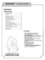
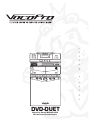
l
a
u
n
5-BAND STEREO EQUALIZER
a
TUNING
o
w
n
e
r
'
s
m
MULTI FORMAT DIGITAL KARAOKE SYSTEM
DVD-DUET
Digital Key Control DVD/CD/CDG
Dual Cassatte Karaoke System
DVD-DUET
Digital Key Control DVD/CD/CDG
Dual Cassette Karaoke System
CONTENTS
INTRODUCTION
Safety Instructions ......................................... 3
FCC Information ............................................. 4
Welcome ........................................................ 5
Listening for a Lifetime................................... 6
Before Getting Started .................................... 7
Front Panel Descriptions .............................8-9
Rear/Top Panel Descriptions ........................ 10
Remote Operations....................................... 11
Audio Controls ............................................. 12
Cassette deck operations.............................. 13
Cassette Tape/Deck Maintenance ................. 14
Connecting to external components ........15-17
System setup menu...................................... 18
Language/audio/video setup menus ............. 19
Troubleshooting ........................................... 20
Specifications ............................................... 21
FEATURES:
• 40W + 40W Maximum Power Output
• Top Loading Digital Shock Resistant
DVD/CD/CDG Player
• Dual Cassttee Decks Tto Play and Record Live
Performances Mixes from CD or Cassette
• AM/FM Stereo Tuner
• 12-Step Digital Key Controller (half-steps)
• Professional Digital Echo
• Two Microphone inputs with Individual Volume
Controls
• 5-Band Graphic Equalizer
• Stereo 4-Speaker System
• PAL/NTSC Switchable
• +/- Pitch Control for Customizing CD+G and
Tape Playback Speeds, allowing You to
Perform at Your Own Pace
2
Safety Instructions
8. Ventilation - The appliance should be situated so its
location does not interfere with its proper ventilation. For
example, the appliance should not be situated on a bed,
sofa, rug, or similar surface that may block the
ventilation slots.
CAUTION
RISK OF SHOCK
9. Heat - The appliance should be situated away from
heat sources such as radiators, heat registers,
stoves, or other appliances (including amplifiers)
that produce heat.
CAUTION: To reduce the risk of electric shock,
do not remove cover (or back). No userserviceable parts inside. Only refer servicing to
qualified service personnel.
10. Power Sources - The appliance should be
connected to a power supply only of the type described
in the operating instructions or as marked on the
appliance.
Explanation of Graphical Symbols
The lightning flash & arrowhead
symbol, within an equilateral triangle,
is intended to alert you to the
presence of danger.
11. Grounding or Polarization - Precautions should be
taken so that the grounding or polarization means of
an appliance is not defeated.
12. Power-Cord Protection - Power-supply cords
should be routed so that they are not likely to be walked
on or pinched by items placed upon or against them,
paying particular attention to cords at plugs,
convenience receptacles, and the point where they exit
from the appliance.
The exclamation point within an
equilateral triangle is intended to alert
you to the presence of important
operating and servicing instructions.
WARNING
13. Cleaning - Unplug this unit from the wall outlet
before cleaning. Do not use liquid cleaners or
aerosol cleaners. Use a damp cloth for cleaning.
To reduce the risk of fire or electric shock, do
not expose this unit to rain or moisture.
14. Power lines - An outdoor antenna should be
located away from power lines.
1. Read Instructions - All the safety and operating
instructions should be read before the appliance is
operated.
15. Nonuse Periods - The power cord of the appliance
should be unplugged from the outlet when left unused
for a long period of time.
2. Retain Instructions - The safety and operating
instructions should be retained for future reference.
16. Object and Liquid Entry - Care should be taken so
that objects do not fall and liquids are not spilled into the
enclosure through openings.
3. Heed Warnings - All warnings on the appliance and in
the operating instructions should be adhered to.
17. Damage Requiring Service - The appliance should
be serviced by qualified service personnel when:
4. Follow Instructions - All operating and use
instructions should be followed.
A.
B.
C.
D.
The power supply cord or plug has been damaged; or
Objects have fallen into the appliance; or
The appliance has been exposed to rain; or
The appliance does not appear to operate normally
or exhibits a marked change in performance; or
E. The appliance has been dropped, or the enclosure
damaged.
5. Attachments - Do not use attachments not
recommended by the product manufacturer as they may
cause hazards.
6. Water and Moisture - Do not use this unit near water.
For example, near a bathtub or in a wet basement and
the like.
18. Servicing - The user should not attempt to service
the appliance beyond that described in the operating
instructions. All other servicing should be referred to
qualified service personnel.
7. Carts and Stands - The appliance should be used
only with a cart or stand that is recommended by the
manufacturer.
Note:
To CATV system installer's (U.S.A.): This reminder is
provided to call the CATV system installer's attention to
Article 820-40 of the NEC that provides guidelines for
proper grounding and, in particular, specifies that the
cable ground shall be connected as close to the point of
cable entry as practical.
7 A. An appliance and cart combination
should be moved with care. Quick stops,
excessive force, and uneven surfaces may
cause an overturn.
3
FCC INFORMATION (U.S.A.)
1. IMPORTANT NOTICE: DO NOT MODIFY THIS
UNIT!: This product, when installed as indicated in the
instructions contained in this manual, meets FCC
requirements. Modifications not expressly approved by
Vocopro may void your authority, granted by the FCC,
to use this product.
2. IMPORTANT: When connecting this product to
accessories and/or another product use only high
quality shielded cables. Cable(s) supplied with this
product MUST be used. Follow all installation
instructions. Failure to follow instructions could void your
FCC authorization to use this product in the U.S.A.
CAUTION:
READ THIS BEFORE OPERATING YOUR UNIT
1. To ensure the finest performance, please read this
manual carefully. Keep it in a safe place for future reference.
2. Install your unit in a cool, dry, clean place - away from
windows, heat sources, and too much vibration, dust,
moisture or cold. Avoid sources of hum (transformers, v
motors). To prevent fire or electrical shock, do not expose to
rain and water.
3. Do not operate the unit upside-down.
3. NOTE: This product has been tested and found to
comply with the requirements listed in FCC Regulations,
Part 15 for Class "B" digital devices. Compliance with
these requirements provides a reasonable level of
assurances that your use of this product in a residential
environment will not result in harmful interference with
other electronic devices. This equipment
generates/uses radio frequencies and, if not installed
and used according to the instructions found in the
owner's manual, may cause interference harmful to the
operation of other electronic devices. Compliance with
FCC regulations does not guarantee that interference
will not occur in all installations. If this product is found
to be the source of interference, which can be
determined by turning the unit "Off" and "On", please try
to eliminate the problem by using one of the following
measures:
4. Never open the cabinet. If a foreign object drops into the
set, contact your dealer.
Relocate either this product or the device that is being
affected by the interference.
9. This unit consumes a fair amount of power even when the
power switch is turned off. We recommend that you unplug
the power cord from the wall outlet if the unit is not going to
be used for a long time. This will save electricity and help
prevent fire hazards. To disconnect the cord, pull it out by
grasping the plug. Never pull the cord itself.
Use power outlets that are on different branch (circuit
breaker or fuse) circuits or install AC line filter(s).
In the case of radio or TV interference, relocate/reorient
the antenna. If the antenna lead-in is 300-ohm ribbon
lead, change the lead-in to coaxial type cable.
If these corrective measures do not produce satisfactory
results, please contact your local retailer authorized to
distribute Vocopro products. If you can not locate the
appropriate retailer, please contact Vocopro, 1728
Curtiss Court, La Verne, CA 91750.
5. Place the unit in a location with adequate air circulation.
Do not interfere with its proper ventilation; this will cause the
internal temperature to rise and may result in a failure.
6. Do not use force on switches, knobs or cords. When
moving the unit, first turn the unit off. Then gently disconnect
the power plug and the cords connecting to other
equipment. Never pull the cord itself.
7. Do not attempt to clean the unit with chemical solvents:
this might damage the finish. Use a clean, dry cloth.
8. Be sure to read the "Troubleshooting" section on common
operating errors before concluding that your unit is faulty.
10. To prevent lightning damage, pull out the power cord
and remove the antenna cable during an electrical storm.
11. The general digital signals may interfere with other
equipment such as tuners or receivers. Move the system
farther away from such equipment if interference is
observed.
NOTE:
Please check the copyright laws in your country
before recording from records, compact discs,
radio, etc. Recording of copyrighted material may
infringe copyright laws.
CAUTION
The apparatus is not disconnected from the AC power
source so long as it is connected to the wall outlet,
even if the apparatus itself is turned off. To fully insure
that the apparatus is indeed fully void if residual power,
leave unit disconnected from the AC outlet for at least
fifteen seconds.
Voltage Selector (General Model Only)
Be sure to position the voltage selector to match the
voltage of your local power lines before installing the
unit.
240V
120V
4
Welcome...
And Thank you for purchasing the DVD-DUET from VocoPro, your ultimate choice in
Karaoke entertainment! With years of experience in the music entertainment business,
VocoPro is a leading manufacturer of Karaoke equipment, and has been providing
patrons of bars, churches, schools, clubs and individual consumers the opportunity to
sound like a star with full-scale club models, in-home systems and mobile units. All our
products offer solid performance and sound reliability, and to reinforce our commitment
to customer satisfaction, we have customer service and technical support professionals
ready to assist you with your needs. We have provided some contact information for
you below.
VocoPro
1728 Curtiss Court
La Verne, CA 91750
Toll Free: 800-678-5348
TEL: 909-593-8893
FAX: 909-593-8890
VocoPro Company Email Directory
Customer Service & General Information
[email protected]
Tech Support
[email protected]
Remember Our Website
Be sure to visit the VocoPro website www.vocopro.com for the latest information on
new products, packages and promos. And while you're there don't forget to check out
our Club VocoPro for Karaoke news and events, chat rooms, club directories and even
a KJ Service directory!
We look forward to hearing you sound like a PRO, with VocoPro, your ultimate choice in
Karaoke entertainment.
FOR YOUR RECORDS
Please record the model number and serial number below, for easy reference, in case of loss or theft. These
numbers are located on the rear panel of the unit. Space is also provided for other relevant information
Model Number
Serial Number
Date of Purchase
Place of Purchase
5
Listening For A Lifetime
Selecting fine audio equipment such as the unit you've just purchased is only the start of your musical enjoyment. Now it's
time to consider how you can maximize the fun and features your equipment offers. VocoPro and the Electronic Industries
Association's Consumer Electronics Group want you to get the most out of your equipment by playing it at a safe level.
One that lets the sound come through loud and clear without annoying blaring or distortion and, most importantly, without
affecting your sensitive hearing.
Sound can be deceiving. Over time your hearing 'comfort level' adapts to a higher volume of sound. So what sounds
'normal' can actually be loud and harmful to your hearing. Avoid this by setting your equipment at a safe level BEFORE
your hearing adapts.
To establish a safe level:
• Start with your volume control at a low setting.
• Slowly increase the sound until you can hear it comfortably and clearly, and without
distortion.
Once you have established a comfortable sound level:
• Set the dial and leave it there.
• Pay attention to the different levels in various recordings and adjust when necessary.
Taking a minute to do this now will help to prevent hearing damage or loss in the future. After all, we want you listening for
a lifetime.
Used wisely, your new sound equipment will provide a lifetime of fun and enjoyment. Since hearing damage from loud
noise is often undetectable until it is too late, this manufacturer and the Electronic Industries Association's Consumer
Electronics Group recommend you avoid prolonged exposure to excessive noise. This list of sound levels is included for
your protection.
Some common decibel ranges:
Level
30
40
50
60
70
80
Example
Quiet library, Soft whispers
Living room, Refrigerator, Bedroom away from traffic
Light traffic, Normal Conversation
Air Conditioner at 20 ft., Sewing machine
Vacuum cleaner, Hair dryer, Noisy Restaurant
Average city traffic, Garbage disposals, Alarm clock at 2 ft.
The following noises can be dangerous under constant exposure:
Level
90
100
120
140
180
Example
Subway, Motorcycle, Truck traffic, Lawn Mower
Garbage truck, Chainsaw, Pneumatics drill
Rock band concert in front of speakers
Gunshot blast, Jet plane
Rocket launching pad
-Information courtesy of the Deafness Research Foundation
6
Before Getting Started:
Things to Consider
It is very important to read the following instructions prior tofirst use of you DVD-DUET. Doing so will ensure proper operation and may save you
some time as well.
Protect Against Power Surges
• Connect all external components before you plug any of their power cords into the wall outlet.
• Turn off the DVD-Duet before you connect or disconnect any cables.
• Make sure all cables are properly grounded.
Protect Components from Overheating
• Don’t block ventilation holes. Arrange any components so that air can circulate freely.
• Don’t stack components.
• If you place the DVD-Duet on a stand, make sure you allow adequate ventilation.
Position Cables Properly to Avoid Audio Interference
• Insert each cable firmly into the designated jack.
• If you place components above the DVD-DUET, route all cables down the side of the back of the
DVD-DUET instead of straight down the middle of the back of the DVD-DUET.
Important Stand and Base Safety Information
Choose the location for your DVD-DUET carefully. If the DVD-DUET is placed on a stand or base, ensure that it is of adequate size and strength to
prevent it from being accidentally tipped over, pushed off, or pulled off. This could cause personal injury and/or damage to the DVD-DUET.
You should have received the following items:
ITEMS:
DVD-DUET
SEMI-PRO Microphones
Microphone Cables
RCA Patch cable
Remote Control
QUANTITY:
(1)
(2)
(2)
(1)
(1)
5-BAND STEREO EQUALIZER
TUNING
POWER
MULTI FORMAT DIGITAL KARAOKE SYSTEM
1
DVD
STAND BY
TITLE
DVD
DIGEST
P/N
AUDIO
SUB-T
ANGLE
GOTO
PBC OFF
DISPLAY
MUTE
SET UP
ENTER
VOL
KEY
L/R
1
2
3
5
6
7
9
0
10
SLOW
REPEAT
A-B
SHUFFLE
RESUME
PROGRAM
4
8
CLEAR
STEP
ZOOM
7
2
Front Panel Descriptions
1. POWER - Press to turn the system ON, press again
and release to turn the system OFF.
13
2. CASSETTE CONTROLS.
RECORD - Press to RECORD. Refer to “Recording
Cassettes”.
PLAY – Press to PLAY tape. Refer to “Playing
Cassettes”.
REW/REV – Press to REWIND tape.
FF/CUE – Press to rapidly ADVANCE tape.
STOP/EJECT – Press to STOP cassette. (Cancels
any depressed cassette button except PAUSE).
Press again to OPEN cassette door.
PAUSE – Press to temporarily PAUSE the tape
movement in PLAY or RECORD MODE. Press
and release to start the tape moving again.
4
5-BAND STEREO EQUALIZER
3
1
TUNING
POWER
5
MULTI FORMAT DIGITAL KARAOKE SYSTEM
1
2
2
6
12
3. GRAPHIC EQUALIZER - Adjust these controls
to provide the sound quality that you prefer. Refer to
“Audio Controls.”
11
10
9
7
8
4. FUNCTION SELECTIONS – Select the INPUT
source by sliding knob to choose the desired function.
AM – for AM reception.
FM – for FM reception.
TAPE – for cassette operation.
DISC – for all disc operation.
5. TUNING – Turn the knob to choose the AM or FM
station you want.
6. MIC 1 INPUT – Connect 1/4” microphone cable here.
7. MIC 1 VOL – Turn clockwise to increase volume control and counter-clockwise to decrease.
8. MIC 2 VOL - Turn clockwise to increase volume control and counter-clockwise to decrease.
9. MASTER VOL – Adjust the control for desired VOLUME level. Turn clockwise to increase and counter-clockwise to decrease.
10. DIGITAL ECHO – Adjust the control for desired ECHO efffect level. Turn clockwise to increase and counter-clockwise to decrease.
11. BALANCE – Adjust the control for desired MUSIC /VOCAL and LEFT/RIGHT balance/. Turn clockwise to send balance to right channel and
counter-clockwise to send balance to left channel.
12. MIC 2 INPUT – Connect 1/4” microphone cable here.
7
DISC CONTROLS
13, PLAY/PAUSE - Press button to initiate disc playback. To stop disc playback momentarily, press PLAY/PAUSE again. With DVDs and other
video discs, the scene in which you paused remains on-screen. To resume playing the disc, press the PLAY/PAUSE button again.
8
Front Panel Descriptions
DISC CONTROLS CONTINUED
15
14. STOP - Press once to put player on standby in
“PRE-STOP” mode. With DVDs, VCDS and other video
discs, this standby STOP mode will not send disc output
to your monitor (VocoPro screen will appear instead),
until PLAY is pressed to resume playback. With
many types of discs, playback will resume at the point
when PRE-STOP was initiated. Pressing STOP again will
completely stop the player without saving a time marker.
With some CDGs, STOP completely cancels playback.
16
14
19
17
18
20
5-BAND STEREO EQUALIZER
TUNING
POWER
15. F.F.____- To advance the CD to the beginning of
the next track, press and release this button. Continue
pressing to advance to subsequent tracks.
MULTI FORMAT DIGITAL KARAOKE SYSTEM
1
2
16. REW____- To reverse the CD to the beginning of
the last track, press and release the button. The
player will skip back to the beginning of the track.
Continue pressing the button if you want to REWIND
to the beginning of previous tracks.
17. REPEAT– Press the REPEAT button once and
the REPEAT symbol (
) will appear on the disc display. The
disc player will repeat the track currently playing until the
STOP button is pressed. If you want to repeat play of an
entire disc indefinitely, press the REPEAT button twice and
the “ALL” will light on the display next to the REPEAT
symbol. The player will repeat playing the disc continuously
until the STOP button is pressed.
18. DISPLAY – Press DISPLAY button to display the track
number that is playing, elapsed time, number of
remaining tracks, and duration of disc that is being played.
19. MULTIPLEX – Switch between STEREO, MONO L or MONO R output with MULTIPLEX media for adding/removing guide vocals.
20. DIGITAL KEY CONTROLLER – Raises or lowers the key of the disc output in half-step increments without changing the tempo to
match the natural range of your singing voice. Operate by pushing the desired + (UP/#/SHARP) or - (DOWN/b/FLAT) while disc is playing, until
the desired key is reached. Pressing the center square button will return music to it’s original or “NATURAL” key.
NOTE : Key Controller is inoperable when AM, FM or TAPE is selected.
21. REMOTE CONTROL SENSOR
15 f t
9
Rear/Top Panel Descriptions
23
AUDIO
OUT
22
COMPONENT VIDEO OUT
Y
Cb
Cr
25
L
30
FM ANTENNA
300
R
MUSIC
ONLY
COAXIAL
VIDEO
S-VIDEO
OPTICAL
L
AUDIO
R
OUTPUT
28
29
27
27
22
26
MUSIC + MIC
23
25
21
26
21. OPEN/CLOSE – Press the OPEN/CLOSE point
to open the CD compartment. Close CD
compartment by pressing this button again.
22. FM ANT TERMINAL – Connect the FM
ANTENNA wire for optimal reception.
23. COMPONENT VIDEO OUTPUT – Connect jack to
component VIDEO IN of TV.
24. AC CORD – Plug AC power cord into compatible AC
24
31
wall outlet.
WARNING: PLUGGING THIS UNIT INTO AN AC OUTLET WITH A POWER RATING DIFFERENT
FROM THAT SELECTED ON THE VOLTAGE SELECTOR CAN SEVERELY DAMAGE THE UNIT, AND
MAY VOID YOUR PRODUCT WARRANTY.
120V
240V
25. S-VIDEO-CONNECT Jack to S-VIDEO-IN of your TV
24
26. VIDEO OUTPUT- Connect to standard VIDEO-IN on TV
27. COAXIAL- Connect to DOLBY DIGITAL AC-3 or DTS reciever/decoder
28. OPTICAL– Use this jack only when AC power is not available. Be sure to use a UL or CE approved car adapter
or a UL or CE approval AC/DC adapter.
29.AUDIO PRE-OUT – NTSC/PAL system select switch. Switch to NTSC for U.S. TV systems. Switch to PAL for European TV
systems.
30. DVD AUDIO OUTPUT – Connect this jack to the AUX input or CD input of your home audio system. The DVD player can be
listened to through your own stereo system or larger external system.
31. VOLTAGE SELECTOR– Selects between 120V-240V power settings. Ensure that the Voltage Selector is set to match the
power rating of your AC outlet before powering on the unit. Select 120V for North American-based power settings and 240V for
European-based power settings.
10
Remote Operations
2
10 Enables/disables PBC (playback control) mode. If PBC is ON,
you have direct access to tracks/scenes by using NUMBER pad with
compatible discs only. If discs are incompatible with this feature,
pressing PBC button will cause disc playback to stop and restart.
11 Selects On Screen DISPLAY language or TRACK/TIME information depending on disc type and disc options
12 To MUTE all audio output
13 To FAST REVERSE a TRACK/SCENE. Press
repeatedly to increase speed 2X, 4X, 8X up to 20X
14 To FAST FORWARD a TRACK/SCENE. Press
repeatedly to increase speed 2X, 4X, 8X, up to 20X
15 DIRECTION keys for navigating through menus
16 ENTER to confirm menu selections
17 To TRACK REVERSE to previous TRACK/SCENE
18 To go TRACK FORWARD to next TRACK/SCENE
19 Disc PLAY, PAUSE and STOP function keys. When a DVD is
stopped, the VocoPro screen appears and player first enters
PRE-STOP mode, allowing playback at the same point when PLAY or
RESUME (see #30) is pressed. Pressing STOP again will cancel this
standby mode and completely stop the disc player.
20 VOLUME controls + (up) /- (down) for disc audio output
21 L/R key selects between MONO L/R (duplicates either side in
both channels) for use with Multiplex media or STEREO audio output
for standard
22 KEY CONTROL allows you to adjust source music 12 steps +
(#) or - (b) from Natural ( ) note
23 Disc program/track selection NUMBER PAD; For doubledigit track numbers, use +10 key plus addition numeral where
applicable.
24 To CLEAR selections made in menus
25 Allows you to SLOW playback speed 1/2, 1/3, 1/4, 1/5, 1/6 up
to 1/7 of original speed
26 You can choose REPEAT 1 track or REPEAT ALL tracks
using this button.
27 A-B is used to repeat a specific portion of a disc as a loop for
pratice or fun. Press A-B once to select starting point, then press
A-B again to set end point of your loop. The loop you have created
willplay indefinitely until you press A-B a final time to cancel.
28 STEP allows you to pause view and advance frame-by-frame for
detailed viewing.
29 With SHUFFLE, you can toggle RANDOM ON/OFF.
30 To RESUME playback after PRE-STOP/standby mode (see #19)
31 To PROGRAM CHAPTERS or TRACKS for playback; With
videos, enter TITLE:CHAPTER(s) desired using DIRECTION keys and
NUMBER PAD, then arrow down to PLAY and press ENTER. For
audio, enter TRACK numbers in order desired.
32 Allows you to ZOOM 2X, 3X, 4X, 1/2, 1/3, or 1/4 the size of
original picture
3
4
1
DVD
STAND BY
SET UP
DVD
DIGEST
TITLE
5
9
P/N
AUDIO
SUB-T
ANGLE
GOTO
PBC OFF
DISPLAY
MUTE
6
7
10
8
11
12
13
14
ENTER
15
16
17
18
20
VOL
19
21
KEY
L/R
22
23
1
2
3
4
5
6
7
8
9
0
10
SLOW
REPEAT
A-B
SHUFFLE
RESUME
PROGRAM
CLEAR
24
25
STEP
29
30
31
26
27
ZOOM
28
32
1 DVD STANDBY will return to the beginning of disc and
until hold until button is released released
2 Displays SYSTEM SETUP menu
3 TITLE manual select for DVDs
4 With DVDs, returns to main DVD DIGEST menu
5 P/N toggles between PAL and NTSC video formats
6 With DVDs, selects SOUNDTRACK mode
7 SUB-T displays SUBTITLES menu for selection
8 ANGLE selects between different viewing angles with
compatible discs for theatrical performances, sports events or
other live recordings
9 GOTO is used to input CHAPTER, SCENE or TIME with DVDs
11
Audio Controls
Graphic EQ Settings
After choosing the program source you want; adjust the GRAPHIC EQUALIZER controls as follows:
1. Adjust the VOLUME control for the desired listening level.
2. Set the GRAPHIC EQUALIZER controls to match the sound characteristics of your listening room. With each of the five controls of the GRAPHIC
EQUALIZER, it is possible to control a narrow, distinct section of the audio band by up to +/-10dB. The frequency bands controlled by the slide
controls have been chosen to give you the best possible control action within the audio spectrum.
100 Hz -Is very useful for enhancing low bass notes (as in organ music, kick drum, etc.) or making corrections when a deficiency in bass exists. Or
you can use this to reduce rumble, acoustic feed back, and other low frequency aberrations.
300 Hz -Will allow you to vary the upper bass frequencies. An over-accentuated, upper bass will give a muddy, boom quality to music while the
system shy of upper bass will sound hollow and thin.
1 kHz - Lies in range of frequencies where the ear is most sensitive to tonal balance. This is often called “presence”, since adjusting this control brings
the vocalist out to the front or back into ensemble.
3. 3 kHz-Speaker designers often boost output in this range to effect a quality of presence to the music. Too much energy on the other hand, sounds
overbearingly harsh and stringent.
10 kHz -Adjustment affects the brilliance of music with too much boosts in high frequencies (can be an unpleasant and piercing quality). You may use
this to add a little more dimension to the high-shelf sound or use it as a very high frequency noise filter.
Using Your Radio
AM or FM - Press the POWER button ON. Slide the FUNCTION SELECTOR to AM or FM. Rotate the tuning knob to the desired listening station.
(Fig. 1)
Cassette Handling
Operating Tips
1. High quality tapes will give you better recordings. Tapes of the following types are suggested: Low noise, high density, high output or extended
range with a play or record time up to 90 minutes.
NOTE: Cassette with a time of 120 minutes (C120) are not recommended because they contain thinner and longer tapes which are more likely
to jam or tangle in the player/recorder.
2. For best results in playing or recording, it is necessary for the head to be clean. Refer to cleaning instructions. Keep cassettes away from
excessive heat or cold.
3. If the tape is loose in the cassette, tighten it before putting it in.
To do so, put a pencil into the hub and turn it to the right
(Shown in Fig. 1)
(Fig. 1)
4. A leader tape begins each side of a cassette. You cannot play or
record on this part of the tape. You have to let the tape run for
about five seconds so this leader tape is past the heads.
NOTE: When you start the tape, be sure the tape take–up reel is moving.
If the reel is not moving stop the machine at once; if you don’t the tape could become tangled in the player/recorder. If this does hap
pen, carefully remove the cassette and correct it as shown above.
12
Cassette Deck Operations
Follow the steps bellow for any tape deck operations:
1. Press the POWER switch ON.
2. Slide the FUNCTION SELECTOR to TAPE.
3. Press the STOP/EJECT button, the cassette door will open.
4. Put the cassette into the holder, open end down, and gently close the cassette door.
5. Press the PLAY button. The system will play the cassette till the end of that side is reached. To play the other side, hit the STOP/EJECT button and
remove the cassette, turn it around and put it back in, close the door and press the PLAY button.
Extended play
Extended listening is possible by using the two cassette decks as follows:
1. Press the POWER switch ON.
2. Slide the FUNCTION knob to TAPE.
3. Load a cassette into both decks.
4. First, press the PLAY button on the Deck 2, and then press the PAUSE and PLAY buttons on Deck 1(in that order). Deck 2 will play its cassette first
and stop at its end, at that time, Deck 1 will automatically begin playback.
Recording Cassettes
1. Press the POWER button ON.
2. Select your master source signal to be recorded by sliding the FUNCTION SELECTOR control to AM, FM, CD or TAPE. You will (though internal
connections) record the source you are listening to. The recording level is not affected by the master volume control.
3. Press the STOP/EJECT button on the Deck 1; the cassette door will open.
4. Put the cassette into the holder open the end down and gently close the cassette door.
5. With a partially recorded tape, use the FAST FORWARD and REWIND controls to find your starting point.
6. Remember to advance past the leader when using a new tape.
7. Press the PAUSE button.
8. Press the RECORD button firmly.
9. When you are ready to start your recording, press and release the PAUSE button.
10. The system will record the entire cassette and shut off unless you desire to stop it by pressing the STOP/EJECT or PAUSE button.
11. Press the PAUSE button to stop the tape for a time while you change your recording selection, cue a record or retune a radio station. Press and
then release PAUSE when you are ready to continue recording.
12. While you are recording, you may monitor the program by listening to the speakers. Adjust the VOLUME control for your best listening level. It will
not affect the record level.
Sync Dubbing
1. Press the POWER button ON.
2. Press the STOP/EJECT button; the cassette door will open.
3. Load a blank tape into Deck 1. Gently close the cassette door. First press PAUSE, and then press RECORD.
4. Load the tape to be copied into Deck 2. Gently close the cassette door.
5. Press the PLAY button on Deck 2. The PAUSE button on Deck 1 will release and recording will begin.
13
Cassette Tape/Deck Maintenance
Erase Protection
Every cassette can be protected against accidental erasing of
pre-recorded material. On the back of a cassette are two
breakout tabs. These must be in place before the RECORD
button will depress. If these tabs have been removed,
such as on pre-recorded cassette you buy, the RECORD
button will not depress. To record using a cassette which
has the breakout tabs removed, place a piece of tape over
the exposed holes, this will allow the interlocking device
to engage
Far Side 1(A)
Near Side 2(B)
Break tab
Once you have made a recording, you can prevent an accidental erasing by breaking out and removing the tabs. With side 1(A) facing you, erasing is
prevented by breaking out the tab on the right, and side 2(B) by the tab on the left (see drawing).
Cleaning
To prevent fire or shock hazard, disconnect your stereo system from the AC power plug when cleaning.
• The finish on our stereo may be cleaned with a dust cloth and cared for as other furniture. Be careful when cleaning and wiping the plastic parts.
Mild cleaners, such as dishwashing detergent, with dampened (not wet) cloth may be used on the front panel.
Tape Deck Cleaning
• To get the best sound from your tapes, the pressure roller, capstan, play/record and erase heads should be cleaned regularly. The build up of
iron oxide particles is often severe with inferior tapes and will reduce the performance or the system. After every 100 hours of use, or more often if
playback has become poor, clean the play/record and erase heads, capstan and pressure roller. To clean them, wipe dry with a soft, clean cloth.
Cassette Record/Playback
Erase
Head
Play/Record
Head
Cassette Playback
Pressure Capstan
Roller
Tape
Guard
play
head
Pressure
Roller
Capstan
NOTE: Never use any metal objects on or near the tape head. Do not allow any cleaning material to fall into tape assembly. Do not use carbon tetrachloride as a cleaning agent..
14
Getting Connected to External Components
AUDIO
OUT
Connecting to an analog amplifier/
2-channel stereo receiver/mixer
COMPONENT VIDEO OUT
Y
Cb
Cr
L
Using the supplied RCA patch cable, connect
one set of red & white RCA plugs to the RCA
AUDIO OUTPUT jacks on the DVD-DUET
Connect the other set of red & white RCA
plugs to the AUDIO INPUT jacks on your
stereo receiver/TV. Depending on the stereo
receiver/TV, the audio input jacks may be
labeled AUDIO, LINE, AUX, VIDEO 1/2/3.
R
MUSIC
ONLY
COAXIAL
VIDEO
S-VIDEO
OPTICAL
L
AUDIO
R
OUTPUT
MUSIC + MIC
Stereo Channel
Stereo receiver/TV
AUDIO
OUT
COMPONENT VIDEO OUT
Y
Cb
Cr
L
R
MUSIC
ONLY
COAXIAL
VIDEO
S-VIDEO
OPTICAL
MUSIC + MIC
Connecting to a TV with an RCA Connection
Using either the yellow-ended RCA plug from the included RCA patch cable or a separate RCA patch cable,
connect one end to the RCA VIDEO OUTPUT jack on the DVD-DUET and connect the other end to the VIDEO
INPUT jack on our TV or monitor device.
AUDIO
OUT
COMPONENT VIDEO OUT
Y
Cb
Cr
L
R
MUSIC
ONLY
COAXIAL
VIDEO
S-VIDEO
OPTICAL
L
AUDIO
R
OUTPUT
MUSIC + MIC
Connecting to a TV with an RF Modulator
If your TV has only a RF-style Jack, such as Antenna In or 75 ohm, and no RCA video input jack, you can
connect video with a RF modulator (not supplied). Ask your dealer for details on RF modulator availability and
compatibility. Follow the instructions provided with the RF modulator to connect the DVD-DUET to your TV.
15
Getting Connected to External Components
AUDIO
OUT
COMPONENT VIDEO OUT
Y
Cb
Cr
L
R
MUSIC
ONLY
COAXIAL
VIDEO
S-VIDEO
OPTICAL
L
AUDIO
R
OUTPUT
MUSIC + MIC
VIDEO OUT
VIDEO IN
Connecting to a TV with a VCR
You can also use a VCR to connect video to a TV with no RCA video input. You will need an RCA cable and
a 75-ohm Coaxial type cable. Using the RCA video cable, connect one end to the VIDEO OUTPUT jack on
the DVD-DUET and connect the other end of the cable to the VIDEO INPUT of a VCR. Then, using the 75ohm Coaxial type cable, connect one end to the RF OUTPUT of the VCR, and connect the other end to the
75-ohm TV ANTENNA INPUT jack.
AUDIO
OUT
COMPONENT VIDEO OUT
Y
Cb
Cr
L
R
MUSIC
ONLY
COAXIAL
VIDEO
S-VIDEO
OPTICAL
L
R
OUTPUT
MUSIC + MIC
S-VIDEO IN
Connecting to a TV with S-Video
Using an S-Video cable, connect one end to the DVD-DUET’s S-VIDEO OUTPUT jack and connect the other
end to the S-VIDEO IN jack on your television. See the Video preferences directions under System Setup
mennu to select video output
AUDIO
OUT
COMPONENT VIDEO OUT
Y
Cb
Cr
L
COMPONENT VIDEO
R
MUSIC
ONLY
COAXIAL
VIDEO
S-VIDEO
OPTICAL
L
AUDIO
R
OUTPUT
MUSIC + MIC
Connecting to a TV with Component Video
Using 3 appropriate Component Video cables (usually color coded red, blue and green), connect a set of
plugs to the COMPONENT VIDEO OUT jacks (Y Cb Cr) on the DVX-680K and plug the other set of plugs to
your COMPONENT VIDEO IN jacks (Y Cb Cr) on your television. On some TVs the component video input
jacks may be labeled (Y Pb Pr). See the Video preferences directions under System Setup menu to select
video output.
16
Getting Connected to External Components
AUDIO
OUT
COMPONENT VIDEO OUT
Y
Cb
Cr
L
R
MUSIC
ONLY
COAXIAL
VIDEO
S-VIDEO
OPTICAL
L
AUDIO
R
OUTPUT
MUSIC + MIC
Connecting to a HDTV or video monitor
To connect video to a HDTV you can use the same connections as for TV with Component Video. See Video
preferences under System Setup menu for selecting video output type.
AUDIO
OUT
COMPONENT VIDEO OUT
Y
Cb
Cr
L
R
MUSIC
ONLY
COAXIAL
VIDEO
S-VIDEO
OPTICAL
L
AUDIO
R
OUTPUT
DTS
Receiver/Decoder
MUSIC + MIC
-or-
Connecting to a DTS Receiver/Decoder
Using either an RCA type COAXIAL cable for digital audio or an OPTICAL cable, connect one end to the respecitve Coaxial or Optical jack of the DUET and the other end to the appropriate jack on the DTS receiver. If
you have both coaxial and optical inputs on your DTS decoder/receiver, it is recommended to use an optical
connection as those cables eliminate the possibility of Electromagnetic Interference.
AUDIO
OUT
COMPONENT VIDEO OUT
Y
Cb
Cr
L
R
MUSIC
ONLY
COAXIAL
VIDEO
S-VIDEO
OPTICAL
L
AUDIO
R
OUTPUT
Dolby Digital AC-3
Receiver/Decoder
MUSIC + MIC
-or-
Connecting to a Dolby Digital AC-3 Receiver/Decoder
Using either an RCA type COAXIAL cable for digital audio or an OPTICAL cable, connect one end to the respecitve Coaxial or Optical jack of the DUET and the other end to the appropriate jack on the DTS receiver. If
you have both coaxial and optical inputs on your DTS decoder/receiver, it is recommended to use an optical
connection as those cables eliminate the possibility of Electromagnetic Interference.
AUDIO
OUT
COMPONENT VIDEO OUT
Y
Cb
Cr
L
R
MUSIC
ONLY
COAXIAL
VIDEO
S-VIDEO
OPTICAL
L
AUDIO
R
OUTPUT
Dolby DTS/
AC-3 Receiver
MUSIC + MIC
and
Connecting both Analog and Digital Audio
To do this you will need a Dolby Digital DTS/AC-3 receiver with analog audio inputs. Use optical for
video and digital audio and L/R RCA audio for Karaoke features.
17
System Setup Menu
SYSTEM SETUP MENU
To access your preferences settings, use the SETUP button on your
remote. Use the DIRECTION keys to navigate within this menu for the
specific subdirectory desired and press ENTER. The icon file tabs at the
top of the screen indicate which menu is highlighted.
SYSTEM SETUP
TV SYSTEM
SCREENSAVER
VIDEO
TV TYPE
PASSWORD
RATING
DEFAULT
EXIT SETUP
SYSTEM SETUP SCREEN
TV SYSTEM
NTSC
PAL 60
PAL
SCREENSAVER
VIDEO
TV TYPE
PASSWORD
AUTO
RATING
DEFAULT
EXIT SETUP
TV SYSTEM
SCREENSAVER
VIDEO
TV TYPE
PASSWORD
INTERLACE-YUV
TV-RGB
P-SCAN YPBRP
RATING
DEFAULT
S-VIDEO
EXIT SETUP
VIDEO
TV SYSTEM
SCREENSAVER
4:3 PS
4:3 LB
PASSWORD
16:9
RATING
DEFAULT
EXIT SETUP
TV TYPE
4. TV TYPE
This menu actually refers to TV display mode. Choose between 4:3PS for
Panoramic Screen, 4:3LB for Letterbox, or 16:9 based on your viewing
preference.
5. PASSWORD
The password to lock or unlock RATING setting is 0000. If you are a
parent and want to limit the types of DVDs viewed with the DVD-DUET,
type this password using the NUMBER keys on the remote, and press
ENTER. You will see the padlock icon either open or close, affecting the
ability of the user to make a selection in the RATING mode.
6. RATING
Choose between NO ADULT, KID SAFE, or VIEW ALL to designate which
types of DVDs you want users to be able to access playback for.
7. DEFAULT
Select this mode if you choose to return to all system preferences DEFAULT settings.
TV SYSTEM
SCREENSAVER
VIDEO
TV TYPE
PASSWORD
RATING
DEFAULT
NO ADULT
KID SAFE
EXIT SETUP
VIEW ALL
RATING
2. SCREEN SAVER
The DVD screen saver can be toggled ON/OFF to suit your preference for
display during periods of player inaction when power remains on. Use
DIRECTION keys to make your selection.
3. VIDEO
Refer to your TV manual to determine which type of video it supports.
You can choose between
INTERLACE-YUV, TV-RGB, P-SCAN YPBPR or S-VIDEO.
TV SYSTEM
VIDEO
TV TYPE
1. TV SYSTEM
Use this menu to set your system preferences for regional TV system
types NTSC, PAL60, PAL, or AUTO to have your DVD-DUET automatically
find any compatible TV system.
8. EXIT SETUP
Highlight this option and press ENTER at any time to exit these menus
and return to previous
operations
18
Language Setup, Audio Setup, Video Settings
LANGUAGE SETUP
Use this menu to set language preferences for each of these functions.
Use the DIRECTION keys to make a selection and press ENTER to confirm
your choice.
LANGUAGE SETUP
OSD LANGUAGE
AUDIO LANGUAGE
SUBTITLE LANGUAGE
MENU LANGUAGE
EXIT SETUP
LANGUAGE SETUP SCREEN
1. OSD (On Screen Display) LANGUAGE for remote functions, etc.
Choose between English or Chinese.
2. AUDIO LANGUAGE. This feature is dependent on the options
included with each individual disc. Choose from the list provided.
3. SUBTITLE LANGUAGE. This feature is dependent on the options
included with each individual
disc. Choose from the list provided.
4. MENU LANGUAGE. This feature is dependent on the options
included with each individual disc. Choose from the list provided.
AUDIO SETUP
1. AUDIO OUT
AUDIO SETUP
AUDIO OUT
KEY
SPDIF/OFF
SPDIF/RAW
SPDIF/PCM
AUDIO OUT
VIDEO SETUP
BRIGHTNESS
CONTRAST
HUE
SATURATION
VIDEO SETUP
With the DVD-DUET, you can output standard analog audio simultaneous with digital output by using the RCA L/R outputs and Coaxial output.
When connecting the DVD-DUET to an external sound system with digital
inputs, choose between a) SPDIF/OFF to completely bypass digital audio,
SPDIF/RAW for Dobly 5.1 or SPDIF/PCM for digital, high fidelity stereo
(2-channel) output depending on your external audio components and
connections.
2. KEY CONTROL
This feature functions exactly the same as the KEY CONTROL buttons on
the remote control, but with a virutal vertical “fader” instead of a left-right
display. Use the DIRECTION keys to locate the fader bar, raise (#/sharp) or
lower (b/flat) the output of the disc in half-step increments.
VIDEO SETUP
Use the DIRECTION keys to locate the virtual fader and raise/lower the
fader bar for each of the following video preference settings:
1. BRIGHTNESS
2. CONTRAST
3. HUE
4. SATURATION
19
Troubleshooting
If your stereo system fails to operate, carefully read these instructions. Many problem situations are caused by improper use. Listed below are the most
common ones.
Problems
Solutions
Power switched on, but no sound and no light on the
POWER LED.
Poor AC power plug connection to wall outlet.
Connect AC correctly.
Old wall-outlets sometimes cause power loss Plug
must fit snugly in outlet.
The POWER LED system is on but no sound
Poor FM reception
VOLUME control is at “0 “position.
Antenna not placed for best reception.
Adjust the VOLUME control to a proper sound
level.
Move antenna wire around to obtain best reception.
System turned on and PLAY pressed, but no sound
from TAPE.
FUNCTION SELECTOR set improperly for tape
playback.
PAUSE button pressed in.
Unrecorded tape inserted.
Slide FUNCTION SELECTOR to TAPE.
Press and release the PAUSE button.
Insert recorded tape.
Poor playback sound.
Dirty heads.
Clean heads. See TAPE DECK Cleaning.
Cassette tape is badly stretched.
Heads have become magnetized.
Replace the cassette.
Degauss the play and record head with a tape head
demagnetizer every 100 hours of use.
Cassette without erase protection tabs is inserted.
Dirty heads.
Try another cassette, or place a piece of tape over
the breakout tab holes.
Clean heads. See Tape Deck Cleaning.
Heads have become magnetized.
Degauss the play and record head with a tape head
demagnetizer every 100 hours of use.
Replace microphone or microphone cord.
RECORD button cannot be pressed in.
Poor recording.
Microphone defective
Microphone cable broken or intermittent.
Tape speed is erratic.
Cannot copy from DECK 2 to
DECK 1.
Dirty capstan and/or pressure roller.
Unrecorded tape inserted into
DECK 2.
PLAY/RECORD function selector is in wrong position.
Clean the capstan and pressure roller.
Insert recorded tape.
CD Player does not work properly.
Disc is inserted upside down.
Disc is dirty.
Disc is scratched.
Disc seriously warped.
A nonstandard disc is inserted.
Moisture has formed inside the CD deck.
Insert disc correctly.
Wide clean with soft cloth.
Use a new disc.
Use a new disc.
Use only brand name disc.
Wait about 20 to 30 minutes to let it dry.
NO song lyrics Appear on screen.
Video cable is not connected properly to the TV.
Connect the video cable to the
Duet-II VIDEO OUT and to the TV VIDEO IN.
Using your TV Remote to select VIDEO or AUX
input.
Source selector on TV is not set to VIDEO.
TV does not have video line input.
20
Set to the proper position.
Connect from VIDEO OUT of the
Duet-II to the AUX IN of your VCR of Connect to an
RF Modulator and then to the TV cable input.
Specifications
RADIO SECTION
Frequency range AM: 530 - 1719KHz
Frequency range FM: 87.5 - 108MHz
AUDIO SECTION
Output power (THD 10%): 40W + 40W peak
Output impedence: 8 Ohms
Graphic Equalizer controls: ± 10dB
CASSETTE SECTION
Frequency response: 125Hz - 8 KHz
Wow and Flutter: 0.35%
Tape speed: 4.75 cm/sec
AC Input Power: AC 120/240V; 50Hz/60KHz; 60W
CD PLAYER SECTION
Frequency response: 125Hz - 8KHz
Signal to Noise Ratio: 50dB
Wow and Flutter: immeasurable
D/A conversion: 16-bit linear
Sampling system: 2 times over sampling
DIGITAL KEY CONTROL SECTION
12 steps in half-step increments
SPEAKER SECTION
Stereo two way, four speaker system with two
4” woofers and two 1/4” tweeters
21
Vocopro 2004
V 1.0
WWW.VOCOPRO.COM
C