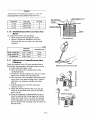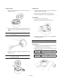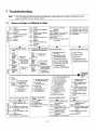
1
M9961-H13021
SERVICE MANUAL
MARINE DIESEL ENGINE
6CXM-GTE/GTE2
Literature No.
Revision history list
M9961-H13021
Page No.
1
Document name SERVICE MANUAL FOR YANMAR MARINE DIESEL ENGINE
Product name
Revision No.
Rev.1
6CXM-GTE/GTE2
Revision date
Revision outline
Revised item
(page)
Revised by
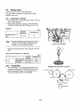
3.11 Fuel Oil System
was increased.
From page 3-29
to page 3-43-24
Marine Business
Development Dept.
Reason for revision
November, 05 To add more details of
fuel injection pump
-i-
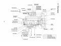
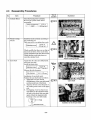
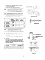
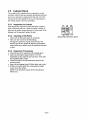
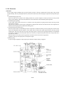
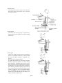
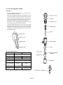
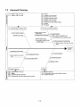
3.11 Fuel Oil System
The engine revolutions are transmitted to the camshaft by
the driving gear of the fuel pump via the timer.
The feed pump activated by the camshaft rotations sucks
fuel oil from the fuel tank and feeds it to the fuel filter at the
pressure of about 0.33 MPa (3.4 kgf/cm2).
The filtered fuel oil is sent to the oil sump in the pump
housing and is pressurized by the plunger. The fuel oil then
flows through the injection pipe and nozzle holder and is
injected from the nozzle to each cylinder.
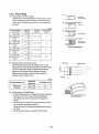
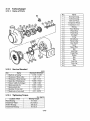
Fuel injection pump
Automatic timer
Fuel feed pump
Boost compensator
Governor
Damping valve
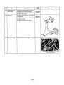
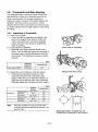
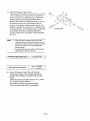
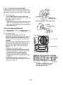
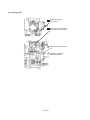
3.11.1 Fuel Injection Pump
Delivery valve
The Yanmar YPES-PS fuel injection pump is an integrated
type and the engine revolutions are transmitted to the camshaft of the pump through the driving gear and advance timer.
Plunger barrel
Plunger
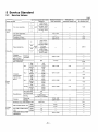
(1) Specifications
Unit
6CXM-GTE/
6CXM-GTE2
Plunger dia.
mm
13
Plunger pre-stroke
mm
3.5
mm3/st
70
Delivery valve suck-back q'ty
Delivery valve dia.
mm
7
Cam lift
mm
12
Thrust clearance
mm
0.01 - 0.05
Plunger spring free length
Plunger spring constant
Delivery valve spring free length
Delivery valve spring constant
mm
54
N(kgf)/mm
36.7 (3.74)
mm
21
N(kgf)/mm
9.26 (0.944)
Control rack
Tappet
Fuel cam
(YPES-PS type)
- 3-29 -
(2) Feature
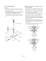
(3) Injection volume control
The fuel injection pump supplies pressurized fuel to the
injection nozzles through the action of the plunger.
The plunger reciprocates in the plunger barrel with a
fixed stroke and is lapped for a precise fit.
A lead groove is helically cut in the plunger, and this
leads to a connecting groove which rises to the top of the
plunger.
The integrate plunger barrel, the plunger barrel and the
flange case for the delivery valve holder, equips a port for
intake and discharge.
The injection volume of individual cylinders can therefore be adjusted by rotating the plunger.
The fuel comes through this port into the plunger chamber
is pressurized by the plunger, opens the delivery valve,
flows to the fuel injection nozzle through the fuel injection
pipe and is injected into the combustion chamber. Fuel
injection ends when the pressurized fuel has been discharged.
This happens when the lead groove lines up with the port,
(as the plunger rises and the pressure in the fuel injection
pipe drops).
The fuel control mechanism is shown in following fig.
The T-shaped flange at the bottom of the plunger is fixed
in the grooves of the pinion sleeve, and the pinion is
engaged to the control rack. The plunger rotates at the
same time as the control rack is moved, adjusting the
effective stroke and controlling the injection quantity.
1) Full injection volume position
When the rack is set at maximum setting, maximum
volume of fuel is discharged. Injection occurs when
the top of the plunger lines up with the intake port in
the barrel. At this time, the lead groove which is positioned at the widest stroke part, lines up with the discharge port, prolonging the injection time and
increasing the volume of fuel injected.
This setting is normally used for starting and max. output operation.
A fuel leak return hole is provided in the plunger barrel. This
returns fuel which leaks through the gap between the plunger
and the barrel to the fuel drain sump through the drain pipe,
preventing dilution of the lubricant in the cam chamber.
- 3-30 -
At the same time, the suck-back collar (1) blocks off the
fuel injection pipe and the delivery chamber, and the
valve continues descending until the seat (2) comes in
contact with the barrel.
The fuel oil pressure in the fuel injection pipe decreases
proportionately with the lowering of the valve (due to
increased volume).
This accelerates the nozzle to the nozzle valve, and sucks
up fuel from the nozzle to prevent dripping.
The result is a longer nozzle life and improved combustion efficiency.
2) Half injection volume position
Discharge ends earlier as the rack is moved towards
zero from the maximum setting.
The fuel injection volume is decreased accordingly.
3) No fuel injection
With the rack set near zero, the intake/discharge port
in the barrel is always open, so no fuel is pressurized
(even though the plunger continues to reciprocate).
(5) Injection wave damping valve
(4) Delivery valve
The delivery valve at the top of the plunger prevents fuel
in the fuel injection pipe from flowing back to the
plunger chamber and sucks up fuel from the nozzle valve
to prevent after-drip.
When plunger lead lines up with the discharge port of the
plunger barrel, the injection pressure drops, and the delivery valve is brought down by the delivery valve spring.
- 3-31 -
The injection wave damping valve is fitted inside the
delivery valve holder. This valve prevents the cylindrical
pressure from being raised again by the injection reaction
and thus prevents secondary injection and cavitation.
3.11.2 Governor
(1) Feature
The two-point weight centrifugal type all speed control governor is directly coupled with the fuel pump. The governor
weight assembly, driven by the pump shaft end, controls the control rack of the fuel pump to adjust the fuel injection quantity.
1) Condition during engine start
When the control lever is pulled to the starting position, the governor weights are closed by the force of the governor
spring, and the linkage connected to the shifter moves the control rack to the maximum injection position.
2) Conditioning during idling
As the engine starts and the control lever is returned to the idle position, the spring retainer returns and the governor
spring force is reduced.
The governor weights are opened by the centrifugal force and push the control rack to reduce the fuel. The weight force is
balanced with the spring force to maintain the idling speed.
3) Condition during maximum speed
When the engine reaches its maximum speed, the weight force is balanced with the governor spring force and the rack is
kept at the appropriate injection position. If the engine load is reduced, the engine speed increases and the governor
weights open. The rack is then moved to reduce the engine speed, to return it to the specified maximum. The maximum
fuel quantity is limited by the fuel injection limit screw. Do not try to adjust the injection limit screw except when necessary since it is sealed.
When the stop lever is turned to the stop position, the control rack is moved to the stop position,
regardless of the governor spring force, and stops the engine.
4) Damper spring
To prevent engine stoppage on sharp engine speed reduction, damper spring is equipped.
- 3-32 -
(2) Reversed angleich mechanism
The CXM model employs the high pressure fuel injection pump to match with its high output structure.
When using the high pressure pump, however, the injection volume at the equalized rack condition tends to
decrease according to the rise of engine speed. Accordingly, a larger capacity pump is used.
The use of a large capacity pump, however, gives over-torque and adverse exhaust color due to excessive fuel injection during medium speed high load operation. To prevent this and to control fuel injection volume at the medium high load operation to the proper level, the reversed angleich mechanism is used for the governor.
- 3-33 -
1) Before starting
The starting fuel increase spring let the governor
lever move to the "fuel increase" side to raise the
starting performance.
2) After starting
The starting fuel increase spring is compressed by
the thrust force of the governor to stop the starting
fuel increase.
3) Max. speed
Thrust force of the governor increases according to
the rise of revolutions and the fuel is increased until
the reversed angleich spring is completely compressed.
(This is the max. injection position.)
To explain the function more concretely, during the
medium to high load operation, even if the tension
lever contacts the fuel limiter and the rack is at the
max. position, the reversed angleich spring overcomes
the thrust force of the governor since the revolution is
below the max. speed and caused the governor level to
move to the fuel decrease side by the distance of the
control q'ty ("). This is the reversed angleich mechanism, which limits the fuel injection q'ty during
medium to high load operation for preventing "overtorque" and adverse exhaust color.
- 3-34 -
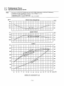
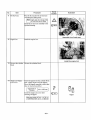
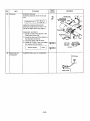
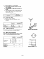
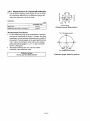
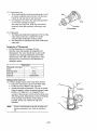
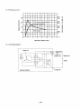
3.11.3 Boost Compensator
The boost compensator, installed to the injection pump of the turbocharged engine models, limits the movement of the fuel control rack with the boost pressure detection equipment. It optimizes fuel injection and combustion according to the air volume
inside the cylinder for complete combustion and higher output.
(1) Performance
Without boost compensator
With boost compensator
Rack position
P
R2
R3
R1
PB
PA
R0
N0
Idle
N1
N2
Engine speed
Boost pressure
Rack position and boost
pressure linear diagram
when engine speed is
raised gradually
R
Boost pressure linear diagram
at quick accelaration
1) The solid line shows the rack's moving distance and the boost pressure when the engine speed is raised gradually.
2) When the regulator handle is raised quickly from the idling position (N0) to the (N1) position, the rack moves from R0 to
R2 to attain the engine speed (N1), and injects a large quantity of fuel. The supply of air, however, is inadequate due to the
follow-up delay of the turbocharger (i.e. insufficient boost pressure), and the exhaust turns black.
3) The boost compensator limits the advancing of the rack and keeps it at R3 position. The rack starts to move at pressure of
PA and reaches to R2 position when pressure rises up to PB or more.
4) In engines with the boost compensator, injection quantity in the range of rack positions R2 - R3 (shadowed area) is limited and thus black exhaust is controlled.
(2) Equipment
When the regulator handle is operated quickly for acceleration, the control rack moves to the fuel increase side and touches
the boost compensator lever (A) to limit the rack's stroke. This position is the point where about 70% of the max. injection
quantity is obtained. (Fine adjustment is possible by the adjust screw.)
- 3-35 -
When the turbocharger catches up the engine speed and the boost pressure is raised, the diaphragm is pressed by the charging pressure, causing the boost compensator's lever to move to turn the control rack to the fuel increase side: max. injection
quantity is obtained.
- 3-36 -
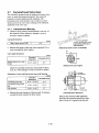
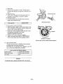
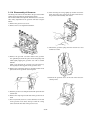
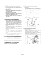
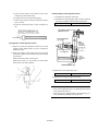
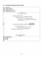
3.11.4 Disassembly of Governor
The fixing wire and seal are attached to the governor to limit
engine speed and output for protecting the engine.
Do not disassemble and adjust the limit unless it is unavoidable. Faulty adjustment of the governor will lead to engine
failure.
8) After removing the o-ring, lightly tap another end of the
shaft, and remove the governor lever shaft. Then remove
the governor shaft assembly and washer.
1) Remove the governor case cover.
2) Remove the reverse angleich mechanism.
9) Unhook the governor spring from the tension lever and
control lever shaft.
3) Remove the governor case bolt. Remove the governor
case (parallel pin) from the spacer of the fuel pump side
while lightly tapping the governor case with a wooden
hammer.
Make a gap between the governor case and spacer by
moving only the moving parts of the governor cover.
4) Remove the connecting spring by inserting needle nosed
pliers between the governor case and spacer.
10)Pull out the governor sleeve at the end of the fuel camshaft by hand.
5) Slide the governor case and pull out the link pin of the fuel
control rack.
6) Remove the snap-rings on both ends of the governor lever
shaft.
7) Put a rod (10 mm (0.3937 in.) or less diameter) on one end
of the governor lever shaft, and tap it until the O-ring
comes out from other side of the governor case.
- 3-37 -
11) Remove the governor weight nut and washer with a box
spanner, fixing the fuel camshaft by the hole of the fuel
pump coupling or holding the coupling with a vice.
Screw the governor weight nut back in two or three
times.
12)Remove the governor weight assembly from the fuel
camshaft. Use the governor pulling tools.
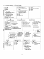
3.11.5 Inspection of governor
Inspect the following points when disassemble the governor.
Check item
Allowance
Repair
1
Wear & excessive clearance of governor
weight pin & pin hole
Within the standard clearance of 0.2mm and
Replace the governor weight cmp.
should move smoothly.
2
Contact surface of governor sleeve with
weight roller.
No excessive wear.
Replace the sleeve.
3
Thrust bearing
No seizure, discoloration, or breakage
Replace the thrust bearing.
4
Free length, fall of governor spring
Free length: Within 68 mm (Standard 65 65.5 mm)
Replace the governor spring.
5
Wear, distortion of lever shafts
No excessive clearance and distortion
Replace the shaft.
6
Oil leakage to outside
No oil oozing out and leakage
Replace the packing, O-ring.
- 3-38 -
3.11.6 Reassembly of governor
4) Mount the governor link to the governor lever assembly.
Inspect all parts after disassembly and replace any parts as
necessary. Before starting reassembly, clean both the new
parts and parts to be reused, and put them in order.
Be sure to readjust the unit after reassembly to obtain the
specified performance.
1) Insert the governor weight assembly to the taper portion at
the end of the fuel camshaft.
Fix it by the hole of the fuel pump coupling or by holding
the coupling with a vise.
Mount the conical spring washer, and tighten the governor
weight nut.
Governor weight tightening torque
Note:
1. Make sure that the correct governor link
mounting holes are used, and that it is
mounted in the correct direction.
2. Make sure that the governor link moves
smoothly.
5) Put the governor lever shaft assembly in the governor
case, insert the governor lever shaft until the O-ring
groove come out from the opposite side of the governor
case, and fit the O-ring.
59 - 69 N-m
(6 - 7 kgf-m)
Note:
2) Open the governor weight and insert the sleeve in the end
of the fuel camshaft.
1. Fit the O-ring to the side you tapped it in
from.
2. Coat the O-ring with the silicon oil for protection during insertion.
3. Don't forget to place washers on both sides of
the governor lever.
6) After mounting the O-ring, tap the governor lever in the
opposite direction, and mount the E-shaped stop rings on
the grooves at both ends.
Note:
Note:
Make sure that the sleeve moves smoothly after
insertion.
3) When the control lever shaft has been removed, lightly tap
the control lever shaft and washer from inside the governor case, using an appropriate plate.
- 3-39 -
After mounting the governor lever assembly,
make sure that it moves smoothly.
7) Hook the governor spring on the pin of the governor lever
and control lever.
8) Insert the rack link in the governor link, hook the link connecting spring on the spring pin of the governor link side
with the spring set bar, and connect the governor link with
the rack link.
9) Fit the link connecting spring to the spring pin at the rack
link with the spring set bar by pushing the rack link into
the governor link.
10)Mount the governor case to the fuel pump unit, lightly
tapping it with a wooden hammer, and tighten the bolts.
11) Mount the governor case cover.
12)Insert the control lever to the control lever shaft, and
tighten the nut.
Note:
Move the control lever back and forth to make
sure that the entire link moves smoothly.
- 3-40 -
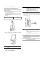
3.11.7 Disassembly of fuel injection pump
When disassembling the fuel injection pump, separate the
parts for each cylinder and be careful not to get them mixed
up.
Be especially careful to keep the plunger/plunger barrel,
delivery valve/delivery valve seat and other assemblies separate for each cylinder (the parts of each assembly must be
kept together and put them back in the same cylinder).
2) Screw the puller into the nut hole.
Remove the automatic timer by screwing in the puller
bolt.
(1) Preparation
1) Wash off the dirt and grease on the outside of the
pump with cleaning oil (kerosene or diesel oil) before
disassembly.
2) Perform the work in a clean area.
3) Remove the spring shoe setting screws of all cylinder.
3) Take off the drain plugs and drain the lubrication oil.
4) Loosen the delivery valve holders until they can be
turned by fingers.
(2) Disassembly
1) Fix the outside of the automatic timer and remove the
nut.
- 3-41 -
9) Remove the delivery valve holder, delivery valve,
valve spring, valve stopper and O-ring from the
plunger barrel.
5) Remove the plunger barrel tightening nuts.
Note:
6) Remove the plunger barrel assembly.
Insert two drivers under the barrel flange. (Be careful
not to damage the surface of the pump housing.)
Lift up the barrel by prying the driver. Pull out the barrel by turning it to and fro.
7) Remove and mark the shims to recall the original
assembly.
8) Remove the plunger and plunger barrel together with
the plunger spring and lower spring retainer.
- 3-42 -
Mark each part to recall the original assembly.
10) Remove the straight pins securing the spring shoe to
the barrel support, then remove the pinion.
15) Remove the cam support and the shims by prying
open the slots in the support with screw drivers.
11) Remove the rack setting screw and the control rack.
12) Remove the tappets.
13) Remove the fuel feed pump.
16) Remove the camshaft together with the middle bearing from the drive side.
Note:
14) Put the pump body upside down and remove the hexhollow set bolts that secure the middle bearing.
- 3-43-1 -
Be careful not to damage the governor case oil
seal when removing the camshaft.
3.11.8 Inspection of fuel injection pump
(3) Inspection of pump housing
1) Inspect the sliding surface against the tappet guide for
extreme wear. Scratches on the sliding surface against
the roller pin are not a problem.
(1) Inspection of plunger
1) Thoroughly wash the plungers, and replace the plungers that have scratches on the plunger lead or are discolored.
2) The plunger is in good condition if it slides down
smoothly when it is tilted at about 60q.
Turn the plunger and try this test several times. If the
plunger slides down too quickly or stops part way,
repair or replace it.
2) If there are burrs or discoloration, repair or replace the
body as this will lead to dilution of the lubricant.
(4) Inspection of fuel camshaft and bearings
1) Fuel camshaft
Inspect for scratches or wear of cam surface, deformation of key grooves and screw on both ends. Replace it
if necessary.
2) Replace the bearings if the outer race surface are
flaked or worn.
Note:
Replace the fuel camshaft and bearings together.
(5) Inspection of tappet
1) Inspect the surface of the tappet, roller and roller pin
for wear or damage. Replace it if necessary.
2) Measure the clearance between the roller and pin.
Replace them if the clearance exceeds 0.2mm.
(2) Inspection of delivery valve
1) Clean the delivery valve well before inspection.
Replace as a set if the collar or seat of the delivery
valve is scratched, scored, scuffed, worn etc.
(6) Inspection of rack and pinion
2) The valve is good if it returns smoothly when released
after being pushed down with your finger. (While the
hole at the bottom of the delivery guide seat is covered.) Replace it if necessary. Likewise, the valve
should completely close by its own weight when you
take your finger off the hole at the bottom of the delivery guide sheet.
(7) Inspection of plunger spring and delivery valve
spring
Note:
When fitting new parts, wash with diesel oil and
perform the above inspection.
Inspect the rack and pinion for wear and burrs on tooth
surface. Replace them if necessary.
Inspect the spring for scratches, cracks, breakage,
uneven wear and rust. Replace it if necessary.
(8) Inspection of setting screws
Inspect all setting screws and bolts for wear or damage.
Replace it if necessary.
(9) Inspection of oil seal
Inspect the oil seal lips for wear or damage. Replace it if
necessary.
- 3-43-2 -
3.11.9 Reassembly of fuel injection pump
4) Provisionally install the camshaft support.
Sure to use the standard thickness shim.
(1) Preparation
Standard thrust clearance
of camshaft
1) After inspection, arrange and clean all parts.
0.01 㨪 0.05mm
2) Prepare the parts for replacement before starting
assembly.
Note:
Note:
Always replace gaskets, packing and O-rings
with new ones.
(2) Assembly
Do not install the O-ring at this stage.
Coat the camshaft and oil seal with clean lube
oil to protect the oil seal from damage.
Take care that the shims do not stick in the Oring grooves.
1) Install the governor case to the pump housing.
2) Fit the bearings to both ends of the camshaft. Place the
pump housing upside down and insert the camshaft in
the housing together with the middle bearing.
Note:
Apply grease to the middle bearing to prevent it
from falling out before installation.
Coat the camshaft and oil seal with clean lube
oil to prevent damage to the lip of the oil seal.
5) Tighten the camshaft support with four screws.
6) Tap both ends of the camshaft with a mallet to seat the
bearings.
Turn the camshaft by hand and feel its rotating resistance (preload). If it is too heavy, adjust it by adding
shims. Remove the shim if it is too light.
3) Provisionally tighten the middle bearing with hex. hollow set bolt.
- 3-43-3 -
7) After adjusting the preload, remove the camshaft support and install new O-ring in the groove in the support.
12) Screw in the spring shoe setting bolts.
8) Apply clean lube oil to the O-rings, pump housing
bore and the camshaft support.
Note:
Be careful not to damage the O-rings.
13) Insert the rack in the pump housing and align its
ninth division of the scale with the end surface of the
pump housing thread.
9) Securely tighten the hollow set bolts of the middle
bearing.
Note:
Recheck the bearing preload after tightening the
hollow set bolts, and readjust the preload if necessary.
14) Lock the rack position with a special setting bolts as
shown below.
10) Screw in the tappet setting bolts.
11) Align the groove in the tappet with the setting bolt
and insert the tappet.
15) Install new O-ring in the plunger barrel.
- 3-43-4 -
16) Insert the plunger barrel in the deflector and barrel
collar. Align the hole in the barrel with the hole in
the collar, then set the straight pin in the holes of the
barrel and collar to fix them.
20) Hook the neck of the plunger to the spring retainer,
align the plunger flange with the slots in the pinion
and push the plunger until it is locked by the clip ring
on the pinion.
21) Place a shim around each stud bolt.
17) Insert the pinion in the spring shoe and install the
spring shoe on the barrel collar. Secure the spring
shoe with the straight pins.
22) Align the grooves in the pinion and spring shoe.
18) Insert the clip ring into the groove in the pinion.
19) Install the plunger spring.
- 3-43-5 -
23) Align the groove of the spring shoe with the setting
bolt and carefully insert the plunger barrel assembly
in the pump housing bore.
Note:
25) Install the delivery valve seat, valve, spring, stopper
and O-ring, then finger tighten the delivery valve
holder.
Apply clean lube oil to the O-rings and pump
housing bore in order not to damage the O-ring.
Do not try to drive in the barrel.
Before inserting the plunger barrel assembly,
turn the camshaft and set the cam to the position
that the tappet comes to the lowest position.
26) Align the marks on the barrel support and the pump
housing, then tighten the nuts to the specified torque.
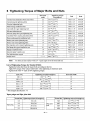
Torque
39 㨪 49 Nm (4 㨪 5 kgfm)
24) Install the original shims as marked during disassembly between the barrel and pump housing.
27) Tighten the delivery valve holders to the specified
torque.
Torque
- 3-43-6 -
98 㨪 118 Nm (10 㨪 12 kgfm)
28) Install the fuel feed pump to the pump housing.
In each case, disassemble and repair.
31) Assemble the governor.
29) Remove the rack set bolt and install the rack setting
screw securely.
32) Fill the pump and governor with clean lube oil.
Oil capacity
30) Hook a spring scale to the control rack and measure
the sliding force.
Sliding force
1472 (150 gf) max.
Excessive sliding force may be caused by the followings.
Large resistance at the sliding section of the plunger
assembly.
Excessive tightening of the delivery valve holder (distortion of the plunger barrel)
Damage or particles at the tooth of the control rack or pinion.
Damage at the outer periphery of the control rack.
Damage at the control rack hole in the pump housing.
- 3-43-7 -
pump
250 cc
governor
300 cc
3.11.10 Adjustment of fuel injection pump
4) Fill the pump and governor with clean lube oil.
oil capacity : pump
250 cc
governor 300 cc
Adjust the fuel injection pump after completing reassembly.
The pump itself must be readjusted with a special pump
tester when you have replaced major parts such as the
plunger assembly, tappet assembly, fuel camshaft, etc.
5) Connect the fuel oil pipes and operate the pump tester
to purge the air in the line.
6) Set the oil feed pressure from the pump tester to the
injection pump at the pressure specified in the separate
service data sheet.
(1) Preparation
Prepare for adjustment as follows.
1) Adjusting nozzle assembly and data sheet of injection
start pressure.
Adjusting nozzle type
Injection start pressure
See (7) Injection adjustment
standard
2) Adjusting injection pipe.
Inner dia. / outer dia. x length
Minimum bending radius
mm (in)
Ǿ6.35/1.8 600mm
25 (0.98)
3) Mount the fuel injection pump on the pump tester platform.
(2) Adjustment of pre-stroke
1) Remove the delivery valve holder of No.6 cylinder.
Remove the delivery valve spring and delivery valve.
2) Screw the pre-stroke measuring device in the screw
hole on the top of the barrel.
3) Set the control rack to the full load position.
Find the bottom dead center of the plunger while rotating the pump by hand, and set the dial indicator to
zero.
- 3-43-8 -
4) Slowly rotate the pump in the normal rotation direction by hand, and measure the plunger lift until fuel
flow from the overflow pipe on the measuring device
stops.
Pre-stroke : See separate service data
(4) Plunger pressure test
1) Mount the pressure gauge to the delivery valve holder
of the cylinder to be tested.
5) If the measured pre-stroke is not standard, adjust by
changing the shim thickness between the flange of the
plunger barrel and pump housing.
6) Repeat the above procedure to adjust the pre-stroke of
each cylinder.
7) After adjustment is completed, insert the delivery
valve, delivery valve holder and spring.
Tighten the delivery valve holder.
98 㨪 118 Nm
(10 㨪 12 kgfm)
Delivery valve holder
tightening torque
(3) Adjustment of injection timing
After adjusting the pre-stroke for all cylinders, check and
adjust the injection timing.
Count from drive coupling side
Direction of rotation
View from drive coupling side
2) Set the tester needle on the flywheel scale in a position
where it is easy to read, and check the injection timing
several times according to the injection order.
Injection order
1-4-2-6-3-5
Injection interval
60q
Allowable deviation
r 30'
0.1 mm (0.0039 in.)
Thickness of
shims
Connecting screw dimensions
M14 1.5
3) Check to see that oil is not leaking from the delivery
valve holder or fuel injection piping, and there is no
extreme drop in pressure.
(5) Delivery valve pressure test
1) Connect a pressure gauge to the delivery valve holder.
(Refer to plunger pressure test.)Drive the pump at 200
rpm and, moving the control rack, apply a pressure of
12 MPa (120 kgf/cm2).
3) Readjust the pre-stroke of cylinders that are not within
the allowable deviation (increase of the adjusting shim
thickness makes the injection timing later, and
decrease makes it earlier).
The change in injection timing by the adjusting shims
is as follows.
Adjusting thickness of shim
98.1 MPa
(1000 kgf/cm2)
2) Set the governor control lever in the stop position,
operate the injection pump at about 200 rpm, and
make sure that the pressure gauge reading is 49 MPa
(500 kgf/cm2) or more. All the time lightly move the
control rack towards fuel increase side.
Replace the plunger if the pressure does not reach this
value.
1) Set the governor control lever in the operating position
(bring the plunger to the effective injection range),
then turn the camshaft clockwise, and check the injection starting time (FID) of No.1 cylinder (start of fuel
discharge from the delivery valve holder).
Cylinder No.
Max. pressure gauge reading
Change of injection timing
Cam angle
Crank angle
0.35q
0.7q
Standard
3.0 mm (0.118 in)
Applicable
2.5 㨪 3.5 mm
(0.984 㨪 1.378 in)
(t = 0.1 mm step)
- 3-43-9 -
2) Set the control rack to the 0 mm position and measure
the time required for the pressure to drop from 10 MPa
(100 kgf/cm2) to 9 MPa (90 kgf/cm2).
Pressure drop limit
20 seconds minimum
If the pressure drops faster than this, wash the delivery
valve, and retest. Replace the delivery valve if the
pressure drop is not remedied.
(6) Measurement and adjustment of injection volume
(7) Injection adjustment standard (on engine)
The injection volume is determined by the fuel injection
pump rpm and rack position. Check and adjust to bring it
to the specified value.
1) Measurement of injection volume.
a) Set the pump rpm, rack position and measuring
stroke to the specified value and measure.
Pump rpm
See separate service data
Pump rotation direction
View from drive side
Rack indicator scale
See separate service data
b) Measure the injection volume at the standard stroke,
and adjust as follows if it is not within the specified
value.
Measuring stroke
Specified injection volume
at standard rack position
See Standard Adjustment Value
Table.
Non-uniformity of
cylinders
2) Adjustment of injection volume
a) Loosen the two nuts on the plunger barrel flange,
and turn the plunger barrel to the right or left.
b) Measure the injection volume of each cylinder.
Repeat this process until the injection volume of
every cylinder is within the specified limit.
c) After completing the measurements, retighten the
nuts of plunger barrel flange.
Tightening torque
39 㨪 49 Nm
(4.0 㨪 5.0 kgfm)
d) If match mark is not aligned, make a new match
mark.
- 3-43-10 -
Adjustment procedures
1) Set the initial rack position of the boost compensator
at R=9.0 mm.
(air pressure in the boost air pipe is 0 MPa (0 kgf/cm2).
Fuel limiter released, regulator at FULL position)
2) Check the limit rack position of the boost compensator.
R>15 [The pressure in the boost compensator piping
line increased : 0 ψ 0.2 MPa (0 ψ 2 kgf/cm2)]
3) Make the following adjustment and air leakage check
of the boost compensator piping under the air pressure
of 0.2 MPa (2 kgf/cm2).
a) Adjustment of rated injection q'ty Ԙ
b)Check of injection q'ty at idling condition. ㅜ
c) Setting of reversed "Angleich" reduced injection
q'ty. ㅝ
d) Check of injection q'ty at reversed "Angleich" range.
ޓ
㧘 e) Check of rev. speed to start reversed "Angleich". f) Setting of high idle injection q’ty. ㅠ
g)Check of regulation
h)Check of injection stop. i) Check of injection stop when the stop lever is operated. j) Check and set the injection q’ty at start. ㅥ
Standard Adjustment Value
Adjustment
Rack scale
Point
Ԙ
13.5
Average injection
q'ty (mm3/st)
Pump speed
(rpm)
6CXM-GTE
6CXM-GTE2
6CXM-GTE
6CXM-GTE2
1425
1450
197 r 3
195 r 3
(5)
350
(11.7)
1000
194 r 5
(11.0)
750
(12.4)
1175
(4)
1600
10 㨪 20
6CXM-GTE2
at 2850rpm
at 2900rpm
r3
㧙
199 r 5
㧙
Reversed angleich
(191)
(196)
㧙
㧙
(198)
measure
㧙
㧙
10 㨪 20
㧙
High idle
1625
500
110 r 5
㧙
㧙
(10)
200
190 r 10
㧙
Start
Nozzle
Nozzle holder
Nozzle opening pressure
Transfer pump pressure
Temp of fuel oil
6CXM-GTE
(9)
Nozzle holder ass'y
Fuel oil
Note
r 15
Test condition
FO injection pipe
Not uniform
%
6CXM-GTE
6CXM-GTE2
D27672-53100
D27672-53200
155S296CZ
155S306CAZ
Engine spec
Model
6CXM-GTE
㧙
6CXM-GTE2
㧙
PS-SLi
High idle
23.5 r 0.5MPa
(240 r 5kgf/cm2)
Low idle
750 r 25rpm
0.05MPa
(0.5kgf/cm2)
㧙
㧙
Ǿ6.35/1.8 600mm
㧙
㧙
Diesel oil (JIS No2 equivalent)
㧙
㧙
42 r 2 ͠
㧙
㧙
4) Make the air pressure in the boost
compensator piping to 0 MPa(0 kfg/cm2).
a) Set the reduced injection q'ty of the boost compensator. ㅣ
b) Raise the air pressure of the boost compensator gradually
from 0 MPa (0 kgf/cm2) in order to check the operation
start pressure. ㅤ , Ԙ
Make the air pressure of the boost compensator piping to
0 MPa (0 kgf/cm2).
c) Check and set the increased injection q'ty at starting. ㅥ
- 3-43-11 -
3200 r 25rpm
3250 r 25rpm
(8) Adjusting points
11 Setting of injection
q'ty at start
9 Setting of reduced injection
q'ty of boost compensator
1 Adjusting of rated injection
q'ty
4 Adjusting of stroke of
reversed "Angleich"
- 3-43-12 -
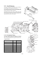
3.11.11 Fuel feed pump
(2) Double action piston and automatic pressure
control mechanism
(1) Feature
Fuel feed pump is double action piston type with four
check valves. It is installed on the side of the injection
pump and driven by a cam.
The feed pump sucks up fuel from the fuel tank and sends
it to the fuel injection pump through a fuel filter. It also
automatically adjusts the fuel delivery pressure.
Two oil seals are used on the push rod to prevent lube oil
from mixing with the fuel from entering the cam chamber.
- 3-43-13 -
When the piston moves upward, the pressure in the
upper chamber rises and the pressure in the lower chamber becomes negative. As to the check valve in the upper
chamber, right vale is closed and left valve is opened.
Thus, the fuel is delivered to the outlet.
As the pressure in the lower chamber is negative, left
valve in the lower chamber is closed and right valve is
opened, and then fuel flows into the lower chamber.
When piston moves downward, the pressure in the lower
chamber rises and left check valves are opened and right
valves are closed, and then fuel in the lower chamber is
delivered to the outlet.
When the delivery pressure of the fuel pump rises up to
the extent that the pressure at the back of the piston overcomes the piston spring force, the movement of the piston is hindered.
Thus, the fuel flow is automatically stopped, and the fuel
pressure is maintained within a fixed range.
3.11.12 Disassembly of fuel feed pump
3.11.15 Inspection after assembly
1) Remove the piston spring stopper plug and pull out the
piston spring.
1) Air leak test
Inspect the air-tightness of each pipe and packing etc.
Especially check the inlet side because air is likely to
enter due to the negative pressure of the suction.
2) Remove the piston.
3) Push the tappet from the opposite side of the plug and
remove the snap ring.
2) Leakage from inter spindle seals
Plug the outlet, apply compressed air at 0.29 MPa
through the outer port, place the feed pump in a fuel
tank and inspect for leakage from the inter spindle
seals. If there are air bubbles, replace the oil seals,
inter spindle or the feed pump body.
4) Remove the tappet and inter spindle.
5) Loosen the screw at the bottom of the priming pump
and remove the priming pump assembly.
6) Remove the inlet and outlet check valve springs and
check valves.
3.11.13 Inspection after disassembly
1) Block the inlet port of the priming pump with your finger and push in the piston. If the piston returns by the
spring force, the piston does not have enough negative
pressure. Always replace the priming pump as a set.
2) Check the piston spring for cuts, cracks, uneven wear
and rust.
3) If the piston, inter spindle, or tappet assembly is
extremely worn, replace the part.
4) Check the contact surface of the valve and valve seat
for defects.
3.11.16 Test of fuel feed pump
5) When there is play between a valve seat and feed
pump body, the whole fuel pump body must be
replaced.
6) Clean the filter screen in cleaning solvent and check it
for damage or clogging. Replace it if damaged.
Note:
Play in the valve seat hinders the opening and
closing of the valve, causing insufficient fuel
supply and abnormal wear of the tappets and
camshaft.
3.11.14 Assembly of fuel feed pump
Assemble in the reverse order of disassembly.
- 3-43-14 -
1) Setting of the pump
Set the fuel feed pump on the injection pump, and
operate the assembled unit on the pump tester.
Fuel piping should be provided directly from the tank,
not through the delivery pump of the tester.
2) Suction test for the priming pump
Loosen the handle of the priming pump, and push the
handle at 60 - 100 strokes/minute.
If fuel comes out of the delivery side of the feed pump
after about 25 strokes, the priming pump is normal. If
it takes longer, replace the priming pump as a set.
Suction head
1m
Suction pipe dia.
Ǿ13
Within 25 strokes
Delivery pressure
Pump rpm
0.40 㨪 0.55MPa (4.1 㨪 5.6 kgf/cm2)
600
Replace the piston spring if it is defective.
3) Delivery pressure test
The special equipment is necessary to perform delivery pressure and delivery volume test.
Operate the injection pump at the specified rpm, and
read the pressure gauge indicator when valve B is
tightened completely. Tighten the valve A so that the
pressure gauge indicator does not move when the pressure is applied.
Note:
Do not run the equipment for more than 5 minutes since the fuel injection pump may be damaged if operated in non-injection condition.
- 3-43-15 -
4) Delivery volume test
Operate the fuel injection pump at the specified rpm,
open valve B until the pressure gauge indicator shows
0.098 MPa (1kgf/cm2), and measure the delivery rate
for one minute.
Delivery volume
Back pressure
Pump rpm
> 4.8 "/min
0.098 MPa (1 kgf/cm2)
1000
3.11.17 Automatic timer
(1) Feature
The automatic timer controls the fuel injection timing
automatically through the centrifugal force of its rotation.
The automatic timer adjusts the advancing angle automatically as follows: - When the speed is increased, the
fly weight expands outward from the fly weight holder
under centrifugal force.
The roller installed on the fly weight moves outward
along the guide cam while compressing the timer
spring. Because the guide cam is connected directly to
the camshaft, the camshaft rotates only as far as the
timer spring has been compressed, and injection timing
is advanced.
- 3-43-16 -
(2) Disassembly
(3) Inspection
1) Remove the attaching bolts of the timer case cover to
remove the cover.
1) Check the guide cam surface for wear or damage and
replace the timer if necessary.
2) Check the roller and bush for wear and cracks.
3) Check the spring for rust, flaws and degeneration.
(4) Assembly
1) Clean all parts in cleaning solvent.
2) Install the weights and rollers in the timer case.
2) Remove the guide cam retainer from the timer case by
pushing it with a wooden bar through the timer case
hole.
Note:
Take care when removing the retainer or the
spring will pop out.
3) Install the spacers and timer case cover and tighten the
cover with two bolts.
Note:
Use new oil seals and O-rings.
(5) Installation
1) Install the timer on the camshaft of the injection pump
by aligning the key groove with the key.
2) Tighten the timer with the cap nut through the spring
washer and packing.
3) Remove the springs, weights and spring shoes from
the timer case.
Note:
Make the timer spring adjusting shims to recall
the original assembly.
- 3-43-17 -
Torque
167 㨪 196 Nm (17 㨪 20 kgfm)
3) Fill the tier with lube oil.
Oil capacity
450 cc
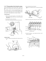
3.11.18 Fuel injection nozzle
(1) Feature
The semi-long type hole-nozzle is used with the direct
injection combustion chamber.
Fuel from the injection pump enters through the oil port
in the nozzle holder, and enters the nozzle body reservoir.
When oil reaches the specified pressure, it pushes up the
nozzle valve held by the nozzle spring, and is injected
through the small hole on the tip of the nozzle body.
The nozzle valve is automatically pushed down by the
nozzle spring and closed after fuel is injected.
Oil that leaks from between the nozzle valve and nozzle
body goes from the hole on top of the nozzle spring
through the oil leakage fitting and back into the fuel tank.
Adjustment of injection starting pressure is effected with
the adjustment bolt.
(2) Nozzle specifications
Engine model
Type
Nozzle No.
Yanmar part No.
6CXM-GTE
Semi-long type hole-nozzle
YDLL155S296CZ
YDLL155S306CAZ
127672-53000
127694-53050
Valve seat
Operating pressure
No. of injection
holes injection
hole dia
Single cone
23.5 r 0.49 MPa (240 r 5kgf/cm2)
6-0.29
Injection angle
Valve lift
6CXM-GTE2
6-0.30
155q
0.25 mm
0.30 mm
- 3-43-18 -
8) Apply lube oil to the puller bolt and screw it to the
return oil joint bolt hole of the upper injection valve
body to remove the injection valve body.
(3) Nozzle body identification number
The type of nozzle can be identified by the number on the
outside of the nozzle body.
(4) Disassembly of fuel injection nozzle
(5) Check and cleaning of fuel injection nozzle
1) Remove the bonnet fixing bolts.
2) Lift the valve slowly until it contacts the valve arm
mount (A) as shown in the illustration.
1) Check the carbon flower deposit around the injection
hole.
2) Check spray condition with nozzle tester operating the
lever 2-3 times per second.
3) Lift the (B) side with (A) as the fulcrum.
4) After removing the stud bolt fixing the bonnet (C)
from the installation hall, move the valve a little to the
reduction reversing gear side and remove the valve
completely.
5) Remove the fuel injection pipe, fuel return pipe and
fuel injection valve fixing nut.
6) Fit the fuel injection valve puller tool.
(Place the foot of the support bolt on the plane making
an right angle to the fuel injection valve.)
7) Adjust the foot length so that the puller tool body
makes a right angle to the fuel injection valve and a
distance of about 20 mm is ensured for the injection
valve.
- 3-43-19 -
No sharp angle deviation
Uniform atomized fuel
No dipping after stopping
3) Wash the nozzle in clean diesel oil with the nozzle
cleaning kit.
a) Clean off the carbon on the outside of the of the
nozzle body with a brass brush.
b) Clean the nozzle seat with cleaning spray.
c) Clean off the carbon on the tip of the nozzle with a
piece of wood.
d) Clean the nozzle hole with a nozzle cleaning needle.
(7) Reassembly of fuel injection nozzle
1) Install the fuel injection nozzle (B).
2) Install the fuel injection pipe joint to the fuel injection
nozzle (B), (together with the rubber packing (E).
Pipe joint tightening torque
24.5 Nm (2.5 kgfm)
(6) Inspection of fuel injection nozzle
1) Inspect the nozzle for abnormal scratches or wear and
replace it if the sliding surface or seat is scratched or
abnormally worn.
2) Make sure that the nozzle slides down by itself when
the nozzle is pulled out about half way from the body
and released.
Rotate the nozzle a little, and try again.
Replace the nozzle as a set if there are some places
where it does not slide smoothly.
3) Tighten the nozzle tightening nut (C).
Tightening torque
31.4 Nm (3.2 kgfm)
4) Tighten the fuel injection pipe cap nut (D).
Tightening torque
34.3 Nm (3.5 kgfm)
Caution:
* If the nozzle tightening nut (C) is tightened first, fuel oil
may leak into the lube oil.
* If the cap nut (D) is tightened first to the final torque, gas
may leak from the packing at the nozzle end.
- 3-43-20 -
3.11.19 Fuel filter
(1) Feature
The fuel filter is installed between the fuel feed pump and
fuel injection pump.
Fuel is filtered as it passes through the filter element and
the dirt/foreign matter and water from the fuel tank are
removed.
(2) Replacement of filter element
Replace the element every 250 hours of use.
Replace the element even before the provided time if the
filter interior is contaminated or damaged.
If there is water or sediment inside the filter, wash it in
clean oil and remove dust and rust completely.
Draining of filter
Every 50 hours of use
Filter element
Every 250 hours of use
Part No. of element
127695-55630
- 3-43-21 -
3.11.20 Troubleshooting of fuel oil system
(1) Before removing fuel injection pump
It is necessary to find out the cause of the trouble before
replacing the defective parts.
The cause of the trouble may not necessarily be in the
pump itself, but may be in the engine or the fuel oil system.
If the pump is removed prematurely, the cause of the
trouble may never be known.
Before removing the pump from the engine, at least go
through the basic check points given here.
Basic check points
Check for breaks or oil leaks through out the fuel system,
from the fuel tank to the nozzle.
Check the injection timings for all cylinders.
Are they correctly adjusted?
Are they too early or too late?
Check the nozzle spray.
Check the fuel delivery. Is it in good condition?
Loosen the fuel pipe connection at the injection pump
inlet, and test the operation of the fuel feed pump.
(2) Major faults and troubleshooting
Fault
Cause
1. Engine won't Fuel is not delivered (1) No fuel in the fuel tank.
start.
from injection
(2) Fuel tank cock is closed.
pump.
(3) Fuel pipe system is clogged.
(4) Fuel filter element is clogged.
(5) Air is sucked into the fuel due to defective connections in the piping from the fuel tank to fuel feed pump.
(6) Defective valve contact of feed pump
(7) Piston spring of feed pump is broken.
(8) Inter spindle or tappet of feed pump is stuck.
Remedy
Supply
Open
Clean
Replace element
Repair
Repair or replace
Replace
Repair or replace
Nozzle does not
work.
(1) Nozzle valve does not open or close normally.
(2) Nozzle seat is defective.
(3) Case nut is loose.
(4) Injection start pressure of nozzle is too low.
(5) Nozzle spring is broken.
(6) Fuel filter is clogged.
(7) Excessive oil leaks from nozzle sliding area.
Repair or replace
Repair or replace
Inspect and tighten
Adjust
Replace
Replace element
Replace nozzle assembly
Injection timing is
defective.
(1) Injection timing is retarded due to failure of the coupling.
(2) Camshaft is excessively worn.
(3) Roller guide is excessively worn.
(4) Plunger is excessively worn.
Adjust
Replace camshaft
Adjust or replace
Replace plunger assembly
2. Engine starts, but immediately
stops.
(1) Fuel pipe is clogged.
(2) Fuel filter is clogged.
Clean
Disassemble and clean, or
replace element
(3) Improper air tightness of the fuel pipe connection or pipe is broken Replace packing, replace
and air is being sucked in.
pipe
(4) Insufficient fuel delivery from feed pump
Repair or replace
- 3-43-22 -
Fault
3. Engine's
output is
insufficient
Defective injection
timing, and
other failures
Cause
Remedy
(1) Knocking sounds caused by improper (too early) injection timing. Inspect and adjust
(2) Engine overheats or emits large amount of smoke due to improper Inspect and adjust
(too late) injection timing.
(3) Insufficient fuel delivery from feed pump.
Repair or replace
Nozzle movement is (1) Case nut is loose.
defective.
(2) Defective injection nozzle performance.
(3) Nozzle spring is broken.
(4) Excessive oil leaks from the nozzle.
Inspect and tighten
Repair or replace nozzle
Replace
Replace nozzle assembly
Injection pump is
defective.
Adjust
Replace
Adjust
Adjust
Repair
4. Idling is rough.
(1) Max delivery limit bolt is screwed in too far.
(2) Plunger is worn.
(3) Injection amount is not uniform.
(4) Injection timings are not even.
(5) The levers of the governor and the control rack of the injection
pump are improperly lined up.
(6) Delivery stopper is loose.
(7) Delivery packing is defective.
(8) Delivery valve seat is defective.
(9) Delivery spring is broken.
(1) Movement of control rack is defective.
1) Stiff plunger movement or sticking
2) Rack and pinion fitting is defective.
3) Movement of governor is improper.
4) Delivery stopper is too tight.
(2) Uneven injection volume
(3) Injection timing is defective.
(4) Plunger is worn and fuel injection adjustment is difficult.
(5) Governor spring is too weak.
(6) Feed pump can't feed oil at low speed.
(7) Fuel supply is insufficient at low speed due to clogging of fuel filter.
Inspect and tighten
Replace packing
Repair or replace
Replace
Repair or replace
Repair
Repair
Inspect and adjust
Adjust
Adjust
Replace
Replace
Repair or replace
Disassemble and clean, or
replace element.
5. Engine runs at high speed,
and cuts out at low speed.
(1) The wire or rod of the accelerator is caught.
(2) Control rack is caught and can't be moved.
Inspect and repair
Inspect and repair
6. Engine does not reach max. rpm.
(1) Governor spring is broken or excessively worn.
(2) Injection performance of nozzle is poor.
Replace
Replace or repair
7. Loud knocking
(1) Injection timing is too early or too late.
(2) Injection from nozzle is improper.
Fuel drips after each injection.
(3) Injection pressure of nozzle is too high.
(4) Uneven injection volume.
(5) Engine overheats, or insufficient compression.
Adjust
Adjust
(1) Injection timing is too early.
(2) Intake air volume is insufficient.
(3) The amount of injection is uneven.
(4) Injection from nozzle is improper.
Adjust
Inspect and repair
Adjust
Repair or replace
(1) Injection timing is too late.
(2) Water is mixed in fuel.
Adjust
Inspect fuel system,
and clean
Repair
Inspect
8. Engine emits Black smoke
too much
smoke.
White smoke
(3) Lube oil comes into the combustion chamber.
(4) Engine is over cooled.
- 3-43-23 -
Adjust
Adjust
Repair
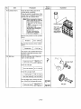
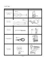
3.11.21 Tools
Name of tool
Shape
Governor weight support
extractor
721820-92580
Timer extractor
158591-54200
Spring set bar
121978-51610
Prestroke measuring device
155900-51350
Pressure gauge
155900-51500
- 3-43-24 -
Apprication