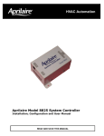
Download Aprilaire 8346 Product guide
Transcript
Aprilaire Zoned Comfort Control
Product Guide
Making Zoning As Easy As
w w w . a p r i l a i r e c o n t r a c t o r. c o m
Table of Contents
Why Choose Aprilaire?
(3)
• The Right Products
• Sales and Marketing Support
• Technical Support
An Overview of Aprilaire Zoned
Comfort Control
(4)
• What is a Zoned Comfort Control system?
• Why would a homeowner or light commercial
user need Zoned Comfort Control?
• What are the components of a Zoned
Comfort Control system?
• How does Zoned Comfort Control work?
• When is the best time for a Zoned Comfort
Control system to be installed?
• Why is pressure relief an issue with Zoned
Comfort Control systems?
• Zoning is the more profitable solution.
• The fact is that everyone benefits!
Designing an Aprilaire Zone
is as Easy as 1, 2, 3
(8)
• Selecting Zones
• Determine Bypass Method
• Selecting Zone System Components
Aprilaire Zone Comfort
Control Panels
• 6202 and 6203 Control Panels
• 6303 Control Panel
• 6404 Control Panel
• 6402 Expansion Panel
• 6504 Control Panel
2
The “Engineered Reliability”
of Aprilaire Zoned Comfort
Control Dampers
(17)
•
•
•
•
•
Rectangular Dampers
Round Dampers
Barometric Bypass Dampers
Static Pressure Bypass Dampers
Retrofit Damper
Aprilaire Thermostats
• 8570 Thermostat
• 8300 Series Thermostat
• 8200 Series Thermostat
• Thermostat Accessories
• 8051 Flush Mount Sensor
• 8052 Outdoor/Duct Sensor
• 8053 Surface Mount Sensor
• 8022 3-wire to 4-wire Adapter
• 8023 Thermostat Adapter Plate
• 8024 Universal Relay Pack
Aprilaire Zoned Comfort Control
Panel Wiring Diagrams
(28)
• Aprilaire
• Aprilaire
• Aprilaire
• Aprilaire
(11)
(23)
Model
Model
Model
Model
6202
6303
6404
6504
and 6203 Control Panels
Control Panel
Control Panel
Control Panel
Why Choose Aprilaire?
1) The Right Products
• Aprilaire® has the right controls for any job—whether you are looking for simple low-cost control panels ideal
for new construction, an expandable zone system for light commercial or the consumer benefits associated
with the Model 6504 Intelligent Zoned Comfort system, we have the right control for your application.
• The most reliable dampers available today—the exclusive Flexible Link™ design eliminates the components
most prone to failure… gears!
• Thermostats to complete the job—while most Aprilaire zone control systems are compatible with virtually any
manufacturers thermostats, an Aprilaire thermostat is the best choice for a complete Aprilaire Zoned Comfort
Control system.
• Warranty—Aprilaire products are warranted for five full years from installation, helping to protect your
quality reputation.
2) Sales and Marketing Support
• Aprilaire brand—well recognized and respected, the Aprilaire brand is synonymous with reliable, simple-tooperate Indoor Air Quality products.
• Free, high-quality sales literature—drawing on our many years of marketing Zoned Comfort Control to
consumers and light commercial users, we have developed a very compelling message for your customer that
will make selling zoning easier for you.
• Consumer website—our state-of-the-art website, www.aprilaire.com, is designed to guide the consumer into a
purchase decision. The effective problem/solution format helps support your selling message and close the sale!
3) Technical Support
• Local training—Aprilaire has local representation available for on-site training and support. Our district sales
manager is there for you.
• Unsurpassed technical support—a Zoned Comfort Control expert will be answering your call! The Aprilaire
team of technical support representatives takes pride in its mission to handle your issue with ONE call.
• Additional support—In addition to our highly trained experts answering your phone calls, we have a contractor
only website designed to provide you with the technical documents you need, from installation manuals to
technical bulletins. Aprilaire support is there for you 24/7 at www.aprilairecontractor.com.
3
An Overview of
Aprilaire Zoned Comfort Control
Zoning delivers
better comfort control
for various types
of floor plans
What is a Zoned Comfort Control system?
Zoned Comfort Control is the practice of dividing a home or building into separate areas
or ‘zones’ to be independently heated or cooled based upon the demand in each zone.
Multiple levels
Typically the term refers to a single piece of equipment controlled by two or more
Bonus room
thermostats.
Some may use the term ‘zoned’ when referring to the installation of
multiple heating or cooling systems. However, the classic use of the term implies that a
single heating and cooling system is divided, by means of its ductwork, to serve multiple
zones each with their own individual thermostat control. Further, zone dampers are
located in the ductwork to direct the conditioned air to where it’s needed, when it’s
needed. A control panel coordinates the operation of the equipment with the distribution
Expansive
glass
area
of the conditioned air.
Why would a homeowner or light commercial user need
Zoned Comfort Control?
Finished basement
It is nearly impossible to maintain comfort throughout a home or building from one
thermostat. The thermostat only measures the temperature where it is located; therefore,
you may be very comfortable near the thermostat while areas further away or directly
above or below will not be comfortable. Virtually every structure has varying
requirements depending upon the room or area. For example, because heat rises, rooms
on the upper levels will always be warmer than on the first floor. Other examples that
Atrium
produce the need for Zoned Comfort Control are:
Exposure: expansive south-facing glass will soak up the sun during the day and lose
more heat at night
Construction: rooms built over an unconditioned space or built over a slab have
different heating/cooling requirements than areas over conditioned spaces
Occupancy: the ability to set back the thermostat setting in unoccupied areas
saves energy
4
APRILAIRE ZONED COMFORT CONTROL PRODUCT GUIDE
What are the components of a Zoned
Comfort Control system?
The system is comprised of virtually any forced air HVAC
equipment, a control panel, dampers (usually one for each
zone, however, multiple dampers may be used),
thermostats (one for each zone) and the ductwork. In
addition, depending upon the system’s design, a bypass
damper may be required for pressure relief.
How does Zoned Comfort Control work?
Thermostats in each zone are wired to the Zoned Comfort Control panel. The control panel is then wired to
the HVAC equipment and to zone dampers located in the system’s ductwork. The control panel understands
each zone’s need for conditioning and operates the equipment (on/off) while controlling the position of the
dampers (open/closed) based upon the thermostat requirements. This assures that conditioned air is
directed where and when it’s needed.
When is the best time for a Zoned Comfort Control system to be installed?
It is least expensive and easiest to install in a new home. However, in most cases, Zoned Comfort Control
can be added to existing systems at any time. Retrofit applications can pose challenges, but Aprilaire®
addresses these challenges with a special retrofit damper designed to be low in cost and easy to install in
existing systems.
OverviewOverview
of Zonedof
Comfort
Zoned Control
ComfortSystems
Control
Why is pressure relief an issue with Zoned Comfort Control systems?
It is important to design zone systems to account for the added system pressure that is caused when zone
dampers are closed. With Zoned Comfort Control, as dampers close to restrict airflow to non-calling areas,
the equipment will attempt to deliver its full capacity, although only a percentage of airflow is required.
Therefore, to avoid problems that are associated with restricting the airflow, (i.e., high limit, freezing of the
coil, air noise) some method of pressure relief is required. This may include over-sizing of the ductwork (all
zones capable of carrying 70% of the system’s airflow), using a bypass damper, or Aprilaire’s exclusive
‘Controlled Pressure Relief (CPR)’ method. The CPR method involves slightly over-sizing the system’s supply
ductwork while an engineered amount of bypass is allowed into a closed zone. This method eliminates the
need for a bypass damper, minimizing system cost while maximizing comfort. (For more information on
designing for pressure relief, see the Aprilaire Design Manual, Form #5001.)
G o t o w w w . a p r i l a i r e c o n t r a c t o r. c o m t o o r d e r l i t e r a t u r e o r d o w n l o a d p r o d u c t d o c u m e n t a t i o n .
5
Zoning is the more profitable solution.
Just like all good businesses, HVAC contractors are always looking for an “edge” over
their competition. Whether you are attempting to maintain your profitability against
stiffened competition in a tightening new construction market or looking for creative
ways to secure new business, Zoned Comfort Control is the answer.
Zoned Comfort Control has been around for many years. Even before zone dampers and
controls, HVAC contractors provided “zoned” heating and cooling by installing multiple
systems to generate a greater level of comfort and energy-savings for homeowners.
However, the economics of the multi-system approach prove inferior and have grown
worse with the new federal mandate for 13 SEER equipment.
Not everyone has embraced or fully understands the benefits of Zoned Comfort Control.
Perhaps they are simply under the impression that they are making more profit by selling
two systems. However, the reality is that you can accomplish improved comfort and
energy savings through installing Zone Comfort Control at a lower cost, with greater
profit, than installing two separate systems. In addition, you will provide the consumer
with an HVAC system that costs less to maintain. Here is an example:
Two 2 1/2 Ton Systems
Equipment
6" Branch
Ductwork*
Dampers
Zone Control
Panel
Wire,
Transformer,
etc
Labor
Total
One 5 Ton System, Zoned
Cost/Unit
System
Cost
Cost/Unit
System
Cost
(2) Furnaces
(1000 CFM each)
Two 2.5 Ton AC unit
$798
$1,596
2000 CFM Furnace
$1,034
$1,034
$711
(2) Evap Coils
(std Orifice/cap tube)
(2) Line Sets
$222
$1,422
5 Ton AC unit
$1,248
$1,248
$444
(1) Evap Coils
(std Orifice/cap tube)
(1) Line Set
$366
$366
$50
$100
(4) Mounting Pads
(Furnace & Cond
Unit)
(2) Gas Lines
$20
$50
$50
$80
(2) Mounting Pads
(Furnace & Cond Unit)
$20
$40
(2) Sets of Vent Pipes
$300
$600
(1) Gas Line
$300
$300
$350
$700
(1) Set of Vent Pipes
$350
$350
(2) Humidifiers
$350
$700
(1) Humidifier
$350
$350
(2) Air Cleaner
$250
$500
(1) Air Cleaner
$250
$250
20 (10' Each)
$150
$3,000
24 (10' Each)
$150
$3,600
NA
Two - 14" Round Dampers
$110
$220
NA
Zone Control Panel
$95
$95
NA
Transformer
$50
$50
$1,120
(24) Hours
$35
$840
(32) Hours
$35
$10,262
$8,793
Zoning difference vs. two systems
A savings of more than
$1,469
14%
*Cost of ductwork not noted is equivalent in both systems.
additional branches which are accounted for.
6
APRILAIRE ZONED COMFORT CONTROL PRODUCT GUIDE
Zoning may require
As you can see from our example, the contractor cost is $1,469 less when offering Aprilaire® zoning versus two
systems. Additionally, there are many other important factors to consider aside from the equipment cost alone.
For example:
– Two systems require six slots in electrical panel to be taken (2x for each A/C unit and 1x for the
furnace) versus three slots for a zoned system.
– Incidentals such as a condensate pump (where applicable) for each system must also be taken into
account.
– There are numerous space issues with having to place two furnaces, two sets of vent piping, two
condensers (which are now larger) etc.
– Most often a house has limited space for intakes/exhausts due to a garage taking one side, the front
side being undesirable for equipment, and the rear usually being partially taken up by a patio, leaving
only one side and possibly some rear area for equipment. Code dictates placement in many cases:
– Fresh air intake must be ten feet away from any exhaust or gas/electrical service
– Exhaust vent must be four feet from the gas regulator
– Intake vent must be one foot lower than exhaust
– Exhaust vent must be one foot from windows
The fact is that everyone benefits!
How the home owner wins:
• True zoned comfort
• Lower maintenance costs
• Potential for added Indoor Air Quality benefits
• Energy savings versus a single non-zoned system
Overview of Zoned Comfort Control Systems
How the contractor wins:
• Win more bids
• Make more profit
• Happy builders
How the builder wins:
• Satisfied homeowners
• Potential cost control versus 13 SEER mandate
• Less time needed by contractor in the home
Today’s homes need Zoned Comfort Control and zoning has many advantages over multiple systems.
Contact your local Aprilaire representative to discuss how you can benefit.
G o t o w w w . a p r i l a i r e c o n t r a c t o r. c o m t o o r d e r l i t e r a t u r e o r d o w n l o a d p r o d u c t d o c u m e n t a t i o n .
7
Designing An
Aprilaire Zone
Is As Easy As
HVAC SYSTEM
SIZING
WHEN ZONING
Designing a system to
incorporate zoning is
really no different than
designing a non-zoned
system. You still need to
size for peak demand
based upon a good
Manual ‘J’ calculation
and you still need to
Designing the Zone System
understand how much
Refer to the Aprilaire® Zoned Comfort Control Design Guide (Form #5001) for complete and
detailed information regarding system design. Here are the basic 1-2-3 steps.
air is to be delivered to
each room, again based
upon Manual ‘J’.
Selecting Zones
The first thing that is required after you have determined what type and size forced
air heating and cooling equipment you will be using is determining which rooms will
make up the various zones for your system. Considerations include:
a) Occupancy: group rooms based upon their common occupancy patterns (i.e.,
bedrooms together or living, dining and kitchen together).
b) Exposure/Construction: group rooms that have similar load patterns (i.e., first
floor versus second floor, south facing versus north facing).
c) Size: ideally, each zone should be approximately equal in size. Having smaller
zones could potentially increase velocity and air noise.
Some additional thoughts:
• The more open the floor plan, the less ability you will have to “contain” the temperatures (air) within zones. Establish your customer’s expectations up front.
CONVENIENT DESIGN
TOOL AVAILABLE FORM #5018
• More is not always better. In the case of zoning, there are significant tradeoffs
when determining zones. Some customers may believe that “more is better,”
which can create unequal, and in some cases, very small zones. Resist the
temptation of selling as many zones as possible since you may never realize the
additional profits due to persistent call-backs. Refer to ‘c’ above.
8
APRILAIRE ZONED COMFORT CONTROL PRODUCT GUIDE
Determine Bypass Method
• Controlled Pressure Relief method: the unique Aprilaire® method of zoning that doesn’t require a
bypass damper and, therefore, minimizes system costs. The Controlled Pressure Relief method
assures a minimum of 85% of design airflow across the evaporative coil at all times, while not affecting
the temperature of non-calling zones by more than 1°F, assuring system performance and comfort.
By following our engineered design methods, which include slightly over-sizing the duct system and
utilizing Aprilaire factory-preset dampers, we relieve pressure into non-calling zones without affecting
the temperature (see Form #5001 for design details).
Controlled Pressure Relief is perfect for
residential new construction applications.
Positives: assures proper airflow; simplifies installation; lowers system costs.
Negatives: may not be applicable to existing systems; each zone must represent at least 25% of total
system airflow.
• Bypass Damper method: allows the system designer to size the ductwork in the same manner as
a non-zoned application. The pressure relief is handled by use of a bypass damper directing
excess airflow back to the return or to a dump zone.
Determine bypass damper sizing: the purpose of the bypass damper is to maintain airflow
through the HVAC equipment when zone dampers close. Sizing the bypass damper is calculated
considering worst case scenario. Subtract the air flow of the smallest zone from the total system
airflow and the difference is how much air you need to bypass. (Total system CFM - Smallest
zone CFM = Amount of air to bypass). Then, refer to the bypass damper sizing chart for the right
size bypass damper.
Positives: utilizes existing duct design methods; good retrofit option.
Negatives: potential of bypassed air conditioning the return or dump zone; requires plenum
temperature control (included with Aprilaire zone panels).
Overview of Zoned Comfort Control Systems
• Oversize method: entails sizing the ductwork (main and branches) in each zone to accommodate
approximately 70% of the total system airflow.
Positives: no bypass damper is needed; low likelihood of air noise.
Negatives: cost (duct materials); requires additional space; can result in lack of velocity or “throw”
from the registers.
Selecting Zone System Components
The following pages will assist you with selecting the right components for the job.
• Select control panel based upon:
–Type of equipment to be controlled (heat/cool or heat pump, single- or multi-stage)
–Number of zones to be controlled
–Additional feature needs (i.e., customer would like the ability to change thermostat
settings from any thermostat, in which case you would choose the Model 6504)
• Select the correct type and size dampers for the job
• Select the correct thermostats
G o t o w w w . a p r i l a i r e c o n t r a c t o r. c o m t o o r d e r l i t e r a t u r e o r d o w n l o a d p r o d u c t d o c u m e n t a t i o n .
9
Aprilaire Zone Comfort Control Panels
Step One: Select A Zoned Comfort Control Panel
There are three important questions that need to be answered before choosing a control panel:
1
What type of equipment do you want to control? This refers to whether you want to control a
conventional heat/cool system such as a split system furnace and air conditioner or a heat pump.
Aprilaire® works with all types of forced-air systems including gas or electric furnaces, air-to-air or
water source heat pump, as well as combination systems such as dual fuel set-ups.
2
Is the equipment single-stage or multi-stage? While single-stage is fairly straightforward, multi-stage
equipment may offer choices for the control panel. For example, you may choose to have multi-stage
equipment upstage based on timers or other controls internal to the piece of equipment. If so, use a
single-stage control panel. However, if you are looking for the control panel or the thermostats to
provide staging of the equipment, then a multi-stage control panel is required.
3
How many zones will you be controlling? This is determined by your evaluation of the home or
building as well as the desires of the user. Once determined, select the control panel that fits the
design. In some applications it may be worth considering a panel that provides an extra zone in case
a new zone is added later. For example, if the customer is considering finishing a basement or attic
space at a later date, this extra zone will be available.
Conventional Heat / Cool
1
2
3
Model 6202
Model 6203
Model 6303
Model 6404
Model 6504
Single-Stage
2
3
•
•
•
•
•
•
•
4
•
•
Heat Pump
Multi-Stage
4-12
•
2
•
•
3
•
•
4
•
•
Single-Stage
Multi-Stage
4-12
2
3
4
4-12
2
3
4
4-12
•
•
•
•
•
•
•
•
•
•
•
•
•
•
•
•
•
The next step in the control panel selection process is to determine whether any additional control features
are desired. The following pages describe the additional features offered with the Aprilaire Zoned Comfort
Control system. Take some time to read over what each has to offer prior to sitting down with your
prospective customers.
Control Panels
G o t o w w w . a p r i l a i r e c o n t r a c t o r. c o m t o o r d e r l i t e r a t u r e o r d o w n l o a d p r o d u c t d o c u m e n t a t i o n .
11
Step One: Select A Zoned Comfort Control Panel
6202 and 6203 Control Panels
SIMPLE, COST-EFFECTIVE ZONED COMFORT CONTROL
The 6200 Series control panels are designed for single-stage heat/cool
systems only. The simple and straight-forward installation prevents
time wasted on complicated set-up steps that could create a callback.
The simplicity and low cost make the 6200 Series control panels
perfect for new construction applications or as an add-on for an
existing home.
The Model 6202 is for two-zone applications and the Model 6203 can be used for two- or threezone systems. Each has all the basic features required for a solid performing zoned comfort system.
THERMOSTAT REQUIREMENTS
ZONE
TYPE
All Zones
Single-Stage
Heat/Cool
TERMINALS REQUIRED *
RECOMMENDED THERMOSTATS
R (24V-hot)
W (Heat)
Y (Cool)
G (Fan)
Programmable
• Aprilaire Model 8363
• Aprilaire Model 8570
Non-Programmable
• Aprilaire Model 8344
*An available “C” terminal (24-volt common) in each zone of the control panel can be used for 24-volt powered thermostats.
Models 6202 and 6203
CONSUMER BENEFITS
CONTRACTOR BENEFITS
ANY ZONE SETS MODE
• Provides true independent control for each zone.
PLENUM TEMPERATURE CONTROL (ADJUSTABLE)
• Protects equipment from excessive high and low temperatures
caused by reduced airflow when small zones are calling.
CONTINUOUS FAN BY ZONE
• Individual zone thermostats can call for fan operation by zone.
ZONE CHANGEOVER BASED ON TIME
• If calls for opposite modes exist, the control panel will alternate to
satisfy each call.
6202 and 6203 Control Panels
FAN PURGE
• Assures air is directed to last zone(s) calling.
SHORT CYCLE PROTECTION
• Protects the HVAC equipment from too frequent cycling.
MAINTENANCE FREE
• No maintenance or adjustments needed after installation.
L.E.D. STATUS INDICATORS
• Simplifies start up and troubleshooting for the contractor.
TIME DELAY OVERRIDE
• Speeds checkout for the installer.
WORKS WITH TWO OR THREE WIRE DAMPERS
• Compatibility if you are changing out an old panel with
three wire dampers.
FUSE PROTECTION
• Protects the control panel against mis-wiring.
EXTRA FUSE ON BOARD
• Convenience if fuse blows.
ADJUSTABLE PURGE TIMING
• Compatibility with all brands of equipment.
ELECTRIC / NON-ELECTRIC SWITCH
• Proper control of the fan (G-terminal) for either electric
or fossil fuel furnaces.
12
G o t o w w w . a p r i l a i r e c o n t r a c t o r. c o m t o o r d e r l i t e r a t u r e o r d o w n l o a d p r o d u c t d o c u m e n t a t i o n .
6303 Control Panel
Step One: Select A Zoned Comfort Control Panel
THE EASIEST HEAT PUMP CONTROL AVAILABLE
The Model 6303 control panel is designed for single-stage compressor,
heat pump systems only. A single-stage heat/cool (four wire) thermostat
can be used in each zone for the most economical installation solution;
however, a heat pump thermostat can be used in zone one for living space
control of the emergency heat mode. When heat/cool thermostats are used in all zones,
emergency heat is set at the control panel via a convenient switch. Auxiliary heat is controlled by a
fixed timer set for 20 minutes to assure homeowner comfort without expensive heat pump thermostats. The
simplicity and low cost of the Model 6303 make it perfect for new construction applications or existing homes.
THERMOSTAT REQUIREMENTS
ZONE
Zones 1–3
TYPE
Single-Stage Heat/Cool
TERMINALS REQUIRED *
RECOMMENDED THERMOSTATS
R (24V-hot)
W (Heat)
Y (Cool)
G (Fan)
Programmable
• Aprilaire Model 8363
• Aprilaire Model 8570
Non-Programmable
• Aprilaire Model 8344
Zone 1 Only
(Provides control of Emergency
Heat from Thermostat)
Single-Stage Heat Pump
R (24V-hot)
O (Reversing Valve-Cool)
W (Auxiliary Heat)
Y (Compressor)
G (Fan)
Programmable
• Aprilaire Model 8365
• Aprilaire Model 8570
Non-Programmable
• Aprilaire Model 8346
*An available “C” terminal (24-volt common) in each zone of the control panel can be used for 24-volt powered thermostats.
Model 6303
CONSUMER BENEFITS
CONTRACTOR BENEFITS
ANY ZONE SETS MODE
• Provides true independent control for each zone.
PLENUM TEMPERATURE CONTROL (ADJUSTABLE)
• Protects equipment from excessive high and low temperatures
caused by reduced airflow when small zones are calling.
CONTINUOUS FAN BY ZONE
• Individual zone thermostats can call for fan operation by zone.
ZONE CHANGEOVER BASED ON TIME
• If calls for opposite modes exist, the control panel will alternate to
satisfy each call.
FAN PURGE
• Assures air is directed to last zone(s) calling.
MAINTENANCE FREE
• No maintenance or adjustments needed after installation.
L.E.D. STATUS INDICATORS
• Simplifies start up and troubleshooting for the contractor.
TIME DELAY OVERRIDE
• Speeds checkout for the installer.
WORKS WITH TWO OR THREE WIRE DAMPERS
• Compatibility if you are changing out an old panel with
three wire dampers.
6303 Control Panel
SHORT CYCLE PROTECTION
• Protects the HVAC equipment from too frequent cycling.
THERMOSTAT FLEXIBILITY
• Use any four wire heat/cool thermostat in each zone or a heat
pump thermostat in zone one.
ADJUSTABLE PURGE TIMING
• Compatibility with all brands of equipment.
ELECTRIC / NON-ELECTRIC SWITCH
• Proper control of the fan (G-terminal) for either electric
or fossil fuel furnaces.
G o t o w w w . a p r i l a i r e c o n t r a c t o r. c o m t o o r d e r l i t e r a t u r e o r d o w n l o a d p r o d u c t d o c u m e n t a t i o n .
13
Step One: Select A Zoned Comfort Control Panel
6404 Control Panel
THE “ONE” CONTROL PANEL THAT DOES IT ALL
The Model 6404 control panel is the “One” control panel for
any type of zoning application from two to twelve zones. It
can be configured for single- or multi-stage, heat/cool or
heat pump and it’s perfect for residential or light
commercial applications. Simple, four wire thermostats
can be used in all zones. The multiple staging options
offered with the Model 6404 provide you the flexibility to
customize the system around the equipment being
controlled and the desires of your customers. You can
choose from timed-staging (adjustable), set up the
system to stage based upon the number of zones calling, or even use multistage thermostats for the most precise control.
The Model 6402 expansion panel is used with the Model 6404 control panel
to expand from four to twelve zones in two zone increments.
Model 6404 (and 6402)
CONSUMER BENEFITS
CONTRACTOR BENEFITS
ANY ZONE SETS MODE
• Provides true independent control for each zone.
PLENUM TEMPERATURE CONTROL (ADJUSTABLE)
• Protects equipment from excessive high and low temperatures
caused by reduced airflow or bypassing to the return.
CONTINUOUS FAN BY ZONE
• Individual zone thermostats can call for fan operation.
VACATION OPERATION
• Allows system to operate in setback from the thermostat
designated zone one when leaving for extended periods.
ZONE CHANGEOVER BASED ON TIME
• If calls for opposite modes exist, the control panel will alternate to
satisfy each call.
L.E.D. STATUS INDICATORS
• Visible through the cover, the L.E.D.’s allow your customer to aid in
troubleshooting.
FAN PURGE
• Assures air is directed to last zone(s) calling.
SHORT CYCLE PROTECTION
• Protects the HVAC equipment from too frequent cycling.
6404 Control Panel
MAINTENANCE FREE
• No maintenance or adjustments needed after installation.
THERMOSTAT FLEXIBILITY
• Use single- or multi-stage heat/cool or heat pump thermostats
depending on the application. Simple four wire heat/cool
thermostats can control any type of equipment.
L.E.D. STATUS INDICATORS (VISIBLE THROUGH COVER)
• Simplifies start up and troubleshooting.
SELECTABLE STAGING OPTIONS
• Stage by time, thermostat input or number of zones calling.
TIME DELAY OVERRIDE
• Speeds checkout for the installer.
WORKS WITH TWO OR THREE WIRE DAMPERS
• Compatibility if you are changing out an old panel with three wire dampers.
ADJUSTABLE PURGE TIMING
• Compatibility with all brands of equipment.
ACCESSORY TERMINALS
• Auxiliary output relays available to control humidifiers, electronic
air cleaners or other accessories tied to heat or blower operation.
DUAL FUEL OPERATION
• Control of heat pumps with fossil fuel auxiliary heat.
MODEL 6402 ZONE EXPANSION PANEL
• L.E.D. indicators simplify start-up and troubleshooting.
• Fuse protected.
• Easy wire 45° angled terminals.
SINGLE CONTROL FOR ALL EQUIPMENT TYPES
• Operates single- or multi-stage heat/cool or heat pump systems up
to twelve zones.
14
G o t o w w w . a p r i l a i r e c o n t r a c t o r. c o m t o o r d e r l i t e r a t u r e o r d o w n l o a d p r o d u c t d o c u m e n t a t i o n .
6504 Control Panel
Step One: Select A Zoned Comfort Control Panel
THE ULTIMATE IN COMFORT, CONVENIENCE, AND CONTROL
The Model 6504 is the control panel to choose when your
customers demand the best. It controls all types of HVAC
equipment and provides state-of-the-art features found in no
other control panel offered today.
The system utilizes a Model 8570 premium thermostat in each
zone with a simple, four wire connection to the zone panel,
regardless of the HVAC equipment type (heat/cool, heat pump,
single- or multi-stage). Connection is also provided for an
Aprilaire® automatic humidifier control to share the homes
relative humidity (RH) level and the outdoor temperature with
each thermostat and optimize humidity control. The simple,
menu-driven operation of the Model 8570 provides: easy operation; the
ability to control any zone from any other; and the ability to view RH at each thermostat–
providing user convenience. The built-in ventilation control helps assure a healthful and comfortable home
environment. Simply intelligent!
Model 6504
CONSUMER BENEFITS
CONTRACTOR BENEFITS
UNPARALLELED COMFORT AND CONVENIENCE
• Control temperature based upon the need in each zone.
• “Global changes”—allows changes to any one zone or all zones
from any thermostat in the system.
• Enhanced humidifier performance through extending blower run
time. Each thermostat even displays when the Aprilaire humidifier
is operating.
• View outdoor temperature and indoor relative humidity on every
thermostat. (Aprilaire automatic humidifier control required for
RH display.)
• Maintenance reminders for air filter, humidifier, UV lamp, and HVAC
service assure peak performance and save the homeowner
time by displaying contractor contact information.
SIMPLIFIES SYSTEM SELLING PROCESS
• Makes it possible to present your customer with one buying
decision—a complete Aprilaire Indoor Air Quality system.
• Provides even more value than individual Aprilaire products
through enhanced system capabilities.
SIMPLEST OPERATION
• The Model 8570 thermostat features menu-driven programming for
easy operation–even without a manual.
6504 Control Panel
ASSURES PROPER VENTILATION
• Built-in ventilation control allows the home to “breathe”properly
when equipped with a fresh air damper.
• Won’t bring in outside air that is too hot or cold.
SIMPLE INSTALLATION
• Thermostat wiring is easy. A simple, four wire connection is all
that’s required regardless of system type or accessories used.
• Loaded with self diagnostic features that make installation and
checkout quick and effortless.
• Automatic thermostat recognition with L.E.D. indication.
• System test button and L.E.D. indicators automatically sequence
through all the control outputs to assure operation.
• The system will automatically send a message to the thermostat
display if any set-up options don't coincide between the thermostat
and control panel.
DUAL FUEL OPERATION
• Control of heat pumps with fossil fuel auxiliary heat.
G o t o w w w . a p r i l a i r e c o n t r a c t o r. c o m t o o r d e r l i t e r a t u r e o r d o w n l o a d p r o d u c t d o c u m e n t a t i o n .
15
Step Two: Select Zoned Comfort Control Dampers
The “Engineered Reliability” of Aprilaire
Zoned Comfort Control Dampers
Aprilaire® residential dampers feature a technological breakthrough in damper design. The Flexible Link™
design used in Aprilaire dampers eliminates the component most prone to failure in competitor’s residential
dampers… GEARS! The simple, yet ultra-reliable design is illustrated below. As the damper motor rotates the
SPOOL, the Flexible Link shortens and the spring-loaded LEVER ARM rotates the blade. When power to the
motor turns off, the spring quietly returns the blade to the open, “Fail-Safe” position. It’s really that simple.
Dampers
G o t o w w w . a p r i l a i r e c o n t r a c t o r. c o m t o o r d e r l i t e r a t u r e o r d o w n l o a d p r o d u c t d o c u m e n t a t i o n .
17
Rectangular Dampers
Step Two: Select Zoned Comfort Control Dampers
Aprilaire® offers all the rectangular sizes you need for residential and
light commercial applications. Residential sizes feature the exclusive
Flexible Link™ design while the larger, light commercial sizes (shaded
blue in the table) utilize actuators matched to the needed torque
requirements from a well-respected commercial actuator supplier.
REPLACEMENT PARTS
Model 6992 - Motor (gear shaft) for older Aprilaire and PerfectTemp™ dampers.
(Identified by metal actuator cover.)
Model 6993 - Motor (shaft with two flat sides) for all Flexible Link style Aprilaire
dampers. (Identified by plastic actuator cover.)
Model 6997 - Direct couple motor. (Identified as shaded, light commercial dampers
in chart.)
Rectangular Dampers
Size & Stock No.
Side
Mount
Nominal Height
(Motor on
short side)
Bottom
Mount
Rectangular Dampers
(Motor on
long side)
Nominal Width
8"
10"
12"
14"
16"
18"
20"
22"
24"
26"
28"
30"
(200mm) (250mm) (300mm) (350mm) (400mm) (450mm) (500mm) (550mm) (600mm) (650mm) (700mm) (750mm)
8" (200mm)
6721
6722
6723
6724
6725
6726
6727
6728
6729
6730
6731
6753
10" (250 mm)
—
6732
6733
6734
6735
6736
6737
6738
6739
6740
6741
6742
12" (300 mm)
—
—
6743
6744
6745
6746
6747
6748
6749
6750
6751
6752
14" (350 mm)
—
—
—
6754
6755
6756
6757
6758
6759
6760
6761
6762
16" (400 mm)
—
—
—
—
6763
6764
6765
6766
6767
6768
6769
6770
18" (450 mm)
—
—
—
—
—
6771
6772
6773
6774
6775
6776
6777
20" (500 mm)
—
—
—
—
—
—
6778
6779
6780
6781
6782
6783
22" (550 mm)
—
—
—
—
—
—
—
6784
6785
6786
6787
6788
24" (600 mm)
—
—
—
—
—
—
—
—
6789
6790
6791
6792
26" (650 mm)
—
—
—
—
—
—
—
—
—
6793
6794
6795
28" (700 mm)
—
—
—
—
—
—
—
—
—
—
6796
6797
30" (750 mm)
—
—
—
—
—
—
—
—
—
—
—
6798
8" (200 mm)
6721
6812
6813
6814
6815
6816
6817
6818
6819
—
—
—
10" (250 mm)
—
6732
6823
6824
6825
6826
6827
6828
6829
—
—
—
12" (300 mm)
—
—
6743
6734
6835
6836
6837
6838
6839
—
—
—
RESIDENTIAL FEATURES
LIGHT COMMERCIAL FEATURES (SHADED)
•
POWER-CLOSE/SPRING-OPEN OPERATION
•
DIRECT COUPLED, POWER-CLOSE/SPRING-OPEN
•
TWO WIRE INSTALLATION
•
TWO WIRE INSTALLATION
•
24VAC, 6W, 10VA
•
24VAC, 5W, 7VA
•
60HZ SYNCHRONOUS TYPE MOTOR
•
NEMA 2 ENCLOSURE
•
IMPEDANCE PROTECTED FOR CONTINUOUS STALL
•
ADJUSTABLE STOP
•
ADJUSTABLE STOP
•
35 IN./LB. TORQUE
•
INSTALLS IN 4.25 INCH SLOT IN DUCT
•
INSTALLS IN 5.25 INCH SLOT IN DUCT
NOTE: ACTUAL HEIGHT & WIDTH ARE UNDERCUT 0.25 INCH
NOTE: ACTUAL HEIGHT IS UNDERCUT 0.1875 INCH
ACTUAL WIDTH IS UNDERCUT 0.125 INCH
18
G o t o w w w . a p r i l a i r e c o n t r a c t o r. c o m t o o r d e r l i t e r a t u r e o r d o w n l o a d p r o d u c t d o c u m e n t a t i o n .
Round Dampers
Aprilaire® round dampers come in all the sizes you
Step Two: Select Zoned Comfort Control Dampers
need and work well with either rigid metal or flex duct.
Adjustable blade positioning and an integrated foam
seal provide flexibility for any type of zone job.
REPLACEMENT PARTS
Model 6992 - Motor (gear shaft) for 18" and 20" round dampers and older Aprilaire
and PerfectTemp™ round dampers. (Identified by metal actuator cover.)
Model 6993 - Motor (shaft with two flat sides) for all Flexible Link™ style Aprilaire
round dampers. (Identified by plastic actuator cover.)
Round Dampers
Size & Stock No.
Nominal Diameter
6"
8”
10"
12"
14"
16"
18"
20"
(153mm) (200mm) (250mm) (300mm) (350mm) (400mm) (450mm) (500mm)
Zone (normally-open / power-close)
6606
6608
6610
6612
6614
6616
6618
6620
Ventilation (normally-closed / power-open)
6506
6508
—
—
—
—
—
—
6600 Series
SPECIFICATIONS
•
POWER-CLOSE/SPRING-OPEN OPERATION
•
TWO WIRE INSTALLATION
•
24VAC, 6W, 10VA
•
60HZ SYNCHRONOUS TYPE MOTOR
•
IMPEDANCE PROTECTED FOR CONTINUOUS STALL
•
ADJUSTABLE STOP (IN CLOSED POSITION)
6500 Series
SPECIFICATIONS
POWER-OPEN/SPRING-CLOSE OPERATION
•
TWO WIRE INSTALLATION
•
24VAC, 6W, 10VA
•
60HZ SYNCHRONOUS TYPE MOTOR
•
IMPEDANCE PROTECTED FOR CONTINUOUS STALL
•
ADJUSTABLE STOP (IN OPEN POSITION)
Round Dampers
•
G o t o w w w . a p r i l a i r e c o n t r a c t o r. c o m t o o r d e r l i t e r a t u r e o r d o w n l o a d p r o d u c t d o c u m e n t a t i o n .
19
Barometric Bypass Dampers
Step Two: Select Zoned Comfort Control Dampers
Aprilaire® barometric dampers are simple to install and adjust. We
offer all the sizes you need to complete your zoning applications.
Round Dampers
Size & Stock No.
Nominal Diameter
8”
10"
12"
14"
16"
(200mm) (250mm) (300mm) (350mm) (400mm)
Barometric pressure relief (weight activated)
6908
6910
6912
6914
6916
PRODUCT FEATURES
•
LEFT OR RIGHT HAND MOUNTED WEIGHT ARM
•
INTEGRATED FOAM SEAL
•
HORIZONTAL OR UP FLOW ORIENTATION
•
CRIMPED END FOR EASY INSTALLATION
•
RIGID CONSTRUCTION HOLDS ITS SHAPE
Static Pressure Bypass Dampers
Static pressure controlled dampers provide a heightened
level of control for your zoning applications, and are
especially beneficial in large systems and those using
variable speed.
REPLACEMENT PARTS
Model 6994- Motor for static pressure dampers
Model 6995- Replacement pressure switch
Model 6996- Tube and probe kit
Round Dampers
Size & Stock No.
Static pressure relief (power activated)
Nominal Diameter
8”
10"
12"
14"
16"
18"
20"
(200mm) (250mm) (300mm) (350mm) (400mm) (450mm) (500mm)
6208
6210
6212
6214
6216
6218
6220
•
24 VOLT MODULATING ACTUATOR
•
SOLID STATE PRESSURE SENSOR
•
ADJUSTABLE PRESSURE RANGE - 0.17 TO 2 INCHES
•
PRESSURE ADJUSTMENT L.E.D.
•
INTEGRATED NEOPRENE SEAL
•
BLADE POSITION INDICATOR
Bypass Dampers
PRODUCT FEATURES
20
G o t o w w w . a p r i l a i r e c o n t r a c t o r. c o m t o o r d e r l i t e r a t u r e o r d o w n l o a d p r o d u c t d o c u m e n t a t i o n .
Retrofit Damper
Step Two: Select Zoned Comfort Control Dampers
Aprilaire® has broken open the service and replacement revenue
stream for zoned comfort control with the first-ever, spring-return
damper designed to be inserted in a six inch round branch duct.
Virtually every home without zoning has comfort problems. It is now
affordable to zone these homes without costly, and sometimes
impossible, duct modification.
By offering this simple solution, you provide your customers with
true comfort throughout their home, better than operating constant
fan or manually adjusting registers. You also assure your quality
reputation with enhanced customer satisfaction through increased
comfort and reliable, maintenance-free operation.
Model 6706
CONSUMER BENEFITS
CONTRACTOR BENEFITS
COMFORT
• The temperature where and when they want it.
PROFITABLE
• You can now provide an economical solution to your customer’s
comfort needs securing more sales.
CONVENIENCE
• System is completely automatic. Add programmable thermostats or
the Aprilaire Zoned Comfort Control system for the ultimate
convenience and control.
ENERGY SAVINGS
• It makes sense; don’t waste energy conditioning the whole home,
only condition areas that need it. “Would you have a single light
switch for you entire home?”
MODEL 6706 - DAMPER SPECIFICATIONS
DUCT SIZE
OVERALL SIZE
WEIGHT
POWER REQUIREMENT
RESISTANCE
6" round
3.3"(H)x 8.0"(W)x 8.3"(D)
1 lb.
10 VA @ 24 VAC
0.008" W.C. @ 700 fpm
EASY INSTALLATION
• Simply cut a slot, insert the damper, and screw or strap the damper
to the duct.
INSTALLER FRIENDLY
• High-resolution L.E.D. on the damper illuminates when closed,
simplifying check-out and troubleshooting.
RELIABLE
• “No gears” technology assures long life.
FAIL SAFE
• Spring-open operation assures airflow and minimizes
after-hour callbacks.
Model 8028 Power Distribution Panel
• Simplifies installation when the number of dampers exceeds
the fuse rating of the control panel
6706 Retrofit Damper
• Makes troubleshooting easier
• Gives a professional and clean appearance to your installation
MODEL 8028 - POWER DISTRIBUTION PANEL SPECIFICATIONS
MAX. DAMPER POWER INPUT PER ZONE
DAMPER FUSE SIZE
CONTROL INPUT CURRENT DRAW (ZONE A & B)
MAX. NO. OF APRILAIRE DAMPERS PER ZONE
MAX. WIRE SIZE
APPLICATION TEMPERATURE / RH
100 VA @ 24 VAC
5 A fast acting (spare supplied)
50 mA @ 24 VAC
10
18 AWG
140˚F / 90% RH (non-condensing)
G o t o w w w . a p r i l a i r e c o n t r a c t o r. c o m t o o r d e r l i t e r a t u r e o r d o w n l o a d p r o d u c t d o c u m e n t a t i o n .
21
Aprilaire Thermostats
Step Three: Select A Thermostat
Aprilaire® has a complete line of thermostats for all your applications, including those that utilize Zoned
Comfort Control.
The process of selecting the correct thermostat for the application is largely the same for both single
thermostats and zoning applications:
1. Determine if the application calls for a programmable or a non-programmable thermostat.
2. Determine what type of equipment you need to control and/or the requirements of the zone control
panel you will be using.
3. Understand the features and capabilities that your customers need.
A good way to look at the selection process is by using a Good-Better-Best approach.
Best:
The Model 8570 is truly the all-in-one thermostat for all
types of applications. This model is field configurable for
programmable or non-programmable operation and controls
all types of heating and cooling equipment. It also offers a full
array of advanced features to satisfy the needs of any of your
customers.
Better: The 8300 Series has models available to suit your
applications and are battery powered, so no extra wires are
needed when changing out older thermostats. Advanced
features such as air filter and water panel service monitors,
adjustable calibration, and simplified programming make it a
great choice for zoning or stand-alone applications.
Electronic Thermostats
Good: The 8200 Series provides good, basic control at an
affordable price. This series is hardwired and requires a
common connection (“C” terminal) so it is perfect for new
construction or zoning applications where you can run the
needed wires.
All Aprilaire zone control panels provide a
common connection (“C” terminal) for each zone thermostat.
G o t o w w w . a p r i l a i r e c o n t r a c t o r. c o m t o o r d e r l i t e r a t u r e o r d o w n l o a d p r o d u c t d o c u m e n t a t i o n .
23
Step Three: Select A Thermostat
8570 Thermostat
THE “ONE” THERMOSTAT
Whether the application is heat/cool or heat pump, singleor multi-stage, residential or light commercial, the Model
8570 is the thermostat to help build your business.
The Model 8570 thermostat provides exceptional value
for you and your customers because it is easy to install,
program, and operate.
Boasting a large, easy-to-read, vibrantly backlit display,
this thermostat provides more “at-a-glance” information
about the HVAC system, its accessories, and the indoor
and outdoor environment than any other thermostat.
Plus, its menu-driven operation is so intuitive, both you and your customers will find it simple to
program—even without the manual. It’s that easy. No more nuisance callbacks.
Model 8570
CONSUMER BENEFITS
CONTRACTOR BENEFITS
SIMPLEST PROGRAMMING AND OPERATION AVAILABLE
• Menu-driven approach results in the ultimate simplicity.
THE “ONE” THERMOSTAT FOR YOUR BUSINESS
• Ideal for both residential and light commercial applications.
• Controls either single- or multi-stage equipment.
• Compatible with virtually all types of equipment – split system,
rooftop, hydronic, heat pumps (including dual fuel), etc.
• Selectable operation: programmable or non-programmable.
LARGE BACKLIT DISPLAY
• Convenient viewing at any light level.
EQUIPMENT MONITORS
• Informs the user when to change their air filter, service their
humidifier or service their HVAC equipment. This results in greater
comfort, maximum operating efficiency, long equipment life and a
satisfied customer.
DISPLAYS OUTDOOR TEMPERATURE AND INDOOR RELATIVE HUMIDITY
• By means of connection to optional outdoor sensor or automatic
humidifier control, the thermostat becomes your personal indoor
environment center.
HOLIDAY FEATURE
• Allows the thermostat’s program to be overridden until the date and
time you select–whether you’re away for hours, days or weeks.
8570 Thermostat
PROGRESSIVE RECOVERY (SELECTABLE)
• Assures that the heating or cooling equipment starts at the optimum
time to reach your chosen set point after an overnight set back.
CUSTOMER RETENTION
• Thermostat displays your name and phone number, assuring you
get the call for service and replacement parts like air filters and
humidifier water panels.
SIMPLEST PROGRAMMING AND OPERATION
• Reduces nuisance calls associated with old fashioned
programmable thermostats.
• Intelligent installation options.
• Create intelligent solutions through connection to an Aprilaire
automatic humidifier control or Model 6504 zone control panel.
• View or control other thermostats through the Model 6504.
• Extend blower operation for added humidification run time.
• Displays when the humidifier is operating.
• View outdoor temperature and indoor relative humidity.
PERMANENT PROGRAM MEMORY
• The program and all application settings are permanently stored
even in the event of a power outage. Clock setting is maintained for
five days, accounting for routine equipment service.
AUTOMATIC DAYLIGHT SAVINGS TIME ADJUSTMENT (SELECTABLE)
24
G o t o w w w . a p r i l a i r e c o n t r a c t o r. c o m t o o r d e r l i t e r a t u r e o r d o w n l o a d p r o d u c t d o c u m e n t a t i o n .
8300 Series Thermostat
Step Three: Select A Thermostat
The 8300 Series thermostats provide exceptional value for
you and your customers because they are easy to install,
program and operate.
Programmable models are the easiest on the market—they
even tell you when programming is “DONE”.
Plus, they
are delivered complete with pre-programmed Energy Star
settings.
By offering and installing Aprilaire®—the most respected
premium brand in the HVAC industry for over 60 years—
you and your customers will enjoy maximum value, reliability, and easy operation, all of which have been
proven in extensive field testing.
The 8300 Series integrate easily with other Aprilaire products by informing your customers when to replace their
humidifier water panel and air filter, protecting your customer’s investments, and reminding them to call you.
Choose from these models to complete your quality installations:
Model 8344 – Non-Programmable, Single-Stage Heat/Cool
Model 8346 – Non-Programmable, Single-Stage Heat Pump w/Auxiliary Heat
Model 8348 – Non-Programmable, Multi-Stage Heat/Cool
Model 8363 – Programmable, Single-Stage Heat/Cool
Model 8365 – Programmable, Single-Stage Heat Pump w/Auxiliary Heat
Model 8368 – Programmable, Multi-Stage Heat/Cool
8300 Series
CONTRACTOR BENEFITS
LARGE BACKLIT DISPLAY
• Convenient viewing at any light level.
EASY INSTALLATION
• The unit is just the right size to cover existing thermostats.
• 45-degree angled terminals for easy wire termination.
• Can be mounted using the included drywall anchors or mounted to
a two by four inch junction box
• Recessed back plate accommodates wire routing.
• Battery powered with low battery indication (batteries included).
• No need to pull extra wires.
WATER PANEL CHANGE-INDICATOR ON THE DISPLAY
• Set it once at installation to remind homeowner when to contact
you for replacement water panels.
FILTER CHANGE-INDICATOR ON THE DISPLAY
• Can be set for one, three, six, or twelve month change out period.
ADJUSTABLE FIELD OFFSETS
• Allows dealer to offset sensed temperature to match other
temperature measuring devices.
8300 Series Thermostats
CONSUMER BENEFITS
IMPRINT YOUR COMPANY LOGO AND PHONE NUMBER
• Imprinting is a proven method of building your business.
SIMPLE TO PROGRAM
• Market-tested, simplified programming sequence.
• The inclusion of a “DONE” message at the end of a
programming sequence.
• Operation and programming instructions located on
thermostat cover.
• Simplified button labeling.
• Plain language and no cryptic icons.
G o t o w w w . a p r i l a i r e c o n t r a c t o r. c o m t o o r d e r l i t e r a t u r e o r d o w n l o a d p r o d u c t d o c u m e n t a t i o n .
25
Step Three: Select A Thermostat
8200 Series Thermostat
The 8200 Series thermostats are ideal for volume installation
settings where reliability and having all the basic features,
and economy are a must.
Use the 8200 Series for both new construction and
replacement installations with confidence. You are assured
of compatibility with all equipment brands and there are
models available for all types of systems. Your installers will
benefit from the straight-forward, simple-to-wire and set-up
design.
The 8200 Series provides precise temperature control, which leads to maximum satisfaction by the user.
Your customers will also appreciate the subtle modern appearance and ease of use.
Choose from these models to complete your quality installations:
Model 8244 – Non-Programmable, Single-Stage Heat/Cool or Heat Pump (no auxiliary heat)
Model 8246 – Non-Programmable, Single-Stage Heat Pump w/Auxiliary Heat
Model 8263 – Programmable, Single-Stage Heat/Cool or Heat Pump (no auxiliary heat)
Model 8265 – Programmable, Single-Stage Heat Pump w/Auxiliary Heat
8200 Series
CONSUMER BENEFITS
CONTRACTOR BENEFITS
EASY TO PROGRAM (MODELS 8263 & 8265)
• Energy-efficient set points are pre-programmed to simplify
programming.
HARD WIRED, 24 VOLTS
• No call-backs due to battery issues.
LARGE BACKLIT DISPLAY
• Assures readability and ease of use. All models are backlit for
added convenience.
PROGRESSIVE RECOVERY (MODELS 8263 & 8265)
• Assures that the heating or cooling equipment starts at the
optimum time to reach your chosen set point after set back.
SET POINTS DISPLAYED
• Eliminates manual operation at the thermostat to view settings.
8200 Series Thermostats
PERMANENT HOLD
• Provides simple setback for vacations and other extended periods
or when customers choose a single setting.
TEMPORARY HOLD
• Automatically returns to program settings after a temporary
change, delivering convenience and comfort.
FIELD CALIBRATION
• Provides the ability to offset the temperature sensed by the
thermostat to match customer expectations.
RESET FUNCTION
• Return to factory settings at any time for a “fresh start” when
setting up or programming.
SOFT TOUCH BUTTONS
• Provides a quality feel and additional customer satisfaction.
CYCLE RATE ADJUSTMENT
• Flexible thermostat operation to match the application
requirements.
COMPRESSOR LOCKOUT PROTECTION
• Helps to assure the long life of the HVAC system.
RESUMED COMFORT AFTER A POWER LOSS
• Programmed set points are permanently stored in memory
for Models 8244 & 8263 (Models 8246 & 8265 with optional
batteries installed).
ELECTRONIC ACCURACY
• Maintains +/- 1˚ differential from set point ,assuring comfortable,
satisfied customers.
26
G o t o w w w . a p r i l a i r e c o n t r a c t o r. c o m t o o r d e r l i t e r a t u r e o r d o w n l o a d p r o d u c t d o c u m e n t a t i o n .
Thermostat Accessories
Step Three: Select A Thermostat
Model 8051 Flush Mount Sensor
• Provides opportunity to remotely mount the thermostat out of view.
• May be painted or wallpapered to be virtually invisible.
• Attaches directly to the Model 8570 thermostat with two wire connection.
• Probe is 1.5” diameter. Friction fit in a one inch opening.
Model 8052 Outdoor/Duct Sensor
• Designed for outdoor or duct installation (including with zone control panels).
• Bracket can be removed to allow probe to be installed in radiant floor applications.
• Compatible with both residential and light commercial applications.
• Probe dimensions: 0.25” x 1.75”. Bracket dimensions: 0.75” x 1.75”.
Model 8053 Surface Mount Sensor
• Provides opportunity to remotely mount the thermostat out of view.
• Designed for indoor installation.
• Perfect for light commercial applications to prevent thermostat tampering.
• Dimensions: 2.5” x 3.5” x 0.875”.
Model 8022 3-wire to 4-wire Adapter
Any two thermostat equipment terminals can be combined with the diode pair (not
24V hot or common) and wired to the Model 8022 through one wire avoiding the need
to run new thermostat cable.
• Provides an extra wire without pulling new.
• Ideal for equipment upgrades (single- to multi-stage, etc.).
• Allows you to bypass a broken wire inside a wall.
• Output: 3.2A. Dimensions: 2.375” x 3.875” x 1.25”.
•
•
•
•
Thermostat Accessories
Model 8023 Thermostat Adapter Plate
Use to cover marks left on wall or wall paper when replacing thermostats.
Matches color of Aprilaire thermostats.
Pre-marked drilling holes simplify installation.
Dimensions: 5.625” x 8” x 0.21875”.
Model 8024 Universal Relay Pack
G o t o w w w . a p r i l a i r e c o n t r a c t o r. c o m t o o r d e r l i t e r a t u r e o r d o w n l o a d p r o d u c t d o c u m e n t a t i o n .
This relay card is a general purpose, 24-volt, three relay, dry contact, switching device.
Each relay can be switched independently with the coils sharing a common leg.
• Input: 24VAC +/-10%. Output: 24VAC; 2A (maximum).
27
Aprilaire Zoned Comfort Control Panel
Wiring Diagrams
APRILAIRE MODEL 6202 AND 6203 CONTROL PANELS
WIRING DIAGRAM
Single-stage furnace and air conditioner application.
CONTROL PANEL TERMINAL DESIGNATIONS
R
C
W
Y
G
24V (hot) Thermostat voltage
24V (com) T-stat (if required) &
damper voltage
Heat (thermostats and equipment)
Cooling (thermostats and equipment)
Fan (thermostats and equipment)
NC
NO
RH
RC
24VAC
Normally closed damper output
Normally opened damper output
Heating transformer—24V (hot)
Cooling transformer—24V (hot)
Voltage source for control panel,
T-stats and dampers
PRODUCT SPECIFICATIONS
Control Panel Wiring Diagrams
RATED VOLTAGE
RATED CURRENT
FUSE RATING
MAXIMUM AMBIENT TEMPERATURE
RH AND RC TERMINALS
PLENUM SENSOR
HIGH LIMIT TEMPERATURE
PLENUM SENSOR
LOW LIMIT TEMPERATURE
20 to 30 VAC
3 amp
3 amp, slow blow fuse
140˚F
Independent heat and cool relays for
2 transformer systems
Selectable between 120˚F and 160˚F
TRANSFORMER REQUIREMENTS
REQUIRED VA
MAX. # OF
POWERED
DAMPERS
40
75
40 per 3 Dampers
3 or Less
4 thru 6
7 or more
Selectable between 40˚F and 45˚F
ADDITIONAL INSTALLATION FEATURES
• 45 DEGREE ANGLED TERMINALS
• ENCLOSURE ACCOMMODATES WIRING FROM THE SIDE OR REAR
• WIRING DIAGRAM ON FRONT COVER
• AVAILABLE TERMINAL FOR 24 VOLT POWERED STATS
• COMPATIBLE WITH COMMON POWER-STEALING THERMOSTATS
28
G o t o w w w . a p r i l a i r e c o n t r a c t o r. c o m t o o r d e r l i t e r a t u r e o r d o w n l o a d p r o d u c t d o c u m e n t a t i o n .
APRILAIRE MODEL 6303 CONTROL PANEL
WIRING DIAGRAM
Single-stage heat pump with auxiliary heat application.
CONTROL PANEL TERMINAL DESIGNATIONS
R
C
W/W2
Y
G
24V (hot) Thermostat voltage
24V (com) T-stat (if required) &
damper voltage
Heat or Auxiliary Heat (thermostats
and equipment)
Cooling or Compressor (thermostats
and equipment)
Fan (thermostats and equipment)
O
B
NC
NO
RH
RC
24VAC
Reversing Valve—Cool
Reversing Valve—Heat
Normally closed damper output
Normally open damper output
Heating transformer—24V (hot)
Cooling transformer—24V (hot)
Voltage source for control panel,
T-stats and dampers
PRODUCT SPECIFICATIONS
PLENUM SENSOR
HIGH LIMIT TEMPERATURE
PLENUM SENSOR
LOW LIMIT TEMPERATURE
20 to 30 VAC
3 amp
3 amp, slow blow fuse
140˚F
Independent heat and cool relays for
2 transformer systems
Selectable between 120˚F and 160˚F
TRANSFORMER REQUIREMENTS
REQUIRED VA
MAX. # OF
POWERED
DAMPERS
40
75
40 per 3 Dampers
3 or Less
4 thru 6
7 or more
Control Panel Wiring Diagrams
RATED VOLTAGE
RATED CURRENT
FUSE RATING
MAXIMUM AMBIENT TEMPERATURE
RH AND RC TERMINALS
Selectable between 40˚F and 45˚F
ADDITIONAL INSTALLATION FEATURES
• 45 DEGREE ANGLED TERMINALS
• ENCLOSURE ACCOMMODATES WIRING FROM THE SIDE OR REAR
• WIRING DIAGRAM ON FRONT COVER
• AVAILABLE COMMON TERMINAL FOR 24 VOLT POWERED STATS
• COMPATIBLE WITH POWER-STEALING THERMOSTATS
• FUSE PROTECTION WITH EXTRA FUSE ON BOARD
• CONVENIENT CONTROL OF EMERGENCY HEAT THROUGH
THERMOSTAT OR ON BOARD SWITCH
• EMERGENCY HEAT LED INDICATION THROUGH CONTROL
PANEL COVER
G o t o w w w . a p r i l a i r e c o n t r a c t o r. c o m t o o r d e r l i t e r a t u r e o r d o w n l o a d p r o d u c t d o c u m e n t a t i o n .
29
APRILAIRE MODEL 6404 CONTROL PANEL
ZONE 1
B
ZONE 2
ZONE 3
DAMPER
POWER
C R
ZONE 4
COM NC NO COM NC NO COM NC NO COM NC NO
CONTROL
PANEL
POWER
R C
HUM
EAC
CONTROL PANEL
TERMINAL DESIGNATIONS
EP_OUT
R
C
A
B
HVAC EQUIPMENT
O
R
C
W2
Y2
W1
Y1
G
RH
POWER
RC
R
C
W
Y
B
O
G
2S
HUM
R
ZONE 3
R
C
W
Y
O
G
2S
THERMOSTAT CONNECTIONS
ZONE 2
C
W
Y
O
G
2S
ZONE 1
HEAT PUMP
ELECTRIC
NO PURGE
T.D.O.
(TIME DELAY
OVERRIDE)
ZONE 4
R
C
W
Y
O
G
2S
ON OFF
ANY ZONE
HEAT/COOL
GAS
PURGE
ON OFF
D
C
#ZONES TO STAGE
B
A
45
CL:40
PLENUM SENSOR
HT:170
140
D
B
D
B
ON OFF
C
A
C
A
STAGE MINUTES
AUX. MINUTES
ZONE/VAC
SELECTOR
OFF/ON
E-HEAT
SELECTOR
OFF/ON
G
Y/Y1
W/W1
EAC
Y2
HEATING
W2
COOLING
FAN ON
VAC
E-HEAT
ZONE 1
O
B
2S
NC
NO
24VAC
ZONE 2
ZONE 3
SPARE FUSE
PLENUM
SENSOR
LED’s VISIBLE THROUGH THE ENCLOSURE
FUSE - 3A
ZONE 1
24V (hot) Thermostat voltage
24V (com) T-stat (if required) &
damper voltage
Fan (thermostats and equipment)
1st Stage Cooling or Compressor
(thermostats and equipment)
1st Stage Heat or Auxiliary Heat
(thermostats and equipment)
2nd Stage Cooling or Compressor
(equipment)
2nd Stage Heat or Emergency Heat
(equipment)
Reversing Valve—Cool
Reversing Valve—Heat
2nd Stage Heat and/or 2nd Stage Cool
(thermostats)
Normally closed damper output
Normally open damper output
Voltage source for control panel,
thermostats and dampers
Heating transformer—24V (hot)
Cooling transformer—24V (hot)
Auxiliary relay active w/ heat calls
Auxiliary relay active w/ blower
operation
Expansion panel connections
ZONE 4
RH
RC
HUM
EAC
A&B
PRODUCT SPECIFICATIONS
Control Panel Wiring Diagrams
RATED VOLTAGE
RATED CURRENT
FUSE RATING
MAXIMUM AMBIENT TEMPERATURE
RH AND RC TERMINALS
PLENUM SENSOR
HIGH LIMIT TEMPERATURE
PLENUM SENSOR
LOW LIMIT TEMPERATURE
20 to 30 VAC
3 amp
3 amp, slow blow fuse
140˚F
Independent heat and cool relays for
2 transformer systems
Selectable between 140˚F and 170˚F
TRANSFORMER REQUIREMENTS
REQUIRED VA
MAX. # OF
POWERED
DAMPERS
40
75
40 per 3 Dampers
3 or Less
4 thru 6
7 or more
Selectable between 40˚F and 45˚F
ADDITIONAL INSTALLATION FEATURES
• 45 DEGREE ANGLED TERMINALS
• ENCLOSURE ACCOMMODATES WIRING FROM THE SIDE OR REAR
• WIRING DIAGRAM ON FRONT COVER
• AVAILABLE COMMON TERMINAL FOR 24 VOLT POWERED STATS
• COMPATIBLE WITH POWER-STEALING THERMOSTATS
• FUSE PROTECTION WITH EXTRA FUSE
30
• CONVENIENT CONTROL OF EMERGENCY HEAT THROUGH
THERMOSTAT OR ON BOARD SWITCH
• SELECTABLE - ANY ZONE SETS MODE OR ZONE ONE SETS MODE
• ELECTRIC/NON-ELECTRIC SELECTABLE - PROPER CONTROL
OF THE FAN (G-TERMINAL) FOR EITHER ELECTRIC OR FOSSIL
FUEL FURNACES
G o t o w w w . a p r i l a i r e c o n t r a c t o r. c o m t o o r d e r l i t e r a t u r e o r d o w n l o a d p r o d u c t d o c u m e n t a t i o n .
APRILAIRE MODEL 6504 CONTROL PANEL
W2
O
B
6
2
POWER
4
ERV/
Vent
ZONE 1
EAC
EAC
10
7
ON
OFF
ZONE 2
13
R
AHC
C
I+
I-
ZONE 1
R
C
ZA
ZB
ZONE 2
ZONE 4
ZONE 3
THERMOSTAT CONNECTIONS
R
C
ZA
ZB
R
C
ZA
ZB
R
C
ZA
ZB
ZONE 3
AHC LINK
12
8
H
C
F
LINK
H
C
F
LINK
SINGL
ON
ERV
HP
45
140
ELEC.
3
NO PURGE
H
C
F
LINK
ODT
ZONE 4
MULTI-STAGE
ERV/
Vent
OFF
VENT
5
FAN ON
HC EQUIP.
PLENUM SENSOR
40 LOW LIMIT
170 HIGH LIMIT
ERV/Vent
GAS
11
PURGE
A
B
C
D
A
B
C
D
A
B
C
D
A
B
C
D
# of ZONES
USED
# OF ZONES
STAGED
EAC
9
HUM
H
C
F
LINK
VENT TIME
VENT CYCLE
HEAT
5
ODT
PLENUM
SENSOR
CONTROL PANEL
TERMINAL DESIGNATIONS
ZONE 1 ZONE 2 ZONE 3 ZONE 4
DAMPER DAMPER DAMPER DAMPER
DAMPER
FUSE
MAIN FUSE
HVAC EQUIPMENT
RH
RC
G
Y1
Y2
W1
DAMPER
POWER
24 VAC
1
15
14
RESET
COOL
TEST
PRODUCT SPECIFICATIONS
PLENUM SENSOR
HIGH LIMIT TEMPERATURE
PLENUM SENSOR
LOW LIMIT TEMPERATURE
20 to 30 VAC
3 amp
3 amp, slow blow fuse
140˚F
Independent heat and cool relays for
2 transformer systems
Selectable between 140˚F and 170˚F
Selectable between 40˚F and 45˚F
ADDITIONAL INSTALLATION FEATURES
• 45 DEGREE ANGLED TERMINALS
• ENCLOSURE ACCOMMODATES WIRING FROM THE SIDE OR REAR
• WIRING DIAGRAM ON FRONT COVER
• FUSE PROTECTION WITH EXTRA FUSE
G o t o w w w . a p r i l a i r e c o n t r a c t o r. c o m t o o r d e r l i t e r a t u r e o r d o w n l o a d p r o d u c t d o c u m e n t a t i o n .
Control Panel Wiring Diagrams
RATED VOLTAGE
RATED CURRENT
FUSE RATING
MAXIMUM AMBIENT TEMPERATURE
RH AND RC TERMINALS
(1) 24 VAC power input serves thermostat
and AHC connection.
(2) POWER L.E.D. light blinks at once per
second with power applied unless put in
Test Mode when it blinks twice per
second .
(3) Four sets of thermostat inputs. H(eat)
L.E.D. lights when the thermostat when
calls for heating, C(ool) L.E.D. lights
when calling for cooling, F(an) L.E.D.
lights when calling for continuous fan
and the LINK L.E.D. is the lit
continuously when a thermostat is
connected.
(4) L.E.D.s for all HVAC Equipment outputs.
(5) Visible (with the cover on) L.E.D.s to
indicate when the system is Heating,
Cooling and operating the Fan.
(6) Separate power input for 2- or 3-wire
dampers
(7) ZONE L.E.D.s light when the Normally
Open (NO) contact is closed.
(8) Automatic Humidifier Control
connections; LINK L.E.D. lights when the
AHC is communicating to the control
panel.
(9) HUM LED lights when the Humidifier
valve is on.
(10) Outputs for ERV/Ventilation and
Electronic Air Cleaner (EAC) control.
(11) LED indicates when ERV/Vent or EAC
relay is closed.
(12) Dip switch setting to configure HVAC
outputs, activates/deactivates
ERV/Vent outputs and set period and
frequency for ventilation control.
(13) Jumper to turn on/off EAC control.
(14) Inputs for outdoor temperature sensor
and plenum temperature sensor.
(15) Test button for automatic test
sequence. Reset button momentarily
breaks power to control panel
microcontroller.
31
We’re here to help
Technical Support: 800-334-6011
The top-notch Aprilaire technical support staff is
available from 7:00 a.m. through 5:00 p.m. Central
Standard Time to assist you with any product or
application questions you may have.
Contractor Website: www.aprilairecontractor.com
A full library of product literature, installation
instructions, and technical documents is available
24/7 for your convenience. Download what you
need or place an order for literature right on-line.
Local District Sales Manager
Should you lose your Aprilaire Representative’s
phone number, you can always reach them by
leaving a voice mail at 800-334-6011.
PO Box 1467, Madison, WI 53701 • 800-334-6011 • www.aprilairecontractor.com
Form No. 5050 06.07
Printed in USA


