1
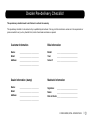
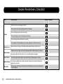
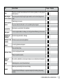
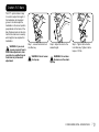
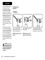
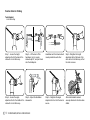
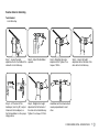
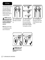
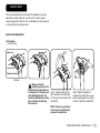
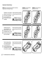
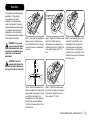
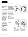
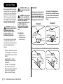
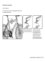
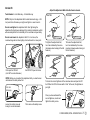
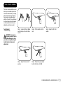
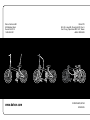
SERVICE INSTRUCTIONS
Contents
Dealer Pre-Delivery Checklist......................................... 3
Dahon F.I.T. Stem ............................................................. 7
Axis Stem ......................................................................... 8
VRO Stem ....................................................................... 12
Andros Stem .................................................................. 13
Handlepost Hinge .......................................................... 15
Headset .......................................................................... 17
Frame Latch ................................................................... 18
LockJaw Hinge Adjustment . ........................................ 22
Kore I-Beam Saddle ...................................................... 27
Neos Derailleur .............................................................. 28
2
© 2009 DAHON, BPSA • 2009.09.DS.EN
Dealer Pre-delivery Checklist
This pre-delivery checklist needs to be filled out to activate the warranty.
This pre-delivery checklist is to be carried out by a qualified bicycle mechanic. If at any point the mechanic is unclear as to the requirements or
process needed to carry out any checklist item, he/she should seek assistance as required.
Customer Information
Bike Information
Name: _________________________
Model: ___________________________
Address:
_________________________
Serial #:
___________________________
Email: _________________________
_________________________
Year:
___________________________
Dealer Information (stamp)
Mechanic Information
Name: _________________________
Signature: ___________________________
Address:
_________________________
Email: _________________________
_________________________
Name: ___________________________
Date of check:___________________________
© 2009 DAHON, BPSA • 2009.09.DS.EN
3
Dealer Pre-delivery Checklist
Part
Item to Check
The frame is free from damage or defect.
All frame joints are free from physical defect or damage.
Frame
The main hinge(s) opens and closes freely.
The main hinge(s) is free from all play when locked.
The main hinge safety latch functions correctly.
Any magnetix fold holding latches are securely tightened on both front and rear.
Brake Levers
Brake Cables
Moves and returns freely with the brake cable seated correctly within the lever.
Calipers can move freely, are free from damage, and the cable locking nut is secure.
Any excess cable should be tied or cut to a sensible length and capped.
Brake Blocks
Are correctly positioned to make contact with the rim. Retaining nuts are secure.
Brake Calipers
Front and rear calipers are correctly centered, movement is smooth and effective in
gripping the wheel rim.
Drivetrain
Pedal, cranks, chain rings, bottom bracket and derailleur(s) are securely fastened and
correctly aligned.
4
© 2009 DAHON, BPSA • 2009.09.DS.EN
Passed
Remarks
Part
Item to Check
Passed
Chain
The chain is correctly tensioned between the front and rear sprockets, free from physical
defects and rust.
Chain and gear
selector assembly
Moves freely and correctly through the gear selections, and are correctly aligned in all
gears.
Remarks
Cable locking nut is secure.
Derailleur(s)/hub
actuator
Any excess cable should be tied or cut to a sensible length and capped.
Gear selection
Mechanism is securely fixed to the handlebars.
Chain guard
Is free from physical defect or damage, is correctly positioned. Retaining nuts are secure.
Handlebar and
handlepost
Are free from physical defect or damage.
Handlepost, stem,
handlebar
All bolts are secure and correctly tightened.
Headset
Is correctly tightened and adjusted.
Opens and closes freely.
Handlepost hinge
Is free from all play when locked.
Safety lock operates correctly.
Saddle and
seatpost
All seat bolts, saddle bolts, and seat quick releases are correctly tightened and adjusted.
Saddle
Saddle alignment is correct (forward and level)
Slides freely and smoothly in the frame for folding.
Seatpost
(For bikes fitted with PostPumps or suspension seatposts) Functioning and operating
correctly.
© 2009 DAHON, BPSA • 2009.09.DS.EN
5
Part
Tires
Item to Check
Are free from physical damage or defect, are correctly seated in the right direction.
Have the correct air pressure, dust caps are present on the valves.
Wheel rims, bearings and spokes are free of physical damage or defect.
Wheels
Wheel nuts and spoke nipples are tight.
Front and rear wheel are free from wobble or buckle, do not foul the brake blocks,
mudguards, or anything else.
Wheel quick release
Are correctly installed and adjusted.
Wheel bearings
Are correctly adjusted.
Reflectors
Are both present and securely fastened to the front and rear wheels, at the front of
the bike and at the rear of the bike.
Bell
Is present and securely fastened to the handlebar
Accessories
Mudguards, racks, kickstands, and supports are firmly attached to the bodywork,
all supports are in place and tight.
Lights
Lights and wiring are firmly attached and functioning correctly. If a dynamo hub is
fitted, check that rotation direction is correct.
Owner Manual
The correct owner manual is supplied with the bicycle.
Support bracket functions correctly.
Magnetix is correctly aligned.
Folding and
unfolding
Bike folds completely.
Bike stands stably when folded.
Bike unfolds completely.
6
© 2009 DAHON, BPSA • 2009.09.DS.EN
Passed
Remarks
Dahon F.I.T. Stem
The F.I.T. system makes it easy
for a rider to adjust the height of
the handlebars. An integrated
groove in the stem keeps the
handlebars in the correct position
perpendicular to the frame of the
bike. Distance marks on the stem
itself let the rider know to exactly
what height he has adjusted his
handlebars.
WARNING: If you are in
any way unsure of how to
make these adjustments, take
your bike to a qualified bicycle
technician for professional
adjustment.
5mm
5mm
Step 1 - Loosen the bolt with a 5
mm Allen key.
WARNING: Do not loosen
the top cap.
Step 2 - Adjust the stem to the
desired height.
Step 3 - Tighten the bolt with a
5 mm Allen key. Tighten it with a
torque of 10 Nm.
WARNING: Do not raise
the stem over the stem’s
top cap.
© 2009 DAHON, BPSA • 2009.09.DS.EN
7
Axis Stem
The newly developed Axis stem
makes it easy for a rider to
adjust the height and angle of
the handlebars. An integrated
groove in the stem keeps the
handlebars in the correct position
perpendicular to the frame of the
bike while an adjustment joint
in the middle of the stem allows
for angle adjustments. Distance
marks on the stem itself let
the rider know to exactly what
height the handlebars have been
adjusted.
Additionally, a second groove
in the stem makes it possible to
take off the stem and handlebar,
reposition it 90 degrees and put
it back onto the handlepost. In
this way, the stem and handlebar
can be securely attached to the
bike when it is folded and stored
instead of dangling loosely from
the bike.
Handlebar Height
Adjustment
Tools Needed:
• 5 mm Allen Key
Step 1 - Loosen the height
adjustment bolt at the back of the
stem with a 5 mm Allen key.
Step 2 - Adjust the stem to the
desired height.
WARNING: Do not loosen the
top cap.
WARNING: Do not raise the
stem over the stem’s top cap.
WARNING: If you are in
any way unsure of how to
make these adjustments, take
your bike to a qualified bicycle
technician for professional
adjustment.
8
© 2009 DAHON, BPSA • 2009.09.DS.EN
Step 3 - Retighten the height
adjustment bolt with a 5 mm Allen
key. Tighten it to a torque of 10 Nm.
Adjust Handlebar Angle
Tools Needed:
• 4 mm Allen Key
• 5 mm Allen Key
Step 1 - Loosen the angle
adjustment bolt in the middle of the
stem with a 5 mm Allen key.
Step 2 - Adjust the stem to the
desired angle.
4mm
4mm
Step 4 - Loosen (but do not
remove) the plate bolts with a 4
mm Allen key until the handlebar
can be rotated.
Step 3 - Retighten the angle
adjustment bolt to a torque of 10
Nm.
Step 5 – Adjust the handlebar to
desired position. The angle should
allow your fingers to easily reach
the brake levers.
Step 6 – Tighten the plate bolts
with a 4 mm Allen key. Tighten to
a torque of 8 Nm.
© 2009 DAHON, BPSA • 2009.09.DS.EN
9
Position Stem for Folding
Tools Needed:
• 5 mm Allen Key
Step 1 - Loosen the height
adjustment bolt at the back of the
stem with a 5 mm Allen key.
Step 2 – Lift the stem off the
handlepost, turn it counterclockwise by 90°, and put it back
onto the handlepost.
Handlebar and front wheel should
now be parallel to each other.
Step 3 - Retighten the height
adjustment bolt at the back of the
stem with a 5 mm Allen key so that
the stem is secure.
Step 4 - Loosen the angle
adjustment bolt in the middle of the
stem with a 5 mm Allen key.
Step 5 – Adjust the handlebar
downwards.
Step 6 – Retighten the angle
adjustment bolt so that the stem is
secure.
Stem and handlebar remain
securely attached to the bike when
folded.
10
© 2009 DAHON, BPSA • 2009.09.DS.EN
Position Stem for Unfolding
Tools Needed:
• 5 mm Allen Key
Step 1 - Loosen the angle
adjustment bolt in the middle of the
stem with a 5 mm Allen key.
Step 2 – Adjust the handlebar
upwards.
Step 3– Retighten the angle
adjustment bolt. Tighten it to a
torque of 10 Nm.
Step 5 – Lift the stem off the
handlepost, turn it by 90°, and put
it back onto the handlepost, so
that the handlebar is in the proper
riding position.
Step 6 - Retighten the height
adjustment bolt at the back of
the stem with a 5 mm Allen key.
Tighten it to a torque of 10 Nm..
Handlebar and front wheel should
now be perpendicular to each
other.
Step 4 - Loosen the height
adjustment bolt at the back of the
stem with a 5 mm Allen key.
© 2009 DAHON, BPSA • 2009.09.DS.EN
11
VRO Stem
With the VRO clamp the handlebar
can be easily adjusted to fit the
rider’s height or desired riding
position by moving it forwards,
backwards, up and down. The
following instructions explain how
to adjust the VRO clamp.
WARNING: If you are in
any way unsure of how to
make these adjustments, take
your bike to a qualified bicycle
technician for professional
adjustment.
Step 1 - Loosen the bolts of the
VRO clamps with a 5 mm Allen
key.
NOTE: Make sure that the angle
of the handlebar allows you easy
access to the brake levers.
WARNING: Make sure that
the outside faces of the
clamps are aligned to the stem
mount T-bar.
12
© 2009 DAHON, BPSA • 2009.09.DS.EN
Step 2 - Adjust the height and
position of the handlebar to
achieve your preferred riding
position. Move the VRO clamp
within the “window of adjustment” front, backwards, up, and down.
Step 3 - After establishing the
desired position, tighten the bolts
of the VRO clamps with a torque
of 10 Nm.
Andros Stem
The newly developed Andros stem allows the handlebar to be easily
adjusted in seconds without the use of tools to fit a rider’s height or
desired riding position. With the stem, the handlebar can also be placed
in a flat position when folding the bike.
Andros Stem Adjustment
Tools Needed:
• 5 mm Allen Key
Safety Lock
Lock Lever
Tightening Screws
Overview
Make sure that the
tightening screws are first
tightened with a 5 mm Allen key
to a torque of 7.5 Nm before you
start adjusting the stem. The
screws are tightened by turning
them clockwise when facing
them head-on.
Step 1 - Open the safety lock on
top of the Andros stem by sliding
it to the right when facing the stem
from behind.
Step 2 - Adjust the height and
position of the Andros stem to your
preferred riding position by rotating
it within its “window of adjustment”.
NOTE: You have to push down
on the lock lever slightly when
you open the safety lock.
© 2009 DAHON, BPSA • 2009.09.DS.EN
13
Andros Stem Adjustment
(continued)
NOTE: Make sure that the angle of the handlebar allows easy
access to the brake levers.
NOTE: Make sure that the safety lock is closed when you cycle.
NOTE: Regularly apply grease to the joints to avoid rust.
WARNING: Make sure that the tightening screws are tightened to a
torque of 7.5 Nm before you start cycling.
Step 4 - While establishing the
desired position, make sure that
the handlebar is readjusted to
the right position. The angle of
the handlebar should allow your
fingers to easily reach the brake
levers.
You can adjust the height and
position of the Andros stem to
achieve your preferred riding
position. Move the Andros stem
within the “window of adjustment”.
Some suggested riding positions:
14
Step 5 – After the handlebar
has been placed in the desired
position, close the lock lever until
the safety lock closes with an
audible “click”.
Flat For folding
© 2009 DAHON, BPSA • 2009.09.DS.EN
High
City driving position
Lower
Treking driving
position
Low
Road driving
position
Handlepost Hinge
CAUTION: Do NOT cycle with a loose handlepost
hinge.
The Different Handlepost Hinges
open
closed
radius v
The latch of the handlepost hinge on Dahon folding
bikes should be checked before each ride to make sure
that it closes tightly to secure the handlepost. A closed
handlepost hinge with a properly adjusted and secured
latch should have little to no side-to-side movement. Inspect
the handlepost periodically to ensure that it is properly
adjusted.
Different versions of the handlepost hinge can be found on
Dahon bikes. They look slightly different, but the adjustment
of the hinge latch is basically the same for both versions.
Please check the handlepost hinge to find out which hinge
version is used and follow the appropriate instructions for
adjusting the latch.
NOTE: For details about how to open the hinge, please
refer to the included “folding instructions”.
These instructions are only for the adjustment of the hinge
itself. Regarding the adjustment of the headset, please refer
to the “headset instructions”.
Eco
WARNING: If you are in any way unsure of how to
make these adjustments, take your bike to a
qualified bicycle technician for professional
adjustment.
radius
To check if the latch needs to be adjusted, close the
handlepost hinge and then close the hinge latch. If the
latch is loose after closing or if too much force is required to
close it, then the latch needs to be adjusted.
© 2009 DAHON, BPSA • 2009.09.DS.EN
15
Adjusting the Handlepost Hinges
Eco
radius
radius v
NOTE: Adjust in small (1/16) turn increments to avoid over
tightening or over loosening the hinge.
16
The Radius V can be adjusted
(tightened or loosened) with a
6 mm wrench. An adjustable
wrench or small pliers can
be used if a 6 mm wrench is
unavailable.
Adjust the latch bolt until the latch
opens and closes with 29~49 N of
force.
The Radius hinge can be
adjusted (tightened or loosened) with an 8 mm wrench.
An adjustable wrench or small
pliers can be used if an 8 mm
wrench is unavailable.
Adjust the latch bolt until the latch
opens and closes with 29~49 N of
force.
The Eco Handlepost Hinge
can be adjusted (tightened
or loosened) with a 6 mm
wrench. An adjustable wrench
or small pliers can be used if a
6 mm wrench is unavailable
Adjust the latch bolt until the latch
opens and closes with 29~49 N of
force.
WARNING: If the hinge is
over tightened the tension
can cause damage to the hinge.
WARNING: If the hinge is
over tightened the tension
can cause damage to the hinge.
WARNING: If the hinge is
over tightened the tension
can cause damage to the hinge.
© 2009 DAHON, BPSA • 2009.09.DS.EN
Loosen: Turn the latch bolt as
indicated by the arrow.
Tighten: Turn the latch bolt as
indicated by the arrow.
Headset
Your headset should be checked
periodically. If there is play
or looseness in the fork or
handlepost, the headset may
need to be adjusted. A properly
adjusted headset eliminates play
or looseness while allowing the
handlebars to be turned easily.
The following instructions explain
how to adjust the headset.
WARNING: If you are in
any way unsure of how to
make these adjustments, take
your bike to a qualified bicycle
technician for professional
adjustment.
Step 1 - First open the handlepost
clamp. Loosen the clamp screw
with a 6 mm Allen key by turning it
counter-clockwise as indicated by
the arrow.
Step 2 - Tighten the headset screw
with a 10 mm Allen key. Turn
the headset screw clockwise as
indicated by the arrow. Tighten the
screw with a torque of 6.8~11.3
Nm.
Step 4 - After the adjustment and
before you tighten the clamp screw
again please check again to make
sure that the handlepost and
handlebar are in correct alignment,
and that they are perpendicular
to the front wheel as shown in the
picture above.
Step 5 - Tighten the clamp screw
by turning it clockwise as indicated
by the arrow. Tighten the screw
with a torque of 11.3 Nm.
Step 3 - Occasionally apply some
Loctite 222 (Loctite 242 is also
acceptable) to the clamp screw.
In this case take out the clamp
screw and place a small drop of
Loctite 222 (or Loctite 242) on the
threads of this screw. Then replace
the clamp screw.
WARNING: Failure to
appropriately tighten the
headset can lead to damage to
the bicycle or injury to the rider.
© 2009 DAHON, BPSA • 2009.09.DS.EN
17
Frame Latch
The frame hinge is the most
important part of a folding bicycle.
Care should be taken to check
that the hinge is adjusted correctly
before each ride.
Your frame hinge will need periodic
adjustment. If there is play or
looseness in the frame it may need
to be adjusted. A properly adjusted
hinge eliminates play or looseness
and a correctly tightened hinge will
close with a strong seal, and the
frame will feel solid.
WARNING: If you are in
any way unsure of how to
make these adjustments
yourself, take your bike to a
qualified technician for
professional adjustment.
WARNING: Failure to
appropriately tighten the
frame latch can lead to damage
to the bicycle or injury to the
rider. Do NOT cycle with a loose
frame hinge.
The ViseGrip™ Hinge (also
applies to the Eco frame’s
hinge)
Use a 6mm wrench (if you do not
have the right sized wrench you
can also use an adjustable wrench
or small pliers) to tighten or loosen
the hinge.
Adjust the hinge bolt so that the
hinge opens and closes with the
correct amount of force which is
49~59 N for aluminum frames and
29~59 N for steel frames.
FRAME HINGE open
NOTE: Adjust in 1/16-turn
increments only, otherwise you will
quickly over-tighten or over-loosen
the hinge.
Tools Needed:
• 10 mm wrench
• 6 mm Allen key
Dahon uses a variety of frame
hinges on its bikes. Please check
your bike to see which of the
following instructions is applicable.
18
FRAME HINGE closed
© 2009 DAHON, BPSA • 2009.09.DS.EN
Tighten: Turn the hinge latch
bolt downwards (facing the hinge
head on) as indicated by the
arrow.
Loosen: Turn the hinge latch bolt
upwards (facing the hinge head
on) as indicated by the arrow.
The V-Clamp Hinge
Version A
There are a several versions of the V-Clamp. Instructions on adjusting
the V-Clamp are provided below. Please check your bike to determine
which V-Clamp version is used and apply the appropriate instructions.
See the different versions below, and how to differentiate them.
Adjust the hinge bolt so that the hinge opens and closes with the
correct amount of force, which is 39~88 N.
NOTE: Adjust in 1/16-turn increments only, otherwise you will quickly
over-tighten or over-loosen the V-Clamp hinge.
WARNING: If the hinge is over tightened the tension can
cause damage to the frame.
Version B
Hinge clamp on the frame’s front
half.
Open the hinge to adjust itttt.
Use an 8 mm wrench to adjust.
Hinge clamp on the frame’s back
half.
Open the hinge to adjust it.
Use an 8 mm wrench to adjust.
Version C
Hinge clamp on the frame’s front
half. The adjustment nut is on
the outside. A 6 mm Allen key is
needed to adjust it.
Lock Nut
Open the hinge before adjusting it.
The lock nut needs to be loosened
with a 10 mm wrench.
© 2009 DAHON, BPSA • 2009.09.DS.EN
19
Adjust the hinge bolt so that the hinge opens and closes with the
correct amount of force which is 39~88 N.
NOTE: Adjust in 1/16-turn increments only, otherwise you will quickly
over-tighten or over-loosen the V-Clamp hinge.
WARNING: If the hinge is over tightened the tension can
cause damage to the frame.
*TOOLS NEEDED: 8 mm wrench
Version A*
Tighten: Turn the hinge clamp
bolt counter- clockwise as
indicated by the arrow (facing the
hinge turn the screw upwards).
Loosen: Turn the hinge clamp
bolt clockwise as indicated by the
arrow (facing the hinge turn the
screw downwards).
Version B*
Tighten: Turn the hinge clamp
bolt counter- clockwise as
indicated by the arrow (facing the
hinge turn the screw downwards).
* Use an 8 mm wrench (you can also use an adjustable wrench or small pliers) to adjust the hinge.
20
© 2009 DAHON, BPSA • 2009.09.DS.EN
Loosen: Turn the hinge clamp
bolt clockwise as indicated by the
arrow (facing the hinge turn the
screw upwards).
Adjust the hinge bolt so that the hinge opens and closes with the
correct amount of force which is 39~88 N.
NOTE: Adjust in 1/16-turn increments only, otherwise you will quickly
over-tighten or over-loosen the V-Clamp hinge.
WARNING: If the hinge is over tightened the tension can
cause damage to the frame.
*TOOLS NEEDED: 10 mm wrench, 6 mm Allen key
Version C*
Step 3 - To tighten the hinge
clamp, use a 6 mm Allen Key. Turn
the adjustment nut clockwise as
indicated by the arrow.
Step 3 - To loosen the hinge
clamp, use a 6 mm Allen Key.
Turn the adjustment nut counterclockwise as indicated by the
arrow.
Step 1 - Loosen the Lock Nut: Use
a 10 mm wrench. Turn the wrench
as indicated by the arrow.
Step 2 - Close the hinge, but do
not close the latch.
Check the tightness of the clamp
by opening and closing the hinge
latch.
Step 4 - Tighten the Lock Nut:
After adjusting the hinge, use a
10 mm wrench to tighten the lock
nut again. Turn the wrench as
indicated by the arrow.
NOTE: Hold the adjustment nut
tight with an Allen key, while
tightening the lock nut.
© 2009 DAHON, BPSA • 2009.09.DS.EN
21
LockJaw Hinge
Bikes equipped with the LockJaw
hinge look just like a regular bike –
you have to get up close and look
really hard to see where the bike
folds. To ensure safe and trouble
free usage of the LockJaw hinge
and your bike, please read the
following instructions carefully.
WARNING: If you are in
any way unsure of how to
make these adjustments
yourself, take your bike to a
qualified technician for
professional adjustment.
The LockJaw hinge (one located
on the top tube and one on the
down tube) has three components
with each fulfilling a different
function.
WARNING: ONLY open
the LockJaw hinge with
the OC bolt.
WARNING: As a general
rule, the pivot bolt will
not need any user adjustment.
Do NOT try to open the
LockJaw hinge with the pivot
bolt. ONLY adjust the
tightness of the LockJaw
hinge with the adjustment
bolt.
Tools Needed:
• 6 mm Allen key
• 2.5 mm Allen key
• 2 mm Allen key
• OC Bolt – opens and closes the
LockJaw hinge. It is secured by
a special Safety Screw (Version
B only).
• Adjustment Bolt – adjusts
the tightness of the LockJaw
mechanism.
• Pivot Bolt – the actual hinge
axle around which the two
halves of the frame rotates. The
pivot bolt can be adjusted to
tighten or loosen the hinge.
22
© 2009 DAHON, BPSA • 2009.09.DS.EN
Overview
There are two versions of the
LockJaw. Please check your
bike to determine which LockJaw version is used and apply
the appropriate instructions.
For Version B the Adjustment
Bolt contains an additional safety screw (inside the Adjustment
Bolt. See the different versions
below.
Version B
Version A
OC Bolt
OC Bolt
Adjustment
Bolt
Adjustment
Bolt
Pivot Bolt
Pivot Bolt
Safety
Screw
The Lock Screw and the Pivot Bolt are the same for both versions.
Lock Screw
Lock Screw
Adjustment
Bolt
Adjustment
Bolt
Pivot
Bolt
Pivot
Bolt
Open/Close the LockJaw Hinge
Use a 6 mm Allen key.
For instructions on how to fold a LockJaw equipped bike, please refer to
the included folding instructions.
To unlock the LockJaw hinge, turn
the OC bolt counter-clockwise by
180º.
To lock the LockJaw hinge,
close the hinge and turn the
OC bolt clockwise by 180º. If
the adjustment bolt is properly
adjusted, you should feel a
slight “click” and the teeth of the
LockJaw hinge will draw together.
© 2009 DAHON, BPSA • 2009.09.DS.EN
23
Adjust the Adjustment Bolt while the frame is closed.
Adjust the Tightness of the LockJaw (The Adjustment Bolt)
The LockJaw is exceptionally stiff and stable, but will require period
inspection and adjustment to ensure that it is properly tensioned.
Adjust the LockJaw according to the following instructions.
TIGHTEN
LOOSEN
Version A
Tools Needed: 6 mm Allen key
NOTE: Only turn the adjustment bolt in small increments (e.g. a 1/8
turn) each time otherwise you might over tighten or over loosen it.
Do not over tighten the adjustment bolt. Over tightening the
adjustment bolt will cause damage to the meshing mechanism, which
will eventually affect the functionality of the LockJaw and your safety.
Do not over loosen the adjustment bolt. If it is too loose, the
LockJaw hinge will not close tightly, which will result in a loose joint.
To tighten the adjustment bolt,
turn it as indicated by the arrow
(clockwise when looking at the bolt
head-on)
OPEN
To loosen the adjustment bolt,
turn it as indicated by the arrow
(counter-clockwise when looking at
the bolt head-on)
CLOSE
To check the correct tightness of the LockJaw close and open the OC
bolt. When the OC bolt closes with a “click” at the end, the tightness is
just right.
First open the OC Bolt
(turn 180º counter-clockwise)
24
But DO NOT open the frame
© 2009 DAHON, BPSA • 2009.09.DS.EN
Once you have achieved the correct tightness, close the LockJaw
by turning the OC bolt 180º counter-clockwise.
Version B
Tools Needed: • 6 mm Allen key • 2.5 mm Allen key
Adjust the Adjustment Bolt while the frame is closed.
TIGHTEN
LOOSEN
NOTE: Only turn the adjustment bolt in small increments (e.g. a 1/8
turn) each time otherwise you might over tighten or over loosen it.
Do not over tighten the adjustment bolt. Over tightening the
adjustment bolt will cause damage to the meshing mechanism, which
will eventually affect the functionality of the LockJaw and your safety.
Do not over loosen the adjustment bolt. If it is too loose, the
LockJaw hinge will not close tightly, which will result in a loose joint.
To tighten the adjustment bolt,
turn it as indicated by the arrow
(clockwise when looking at the bolt
head-on)
OPEN
First open the OC Bolt
(turn 180º counter-clockwise)
CLOSE
But DO NOT open the frame
NOTE: Before you can adjust the adjustment bolt, you must loosen
and remove the safety screw first.
2.5 mm
Allen key
Loosen the safety screw by
turning it counter-clockwise
To loosen the adjustment bolt,
turn it as indicated by the arrow
(counter-clockwise when looking at
the bolt head-on)
Then remove the safety screw
To check the correct tightness of the LockJaw close and open the OC
bolt. When the OC bolt closes with a “click” at the end, the tightness is
just right.
Once you have achieved the
correct tightness, insert and
tighten the safety screw.
© 2009 DAHON, BPSA • 2009.09.DS.EN
25
The Pivot Bolt
WARNING: Under normal
use, the pivot bolt should
not need adjustment. If the pivot
bolt needs adjustment please
have it serviced by a certified
bicycle technician.
When the LockJaw is unlocked,
the frame can rotate around the
pivot bolt. Follow the following
instructions to adjust (loosen/
tighten) the pivot bolt. Sometimes
it might be difficult to rotate the
frame because the pivot bolt is too
tight (one reason for this is that
you may have accidently affected
the tightness of the pivot bolt while
you were adjusting the adjustment
bolt).
Step 1 - Open the lock screw with
a 2 mm Allen key.
Step 2 (Loosen) - Turn the pivot
bolt counter-clockwise to loosen it
as indicated by the arrow (6 mm
Allen key).
Step 2 (Tighten) - Turn the pivot
bolt clockwise to tighten it as indicated by the arrow (6 mm Allen
key).
A 2 mm Allen key and a 6 mm Allen key are needed to adjust the
pivot bolt.
The pivot bolt and its lock screw
are on the bike’s non-chain side.
NOTE: Only turn the pivot bolt in
small increments (e.g. a 1/8 turn)
each time otherwise you might
over tighten or over loosen it.
26
© 2009 DAHON, BPSA • 2009.09.DS.EN
Step 3 - When you are finished
close the lock screw with a torque
of 1 Nm.
Kore I-Beam Saddle
The Kore I-beam saddle is a revolutionary new saddle system that
cuts down dramatically on weight,
while at the same time allowing
the maximum in saddle adjustability to the rider. The saddle can
be moved forward and backward
on the rail, while the tilt can be
adjusted up or down as well.
Tools Needed:
• 4 mm Allen Key
WARNING: If you are in
any way unsure of how to
make these adjustments, take
your bike to a qualified bicycle
technician for professional
adjustment.
Step 1 - Loosen the Kore I-Beam
seat rail clamp with a 4mm Allen
wrench.
Step 2 - Fit the saddle onto the
rails.
Step 4 - Adjust the fore and aft
position.
Step 5 - Tighten the pre-greased
bolts to 85 in/lbs or 9.5 NM.
Step 3 - Adjust the tilt of the
saddle.
© 2009 DAHON, BPSA • 2009.09.DS.EN
27
Dahon Neos Derailleur
The original low-profile Dahon Neos derailleur is
specially designed for small wheels. The Neos
allows for twice as much ground clearance than a
conventional derailleur and the cache technology
means that the derailleur body lies flush underneath
the chain stays. In this way the derailleur body only
projects 12 mm from the chain stays and is much
more protected than a derailleur which protrudes
by up to 40 mm. And the new Neos 2.0 is the next
evolutionary step with upgraded materials and
reduced weight.
Dahon Neos Derailleur
Conventional Derailleur
Adjustment Screws
WARNING: If you are in any way unsure of
how to make these adjustments yourself,
take your bike to a qualified technician for
professional adjustment.
Wire Adjustment Bolt
Due to its special design the Dahon Neos derailleur’s
position differs from that of a conventional derailleur.
Compared to a conventional derailleur it is aligned in
the opposite direction, i.e. the adjustment screws and
the wire adjustment bolt are facing forward.
But nevertheless, you can adjust it like any other
derailleur. Please follow the instructions below.
Wire Tension
Adjustment Bolt
High Adjustment Screw
Low Adjustment Screw
Wire Fastening Bolt
28
© 2009 DAHON, BPSA • 2009.09.DS.EN
High Adjustment
Turn the top adjustment screw to adjust so that the
guide pulley is below the outer line of the smallest
sprocket when looking from the rear.
© 2009 DAHON, BPSA • 2009.09.DS.EN
29
Low Adjustment
Turn the low adjustment screw so that the guide pulley
moves to a position directly in line with the largest
sprocket.
30
© 2009 DAHON, BPSA • 2009.09.DS.EN
Index Shifting Adjustment
Use the shifter while turning the
crank arm to move the derailleur to
the largest sprocket. Then operate
shifter once to move the derailleur
to the 2nd-gear sprocket. After this
operate the shifter just as far as
the extent of play, and then turn
the crank arm.
When changing to the
3rd gear sprocket.
3
2
Turn the cable
adjustment bolt
clockwise to tighten it
until the chain returns to
the 2nd sprocket.
Best Setting
3
If shifting
2 3 to 2nd is not
22
possible, or shifting to
2nd occurs but noise
of the chain contacting
the largest sprocket is
heard.
2
2
Change to 2nd
and turn the screw
counterclockwise until
no noise is heard.
2
32
2 2
2
2
The best setting is when the
cable adjustment bolt is tightened
(turned clockwise) until noise
occurs without the shifter being
operated, and then loosened
(turned counterclockwise) 360
degrees from that point.
Operate shifter to change gears,
and check that no noise occurs in
any of the gear positions.
© 2009 DAHON, BPSA • 2009.09.DS.EN
31
Dahon California INC.
833 Meridian Street
Duarte CA 91010
1-800-442-3511
www.dahon.com
Dahon TW
8F-8, #6, Lane 609, Chung Hsin RD., Sec 5
San Chung, Taipei Hsien ROC 241, Taiwan
+886-2-2999-5623
© 2009 DAHON, BPSA
2009.09.EN