1
DATAPROCESS EUROPE S.p.A.
Programming Manual
Release 1.3
DATAPROCESS EUROPE S.p.A.
Viale Dell’Artigianato, 19
Binasco (MI)
Tel. 02- 900221 Fax 02- 900913
UV521UPG
ST3xx ST4xx ST5xx – PROGRAMMING MANUAL - Pag.1
DATAPROCESS EUROPE S.p.A.
1
Introduction................................................................................................................. 5
2
Technical specifications.............................................................................................. 5
3
Description of the Printer ........................................................................................... 5
4
Test label...................................................................................................................... 6
5
Operating status .......................................................................................................... 8
6
Led indicators .............................................................................................................. 8
6.1 POWER LED..................................................................................................................... 8
6.2 LINE LED .......................................................................................................................... 8
6.3 PRINT LED ....................................................................................................................... 8
7
Keys.............................................................................................................................. 9
7.1 Pause key............................................................................................................................ 9
7.2 Feed key.............................................................................................................................. 9
8
Using the keys.............................................................................................................. 9
8.1.1
8.1.2
8.1.3
8.1.4
Abort ........................................................................................................................................ 9
Reset ........................................................................................................................................ 9
Recall of a macro ..................................................................................................................... 9
Calibration ............................................................................................................................. 10
9
Auto calibration......................................................................................................... 10
10
Connection to External Devices ............................................................................... 11
10.1
Serial............................................................................................................................. 11
10.2
Parallel ......................................................................................................................... 11
10.3
Network........................................................................................................................ 12
11
Serial communication protocols............................................................................... 12
12
Network communication protocols........................................................................... 13
13
Printer control commands ........................................................................................ 15
14
Control characters..................................................................................................... 15
14.1
ENQ .............................................................................................................................. 15
14.2
BS.................................................................................................................................. 15
14.3
LF ................................................................................................................................. 15
14.4
FF.................................................................................................................................. 15
14.5
CR................................................................................................................................. 15
15
Commands with absolute priority............................................................................. 16
15.1
VT-US-US-NAK .......................................................................................................... 16
15.2
SO-US-US-NAK .......................................................................................................... 16
15.3
SI-US-US-NAK............................................................................................................ 16
ST3xx ST4xx ST5xx – PROGRAMMING MANUAL - Pag.2
DATAPROCESS EUROPE S.p.A.
15.4
DLE-US-US-NAK ........................................................................................................16
16
Printable characters.................................................................................................. 16
17
The "/" command to programme the printer ......................................................... 21
17.1
// .....................................................................................................................................21
17.2
/!.....................................................................................................................................21
17.3
/# ....................................................................................................................................21
17.4
/@ ..................................................................................................................................21
17.5
/ $&%nnnnnnnnnnnnnnnn ........................................................................................21
17.6
/$%&.............................................................................................................................22
17.7
/$>Ann ..........................................................................................................................22
17.8
/$>Bbdps.......................................................................................................................22
17.9
/$>Ch.............................................................................................................................23
17.10
/$>Ln00.........................................................................................................................23
17.11
/$>Ohhmmssggmmaaaa..............................................................................................23
17.12
/$>Paaabbbcccppprrr .................................................................................................24
17.13
/ $>Tiiihbbbyyyyffffmmmmnnnnttttpppp................................................................26
17.14
/*Ax solo ST4xx ST5xx................................................................................................26
17.15
/*Bn ...............................................................................................................................26
17.16
/*Dx solo ST4xx ST5xx................................................................................................27
17.17
/*Txx solo ST4xx ST5xx ..............................................................................................27
17.18
/*Oo...............................................................................................................................28
17.19
/a – Only for ST4xx ST5xx.........................................................................................28
17.20
/Awrc.............................................................................................................................28
17.21
/Bthhhc..ce ....................................................................................................................29
17.22
/C ...................................................................................................................................32
17.23
/Exxxxyyyy....................................................................................................................32
17.24
/Ffhv ..............................................................................................................................32
17.25
/Gxxxxyyyy ...................................................................................................................34
17.26
/Hnnnn ..........................................................................................................................34
17.27
/Iv... ...............................................................................................................................35
17.27.1
17.27.2
17.27.3
17.27.4
17.27.5
17.27.6
17.27.7
/I0 ...................................................................................................................................... 35
/I1nv.. vmqqss ................................................................................................................... 35
/I2ssssnnc.. c...................................................................................................................... 35
/I3ssssthhhc.. ce................................................................................................................. 36
/I4ssssbbbllll...................................................................................................................... 36
/I5ssssnncc.. c.................................................................................................................... 36
/I6nndd..dssssthhhccc...ce ................................................................................................. 37
ST3xx ST4xx ST5xx – PROGRAMMING MANUAL - Pag.3
DATAPROCESS EUROPE S.p.A.
17.28
/Jhhss ............................................................................................................................ 38
17.29
/Kpdet........................................................................................................................... 38
17.30
/Ldlllltt ......................................................................................................................... 39
17.31
/Mwwwwhhhhttt ......................................................................................................... 40
17.32
/Nssssoooo .................................................................................................................... 40
17.33
/Psss .............................................................................................................................. 41
17.34
/Qbbbllllg.. g ................................................................................................................ 42
17.35
/Roc............................................................................................................................... 42
17.36
/Tn................................................................................................................................. 43
17.37
/Umm o /Uddffffffff .................................................................................................... 43
17.38
/Vssffeppp .................................................................................................................... 44
17.39
/Wnnnn......................................................................................................................... 44
17.40
/Xiiippp......................................................................................................................... 45
17.41
/Yb.. b ........................................................................................................................... 45
17.42
/Z................................................................................................................................... 45
18
Return Codes ............................................................................................................. 46
19
Status of the buffer.................................................................................................... 46
20
Status of the sensors.................................................................................................. 47
21
Status of the printer................................................................................................... 47
22
MACRO ..................................................................................................................... 49
23
Communication Ports ............................................................................................... 49
23.1
Serial Ports ST3xx ST4xx ST5xx ............................................................................... 50
23.2
Parallel Port – only for ST4xx ST5xx ...................................................................... 51
23.3
Industrial Interface – only for ST4xx ST5xx............................................................ 51
23.3.1
23.3.2
Output (relè) "D" 9 pin male.................................................................................................. 51
Input (optoisolated) "D" 9 pin female.................................................................................... 52
23.4
Applicator interface – only for ST4xx ST5xx.......................................................... 53
23.5
Rewinder interface – only for ST4xx ST5xx............................................................ 53
ST3xx ST4xx ST5xx – PROGRAMMING MANUAL - Pag.4
DATAPROCESS EUROPE S.p.A.
1 Introduction
This document describes the programming commands for the ST302, ST312, ST314,
ST403, ST406 printers.
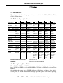
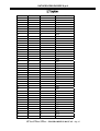
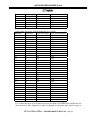
2 Technical specifications
St302
St312
St403
St406
St514
St516
Direct
thermal
Ther. transfer
8dot
Direct
thermal
Ther. transfer
8dot
Direct
thermal
Ther. transfer
8dot
Direct
thermal
Ther. transfer
8dot
Direct
thermal
Ther. transfer
8dot
Print method
Direct
mal
Resolution
8dot
Print speed
20-170mm/s
20-170mm/s
20-170mm/s
50-200mm/s
50-200mm/s
50-200mm/s
50-200mm/s
Paper
feed 50-200mm/s
speed
Width
Print area
56mm
Length
197mm(771)
50-200mm/s
50-200mm/s
50-250mm/s
50-250mm/s
50-250mm/s
50-250mm/s
Width 56mm
Width
104mm
Length
413mm
Width
80mm
Length
539mm(1250
)
From 40 to
90
300mm
Width
160mm
Length
1250mm
Width
104mm
Length
1250mm
Width
160mm
Length
1250mm
From
40to180
300mm
From
40to110
300mm
From
60to180
300mm
Label width
ther- Direct
thermal
Ther. transfer
8dot
St314
Length
197mm(771)
From 40 to From 10 to From
60
60
20to110
140mm
150mm
Di- 140mm
External
ameter roll
40mm
40mm
40mm
Internal
Di- 40mm
ameter roll
1Trasparency 1Trasparency 1Trasparency 2Trasparency
Label sensor
1 Reflective
230Vac
230Vac
230Vac
Power supply 230Vac
50/60Hz
50/60Hz
50/60Hz
50/60Hz
150W
150W
200W
200W
Absorption
40mm
adjustable
40-75mm
2Trasparency 2Trasparency
1 Reflective
1 Reflective
230Vac
230Vac
50/60Hz
50/60Hz
400W
400W
adjustable
40-75mm
2Trasparency
1 Reflective
230Vac
50/60Hz
400W
Weight
Height.195
Width.190
Depth.395
8kg
Height.195
Width.190
Depth.395
8.5kg
Height.245
Width.190
Depth.380
13kg
Height.545
Width.300
Depth.380
13.7kg
Height.545
Width.390
Depth.380
16kg
Height.600
Width.335
Depth.410
15kg
Height.600
Width.390
Depth.410
17kg
Interface
[speed]
RS232
[300-38400]
RS232
[300-38400]
RS232
[300-38400]
RS232
[300-38400]
Centronics
Relè Photocell.
Applicator
Rewinder
/Cutter
RS232
[300-38400]
Centronics
Relè Photocell.
Applicator
Rewinder
/Cutter
RS232
[300-38400]
Centronics
Relè Photocell.
Applicator
Rewinder
/Cutter
RS232
[300-38400]
Centronics
Relè Photocell.
Applicator
Rewinder
/Cutter
Dimensions
Label thickness :
Environmental characteristics:
Humidity:
From 60 a 200 µm (50 a 180 g/m2)
From 5 to 40 °C
From 20 to 90% non condensing
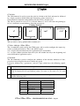
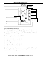
3 Description of the Printer
The ST3XX, ST4XX and ST5XX printers are equipped with a front panel having two
keys PAUSE and FEED, a red led for POWER, a green led for LINE and a yellow led for
PRINT.
On switching the printer on the POWER indicator will light up and, after a short initialisation period, the LINE indicator will also light up. If the printer is in normal operating
ST3xx ST4xx ST5xx – PROGRAMMING MANUAL - Pag.5
DATAPROCESS EUROPE S.p.A.
conditions, with labels and ribbon correctly installed, a test label will be printed (unless
deactivated in configuration). The PRINT indicator lights up during printing.
Note: Printing of the test label can be deactivated with the / $&% command.
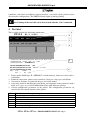
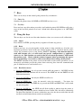
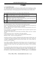
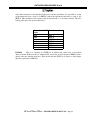
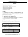
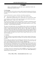
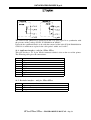
4 Test label
The test label contains the following information:
ST314
19
247
E1.4 00000
032
1
2
000
3
08:35:40
Ven 25-Apr-1997
4
>T314D10423792B583808100004390439 Ymax:297 mm. Mem:512 kb
>S6400104010100 >B28N1 >A00 >C/ >L000
P100H0290
G00000008N00000000 *02
K1000J1510V08105700 PWM:701
$&%0000000000000000
5
>P120078093187240
HON :
0:05
#LP:
5
– 21.50mV
6
#SWON:
8
KP: 0.001
1. Printer model, ROM type (E = EPROM, F = flash memory), firmware version and serial number.
2. Printhead temperature, photo sensor sensitivity (label pass, end paper, end ribbon).
3. Current date and time are printed in the grey area of the model.
4. A dot map (useful in checking the print quality and alignment of the print head) with a
black area, a grey area, vertical and horizontal lines with different spacings.
5. Current configuration parameters of the printer. The configuration parameters are
stored in the non-volatile memory of the printer.
>T
>S
>B
>A
*O
>P
P
Identification and configuration parameters of the memory
Label feed parameters
Serial interface parameters
Network address
Print orientation
Photo sensor sensitivity
Sensitivity of label photo sensor currently selected
ST3xx ST4xx ST5xx – PROGRAMMING MANUAL - Pag.6
DATAPROCESS EUROPE S.p.A.
H
G
N
K
J
V
$&%
Alignment of label (offset)
Print area x and y coordinates origin
Cutter parameters
Print mode
Print speed and image
Paper feed speed and printhead energy
Memory string and printer function selector
6. I counters used are printed in the last two lines of the test label as follows:
HON: 0:00
#SWON: 0
#LP: 0
KP: 0.000
total time the printer is switched on (hours :minutes)
number of times printer switched on
total number of labels printed
total number of kilometres of paper printed
ST3xx ST4xx ST5xx – PROGRAMMING MANUAL - Pag.7
DATAPROCESS EUROPE S.p.A.
5 Operating status
ON LINE is the normal function: the green led is on and the printer is ready to receive
data from the serial line.
PRINT mode is when the printer is printing: the yellow PRINT led is on, data reception is
suspended and the printer only accepts data for the variable fields. Subsequent print commands cannot be received and stored in the buffer unless the printer has been configured
for “double bitmap” in which case it will continue to receive data for the next label whilst
it is still printing the previous label.
OFF LINE in this mode the led is off as is the PRINT led (it will flash if there is a suspended print session), incoming data will not be processed and will be stored in the reception buffer.
6 Led indicators
There are three led indicators on the front panel protected by a membrane:
6.1 POWER LED
This indicator is red and shows that the printer is on.
6.2 LINE LED
This indicator is green and gives information on the Command Interpreter.
Continually on -indicates that the printer is ON-LINE and can process data received.
Flashes irregularly –while the Command Interpreter is processing the data in the reception buffer. The flashing speed is linked to the speed of the data processed and may not be
visible in all cases on the ST4xx series.
Flashes at regular intervals when data is required to complete a command or to fill in a
variable data filed on the next label to be printed.
Continually off – when the Command interpreter is not processing data received or because the printer is OFF-LINE.
6.3 PRINT LED
This indicator is yellow and gives information on the current print session.
Continually off -when it is not printing and there is no suspended session.
Continually on -when a print session is in progress, even if the printer is not printing because it is waiting for data to fill in variable fields.
Flashes at regular intervals –whenever a print session is suspended for any reason (pause
command, printer error, synchronism with external device, etc.)
ST3xx ST4xx ST5xx – PROGRAMMING MANUAL - Pag.8
DATAPROCESS EUROPE S.p.A.
7 Keys
There are two keys on the control panel protected by a membrane:
7.1 Pause key
Switches the printer from ON-LINE to OFF-LINE and vice versa.
7.2 Feed key
Does not have any effect when pressed by itself with the printer ON-LINE but will print a
copy of the last label printed or to issue a blank label when the printer is in OFF-LINE
status.
8 Using the keys
The two keys can also be used for other functions: abort, reset, macro recall, calibration)
8.1.1 Abort
Press PAUSA + FEED: pressing the keys together will abort any process.
8.1.2 Reset
If these two keys are pressed together and the printer is then switched on, all of the configuration parameters stored in the non-volatile memory will be cancelled and the printer
restore the parameters preset at the factory (RESET). Warning – this function must be
used with extreme care as it will cancel any special configuration e.g. applicator,
cutter etc. etc. This function can result in the loss of certain parameters, which made
the product work. Check with the technical support before performing this operation or performing a reset and try and restore the previous settings of the printer.
The RESET function of the printer can be useful when certain critical parameters are set
incorrectly and which prevent the printer from retrieving data from the communication
port. It should never be used in other cases.
8.1.3 Recall of a macro
1. Press the FEED key for at least two seconds while the printer is ON-LINE and the
MACRO Selection function will be accessed. The LINE led and the PRINT led will
flash simultaneously.
2. Press the PAUSE key and only the LINE led will be on.
3. Press the FEED key - once for macro01, twice for macro02,…. Ten times for
macro10. Every time the FEED key is pressed the LINE and PRINT led’s will switch
on and off together.
4. Press the PAUSE key -the LINE led will flash rapidly to indicate that the printer is
processing data from the macro, which has been recalled. The led will be continually
on when it has finished. If a macro, which does not exist, has been recalled the led will
not flash and will immediately remain on continually.
ST3xx ST4xx ST5xx – PROGRAMMING MANUAL - Pag.9
DATAPROCESS EUROPE S.p.A.
If a macro contains the /W command, which determines the number of labels which will
be printed, the printer will automatically print those labels after having recalled the macro.
8.1.4 Calibration
This procedure is necessary for all printers, which have a firmware release prior to 2.0. It
may also be necessary in some cases where the printer has release 2.0.
The calibration is performed as follows:
1. Disable the autocalibration with the s/$&%----1---------------- string, where the hyphens have to be interpreted as of the spaces. The space are necessary. Then /$&%
(4space) 1 (11space). Switch off and switch on the printer to verify, on the test label,
that the string has been memorized.
2. Switch the printer off , raise the printhead and remove the label roll and ribbon.
3. Press the PAUSE key and switch the printer on. The printer will emit a sound and the
green led will flash.
4. Load the label roll and the ribbon in accordance with the instructions contained in the
User Manual.
5. Lower the printhead.
6. Press the FEED key to calibrate the length of the label. The printer will register the
presence of the ribbon and the length of the label and will stop with the first useable
label positioned under the printhead. At this point proceed to the next step.
7. Exit the calibration menu by pressing the PAUSE and FEED keys simultaneously.
Align the label in the desired position by pressing the FEED key. Exit this stage by
pressing the PAUSE and FEED keys together.
At the end of this procedure the photo sensors for the end paper, end ribbon and label gap
are calibrated to detect the presence of paper, ribbon, labels and the backing paper.
9 Auto calibration
The auto calibration function is available on all of the printers in the ST3xx and ST4xx
series having a firmware release of 2.0 or later and in the series ST5xx. This function enables the printer to use virtually any type and size of monocromatic( only one color) label
without any need to calibrate the printer. The printer analyses the type of paper and ribbon
used and sets the parameters for the sensors automatically. Any change of label roll will
automatically result in the printer recalculating the parameters to be used. Other than setting the values for the sensors, the auto calibration routine will also correctly position the
label so that the printing can start on the leading edge of the label. If the label dispenser
mode has been selected for the printer, it will automatically set itself so that the printable
ST3xx ST4xx ST5xx – PROGRAMMING MANUAL - Pag.10
DATAPROCESS EUROPE S.p.A.
area of the label is maximised whilst taking into consideration the pressure of the
printhead on the rubber roller.
Cases where the auto calibration is advisable:
9 Whenever the windows driver is used. Label rolls can be changed easily without having to change the settings of the printer.
9 When the user is not familiar with the Leptons printer and wants to use it quickly.
9 When label rolls are frequently replaced.
Cases where the auto calibration should be inhibited (see the /$&% command)
9 When the label has pictures near to the gap sensor and the picture interferes with the
sensor in such a way that it cannot detect the gap.
In some cases it may be necessary to inhibit the function to automatically align the label
only. To do this it is necessary to put a value different to 0 in the /H0000 command. Refer
to the instructions for the /H command for further explanations. As a suggestion, it is possible to try by trial and error by setting the parameter as /H0001 and seeing where the label is printed. If it is not in the correct position, the value of /H0010 can be increased in
steps until the desired positioning is achieved.
When the auto-positioning function should be inhibited:
9 When the label is too small for the auto-positioning to function.
9 When the label is to be positioned differently to that which would be achieved with the
auto-positioning.
9 When the typical fluctuations of the auto-positioning are not acceptable.
The auto-positioning of the label function normally uses a couple of labels before it is
correctly aligned and this happens every time a label roll is changed or the printer is
switched on. If this is to be avoided the auto-positioning function can be inhibited with the
/H command.
.
10 Connection to External Devices
The printers have been specifically developed to give powerful and flexible connections to
computers for data and for direct I/O connections to industrial equipment.
The ST3XX series has a serial RS232 on the rear panel.
The ST4XX and ST5XX series has an RS232 and a parallel port.
10.1 Serial
Bi-directional connection to a PC. The transmission speed can be programmed up to
38400 baud. The maximum distance is between 10-15m. Longer distances (hundreds of
metres) can be achieved with the Leptons NSA-047/N converter and a twisted telephone
cable.
10.2 Parallel
In this case the connection is only in one direction. It is not possible to know the status of
the printer (end paper, end ribbon) via the PC. The maximum distance is of a few metres –
ST3xx ST4xx ST5xx – PROGRAMMING MANUAL - Pag.11
DATAPROCESS EUROPE S.p.A.
only 2 metres with the Leptons parallel cable. The parallel cable is not a standard cable. A
faster communication speed is achieved with the parallel connection and this is strongly
recommended when the windows drivers are used together with the ST4xx series.
10.3 Network
Used to connect a number of printers to the same PC. The network uses a NSA-047/N
converter for each printer as well as one for the PC. The maximum number of printers
and/or applicators in a network is 14.
11 Serial communication protocols
The reception channel buffer has an interrupt limit of 65535 bytes (FIFO) which are read
in sequence by the Command Interpreter.
On switching on the RTS signal remains inactive (negative level) until the initialisation
phase is complete. It will then become active (positive level) indicating that the printer is
ready to receive data.
The RTS signal is logic high level if the printer is switched on and its reception buffer is
not full. If the receiving buffer is full and contains more than 60000 characters, the RTS
switches to logic low level. The RTS becomes high again when the number of characters
in the buffer is less than 50,000.
The margin of 5535 characters is used to avoid the loss of data when the transmission
does not immediately stop on the change of the RTS status from high to low.
An XOFF character (ASCII DC3, code 13 hex, 19 dec) is sent to the printer when the
RTS is low whereas an XON character (ASCII DC1, code 11 hex, 17 dec) is sent when
the RTS is high. This standard (protocol XON/XOFF) permits simple connections with
three wires, using only RxD, TxD and GND leaving CTS and RTS open. This is for data
that goes from the printer to the PC. The XON/XOFF protocol has not been used for data
that goes from the PC to the printer to avoid that, during the transmission of a graphic image, a sequence of bits can be interpreted as an XON or XOFF. Consequently the protocol
for the data that goes from the PC to the printer is only controlled by the CTS. For this
reason cables with rx, tx, cts, rts, gnd should always be used to make the printers function
properly.
The printer stores data received from an external device in its buffer even if it is OFF
LINE and will then process it when it is put ON LINE. Even in this case the RTS signal
will go low if the printer fills the buffer with more than 60000 characters.
The command interpreter will send a BELL character (ASCII code 7) to the external device if it detects an error in the data received thereby warning the device that the data
could be lost. This normally happens when there is a disturbance on the transmission line
or if the communication parameters are wrong.
The transmission channel is also cushioned but with a buffer of 4096 characters. If the
CTS signal is at the logic high level, the printer will send the character on the line. If instead the CTS is at the logic low level, the character to be sent on the line is put in the
buffer. If for any reason during the printing of a batch of 9999 labels, the equipment connected to the line keeps the CTS low, the printer will continue to print and put into the
buffer all information relating to P09999, P09999, P09997 etc. This until the buffer is full
ST3xx ST4xx ST5xx – PROGRAMMING MANUAL - Pag.12
DATAPROCESS EUROPE S.p.A.
(approx. 680 labels) unless the buffer is emptied because the external device raises the
CTS. If the cable on the serial is not connected the CTS does not have a clearly defined
CTS level.
The CTS line is controlled between each character and the transmission will immediately
stop when the signal becomes negative.
Note: the printer is normally ready to receive until the buffer is full even
when it is printing. However it is possible to configure it (command /$&%) so that
the line is busy (RTS low, XOFF) while each label is being printed thereby keeping it
free (RTS high, XON) only for a short time between labels. There is also a specific
command to keep the printer busy until the reception buffer is empty.
12 Network communication protocols
The communication protocol for the ST3XX, ST4XX and ST5XX printers configured in a
network is basically the same as that described in the previous section except for the following differences:
The printer only works in a network if equipped with an NSA-047/N interface together
with one installed on the PC.
The transmission in network is through a two pole twisted cable (normally a telephone cable, twisted and shielded for long distances) which connects the computer (with the interface on the serial port) to a maximum of 14 printers and / or applicators. Each interface is
galvanically isolated and can reach a distance of hundreds of metres.
The network’s half-duplex setting has a master-slave communication protocol where the
computer (master) is always the originator of any activity on the line and the printers
(slave) only send data when requested.
The RTS and CTS are no longer used to control the data flow which is now exclusively on
the XON/XOFF mechanism.
Each printer in the network must have a unique address (shown as the ">Axx" parameter
printed on the test label), within the range 01 and 14. This is the current maximum number of printers and / or applicators that can be put into a network. The settings for the network address can be done with either the "CFG400” or WinLW software packages.
When operating in a network (00<address<15), the printer is inactive by default
when it is switched on (it does not send any data and ignores data received) until it
recognises the appropriate activation sequence which is made up of an ASCII control character equal to its address plus 16 (code 11 to 1F hex, 17 to 31 dec), followed
by US-US-NAK (code 1F-1F-15 hex, 31-31-21 dec).
When the printer recognises the activation sequence memorised in the reception buffer
and executes the commands which follow the network address, and when the CTS is is
raised, it will send on the line all that it has in the transmission buffer including any responses to commands received. It will end the string with a terminator character, an EOT
ST3xx ST4xx ST5xx – PROGRAMMING MANUAL - Pag.13
DATAPROCESS EUROPE S.p.A.
(ASCII Code 4). It will then activate the receiving buffer and will function as a normal
printer with the only difference that any status information received, produced during the
printing (or when a status request is processed), will be loaded in the transmission buffer
and will not be transmitted until another activation sequence is received. If the transmission buffer is empty when the activation sequence is received, only the EOT will be
transmitted.
When the printer recognises an activation sequence addressed to another printer it will inhibit the reception buffer and will ignore the characters until it recognises its own activation sequence.
The master-slave architecture requires a periodic poling of all the printers in the network
and in particular for the data being printed. This is to avoid the buffers becoming saturated
otherwise the autonomy of each printer is for approximately 500 labels before the printer
suspends the printing and waits to be interrogated before emptying the buffer. Furthermore, if a lot of data is to be sent to the printer (more than 60,000 characters), it is best to
send the first block of 60,000 characters and then interrogate the printer. When the XON
signal is received, this indicates that there are fewer than 50,000 in the buffer and it is
therefore possible to send another block of 10,000 characters. The XON should then be
tested again and another block of 10,000 can be sent. This process should be continued
until all of the data has been sent.
ST3xx ST4xx ST5xx – PROGRAMMING MANUAL - Pag.14
DATAPROCESS EUROPE S.p.A.
13 Printer control commands
The programming language for the ST3XX, ST4XX and ST5XX series of printers is proprietary to LEPTONS and is not compatible with other printers available on the market.
There are two separate Command Interpreters in the printer – the main one processes the
data in the reception buffer as a serial flow of characters (or bytes) and sequentially executes the required actions (FIFO basis) whereas the second one only recognises a limited
number of commands (sequences of 4 consecutive control codes) and operates in real time
when the characters are received and before they are put into the buffer.
The following sections describe the commands which are recognised by the printer and
they are organised in four groups:
9 Control characters
9 Printable characters
9 Commands with absolute priority
9 “/” commands to programme the printer
14 Control characters
The printer processes the following characters as control characters and all the others as
printable characters.
14.1 ENQ
Enquiry (05 hex, 5 dec): interrogates the printer for its status. The response from the
printer is in the form of an S10000A string (refer to the section on return codes for a detailed explanation of this string).
14.2 BS
Back Space (08 hex, 8 dec): moves the cursor back to the last character received and
overwrites it (normally used for accented characters not available in the standard character
map).
14.3 LF
Line Feed (0A hex, 10 dec): moves the cursor down, on the basis of the current printing
direction, by one step (line) which is determined by the current value of the interline parameter.
14.4 FF
Form Feed (0C hex, 12 dec): prints a label with the current contents of the buffer
(equivalent to the /W0001 command). Can be deactivated with the command / $&%.
14.5 CR
Carriage Return (0D hex, 13 dec): moves the cursor to the left, on the basis of the current printing direction, to the initial position of the last /E command.
ST3xx ST4xx ST5xx – PROGRAMMING MANUAL - Pag.15
DATAPROCESS EUROPE S.p.A.
15 Commands with absolute priority
The printer recognises sequences of 4 consecutive control characters, which represent
commands which are immediately executed instead of being stored in the buffer for subsequent processing by the command interpreter. The sequences are the following:
15.1 VT-US-US-NAK
(0B-1F-1F-15 hex, 11-31-31-21 dec) puts the printer into busy status, sets the TRS to
negative and sends an XOFF. The printer goes to standby and ready status (RTS positive
and sends XON) when all of the pending commands have been processed and are completed (buffer empty). This command is useful when it is necessary to disabilitate the entry
buffer.
15.2 SO-US-US-NAK
(0E-1F-1F-15 hex, 14-31-31-21 dec)Cancels the reception buffer.
15.3 SI-US-US-NAK
(0F-1F-1F-15 hex, 15-31-31-21 dec) Aborts the print session in progress, after having
completed the current label. The current label will not be printed if the printer is waiting
for variable data. After aborting the current print session, the printer will continue to process any data remaining in the buffer. This command can also be used to cancel the processing of a sequence of pending commands thereby immediately putting the printer into a
status of ONLINE.
15.4 DLE-US-US-NAK
(10-1F-1F-15 hex, 16-31-31-21 dec) Emulates the PAUSE key, putting the printer into
ONLINE/OFFLINE status or PAUSE/RESUME of a print session.
16 Printable characters
The printer interprets all the codes between 20 hex (32 dec) and FF hex (255 dec) as printable characters except for 2F hex (47 dec). This corresponds to the "/" character which is
seen as the start for a series of commands (the sequence of “//” is used to print the character “/”).
The "/" command can be reassigned to a different printable character or a control character
if necessary. This obviously results in the loss of communication between the printer and
any of the LEPTONS software packages.
The 96 characters from SPACE (20 hex, 32 dec) to DEL (7F hex, 127 dec), corresponding to the standard ASCII codes are immediately available. This is due to the fact that the
position, the ASCII DOS code and the ASCII WINDOWS code are all aligned as shown
in the following table:
ST3xx ST4xx ST5xx – PROGRAMMING MANUAL - Pag.16
DATAPROCESS EUROPE S.p.A.
Position
32
33
34
35
36
37
38
39
40
41
42
43
44
45
46
47
48
49
50
51
52
53
54
55
56
57
58
59
60
61
62
63
64
65
66
67
68
69
70
71
72
73
74
75
Character
!
"
#
$
%
&
'
(
)
*
+
,
.
/
0
1
2
3
4
5
6
7
8
9
:
;
<
=
>
?
@
A
B
C
D
E
F
G
H
I
J
K
Code Ascii DOS
32
33
34
35
36
37
38
39
40
41
42
43
44
45
46
47
48
49
50
51
52
53
54
55
56
57
58
59
60
61
62
63
64
65
66
67
68
69
70
71
72
73
74
75
Code Ascii Windows
0032
0033
0034
0035
0036
0037
0038
0039
0040
0041
0042
0043
0044
0045
0046
0047
0048
0049
0050
0051
0052
0053
0054
0055
0056
0057
0058
0059
0060
0061
0062
0063
0064
0065
0066
0067
0068
0069
0070
0071
0072
0073
0074
0075
ST3xx ST4xx ST5xx – PROGRAMMING MANUAL - Pag.17
DATAPROCESS EUROPE S.p.A.
76
77
78
79
80
81
82
83
84
85
86
87
88
89
90
91
92
93
94
95
96
97
98
99
100
101
102
103
104
105
106
107
108
109
110
111
112
113
114
115
116
117
118
119
120
L
M
N
O
P
Q
R
S
T
U
V
W
X
Y
Z
[
\
]
^
_
`
a
b
c
d
e
f
g
h
i
j
k
l
m
n
o
p
q
r
s
t
u
v
w
x
76
77
78
79
80
81
82
83
84
85
86
87
88
89
90
91
92
93
94
95
96
97
98
99
100
101
102
103
104
105
106
107
108
109
110
111
112
113
114
115
116
117
118
119
120
0076
0077
0078
0079
0080
0081
0082
0083
0084
0085
0086
0087
0088
0089
0090
0091
0092
0093
0094
0095
0096
0097
0098
0099
0100
0101
0102
0103
0104
0105
0106
0107
0108
0109
0110
0111
0112
0113
0114
0115
0116
0117
0118
0119
0120
ST3xx ST4xx ST5xx – PROGRAMMING MANUAL - Pag.18
DATAPROCESS EUROPE S.p.A.
121
122
123
124
125
126
127
y
z
{
|
}
~
121
122
123
124
125
126
127
0121
0122
0123
0124
0125
0126
0127
Of the other characters, only the following are available:
Position
Character
Code Ascii DOS Code Ascii Windows
0
Ä
142
0196
1
Ö
153
0214
2
Ü
154
0220
3
Å
143
0197
4
Æ
146
0198
5
Ø
157
0216
6
È
144
0201
7
ß
225
0223
8
Ñ
165
0209
9
ä
132
0228
10
ö
148
0246
11
ü
129
0252
12
å
134
0229
13
æ
145
0230
14
ø
155
0248
15
ç
135
0231
16
¿
168
0191
17
ñ
164
0241
18
à
133
0224
19
è
138
0232
20
ù
151
0249
21
ì
141
0236
22
Ç
128
0199
23
î
140
0238
24
ò
149
0242
25
°
248
0176
26
è
130
0233
27
í
161
0237
28
µ
230
0181
29
¡
173
0161
30
£
156
0163
31
Þ
232
0167
It is evident that there is no alignment between the DOS and WINDOWS ASCII codes for
these characters. The alignment is achieved through an allocation table which assigns to
ST3xx ST4xx ST5xx – PROGRAMMING MANUAL - Pag.19
DATAPROCESS EUROPE S.p.A.
each character in the n.th position the corresponding ASCII code. For this reason there are
two different tables for DOS and Windows.
Both of the tables are called MAPIBM and are sent to the printer by the LEPTONS LWDOS and WinLW programmes via the /Y command.
FONTS
There are two types of font – fonts that are stored in the EPROM of the printer and fonts
that can be loaded from external sources and which will still be treated as being resident in
the printer. The fonts resident in the EPROM are recalled directly by the command interpreter when printing. However the Magnum, Mega, all of the proportional fonts, Helvetica
and, for the ST400, the Arial and Courier, must first be put into the RAM in order to be
used. This is because the command interpreter looks for them in the RAM. For this reason
any label which uses these fonts must contain the command to transfer them from the
eprom to the ram otherwise they will not be printed. The command to search for these
fonts in ram is /T1 and in eprom is /T0.
The characters are designed in the printable area using as a starting point the bottom left
corner of the character for capital letters in the case of alphanumeric fonts or the bottom
left corner of the matrix of the character in the case of font 3 (symbols).
The character size, orientation and design mode are dependent on the current values in the
parameters controlled by the /F and /R commands.
The cursor moves automatically in the appropriate direction after putting it in (according
to the print orientation selected) by the distance determined in the “pitch” parameter
which has a default value for every font and can be changed with the /X command.
The space character is the same for all the characters for fonts in EPROM (fixed spacing),
but can be different for every character in the case of RAM fonts (proportional spacing) if
the appropriate tables are loaded through the /I command.
“/” Sequences
As mentioned above, “/” is used as a command header to maintain compatibility with the
ST230, but any other ASCII code, including control codes, can be used instead on the
ST3XX, ST4XX and ST5XX series. All references in this section consider the default
value valid and assign “/” as a command header.
Note: the "/" character is only interpreted as command header when the
printer is processing commands and printable characters normally. When the
printer is processing characters received to fill a string for a barcode or variable text
field created with a /I2 command, the “/” is interpreted as a printable character and
does not need to be sent twice.
ST3xx ST4xx ST5xx – PROGRAMMING MANUAL - Pag.20
DATAPROCESS EUROPE S.p.A.
17 The "/" command to programme the printer
All printer commands must start with the character “/” unless this has been replaced by
another character. It is strongly recommended that this character is not changed unless exceptional circumstances require it.
17.1 //
the “//” command is used to print the “/” character. Generally a command header immediately followed by another command header will treat it as a printable character.
17.2 /!
The /! Command is used for a single cut of the cutter (if the printer has the option installed) without moving the paper.
17.3 /#
The /# command is used to feed a blank label (or a predetermined amount of paper) without influencing the current contents of the memory. The paper movement is the same as
that achieved with /C/W0001 but it does not cancel the memory. It is therefore possible to
print the label in memory without resending the entire label a second time.
17.4 /@
The /@ command is used to set all the internal counters associated to variable data (if present) to the original zero state. It must be used if multiple prints of the same label are required (containing variable data and an update step greater then 1) and must always be
placed immediately before the second and subsequent /Wnnnn command.
17.5 / $&%nnnnnnnnnnnnnnnn
The /$&% command is used to store the current values of the parameters in the nonvolatile memory. It is also used to activate or inhibit certain function. Activation or inhibition is achieved by putting “0” or “1” respectively in the position corresponding to the
function. Each of the positions in the "nnn……nnnnnnn" string which follows /$&% represents a set function. The functions and their position in the string are as follows:
1
2
3
4
5
6
7
8
9
10
ST3XX
Download in ROM proportional fonts
not used
Eeprom reset from panel.
Photo sensor calibration from panel
Autocalibration
Reduces print speed when printhead
temperature exceeds 55°C
ST4XX, ST5XX
Parallel port
Controls print energy
Signal Error when pallet missing in AP406
AP516 cycle
End paper sensor
Printhead switch control
Goes to standby when print session finished.
Goes to standby after each label printed.
ST3xx ST4xx ST5xx – PROGRAMMING MANUAL - Pag.21
DATAPROCESS EUROPE S.p.A.
11
12
13
14
15
16
Prints with FEED key(only blank label)
Prints test label on switch-on.
Return message when ENQ recognised.
Sends XOFF and sets the printer to busy when it prints or is OFF-LINE
Messages of return and management FORM FEED
Controls product photo sensor detector
It is possible to use a space as instead of "0" and "1". In this case the function of that position remains the same as that before using the /$&% command.
All of the values of the parameters seen on the test label which is printed on switch-on are
permanently stored in the non-volatile memory by using this command.
These values are used as default when the printer is switched on and can be changed by
the relevant commands sent by an external computer. The new values are temporary (i.e.
lost when the printer is switched off) unless they are stored with this command.
Note: the non-volatile memory is an EEPROM guaranteed for approx. one
million writing cycles. For this reason the /$&%…command should not be improperly used otherwise it will prematurely age the EEPROM.
17.6 /$%&
The /$%& command (EEPROM reset) è used to restore all the parameters of the nonvolatile memory back to the factory settings. It has the same function as the manual procedure of pressing the PAUSE+FEED keys when the printer is switched on.
17.7 /$>Ann
The /$>A command is used to assign a network address to the printer. The LEPTONS
printers can be networked with LEPTONS LW DOS and WINLW programmes. The network is linked with NSA-047/N adaptors, one on each serial of the printers and one on the
PC. The connection between the adaptors is made with a twisted and shielded telephone
cable.
The command must be followed by two digits which represent the printer’s unique address (from 01 to 14) in the network. When the address is set to 00 the printer is configured to not work in a network.
The printer will not respond to commands via the serial port unless it is properly configured. Read the section entitled “Network communication protocols”.
17.8 /$>Bbdps
The /$>B command is used to configure the serial interface communication parameters.
It must be followed by 4 parameters in the following sequence:
ST3xx ST4xx ST5xx – PROGRAMMING MANUAL - Pag.22
DATAPROCESS EUROPE S.p.A.
b speed, 1 digit (0=38400, 1=19200, 2=9600, 3=4800, 4=2400, 5=1200, 6=600, 7=300
baud);
d Number of data bits, 1 digit (allowed: 7 or 8);
p parity, 1 character (N=no, Z=zero, O=odd, E=even);
s Stop bit , 1 digit (1 or 2).
It is not necessary to memorise the command.
Note: when the serial parameters are changed with this command it is necessary (in any old versions of firmware) to switch the printer off and then on again to
implement the changes.
17.9 /$>Ch
The /$>C is used to change the character "/" used as the identifier for the start of a programming command for another character.
It must be followed by a single character which represents the new header for the commands (allowed values: any ASCII or extended ASCII code from 0 to 255).
For uniformity with the ST230 printer, the “/” character is factory set as default header and
this manual is based on this character.
Note: when the command header is changed with this command it is necessary
to switch the printer off and then on again to make the change effective.
17.10 /$>Ln00
The /$>Ln00 is used to select the language for the date format.
It must always be followed by the following parameters:
n
0 = Italia, 1 = English , 2= Franch
00=not used, always set to 00
17.11 /$>Ohhmmssggmmaaaa
The /$>O command is used to change the time and date.
The command must always be followed by 6 parameters in the following order:
hh
mm
ss
gg
mm
aaaa
hour (values:00 a 23)
minutes (values :00 to 59)
seconds (values:00 to 59)
day (values: 01 to 31)
month (values: 01 to 12)
year
ST3xx ST4xx ST5xx – PROGRAMMING MANUAL - Pag.23
DATAPROCESS EUROPE S.p.A.
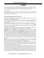
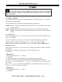
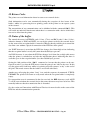
17.12 /$>Paaabbbcccppprrr
The /$>P command is used to change the sensitivity of the sensors for label gap, end paper and end ribbon. This parameter is indeed used by the printer it is disabled the autocalibration. In the contrary case the printing treadle of time in time the more suitable value.
The command must be followed by 5 parameters in the following order:
aaa Sensitivity of transparency sensor (/K1), 3 digits, values from 000 to 255
bbb Not used in ST3xx series (always set to 255). Sensitivity of lateral transparency
sensor in ST4xx, ST5xx series, 3 digits, values from 000 to 255
ccc Always refers to the same sensor in the ST3xx series but can be used to memorise
a different level to function with black mark labels.
In the ST4xx, ST5xx series, relates to the level for the specific black mark reflective sensor 3 digits, values from 000 to 255
ppp End paper sensor. 3 digits, values from 000 a 255 (255 deactivates the sensor)
rrr End ribbon sensor. 3 digits, values from 000 a 255 (255 deactivates the sensor)
The actual significance of these values depends on the specific parameter.
For the label transparency sensors, if the value read is higher than the level memorised in
/$>P….., a gap between one label and another is considered.
The label reflective sensors, consider a gap between the black mark when the value read is
lower than the limit.
Paper and ribbons are considered present when the values read by the respective sensors
are lower than the relative limits.
The ST3xx series only have one sensor whereas the ST4xx, ST5xx series have 3 distinct
sensors:
Lateral transparency sensor- reads from one side of the label K2…..
Central transparency sensor – reads in a more central position of the label K1….
Reflective sensor – reads in a lateral position K3…..
Sensitivity parameters are factory set during the initial quality control and their values can
vary between one printer and another because of the tolerance of the sensors. If the paper
or ribbon is significantly different to that used in the factory, one or more of these parameters may need adjusting.
Series ST3xx and ST4xx, ST5xx printers with a firmware release of 2.0 onwards have an
auto calibration function. In this case the values for the sensors are calculated automatically for every print session. The values memorised in the parameter /$>P are therefore
not used.
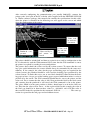
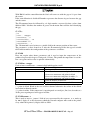
Pre-printed labels with particular shapes or colours can generate misleading values for the
auto calibration function or in the calibration procedure and the values should be calculated manually. This procedure is possible by connecting the ST3xx or ST4xx, ST5xx to a
PC which has a terminal emulation programme. LEPTONS supplies its own TERM.EXE
.
ST3xx ST4xx ST5xx – PROGRAMMING MANUAL - Pag.24
DATAPROCESS EUROPE S.p.A.
After correctly configuring the communication port (usually 9600,8N1), connect the
printer to the serial port of the PC with the cable supplied with the LEPTONS LW-DOS
or WinLw software package (this manual also contains the specifications for this cable)
when the printer is switched on the following text will appear on the screen and which
gives the configuration of the printer.
Value read
by end sensor nastro
Printhead temperature
Value read by label sensor selected
Value read
by end sensor carta
The printer should be witched off and then on again for it to send its configuration to the
PC or alternatively send the /U00 command. Every time that the /U00 command is sent to
the printer it responds by sending its own configuration.
The picture above shows the values read by the various sensors. To ensure that the readings give useful information, the sensors should always be surrounded by the same environment. If, for example, the values for the paper and backing paper are required for the
selected sensor, the printhead should be raised and the backing paper positioned by the
selected sensor. To make this easier, one or two labels should be removed from the backing paper to have a larger area of the backing paper exposed which then makes it easier to
position it by the sensor. The /U00 command should then be sent to the printer and the
value read. Let us assume that the value is 200. Now position the label by the label sensor
and, ensuring that the printhead is still raised, the /U00 command is sent to the printer.
The value, which is in the same position as before, should now be read for the label sensor. This time the value will be lower – in the region of 060. In this example the value of
the label gap should be in between these values i.e. (200-60)/2 +60 =130.This value is
then recorded in the first position for the command /$>P130……………… The same operation is repeated for the end paper and end ribbon sensors.
ST3xx ST4xx ST5xx – PROGRAMMING MANUAL - Pag.25
DATAPROCESS EUROPE S.p.A.
17.13 / $>Tiiihbbbyyyyffffmmmmnnnnttttpppp
The /$>T command is used to set certain parameters regarding the identification of the
printer and the memory configuration. It is advisable to not change this parameter.
If this parameter is changed incorrectly it is possible that the printer will have some difficulties on switch on which can then not be easily resolved.
The command must be followed by 9 parameters in the following order:
iii
h
bbb
yyyy
Printer identification, 3 digits (values from 140 to 406)
Printhead type in reply to status request command , 1 character (recommended:
A for ST403, B for ST406, C for ST302/ST312, 2 for ST314)
Width of bitmap in bytes, 3 digits (values: from 020 to 999, 104 for ST314)
Height of bitmap in dots, 4 digits (values: from 0000 to 9999, depending on
quantity of RAM memory installed on the printer)
ffff
mmmm
nnnn
tttt
pppp
These parameters are normally only set once in the life of the printer – at the factory. They
should not normally be reset unless special situations arise e.g.installation or removal of
memory expansions or if a particular optimisation of the memory is required.
17.14 /*Ax solo ST4xx ST5xx
This command is used to activate or deactivate the applicator.
x=0
x=1
x=2
Applicator not activated
AP403 AP514(normal, variable or fast)
AP406 AP516
17.15 /*Bn
The /*Bn command is used to choose between single or double bitmap configuration.
The command must be followed by the following parameters:
n=0
n=1
single bitmap
double bitmap
The single bitmap is useful when very long labels must be printed and which require a
large amount of memory.
The double bitmap is used when a faster processing speed is required. In this case, half of
the memory is dedicated to the processing of the next label.
ST3xx ST4xx ST5xx – PROGRAMMING MANUAL - Pag.26
DATAPROCESS EUROPE S.p.A.
17.16 /*Dx solo ST4xx ST5xx
This command is used to choose between single or double application with the AP406 applicator.
x=0
x=1
x=2
x=3
Double
Double
Single
Single
application
application
application
application
Left/Right
Right/Left
Left
Right
17.17 /*Txx solo ST4xx ST5xx
The following command sets the delay time before the photo sensors on the applicator
plate are read. The time starts from the moment the label has been printed and is expressed in seconds.
Example: *T01 means that the label has been printed and that the applicator arm has
started its movement and that the photo sensors on the plate will be read after one second.
ST3xx ST4xx ST5xx – PROGRAMMING MANUAL - Pag.27
DATAPROCESS EUROPE S.p.A.
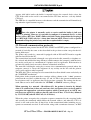
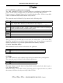
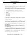
17.18 /*Oo
The /*O command is used to rotate the print in relation to the label and must be followed
by a single parameter which defines the orientation (values: from 0 to 3).
Orientation of 0 maintains compatibility with the ST230, (default value).
The label is printed in reverse if 2 is selected whereas 1 and 3 will rotate the printing by
90° in a clockwise or anticlockwise direction respectively.
Printing direction
0°°
x
y
*
x
90°°
*
y
*
x
y
*
y
180°°
270°°
x
• : 0,0 coordinate
The test label is always printed with a rotation of 0.
17.19 /a – Only for ST4xx ST5xx
The /a command is only used by the ST400 series and is used to configure the output signal for an industrial interface. This is the SYNC signal.
/a0 => Sync with transition from one application cycle and another.
/a1 => Sync without transition from one cycle and another but only at the beginning and
end of the batch of application cycles.
17.20 /Awrc
The /A command is used to configure the attributes of the barcode: thickness of bars,
presence or not of legible characters and the bar guard.
It must be followed by 3 parameters, each of 1 digit, which have the following significance:
w Width of narrow element in dots, equivalent to 1/8 of a mm. (from 1 to 8)
r Ratio between large elements and the narrow ones of the barcode. Only relevant to
Code 39, Interleaved 2/5 and Codabar (values: 1 = ratio 2:1, 2 = ratio 2.5:1, 3 = ratio
3:1)
c Sets presence of characters under barcode or not and the guard bar in accordance
with the following table:
c value
0
1
2
3
4
5
characters
no
no
yes Vexp=1
yes Vexp=1
no
no
guard bar
no
yes
no
yes
no
yes
ST3xx ST4xx ST5xx – PROGRAMMING MANUAL - Pag.28
DATAPROCESS EUROPE S.p.A.
6
7
yes Vexp=2
yes Vexp=2
no
yes
If the characters under the barcode are present, the fonts used for the print depend on the
parameter used for the width of the bars:
w=1 the small font will be used
w=2 or w=3 gives the normal font
w=4, 5, 6, 7 or 8 gives the large font.
The horizontal expansion factor is set to 1 whereas the vertical expansion factor is:
1 for c=2, 3
2 for c=6, 7.
17.21 /Bthhhc..ce
The /B command is used to insert a barcode with its top left hand corner in the position of
the last /E command and in the direction of the last command for /R.
It must be followed by 2 parameters, followed by the string for the barcode and a terminator as in the following example:
t
type of barcode. Only one character. Following values allowed:
0
EAN13
1
EAN8
2
UPC-A
3
CODE39
4
INTERLEAVED 2/5
5
CODABAR
6,7
ADD-ON for EAN/UPC (2 and 5 digits respectively)
A,B,C
CODE128, character sets A, B and C respectively
a,b,c
EAN128, character sets A, B and C respectively
hhh height of barcode expressed in dots, equivalent to 1/8 of mm, three digits (from
008 to 999).
c.. c
sequence of characters of the code, variable length (from 1 to 40 characters)
depending on the barcode type chosen (all valid characters for the type of barcode chosen
are accepted, the first invalid character is interpreted as a terminator)
e
terminator of the sequence. Can be any invalid character for that type of barcode
chosen (normally carriage return except for CODE128/EAN128 A where CR is a valid
character).
The following is a brief description of the rules for the various barcodes available:
Any numerical digit is valid (from 0 to 9). If 12 numbers are input, the
EAN13
check digit will be automatically calculated and placed in the 13th. position. If 13 digits are
input, the checksum will be checked and the barcode will be printed if it corresponds to
the 13th position.
ST3xx ST4xx ST5xx – PROGRAMMING MANUAL - Pag.29
DATAPROCESS EUROPE S.p.A.
EAN8
Same rules as EAN13, but with 7 or 8 digits.
UPCA
Same rules as EAN13, but with 11 or 12 digits.
The valid characters are the 26 CAPITAL letters of the alphabet /from A to
CODE39
Z), the 10 numbers (from 0 to 9), the space and the following special characters - . $ / + %
* @ . The asterisk (*) is used as delimiter of the sequence and must be put at the beginning and at the end. However the code can be printed even if the asterisk is missing. The
symbol (@) is used to indicate the module 43 check-digit and, if required, should be
placed at the end of the sequence immediately before the final delimiter. The maximum
length of the sequence is of 40 characters.
Valid characters are the 10 numerical digits (from 0 to 9). Usually an even
INT.2/5
number of digits (from 2 to 40) can be used. This is due to the structure of the barcode in
that an uneven number of digits will lead to a final checksum digit (calculated under the
ITF rules) being calculated and placed at the end of the barcode. Suitable delimiters are
automatically added to the beginning and the end of the sequence.
CODABAR The numerical digits (from 0 to 9) and the following characters are valid:
ABCD
abcd
tn*e
$+-./:
The first 3 groups of 4 characters are normally used as delimiters and produce the same
effect (A=a=t, B=b=n etc.). The code can be printed without lead/terminator characters.
The last group of 6 characters can be used to include non-numerical information and/or
supplementary data in the sequence. The maximum length is of 40 characters and no
check digit calculation is performed.
This code can only be used in conjunction with EAN-13, EAN-8 or UPC-A
ADD-ON
and is used to extend the number of digits in the barcode with an additional 2 or 5 numbers. The ADD-ON must always be placed to the right of the principal symbol, leaving
sufficient space between them so that the scanner can recognise the combination of the
two. A check digit is automatically added to the barcode but it does not require any space
and is not visible.
This is a more complex code and recognises three different sets of characCODE128
ters. Uses the complete 128 ASCII character set : set A includes ASCII codes from 0 to
95, set B includes ASCII codes from 32 to 127, whilst set C is used for double density
(the resulting dimension is one half of that which would be achieved with SET A or B)
and codes for numerical characters (2 digits are seen as one single character). The maximum length is of 40 characters. Delimiters (start and end) and checksums are automatically added to the barcode as they are an integral part of the structure. The printer also
recognises other special function codes which are not part of the ASCII character set.
These special characters are used to make up a mixed barcode. An example is for a bar-
ST3xx ST4xx ST5xx – PROGRAMMING MANUAL - Pag.30
DATAPROCESS EUROPE S.p.A.
code where numerical and alphabetic characters coexist and where it is possible to assign
to the numerical part a code as in SET C and to the alphabetic characters a code as per
SET A. This maximises the compression of the barcode i.e. it becomes shorter. The following table gives the special characters:
Extended ASCII Function
codes
128
FNC 3
129
FNC 2
130
SHIFT
131
SET C
132
SET B
133
SET A
134
FNC 1
This is a variation of CODE128. It follows the same rules as described
EAN128
above with the difference that it automatically inserts the special character FNC1, immediately after the initiator character. This means that the EAN128 is always a little longer
than the equivalent CODE128.
ST3xx ST4xx ST5xx – PROGRAMMING MANUAL - Pag.31
DATAPROCESS EUROPE S.p.A.
17.22 /C
The /C command is used to empty the buffer of the printer. All the fields are removed and
the parameters are reset to the following default values:
font = normal
source = EPROM (fixed spacing)
horizontal expansion = 1
vertical expansion = 1
interline = 20
pitch = 12
horizontal position of cursor = 0
vertical position of cursor = 14
rotation = 0
mode = 0 (black)
thickness of barcode = 2
ratio of barcode = 2 (2.5 a 1)
barcode string bar guard = 1 (string present, guard bar absent)
The /C command is used before another label is printed.
17.23 /Exxxxyyyy
The /E command is used to position the cursor which will be used as the starting point for
the insertion of any object or bitmap.
It must be followed by 2 parameters, each of 4 digits, with the following significance:
xxxx horizontal position in dots (values: from 0000 to XMAX);
yyyy vertical position in dots (values: from 0000 to YMAX).
The upper limits XMAX and YMAX mentioned above depend on the size of the bitmap
and the current position.
17.24 /Ffhv
The /F command is used to select the font style and the expansion factor.
It must be followed by 3 parameters which identify the desired font and the associated expansion factor in the following way:
f
identification of font, 1 character
from 0 to 6
ST3xx
from0to 6and from A to T ST4xx ST5xx
ST3xx ST4xx ST5xx – PROGRAMMING MANUAL - Pag.32
DATAPROCESS EUROPE S.p.A.
h
v
horizontal expansion factor (values: from 1 to 9);
vertical expansion factor (values: from 1 to 9).
These selections are temporary and are lost when the printer is switched off.
The following table shows the geometrical characteristics of the fonts from 0 to 6 which
are compatible with those available on the ST230 printer (all values are in dots).
GEOMETRICAL CHARACTERISTICS
Font Identifier
0
1
2
3
5
6
Font name
small
normal
big
symbol
magnum mega
Matrix width
8
16
24
32
56
96
Matrix height
9
18
36
32
70
120
Character width
5
10
20
n.a.
39
67
Character height 7
14
28
n.a.
52
72
Default pitch
6
12
24
32
56
96
Default interline
10
20
40
32
70
100
These fonts are resident on the ST3xx and ST4xx printers. The ST4xx series also has the
following fonts :
ID
Font name
interline
A
Arial Bold 4 pts
19
B
Arial Bold 5 pts
24
C
Arial Bold 7 pts
34
D
Arial Bold 8 pts
38
E
Arial Bold 9 pts
45
F
Arial Bold 12 pts
59
G
Arial Bold 16 pts
78
H
Arial Bold 20 pts
96
I
Arial Bold 24 pts
105
J
Arial Bold 32 pts
153
K
Courier Bold 4 pts
20
L
Courier Bold 5 pts
23
M
Courier Bold 7 pts
33
ST3xx ST4xx ST5xx – PROGRAMMING MANUAL - Pag.33
DATAPROCESS EUROPE S.p.A.
N
Courier Bold 8 pts
37
O
Courier Bold 9 pts
43
P
Courier Bold 12 pts
56
Q
Courier Bold 16 pts
76
R
Courier Bold 20 pts
92
S
Courier Bold 24 pts
104
T
Courier Bold 32 pts
150
Note: the expansion factors are assigned to the character independently of the
orientation. There is a limit on the expansion determined by the paper width. The
values from 1 to 8 are recognised correctly whereas 9 is treated as an 8.
17.25 /Gxxxxyyyy
The /G is used to position the origin of the coordinates.
It must be followed by two parameters each of 4 digits with the following significance:
xxxx horizontal position in dots (values: from 0000 to Width);
yyyy vertical position in dots (values: from 0000 to Length).
The maximum values of Width and Length depend on the dimensions of the bitmap (fixed
by the 3rd and 4th parameters of the / $>T command) and the orientation of the label
(fixed by the command / *O).
Note: when this command is executed, the position of the cursor will be the
new origin and the subsequent use of the /E command will refer to that origin.
17.26 /Hnnnn
The /H command is used to control the alignment of the label under the printhead, if the
label sensor is active, otherwise it will control the spacing between prints when continuous paper is used. A value in H which is different to 0 in version 2.0 onwards will deactivate the auto positioning of the label.
With H0000 and the autocalibratione, the label will come set automatically in the point
more correct to maximize the area of print. If you wants correct this location you may act
on the first 4 digit of the /G command.
ST3xx ST4xx ST5xx – PROGRAMMING MANUAL - Pag.34
DATAPROCESS EUROPE S.p.A.
With H0010 and the autocalibration the label will come set with the gap to 10 pass from
the sensor.
If the autocalibration is disabled H number represents the distance in pass between the gap
and the sensor.
The /H command must be followed by a 4 digit number, expressed in dots (values from
0000 to 9999). It defines the number of passes for the motor must still do after identifying
the gap.
17.27 /Iv...
/I0
/I1nv.. vmqqss
/I2ssssnnc.. c
/I3ssssthhhc.. ce
/I4ssssbbbllll
/I5ssssnncc.. c
The /I command is used to insert a variable field in the current position of the cursor.
The parameter v (values: from 0 to 5) after the /I command specifies the type of variable
field and determines the configuration of the parameters as follows:
17.27.1/I0
Does not require other future parameters and is used to input the temperature of the
printhead expressed in degrees Centigrade (Celsius). The printhead temperature is read before every print and its value is updated automatically.
17.27.2/I1nv.. vmqqss
Used to insert a numerator – a numeric field which updates itself.
n
Number of digits in numerator
v
Starting value for numerator in n digits
m
0 increases the numerator and prints in black (°)
1 decreases numerator and prints in black
2 increases numerator and prints in white (^)
3 decreases numerator and prints in white
qq
Value of increase or decrease
ss
Frequency of update i.e. every ss labels
(°): prints in black. Black in the case of direct thermal otherwise the colour of the ribbon
used when in thermal transfer.
(^): prints in white. If the numerator is superimposed on an object (line, box, barcode,etc)
all the parts superimposed will appear in white.
17.27.3/I2ssssnnc.. c
This is used to insert a “remote” field of text, represented by the sequence c.. c, made up
by nn (2 digits, 01 to 99) characters which the external computer must send to the printer
every ssss labels printed (4 digits, 0001 to 9999).
ST3xx ST4xx ST5xx – PROGRAMMING MANUAL - Pag.35
DATAPROCESS EUROPE S.p.A.
Control characters (e.g. CR or CR+LF) can be used as field separators to allow for shorter
text sequences. In this way the printer will complete the string received up to the length of
nn with blank characters.
17.27.4/I3ssssthhhc.. ce
Is used to insert a “remote” barcode sent by an external computer every ssss labels printed
(the other parameters t, h, c, e follow the same rules as the parameter /B).
The text containing the barcode must always be ended with a null character as is normally
done with the command /B.
17.27.5/I4ssssbbbllll
Is used to insert a “remote” graphic field sent by an external computer every ssss labels.
See the instructions for the /Q command for details regarding the parameters bbb e llll.
17.27.6/I5ssssnncc.. c
Is used to insert a date/hour field whose contents must be sent by an external computer
every ssss labels, where nn represents the length of the field (max. 10 characters). cc.. c
has the following structure:
y = year
ex. 95
xx
Y = year xxxx
ex. 1995
m = month [x]x
ex. 1
M = month
ex. 01
xx
O = month in letters in selected language (Command / $>L )
ex. Gen
d = day [x]x
ex. 1
D = day xx
ex. 01
o = day of the week in selected language ( Command / $>L )
ex. Lun
h = hour [x]x
ex. 1
H = hour xx
ex. 01
Io = minutes xx
ex. 23
S = seconds xx
ex. 25
w = number of week [x]x
ex. _1
W = number of week xx
ex. 01
p = number of the day [xx]x
ex. __1
P = number of the day xxx
ex. 001
It is possible to have up to 99 variable fields in a label, mixed in any combination.
If the variable fields designated as “remote” are included in the label, the external computer must send the actual contents of these fields immediately after the print command.
Such fields must be sent in the same order as that in which they have been inserted in the
label.
ST3xx ST4xx ST5xx – PROGRAMMING MANUAL - Pag.36
DATAPROCESS EUROPE S.p.A.
The printer waits for the variable fields from the computer and prints the label only when
all the required characters (or bytes) have been received.
The computer can also send the complete string of the necessary variable data for the
printer for an entire batch of labels. Such data is buffered automatically by the printer and
are recovered as necessary. The computer does not necessarily remain busy for the printer
during the printing of the batch (unless the total quantity of the variable data exceeds the
capacity of the buffer).
Note: in the case of variable text (/I2), when the printer recognises the backspace control character (ASCII code 8), it prints small accented letters and letters
not included in the font with the sequence : accent+BS+letter (this sequence of 3
characters is valid for only 1 character in the field length). This characteristic is for
compatibility with the ST230, but is not otherwise necessary because the new fonts of
the ST314 have a larger international character set with accented letters.
17.27.7/I6nndd..dssssthhhccc...ce
Is used to insert date and time from the printer’s internal clock into a barcode. The command format is as follows:
/I6nndd..dssssthhhccc...ce
Is the length of the string dd...d which describes the format of the date and time
nn
(see command /I5).
dd..d Is the string which describes the format of the date and time (see command /I5).
Is the update frequency for the labels (see command /I3).
ssss
Is the type of barcode (see command /I3 – all are valid except add-on 6 and 7).
t
Warning: the type selected must be consistent with the selected date/hour string
format (example – if the day of the week is to be printed in a literal format, it is
necessary to select a barcode which supports the printing of alphabetic characters
in small print. Also ensure that the maximum length of the string is supported by
the desired barcode).
Is the height of the bars in dots /see command /I3).
hhh
ccc...c Defines the barcode length. Input a string of the same length as the date/hour
string previously defined in dd...d. It is important to insert the correct length because the printer will use this data to clear the area of the barcode before updating
it with the subsequent barcode data (see command /I3).
Sample label :
/*O1/V06
/K0700/H0050/C
/E00000010/M05450450010
ST3xx ST4xx ST5xx – PROGRAMMING MANUAL - Pag.37
DATAPROCESS EUROPE S.p.A.
/E00300060/F211/I5000105H:I:S
/A223
/E00300080/I605HIDMY00010070000000000000Û
/E00300170/I603HIS000110400000000Û
/E00300250/I607*H.I.S*00013040*HH.MM.SS*Û
/E00300310/I607o d O Y0001B040***************Û
/E00300370/I607o d O Y0001b040***************Û
/E02700080/I603HIS00014070000000Û
/E02700170/I603HIS00015040000000Û
/E03300250/I603HIS00019040000000Û
/R1 /E05200080/I603HIS00024070000000Û
/R0 /E00300444/I1300000101
/W0004
17.28 /Jhhss
The /J command is used to set the shape ratio. The most suitable value to obtain a scale
of 1:1 in the X and Y axes is memorised in the default configuration of every printer. This
parameter can be changed for special applications where it is necessary to change the
printing roller or the paper feed settings.
It must be followed by 2 parameters, each of two digits with the following significance:
hh
ss
printhead cycle / period (values: from 01 to 99);
motor feed passes / period (values: from 01 to 99);
The speed of the paper is inversely proportional to the parameter ss. The shape ratio is
determined by the ratio between hh and ss. If the value of these two parameters is correct,
the printing of a square should give exactly the same length sides.
17.29 /Kpdet
The /K command is used to define the operation mode of the printer.
It must be followed by 4 single parameters having the following significance:
p
0
1
2
3
d
0
1
4
5
continuous paper / die-cut labels / black mark (values : from 0 to 3).
ST3xx
ST4xx ST5xx
Continuous paper
Continuous paper
Die cut labels
Lateral transparency photo
not supported
Central transparency photo
Black mark
Reflective photo
label dispenser photo / applicator (values: 0,1,3,4);
ST3xx
ST4xx ST5xx
Synchronism
Polarity
No dispenser
Applicator
Low active
Yes dispenser
Print
Low active
Applicator
High active
Print
High active
ST3xx ST4xx ST5xx – PROGRAMMING MANUAL - Pag.38
DATAPROCESS EUROPE S.p.A.
The “d” parameter in the ST3xx series is used to activate the dispenser. If the dispenser is
active, the next label will not be printed until the printed label has been removed.
In the ST4xx series however, the "d" parameter is used to configure the applicator functions.
Synchronism on the applicator – means that the printer, independently to the package
presence sensor, will print the label which is to be applied. The applicator will collect the
label and advance the plate. The applicator will stop in this position and will wait for the
photo sensor to detect the package. As soon as the photocell detects the package, the applicator will blow the label and take the plate back to its rest position.
Synchronism on print – means that the applicator waits for the package presence sensor
before printing the next label. Only after the package has been detected will the label be
printed and picked up by the applicator and taken to the package where it is applied.
The polarity determines whether the package is considered to have arrived when the
photocell is obstructed (Active High) or when the cell is illuminated (Active Low).
e
dispenser / rewind (values: 0=strip, 1=rewind);
When the dispensing mode has been selected, the values for J are corrected on the printers
that need it to restore the right ratio for the shape. In any case, printers with a firmware
release of 2.0 onwards, having the auto positioning function, will take into consideration
the fact that the label must not stop under the printhead if it is to be picked off manually.
This results in a limited number of millimetres not being available for printing.
t
direct thermal / thermal transfer (values: 0=direct, 1=transfer).
The ribbon presence photo sensor will be deactivated automatically when direct thermal is
selected. All of the printers in the ST3xx and ST4xx series will automatically configure
themselves for direct thermal if they are switched on without a ribbon mounted.
17.30 /Ldlllltt
The /L command is used to design line segments, starting with the current position of the
sensor.
It must be followed by 3 parameters having the following significance:
d
direction in which the segment is to be drawn (values: 0=right, 1=down, 2=left,
3=up);
llll length of the segment in dots (values: from 0008 to the border in the selected direction).
tt
thickness of the segment in dots (values: from 01 to 99).
The direction of this command has priority over the rotation currently selected for printing
(first parameter of the /R command), whereas the colour of the lines drawn depends on the
type of design currently used (second parameter of the command /R): mode 0= colour
black, mode 1= colour white , mode 3= colour opposite to that of the background.
ST3xx ST4xx ST5xx – PROGRAMMING MANUAL - Pag.39
DATAPROCESS EUROPE S.p.A.
Note: the position of the cursor is updated to the opposite corner of the segment
to make it easier for complex drawings in that the cursor does not have to be repositioned every time.
17.31 /Mwwwwhhhhttt
The /M command is used to draw rectangular borders. The top left corner is in the position of the last command /E.
It must be followed by 3 parameters with the following significance:
wwww width in a direction parallel to the printhead (values: from 0008 to the distance
from the border).
hhhh height in the direction of the paper feeding (values: from 0008 to the border).
ttt thickness of the border measured in the direction of the centre (values: from 001
to 999).
17.32 /Nssssoooo
The /N command is used to control the paper cutter which could be installed on the
printer as an optional.
It must be followed by 2 parameters of 4 digits each with the following significance:
ssss number of labels after which it is to cut (values: from 0000 to 9999)
oooo Footstep number of the BackFeed (values: from 0000 to 0200) ST4XX not in
use must be zero.
The positive values for ssss activate the cutter and define the number of labels to print before cutting.
Negative values define the applicator time cycles in the ST4xx series.
In particular:
AP403 AP514
s1= is only used for the sign "-" (minus)
s2= multiplier
s3= time interval between the end of the print and the blowing of the label.
s4= time interval between the label being blown and the printing of the next label.
The factor s2 must be multiplied by s3 and by s4 to obtain the time expressed in tenths
of a second.
E.g.. t3= s2*s3, t4= s2*s4, therefore /N-2440000 and /N-1880000 mean the same thing . in
fact t3= s2*s3=2*4=1*8=8 => 0,8 seconds
AP406 AP516
s1= is only used for the sign "-" (minus)
s2= multiplier
ST3xx ST4xx ST5xx – PROGRAMMING MANUAL - Pag.40
DATAPROCESS EUROPE S.p.A.
s3= time interval between the end of printing and the moment at which the sensors start to
be tested to detect any errors during the run of the piston plate. This time interval should
be regulated to make sure that in the first part of its run, the plate does not signal an error
when it passes close to the support frame of the applicator.
s4= time interval between the complete re-entry of the plate (signalled by a sensor) and the
printing of the next label.
The factor s2 must be multiplied by s3 and by s4 to obtain the time expressed in tenths of
a second.
Values distinct from zero for oooo in the serious ST5xx represent the footstep number
of the BackFeed ( you shouldn't waste bread and the tape returns in after before the print ).
If the autocalibration is abilited and in oooo there is 0000, the BackFeed enables automatically when there is the applicator or the dispenser options.
With the BackFeed all label area is printable also the first millimeters. An other function
of the backfeed is debit more power to the peeloff. In the case of great labels it is not necessary to write also in the first millimeters, but council however to use the BackFeed for
giving more power to the PeelOff. In such case I suggest to use
/N-…0010/H0273/$&%0000100000000000
17.33 /Psss
The /P command has the same function as the command /$>P except that it is easier to
use in this case.
The /$>P command is used to modify the values for the limits of the sensors giving the
values for the new limits to the corresponding sensors. To do this it is necessary to know
which sensor has been selected. With the /P parameter a new value is given for the limits
of the selected sensor.
It must be followed by 3 numbers which represent the limit within which the firmware
will consider the variation for detection (values: from 000 to 255).
This command has the same effect as /$>P, but only influences the currently selected sensor, set by the first parameter of the last edited command /K.
If the auto calibration has not been deactivate in version 2.0 onwards, changing the value
for P will not have any effect because the value for the limit is calculated by the printer.
The transparency photo sensors detect the quantity of infra red light which passes across
the materials whereas the reflective sensors measure the quantity of light reflected by the
materials. High values correspond to a large amount of light in transparency or reflection
of the materials and vice versa.
A reliable detection of the gap means that the difference in signal (the contrast) generated
by the detection of the discontinuity (holes, serrated edges, marks etc.) are significantly
ST3xx ST4xx ST5xx – PROGRAMMING MANUAL - Pag.41
DATAPROCESS EUROPE S.p.A.
greater than the difference in signal (the noise) resulting from the optical discontinuity in
the material – especially if there are pre-printed areas around the sensors.
To have an indication of the transparency / reflective ness of the material, the correct sensor should be chosen and a test label printed with the command /U00. The material
should first be correctly positioned under the sensor.
17.34 /Qbbbllllg.. g
The /Q command is used to download a rectangular graphic bitmap and insert it with its
top left corner in the position of the last command /E.
It must be followed by 2 parameters which define the dimension of the bitmap and by the
binary data which represents its contents as follows:
bbb Number of bytes (groups of 8 adjacent dots) which
make up every single line of the bitmap, three digits
(values: from 001 to 999 or from -01 to -99);
llll number of lines which make up the graphic block, (values: from 0001 to 9999);
g..g data which defines the bitmap.
If the bbb parameter is positive, the data flow will consist of a series of bytes with a total
which is the number of bytes per line multiplied by the number of lines. If the bbb parameter is negative, each byte is replaced by a couple of hexadecimal characters (from 00
to FF) which represent the binary value. Each line is terminated by a sequence of CR+LF.
This alternative alphanumeric format is less efficient than pure binary ( the flow of data is
more than double the length) but is very useful when the external computer cannot manage binary data but only ASCII characters. The flow of bytes is configured as follows:
each bit represents a single dot (1=print, 0=blank), and the most significant bit is on the
left. The bytes of each line are ordered from left to right and from top to bottom.
The block will be automatically truncated if it exceeds the lower margin of the printable
area, depending on the rotation selected.
17.35 /Roc
The /R command is used to set the orientation and the colour of the barcode, lines, borders
and graphics.
It must be followed by 2 single digits with the following significance:
o
c
orientation (values: 0=normal, 1=90° clockwise, 2=180°, 3=270°);
colour in respect to background (values: 0=black, 1=white 2=inverted).
The rotation of parameter o is ignored by the /L command which contains an orientation
parameter.
ST3xx ST4xx ST5xx – PROGRAMMING MANUAL - Pag.42
DATAPROCESS EUROPE S.p.A.
Colour 0 (black) is normally used where black objects must be printed on a white background. Colour 2 (inverted) is used when white articles must be printed on a black background : in this case the background must be created first (the /M command can be used
to design a black box ). Colour 1 (white) is normally used in special cases to design white
lines on a black background thereby avoiding problems which exist at the intersections if
colour 2 is used.
17.36 /Tn
The /T command is used to change between fonts in RAM and EPROM.
It must be followed by a single parameter which can be 0 or 1.
e.g.
E0100100T0F111prova
will write “prova” in position 100,100 with font 1 expansion x=1 y=1. this font is obtained
from the EPROM.
E0100100T1F111prova
will write “prova” in position 100,100 with font 1 expansion x=1 y=1. this font is obtained from the RAM. The fonts in the standard RAM are the so-called proportionately
spaced fonts but these fonts can redesigned or replaced as the need arises.
17.37 /Umm o /Uddffffffff
The /U command is used to recall a "macro". A "macro" is a sequence of commands , for
example a complete label,. The macro can be memorised in a FLASH, however there are
some macros which are memorised by default in the EPROM e.g. macro U00. The macro
U00 is a test label used to verify the configuration of the printer.
It must be followed by 2 characters which, depending on the value, can be followed by 8
characters having the following significance:
mm
dd
f..
f
Macro number, 2 digits (values: from 00 to 99). The
test label is printed with 00 otherwise the corresponding macro allocated in the flash memory (if
present) will be executed.
Identifies the source of the data, 2 characters
(values: A: or B:).
A: refers to the eprom which contains some macros
defined in the factory.
B: refers to the FLASH (optional) for ST3xx series.
C: refers to the FLASH (optional) for ST4xx ST5xx
series.
Refer to the relevant section for a more detailed
explanation of the macros.
Macro name, 8 characters (any DOS file name without
extension) .Obviously only file names which correspond to macros existing in the memory otherwise
nothing will be loaded. If the macro name is less
ST3xx ST4xx ST5xx – PROGRAMMING MANUAL - Pag.43
DATAPROCESS EUROPE S.p.A.
than 8 characters it must be left justified with the
remaining spaces blank.
17.38 /Vssffeppp
The /V command is used to set the parameters which control the printing speed, the paper
feed speed (speed on an unprinted area), and the energy directed to the printhead (printing
intensity).
It must be followed by 4 parameters which have the following significance:
ss
e
print speed in centimetres per second, 2 digits (values: from 02 to max);
optimisation of printhead energy level (values from 2 to 6): represents the number
of active pulses per cycle and is used to regulate the intensity of the black in the printing.
ppp printhead power, 3 digits (values: from 0 to 999).
The print speed is normally set in the range from 50 to 100 mm/s to obtain the best print
quality with standard quality labels and ribbons. Print speeds in excess of 150 mm/sec.
can result in a deterioration of the print quality unless specific materials are used – paper
and ribbons – designed for high-speed printing.
The power level should always be at the minimum value to obtain an acceptable print
quality at the selected speed and with the support materials being used. A lower value will
result in a greyish print with many faded areas whereas a value which is too high can
damage the ribbon and the migration of the pigments on the ribbon can clog the printhead
and also give a messy print. If a correct print cannot be found, it could be that the selected
speed is too high for the quality of the printing materials being used. There are many
qualities of paper and ribbons on the market and your supplier should advise you on the
types and quality to use.
17.39 /Wnnnn
The /W command is used to print the number of labels specified with the 4 digit parameter nnnn, from 0001 to 9999. If the value 0000 is used, the printer will go into an infinite
print loop.
During printing, the printer does not normally process other data but can receive it and
store it in the buffer until this is full (max 64 Kbytes). New data is processed when the
print session is finished and when the printer goes onto ONLINE status.
If the printer has sufficient memory to store 2 complete bitmaps which cover the size of
the desired label, the / *B command can be used to abilitate the processing of the data for
the next label while the previous label is still being printed. This function is particularly
useful when variable data is being printed and this data changes from one label to the next.
This will reduce / eliminate the idle time thereby increasing the throughput of the printer.
A printing session can be suspended by pressing the Pause key and can then be restarted
by pressing the same key. If a print session is to be aborted, the Pause and Feed keys
should be pressed at the same time.
ST3xx ST4xx ST5xx – PROGRAMMING MANUAL - Pag.44
DATAPROCESS EUROPE S.p.A.
17.40 /Xiiippp
The /X command is used to change the “interline” value and it is expressed in number of
dots. The cursor will move down (in relation to the current orientation) with every LF
command. The value of the “spacing” also expressed in number of dots, will move the
cursor to the right (in respect to the selected orientation) every time a new character is designed in the bitmap.
It must be followed by 2 parameters made up of 3 digits with the following significance:
iii interline in dots (values: from -99 to 999);
ppp spacing in dots (values: from -99 to 999).
Interline and spacing are set by default every time a font is selected according to the character dimensions (see the instructions for the /F command). They can be changed with this
command by adding or subtracting the desired number of dots.
The correction of the spacing is correlated to the fixed or proportional spaced fonts.
Note: the values input with this command are automatically multiplied by the
horizontal and vertical expansion factors set with the last font selection command.
17.41 /Yb.. b
The /Y command is used to download a user defined character set which will replace the
default international character set. It also uses the area of the memory designated for the
magnum and mega fonts.
It must be followed by 256 bytes of binary values from 00 to FF hex (from 0 to 255 dec),
defining in this way the correspondence between the printable characters of the ASCII
code and the physical position associated with the dot matrix of the font. The character
map is common to all fonts.
17.42 /Z
The /Z command is used to set the printer back to the configuration stored in the non
volatile memory. This function is performed each time the printer is switched on.
Note: the command is executed automatically every time the printer is switched on.
ST3xx ST4xx ST5xx – PROGRAMMING MANUAL - Pag.45
DATAPROCESS EUROPE S.p.A.
18 Return Codes
The printer can send information about its status to an external device.
Such information can be sent automatically during the reception of data /status of the
buffer), whilst it is processing data or printing (status of the printer) or on request (status
of the sensors).
The transmission of any communication can be inhibited with the command /$&%. This
will avoid any undesired interference when there is a connection with a device which does
not receive data from the printer.
19 Status of the buffer
The control characters ASCII DC1 (code 11 hex, 17 dec) and DC3 (code 13 hex, 19 dec),
otherwise known as XON and XOFF, are sent by the printer to advise the external device
on the status of the reception buffer’s internal 64 Kbytes thereby enabling it to control the
data flow even without a physical connection of the RTS line of the printer.
An XOFF character is sent when the RTS line changes level from high to low indicating
that the reception buffer is nearly full (more than 60,000 bytes present).
An XON character is sent when the RTS line changes level from low to high (this occurs
when the printer is switched on and after the initialisation phase) indicating that there is
available space in the reception buffer (less than 50,000 bytes present).
Setting the 14th position of the / $&% command to 1 means that the printer can be configured in such a way that the RTS moves from the print of one label to the next. In this
way the printer will result busy whilst it is printing and will return to “ready” at the end of
the print. This mode ensures that the buffer is never full with labels.
Another way of keeping the printer “busy” is to send the sequence of commands VT-USUS-NAK. The printer will return to ready mode when the reception buffer is completely
empty.
If a composition error is encountered in the data received, the BEL character (code ASCII
7) will be sent to inform the external device that some characters may have been lost. This
normally indicates that the transmission line is disturbed.
See the section on Connections with External Devices for more details on the status of the
RTS line and the communication protocols.
ST3xx ST4xx ST5xx – PROGRAMMING MANUAL - Pag.46
DATAPROCESS EUROPE S.p.A.
20 Status of the sensors
Every time the control character ASCII ENQ (code 5) is processed, the printer will send a
status communication which is made up by the capital letter "S" followed by 5 consecutive numerical characters and a sequence of CR/LF.
This message informs the external device about the possibility of successfully starting a
print session. The significance of the characters is a follows:
S
p
r
d
c
f
communication header,
status of photo sensor for end paper (0=paper present , 1=end paper),
status of photo sensor for transfer ribbon (0=ribbon present , 1=end ribbon ),
not used ,
not used,
flag indicating the type of printhead installed
0=first switch on
A= 3" printhead
B= 6" printhead
C= 2" printhead
2= 4” printhead
the identification of the printhead (parameter f) depends on the value currently programmed in the second parameter of the command / $>T.
21 Status of the printer
The control characters ASCII DC2 (code 12 hex, 18 dec) and DC4 (code 14 hex, 20 dec)
are sent to the printer every time there is a switch between ONLINE status (even on
switch on) and OFFLINE, indicating whether the printer can or cannot process commands
and characters received from the external computer.
The printer changes between ONLINE and OFFLINE when the operator presses the
Pause key on the front panel and goes OFFLINE when a non recoverable error arises
during a print session.
If the 14th digit of the command /$&% is 1, the printer will send an XOFF and will set itself as busy when it is printing or OFF-LINE. In this case XON and XOFF are sent together with DC2 and DC4 .
The control character ASCII NAK (code 15 hex, 21 dec) is sent by the printer every time
the Command Interpreter processes a command which contains an error (wrong character,
parameters out of range, inexistent macro recalled, etc.).
The control character ASCII SYN (code 16 hex, 22 dec) is sent by the printer every time
the Command Interpreter process the command of a design where a character, line or
graphic block are partially or totally outside of the bitmap.
ST3xx ST4xx ST5xx – PROGRAMMING MANUAL - Pag.47
DATAPROCESS EUROPE S.p.A.
The control character ACK (code 6) is sent every time a print command is processed
(/Wnnnn, control character FF) indicating the start of a print session.
An ACK or a NAK are sent whenever a block of data sent with /$>D is processed (irrespective of whether the checksum is correct or not).
Every time a label is issued, the printer will send a value to indicate the start of the printing, the end and the result of the operation. The communication is a sequence of 6 characters (format Prnnnn) followed by a sequence of CR+LF (8 characters in total), where
the capital letter “P” is sent when the motor starts to move. The rest of the communication
is sent when the print cycle of the single label is complete. If the cutter is installed and has
been activated, the print cycle will include its start up. If the label is not printed for any
reason, the rest of the communication will immediately follow the “P”.
The 4 digits nnnn will send a signal showing the remaining number of labels to print
(from 0000 to 9999), whereas the field represented by r indicates the result of the print
operation with the following significance:
r = 0 The label has been successfully printed and the print session continues normally
unless the label counter has been set to 0000. In this case the print session is terminated (the communication P00000 can be interpreted by the external computer as
the normal completion of the print command).
r = 1 Before printing the label, the end paper photo sensor has detected the absence of
paper and the print session is suspended with the printer going OFFLINE
r = 2 Before printing the label, the photo sensor has detected the end of the ribbon (only
if the printer is operating in thermal transfer mode) and the print session is suspended with the printer going OFFLINE
r = 3 Before printing the label, the printer awaits an external Start signal
r = 4 Not currently used
r = 5 The Pause button has been pressed during the printing indicating that there has been
a manual stop or that the command sequence DLE-US-US-NAK has been received. The print session is suspended when the current label is complete and the
printer goes OFFLINE
r = 6 Before printing the label, the sensor has detected an excessive printhead temperature (above 60°C) and the printer will wait until this temperature drops below the
limit before automatically resuming the print session
r = 7 Before printing the label, the printhead-closed micro switch is opened indicating
that the printhead is not in the correct position for printing. The print session is suspended and the printer goes into OFFLINE
r = 8 After the label has been printed and if the leading edge of the next label is not detected within the predefined length (set by the first parameter of the /$>S command), the motor will stop and the printer will go OFFLINE
r = 9 If the Pause and Feed buttons are pressed together during a print session or if the
command sequence SI-US-US-NAK is received, the print session is terminated
with the end of the current label and without completing the number of labels initially requested. The printer then goes ONLINE.
r = J The AP406 or AP516 applicator is not in the home location before the beginning of
ST3xx ST4xx ST5xx – PROGRAMMING MANUAL - Pag.48
DATAPROCESS EUROPE S.p.A.
the print of the label. Only new firmware relais.
Printing the test label or copies with the FEED key does not generate any communication.
22 MACRO
A “macro”, or a “macro command” consists of a sequence of commands and/or printable
characters which follow the syntax described for the commands received from an external
computer. The macro can be permanently stored in the FLASH memory and can be accessed through the /U command or the front panel.
The printers in the series 400,500 and 300 (currently ST403, ST406, ST514, St516
ST302, ST312, ST314) can have a 512kb Flash mounted where it is possible to store a
maximum of 100 predefined macros (labels). The actual maximum number of labels that
can be stored obviously also depends on the on the size of the labels. The Flash memory is
seen by the printer as a read only diskette. The WinLW programme is used to send the
macro labels into the Flash memory of the printer.
The Macro named “AUTOEXEC”, if present in the Flash memory, is automatically executed when the printer is switched on.
23 Communication Ports
ST3xx:
Serial RS232
ST4xx:
ST5xx:
Serial RS232
Parallel CENTRONICS
Applicator
Industrial interface:
Input
Output
Rewinder
ST3xx ST4xx ST5xx – PROGRAMMING MANUAL - Pag.49
DATAPROCESS EUROPE S.p.A.
Parallel
Centronics
RS232
Applicator
Interface
Interface
winder
re-
Input Photocell
Relè exit
Industrial Interface
23.1 Serial Ports ST3xx ST4xx ST5xx
The printer is equipped with a female 9 pin type “D” connector which is located on the
rear panel and through which it is possible to establish a bi-directional asynchronous
communication with an external device (normally a PC or other compatible equipment).
The connection cable for a PC can be purchased from DATAPROCESS with the Article
code L50500009
The following explains the pin connections for RS232:
1
2
3
4
5
6
7
8
9
Not connected
Input, Reception of Data(RxD)
Output,Transmission of Data(TxD)
Not connected
Massa logica(GND)
Not connected
Output, ready to receive(RTS)
Input, ready to send (CTS)
Not connected
Communication speeds and other parameters can be selected with the /$>B command.
The values are permanently stored in the non-volatile memory. Refer to the command instructions for the communication parameters.
ST3xx ST4xx ST5xx – PROGRAMMING MANUAL - Pag.50
DATAPROCESS EUROPE S.p.A.
23.2 Parallel Port – only for ST4xx ST5xx
This is the female 25 pin type “D” located on the rear panel of the printer. The communication protocol is the standard Centronics and the port is currently only mono direction
(communication with data only on input at the port). The connection cable for a PC is not
a standard cable and can be purchased from DATAPROCESS EUROPE with Article code
L50500010
The following explains the pin connections for the connector:
1
2
3
4
5
6
7
8
9
10
11
12
13
14
15
16
17
18
19
20
21
22
23
24
25
/STROBE
DATA1
DATA2
DATA3
DATA4
DATA5
DATA6
DATA7
DATA8
/ACKNOWLEDGE
BUSY
PAPER EMPTY
SELECT
not connected
+5VDC auxiliary power
not connected
not connected
GROUND
GROUND
GROUND
GROUND
GROUND
GROUND
GROUND
GROUND
23.3 Industrial Interface – only for ST4xx ST5xx
The ST4xx and St5xx series of printers is equipped with an “industrial” interface which
can be used to connect the printers or applicators to an external environment with input
and output signals. The input and output have distinct connectors. The connectors are located on the rear panel and have "D" 9 pin male for the “output” and "D" 9 pin female
for the “input”.
23.3.1 Output (relè) "D" 9 pin male
The signals available for the external devices are READY and SYNC. The signals are
supplied by open or closed contacts.
ST3xx ST4xx ST5xx – PROGRAMMING MANUAL - Pag.51
DATAPROCESS EUROPE S.p.A.
1
2
3
4
5
6
7
8
9
READY - Common1
READY - Normally open1
READY – Normally closed2
READY - Common2
READY – Normally open2
SYNC – Normally closed
SYNC - Common
SYNC – Normally open
READY – Normally closed1
The status normally open and normally closed refers to inactive signals.
The READY signal is active when the printer is in “normal” working conditions i.e. it is
ON-LINE or it is printing. It is inactive when the printer is OFF-LINE or simply switched
off.
The same rules apply for the DTR signal of the serial RS232.
The SYNC signal gives the synchronism for the automatic applicators. The signal is supplied by an external controller to indicate that a print session has started. The signal is activated when the printer is configured as an applicator (/*A1 or /*A2 e N-xxx0000). The
signal is configured through the /a parameter. In particular, if /a0 =>SYNC is active when
an application cycle starts (printing of label and its application) and becomes inactive at
the end of the cycle when the photocell is again ready to detect the presence of a package.
If /a1 => SYNC is active when a print session starts (one or more labels) and becomes inactive at the end of the session (there is no transition between one cycle and the next).
If the external photocell is deactivated i.e. package present, the two modes of operation
become similar. Only if the photocell is in function and there is therefore a time interval
between one cycle and the next will the two configurations be effectively different.
In this case, if only one label is printed /W0001, the signal is active when the printer starts
to print and becomes inactive at the end of the print. If instead a batch of labels is printed
/W0050, there is only one transition of the signal and not at the end of each single label.
23.3.2 Input (optoisolated) "D" 9 pin female
The input signals are used to synchronise the printing of the label with external events e.g.
the removal of a label (dispenser mode) or the arrival of a package which has to have a label applied to it. (applicator photo cell).
The signals can be generated by photocells or simple switches. The following table gives
the connections for either case:
1
2
3
4
5
6
7
8
9
GROUND
Opto1 +
Opto1 Not connected
Not connected
Not connected
Opto2 Opto2 +
+12VDC (500mA max)
ST3xx ST4xx ST5xx – PROGRAMMING MANUAL - Pag.52
DATAPROCESS EUROPE S.p.A.
The switch or the photocell are connected in this way if the signal is to synchronise with
the presence of the package (K1501 N-1990000 in un AP403).
If instead the synchronisation is to be with the removal of the label (K1100 N00010000 in
ST403) it is sufficient to replace in the cable point 2 with 8 and 3 with 7.
23.4 Applicator interface – only for ST4xx ST5xx
This port also has a “D” 9 pin female connector which is also on the rear of the printer.
The following table gives the connections:
1
2
3
4
5
6
7
8
9
GROUND
Input1
Output1
Input2
Output2
Input3
Output3
Input4
+12VDC (500mA max)
23.5 Rewinder interface – only for ST4xx ST5xx
1
Not connected
2
Input synchronism for cutter
3
GROUND
4
Output rewinder motor 14VDC Max 2A
ST3xx ST4xx ST5xx – PROGRAMMING MANUAL - Pag.53