1
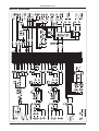
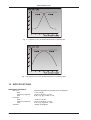
Version 1.1
February 2001
PRO MIXER
www.behringer.com
ENGLISH
DX1000
User’s Manual
PRO MIXER DX1000
SAFETY INSTRUCTIONS
CAUTION:
To reduce the risk of electric shock, do not remove
the cover (or back). No user serviceable parts inside;
refer servicing to qualified personnel.
WARNING: To reduce the risk of fire or electric shock, do not
expose this appliance to rain or moisture.
This symbol, wherever it appears, alerts
you to the presence of uninsulated
dangerous voltage inside the enclosure—voltage that may be sufficient to
constitute a risk of shock.
This symbol, wherever it appears, alerts
you to important operating and
maintenance instructions in the
accompanying literature. Read the
manual.
DETAILED SAFETY INSTRUCTIONS:
All the safety and operation instructions should be read before the appliance is operated.
Retain Instructions:
The safety and operating instructions should be retained for future reference.
Heed Warnings:
All warnings on the appliance and in the operating instructions should be adhered to.
Follow instructions:
All operation and user instructions should be followed.
Water and Moisture:
The appliance should not be used near water (e.g. near a bathtub, washbowl, kitchen sink, laundry tub, in a wet
basement, or near a swimming pool etc.).
Ventilation:
The appliance should be situated so that its location or position does not interfere with its proper ventilaton. For
example, the appliance should not be situated on a bed, sofa rug, or similar surface that may block the
ventilation openings: or placed in a built-in installation, such as a bookcase or cabinet that may impede the
flow of air through the ventilation openings.
Heat:
The appliance should be situated away from heat sources such as radiators, heat registers, stoves, or other
appliance (including amplifiers) that produce heat.
Power Source:
The appliance should be connected to a power supply only of the type described in the operating instructions
or as marked on the appliance.
Grounding or Polarization:
Precautions should be taken so that the grounding or polarization means of an appliance is not defeated.
Power-Cord Protection:
Power supply cords should be routed so that they are not likely to be walked on or pinched by items placed
upon or against them, paying particular attention to cords and plugs, convenience receptacles and the point
where they exit from the appliance.
Cleaning:
The appliance should be cleaned only as recommended by the manufacturer.
Non-use Periods:
The power cord of the appliance should be unplugged from the outlet when left unused for a long period of time.
Object and Liquid Entry:
Care should be taken so that objects do not fall and liquids are not spilled into the enclosure through openings.
Damage Requiring Service:
The appliance should be serviced by qualified service personnel when:
- The power supply cord or the plug has been damaged; or
- Objects have fallen, or liquid has been spilled into the appliance; or
- The appliance has been exposed to rain; or
- The appliance does not appear to operate normally or exhibits a marked change in performance; or
- The appliance has been dropped, or the enclosure damaged.
Servicing:
The user should not attempt to service the appliance beyond that is described in the Operating Instructions. All
other servicing should be referred to qualifield service personnel.
2
PRO MIXER DX1000
FOREWORD
Dear Customer,
Welcome to the team of PRO MIXER users and thank you very much for expressing your confidence in
BEHRINGER products by purchasing this unit.
It is one of my most pleasant tasks to write this letter to you, because it is the culmination of many months of
hard work delivered by our engineering team to reach a very ambitious goal: presenting an outstanding mixer
for flexible use in studios, clubs or at home. The task to develop our new PRO MIXER series certainly meant
a great deal of responsibility, which we assumed by focusing on you, the discerning user and musician. It also
meant a lot of work and night shifts to accomplish this goal. But it was fun, too. Developing a product usually
brings a lot of people together, and what a great feeling it is when everybody who participated in such a project
can be proud of what we’ve achieved.
It is our philosophy to share our joy with you, because you are the most important member of the BEHRINGER
family. With your highly competent suggestions for new products you’ve greatly contributed to shaping our
company and making it successful. In return, we guarantee you uncompromising quality (manufactured under
ISO9000 certified management system) as well as excellent technical and audio properties at an extremely
favorable price. All of this will enable you to fully unfold your creativity without being hampered by budget
constraints.
We are often asked how we can make it to produce such high-grade devices at such unbelievably low prices.
The answer is quite simple: it’s you, our customers! Many satisfied customers means large sales volumes
enabling us to get better conditions of purchase for components, etc. Isn’t it only fair to pass this benefit back
to you? Because we know that your success is our success, too!
I would like to thank all people whose help on “Project DX1000“ has made it all possible. Everybody has made
very personal contributions, starting from the designers of the unit via the many staff members in our company
to you, the user of BEHRINGER products.
My friends, it’s been worth the trouble!
Thank you very much,
Uli Behringer
3
PRO MIXER DX1000
BLOCK DIAGRAM
4
PRO MIXER DX1000
PRO MIXER
Professional DJ mixer with a total of 10 stereo sources on 5 dual-input channels
DX1000
s Two professional high-class microphone channels with peak indicator and effects send facility
s High-precision phono preamps for bass power and crystal clean sound
s Ultra-musical 3-band EQ with independent defeat switch on all channels
s Kill switch attenuates the bass for more creativity
s Ultra low-noise design comparable to studio-grade consoles
s Replaceable and high-quality crossfader
s Fully adjustable talkover function automatically attenuates the main output
s PFL switches on all channels with two different PFL modes
s Balance control allows you to blend between main and PFL on the phones section
s Extremely flexible, intuitive X-Y routing with status control LEDs on each channel
s Large X-Y punch and cut buttons at the crossfader for super effects such creative mixing!
s Main mute (-20 dB) and main boost buttons (+4 dB) for unlimited creativity
s Balanced main outputs on gold-plated XLR, 1/4" TRS and RCA connectors
s Additional adjustable zone output allows you to control the level of a second area or room
s Subwoofer output with adjustable x-over frequency and level control for separate bass amplification
s Remote-start buttons to start your turntables and CD players etc.
s Separate tape outputs with and without microphone signal
s BNC socket with dimmer control for 12 V gooseneck lamp (not included)
s High-quality 100-mm channel faders like those foun in professional recording consoles
s Super-rugged construction ensures long life, even under the most demanding conditions
s Manufactured under the ISO9000 certified management system
5
PRO MIXER DX1000
TABLE OF CONTENTS
1. THE MANUAL ........................................................................................................................ 7
1.1 Nomenclature .................................................................................................................................. 7
2. PRO MIXER OVERVIEW ....................................................................................................... 7
2.1
2.2
2.3
2.4
2.5
2.6
Highly accurate main and PFL peak—reading bargraph meters ....................................................... 8
How will You use your DX1000? ...................................................................................................... 8
PSU (Power Supply Unit) ................................................................................................................ 8
Rack mounting the DX1000 ............................................................................................................. 8
Warranty ......................................................................................................................................... 8
Packing .......................................................................................................................................... 8
3. MONO INPUT CHANNEL ..................................................................................................... 9
3.1 Input selection ................................................................................................................................ 9
3.2 Gain setting .................................................................................................................................... 9
3.2.1 Quick way............................................................................................................................. 9
3.2.2 Gain setting by using PFL .................................................................................................... 9
3.3 Insert point ...................................................................................................................................... 9
3.4 Equalizer....................................................................................................................................... 10
3.5 Output........................................................................................................................................... 10
3.6 Effects .......................................................................................................................................... 10
4. STEREO INPUT CHANNEL ................................................................................................ 10
4.1 Input selection .............................................................................................................................. 10
4.2 Gain setting ................................................................................................................................... 11
4.2.1 Quick way............................................................................................................................ 11
4.2.2 Gain setting by using PFL ................................................................................................... 11
4.3 Equalizer....................................................................................................................................... 12
4.4 Output........................................................................................................................................... 12
5. TALK OVER ......................................................................................................................... 12
6. MASTER AUDIO OUTPUTS ............................................................................................... 13
6.1
6.2
6.3
6.4
6.5
6.6
Crossfader ....................................................................................................................................
Transforming with punch and cut ...................................................................................................
Main/tape outputs .........................................................................................................................
Main boost and main mute ............................................................................................................
Zone .............................................................................................................................................
Effect return ..................................................................................................................................
13
13
14
14
14
14
7. HEADPHONES, MONITORS & PFL .................................................................................. 15
7.1 Monitoring ..................................................................................................................................... 15
7.2 Headphones—read carefully—this is tricky! .................................................................................. 15
7.3 Permanent PFL—using PFL as a listening subgroup .................................................................... 15
8. SUB BASS ........................................................................................................................... 16
9. CONTROLLING EXTERNAL DEVICES ............................................................................. 16
9.1 Desk lamp .................................................................................................................................... 16
9.2 Remote control of audio devices .................................................................................................... 16
9.3 Sound-to-light ................................................................................................................................ 16
10. CONNECTIONS .................................................................................................................. 17
10.1 PRO MIXER DX1000 connections ................................................................................................. 17
10.2 Plug soldering guide ...................................................................................................................... 17
11. CROSSFADER ADJUSTMENT .......................................................................................... 19
11.1 Overlap ......................................................................................................................................... 19
11.2 Slope ............................................................................................................................................ 19
12. SPECIFICATIONS ................................................................................................................ 20
13. WARRANTY .......................................................................................................................... 22
6
PRO MIXER DX1000
1. THE MANUAL
We know that reading manuals can be a bore, and that you are probably impatient to get started with your new
DX1000 mixer, if you haven’t already! It is true that with a modicum of knowledge about audio equipment you
could get up and running successfully, but chances are you will not be able to exploit the full potential of your
DX1000 (or yourself) until you have some of its more advanced features explained. Please, please at least read
through all the text in this section, which contains important safety tips to help preserve you and your valuable
equipment.
+
You’ll get nowhere with your DX1000 unless it is properly connected to your music sources,
power amplifiers, tape recorder etc. We strongly advise that you never use cheap connecting
plugs for audio—use only gold-plated ones, as these are best at resisting corrosion. Run any
mics on balanced lines to minimize unwanted interference, and check those mains plugs for
loose cable clamps or electrical contacts frequently.
Good quality plugs are extremely important, all the more so where connections are left untouched for long
periods. (Unplugging leads frequently can help to keep contacts clean by mechanical abrasion). Also moisture
in a humid nightclub greatly accelerates the build-up of oxide (e.g. rust) on metal contacts. For the complete
wiring scheme for all inputs and outputs please refer to chapter 10 “CONNECTIONS”.
+
+
Never patch line level devices into your highly sensitive phono inputs. Phono cartridge output
is measured in millivolts. CD and tape players are of the order of magnitude of a volt. With line
levels you are looking at signals 100 times more powerful than a phono pre-amplifier is
designed to handle!
Please always ensure that the mixer power supply is securely connected to the mixer before
you turn on the mains supply. Power amps should always be turned on last of all in order to
minimize switch-on thumps, which can easily damage loudspeakers. Check that there is no
signal going through the DX1000 when the amps are switched on in order to avoid any sudden
volume surges. It is best to turn down all output faders and rotary controls first.
1.1 Nomenclature
This manual is a combination of figures and text. Together these precisely define and describe all the functions
of your DX1000. For reasons of clarity you might find certain text or subject matter appears more than once in
the manual. This means we pay a little more in printing and publishing costs, but it does mean that each
section is self-contained and therefore easier for you to read.
Sometimes technical information is provided in brackets. Don’t worry—you don’t need to know what the figures
mean in order to have success with your DX1000. This info is included for the benefit of sound engineers, not
DJ’s! The manual is also crammed full of creative ideas on how to play your DX1000 to full advantage. Try to
read it from cover to cover at least once. Otherwise you’ll never know what possibilities you might be missing
out on!
+
The following operational manual will introduce you to the BEHRINGER PRO MIXER DX1000
and its various functions. After reading the manual carefully, make sure it is always on hand
for future reference.
2. PRO MIXER OVERVIEW
The DX1000 is a multi-functional stereo mixer designed for all applications where pre-recorded music is mixed
and played. It is equally at home, in dance clubs, personal DJ setups and broadcast studios. It has two mono
mic channels and five stereo music channels. The mic channels may be routed to the main mix directly. Music
channels, on the other hand, must be assigned to one of two stereo submixes, called X and Y. A super-smooth
user-definable VCA crossfader ultimately controls the blend of X and Y being sent to the main mix.
1. THE MANUAL
7
PRO MIXER DX1000
2.1 Highly accurate main and PFL peak—reading bargraph meters
The main output level is constantly monitored by a pair of highly accurate main bargraph meters
. In
addition, all channels have PFL (Pre-Fader-Listen)
. This means that you can see (on a separate PFL
bargraph meter) and hear (on your headphones and/or monitors) the music you are about to play without
disturbing the mix—essential if you want to come in at the same level and in time with the music currently
playing. All professional DJ’s strive to do this, often overlapping two tracks, or slowly cross fading between
them. (These and other DJ mixing tricks will be explained elsewhere in this manual.)
2.2 How will you use your DX1000?
Your DX1000 is a creative instrument. Learn to play it well. If possible, experiment with it “off-line”—before you
use it in earnest in a club or studio. It offers you many creative music mixing possibilities, with its ultra
DJ-friendly control surface. In addition many special features have been included to enhance the flexibility and
ease of operation of your mix. For example, the adjustable TALK OVER feature can automatically and
temporarily reduce the music level while you are speaking. We have given particular attention to metering your
music with PFL offered on every channel. In addition all channels have signal present and overload LEDs constantly monitoring input levels. You will also see virtually every switch on your DX1000 has an associated status
LED, to let you know when it is engaged. Just another way in which we try to make life easier for you, the DJ.
It is true that not all the features of the DX1000 are relevant to every application. For example the REMOTE
(machine control) buttons may be extraneous to the needs of the vinyl DJ, while the EQ KILL switches might
never be used in a hospital radio installation. Nonetheless the superior quality of all of the features of your
DX1000 means you will never find it wanting, which ever way you use it.
2.3 PSU (Power Supply Unit)
Any amplifier circuit is limited in its transient response by the available current. Every mixer has numerous line level
operational amplifiers (op-amps) inside. When being driven hard, many desks begin to show signs of stress due to
power supply limitations. Not so with the PRO MIXER DX1000. The sound will always stay clean and crisp right up
to the operating limits of the op-amps themselves, thanks to our generous 50 W external power supply unit.
Please connect the PSU with the PRO MIXER DX1000 PSU connector
+
on the rear panel of your mixer.
Do not connect the PSU to the PRO MIXER while the PSU is connected to the mains supply.
Connect switched-off desk and PSU first before you connect the PSU to the mains supply.
2.4 Rack mounting the DX1000
Your DX1000 is shipped with fixed rack ears. If you want to make your DX1000 a desktop mixer, loosen the
screws from the side panels and remove the fixed rack ears (note, that there is a left and a right one).
2.5 Warranty
Please take time to have the warranty card filled out completely by your specialized dealer and return it within
14 days after the date of purchase, so as to be entitled to benefit from our extended warranty. You will find the
serial number
of your DX1000 on the rear panel. Or use our online registration option available on the
Internet at www.behringer.com.
2.6 Packing
Your BEHRINGER PRO MIXER DX1000 was carefully packed in the factory and the packaging was designed
to protect the unit from rough handling. Nevertheless, we recommend that you carefully examine the packaging
and its contents for any signs of physical damage, which may have occurred in transit.
+
8
If the unit is damaged, please do not return it to us, but notify your dealer and the shipping
company immediately, otherwise claims for damage or replacement may not be granted.
Shipping claims must be made by the consignee.
2. PRO MIXER OVERVIEW
PRO MIXER DX1000
3. MONO INPUT CHANNEL
Plug a mic or line source (tape, CD player etc.) into the appropriate MIC
music at typical volume to check out and set up the channel.
+
or LINE
input. Speak or play
The mic pre-amps are of the same quality as those in our award-winning EURODESK studio
consoles. These give an incredibly warm, clear and noiseless performance. Mic and line inputs are on balanced XLR and 1/4" jacks respectively. Balanced operation gives best noise
performance. Unbalanced microphones need to have XLR pins 1 and 3 shorted. Any Line
source will work perfectly well if a mono jack is used, or the ring and barrel of a TRS jack are
shorted (see chapter 10 “CONNECTIONS”).
3.1 Input selection
Inputs are on the back panel. Your input source is selectable between MIC and LINE by a switch
of associated LEDs
lets you know which input is selected.
. A pair
3.2 Gain setting
+
Gain is dependent on EQ. Set up your EQ before fine-tuning gain. If you re-EQ, also re-check
gain.
3.2.1 Quick way
. As long as the SIG. LED is flickering and
Channel input level is continuously monitored by a pair of LEDs
the PEAK one isn’t the gain is reasonable. Mic channel input level can be continuously adjusted by the GAIN
knob
(from +10 to +60 dB; Mic signals are low, therefore they need to be heavily pre-amplified).
PEAK lets you know if you overload the channel (it lights at +18 dB).
+
+
SIG. lets you know if a signal is present (it only responds to bass frequencies). That’s why you
can use it to keep an eye on the beats.
If you are using a mono line source in a mic channel, the gain structure is comparable to that
on a stereo music channel, albeit 20 dB more sensitive. (from - 10 to + 40 dB ; = 20 dB pad on
mic input)
3.2.2 Gain setting by using PFL
Pre-Fader-Listen is the professional way to set gain. Hit the PFL button
to temporarily send the channel
signal to the PFL bargraph meter
. Adjust the GAIN control until the bargraph meters are in the yellow
(0 dB) but not the red (Clip). Once gain has been set for a channel, release its PFL button.
+
You will usually want to PFL only one channel at a time, otherwise the PFL meter reading will
be meaningless.
3.3 Insert point
Situated on the rear of the console, mic channels have insert points
on TRS jacks. (These are post-gain
and pre-EQ). You can use these combined input/output sockets to put a compressor, gate or any other signal
processor(s) in line with your microphone (see chapter 10 “CONNECTIONS”).
+
Compressors can help even out voice volume, adding loads of energy, but they can also cause
feedback problems if over-used. Noise gates shut off mics automatically when not in use—
useful for keeping out music spillage which can muddy the sound of your mix. Often a
compressor/gate combination is best. Check out the excellent BEHRINGER range of
interactive dynamics products.
3. MONO INPUT CHANNEL
9
PRO MIXER DX1000
3.4 Equalizer
The mic channel EQ section comprises three control knobs and one switch. Depressing the LOW CUT
switch
rolls off the bass end (-18 dB/oct @ 75 Hz). We recommend using this feature with microphones to
eliminate “popping” and handling noise. Where loud music is playing, LOW CUT also helps to avoid bass
feedback. Separate controls cut and boost TREBLE
, MID
and BASS
frequencies respectively.
Use EQ creatively to sweeten the sound of your microphone, or defensively to help cut feedback (see below for
EQ specifications).
EQ
Frequency
Range
Centre
Shelving EQ
10 kHz
+/- 12 dB
OFF
Mid
Peaking EQ
750 Hz
+/- 9 dB
OFF
Bass
Shelving EQ
50 Hz
+/- 12 dB
OFF
Treble
Tab. 3.1: Equalizer of the mono input channels
+
If you are serious about your mic channel, and want to really kill feedback, you can patch our
FEEDBACK DESTROYER PRO DSP1124P across the channel insert point at the rear of the
console. It is ideal for this purpose.
3.5 Output
Mic channel output is fed directly into the main mix, not via the X and Y subgroup channels. Level is controlled
by a precision 100 mm fader
, while stereo position is set by the PAN control
. The channel signal is
sent to the mix by depressing the CHANNEL ON switch
. A LED indicator illuminates when the channel is
on. (Channel on is the inverse of the more traditional channel mute found on standard recording consoles).
+
+
The mic channels are routed to the tape outputs
on the rear panel of the DX1000, but not
to the tape outs
situated to the left of the main meters, marked “WITHOUT VOICE”.
The faders used are special high-quality true-log faders. These give ultra-smooth operation
even at low levels, on a par with those used in very expensive studio consoles.
3.6 Effects
You can patch a mono or stereo outboard effects processor into your DX1000 via the effect send
and return
jacks on the back panel. Now you can effect your voice instantly simply by punching the illuminated
EFFECT button
. The effect send level is dependent on the fader setting. Adjust the desired amount of
effect (from -oo to +30 dB) by the EFFECT RETURN knob
to the right of the bargraph meters.
+
Set your effects unit input level so that the input meter reading (if there is one) is healthy when
you are sending a typical signal to it. Too low a level will mean too much hiss on your effects
return, too high and you’ll get distortion.
4. STEREO INPUT CHANNEL
Plug a phono (turntable) or line source (CD player etc.) into the appropriate PHONO
music at a typical volume to check out and set up the channel.
or CD
input. Play
4.1 Input selection
Inputs are on the DX1000’s back panel. Your input source is selectable between a pair of stereo inputs by the
switch
at the top of the channel strip. An associated pair of LEDs
lets you know which input is selected.
The choice of inputs depends on which of channels 3 - 7 you are looking at. The mixer is set up as follows:
10
4. STEREO INPUT CHANNEL
PRO MIXER DX1000
Channel
Input 1
Input 2
3
PHONO 1
CD 1
4
PHONO 2
CD 2
5
PHONO 3
CD 3
6
LINE 1
CD 4
7
LINE 2
TAPE*
Tab. 4.1: Stereo channel configuration
* Channel 7’s TAPE input
+
+
+
is parallel-wired to the TAPE IN
on the top panel.
Never patch line level devices into your highly sensitive phono inputs. Phono cartridge output
is measured in millivolts. Line level signals are of the order of magnitude of a volt. With line
levels you are looking at a signal up to 100 times more powerful than the phono pre-amplifier
is designed to handle!
If for some reason your turntable has a built-in RIAA pre-amp, you should patch it into a line
level input.
A mix could include three turntables (channels 3 - 5) and two samplers for creative DJ work, or
four CD/cart players plus a stereo tape recorder for a broadcast studio. In fact any line level
signal could be patched into any line-level input, so channel 7 could return an extra CD player,
for example. Only the phono inputs are device-specific, being matched exactly to your
cartridge response.
4.2 Gain setting
+
Gain is dependent on EQ. Set up your EQ before fine-tuning gain.
4.2.1 Quick way
Channel input level is continuously monitored by a pair of LEDs
. PEAK lets you know if you’re about to
overload the channel (it lights at +18 dB). The SIG. LED only responds to bass frequencies and is perfectly
suited to keep an eye on the beats. As long as the signal LED is flashing on the beat (and the peak one isn’t)
you can be sure the gain is reasonable. Do this for all music channels. Channel gain can be continuously
adjusted by the GAIN knob
(from -20 to +20 dB).
+
If you are in the habit of slamming the channel faders all the way up (+6 dB), try to keep your
MAIN faders at a compensatory -6 dB to make sure you don’t risk distortion. At this level PFL
and MAIN meters should show the same level (check this by engaging PFL on the channel
currently playing), allowing easy comparison between outgoing (playing) and incoming (cueing)
tracks. Keep an eye on the output meters—red spells trouble. Remember—distortion is not
volume, and any distortion introduced before the power amplifiers and speakers will worsen
your sound and cause amps and speakers to clip sooner.
4.2.2 Gain setting by using PFL
Pre-Fader-Listen is the professional way to set gain, and we always recommend you do it if you have the time.
Hit the PFL button
to temporarily send the channel signal to the PFL meter
. Adjust GAIN until the
PFL meter is hitting the yellow (up to +10 dB) but not the red (clip). Once gain has been set for a channel,
release its PFL button.
+
Normally you will want to PFL only one channel at a time. This might not be true if you are
layering tracks, and/or using “Permanent PFL”—see the chapter 7 “HEADPHONES, MONITORS
& PFL”. Also note that the mono PFL meter is a sum of L and R channel signals.
4. STEREO INPUT CHANNEL
11
PRO MIXER DX1000
4.3 Equalizer
The channel EQ section comprises three control knobs and two switches. The EQ ON
switch activates
the tone controls which enable cut and boost of TREBLE
, MID
and BASS
frequencies
respectively (see below for specs.) EQ can sweeten or effect a track, with the fading out and in of frequency
bands being very popular. When you press the KILL switch
the bass EQ is set to maximum attenuation
independent of the setting of the bass EQ control.
EQ
Frequency
Range
Centre
Shelving EQ
10 kHz
+/- 12 dB
OFF
Mid
Peaking EQ
750 Hz
+/- 9 dB
OFF
Bass
Shelving EQ
50 Hz
+/- 12 dB
OFF
Treble
Tab. 4.2: Equalizer of the stereo channels
+
EQ is particularly useful if two or more music tracks are playing together, as frequencies often
clash. Low frequencies in particular can phase and cancel, causing uneven bottom-end
response. The trick is to cut the bass from all but one track playing. You can roll off the bass by
turning BASS fully anti-clockwise.
4.4 Output
Channel level is controlled by a precision stereo 100-mm fader
+
.
The faders used are high-quality true-log faders. These give ultra-smooth operation even at
low levels, on a par with those used in the most expensive studio consoles.
You wont hear anything in the main mix unless the channel is switched on by depressing the CROSSFADER
switch
. This sends the channel signal to either of two stereo submixes, which we call X and Y. The
ASSIGN button
selects between these two submixes, and a pair of LEDs
clearly show you which of
X or Y is currently selected per channel. The X and Y mixes are then routed to opposite ends of the main
crossfader
.
+
You can immediately tell if any channel is switched on (CROSSFADER switch depressed) by
looking at the master ASSIGN X and ASSIGN Y
indicators situated under the crossfader.
5. TALK OVER
Let’s say you are talking over a music intro. You would almost certainly want to attenuate the music while you
speak. The DX1000 talk over system does this for you—automatically. Depressing the TALK OVER button
on a mic channel engages the talk over system. You can leave this button down all the time—it will not
affect the music unless you speak into the mic, provided you set the system up correctly. How do you do this?
If you look to the left of the main bargraph meters you will see three rotary controls and two LEDs. These are
the master talk over adjustments you will want to make. Once you have set them up for your system you will
probably not have to alter them unless something else is changed.
SENSITIVITY
sets the speech level threshold at which attenuation (also called gain reduction) kicks in
once talk over is activated by a mic channel signal.
TIME
controls the rate at which music volume recovers after a mic channel signal has activated the
automatic music level reduction process.
DAMPING
allows you to adjust the depth of music attenuation triggered by the mic channel signal.
To set up these controls properly, first turn DAMPING full on (MAX). Set up the gain on your mic channel using
PFL. Now adjust SENSITIVITY until the music is always attenuated by a voice signal. (Attenuation is at MAX
to enable you to hear this adjustment as clearly as possible.)
12
5. TALK OVER
PRO MIXER DX1000
+
Take care to ensure that SENSITIVITY is not set too high, otherwise spill from loudspeakers
into the mic could trigger the talk over system, and the music volume will just keep going up
and down! (You have set up an intermittent negative feedback loop.)
Once SENSITIVITY has been set so that talk over is only being activated by speech, it’s time to fine-tune the
system with the other two controls again, according to taste. Twin LEDs let you know how your talk over
is lit, your music is being automatically attenuated. ON
lets you
system is behaving. When DAMP
know that one or both mic channels have talk over engaged.
+
+
If two mics are being used, set SENSITIVITY with both mic channels switched on.
Talk over could just as easily be used for MC-ing. It might not however be appropriate for
rapping, which takes place alongside rather than over the music, unless the damping effect is
set to be quite subtle.
6. MASTER AUDIO OUTPUTS
6.1 Crossfader
The heart of your music mix is the horizontally-mounted ULTRA-HIGH QUALITY FADER
, which controls
the blend of the X and Y mixing channels. When set fully to the left, only X is heard in the mix, and vice versa.
We know how much you rely on this, and for that reason we have not only ensured that it is incredibly durable
and smooth-acting. We also allow you to tailor its response to your “feel” by means of a simple adjustment
(see chapter 11 “CROSSFADER ADJUSTMENT”). The crossfader is most often used to fade one track into
another during a DJ mix.
+
+
+
If you are bringing in an intro over an outro, there will be a time when you want to hear both
tracks at full volume. Simply pause your crossfader in the middle position until you are ready
to fade out the outgoing track.
The crossfader is actually a sophisticated VCA controller. Its ultra-high quality design means
that you can expect a massive 200,000 smooth operations before wear & tear even becomes a
factor. And even if the fader does get something nasty poured over it by mistake (please don’t
do this!) the quality of your music should be unaffected. This is because no audio signal
actually passes through your crossfader, unlike on many other DJ mixers.
You can immediately tell if any channel is switched on (CROSSFADER switch depressed) by
looking at the master ASSIGN X and ASSIGN Y indicators
situated under the crossfader.
6.2 Transforming with punch and cut
Transforming is a DJ term used to describe the chopping up of sound to create dramatic effects. Traditionally
this is done by rapidly moving a crossfader to give a stuttering or “gated” effect, either between two music
sources, or one source and silence. Another DJ trick is to use the channel faders or channel on buttons to
chop one music track over another. These methods are still valid, but if you are looking for instantaneous
transforming action, check out our ergonomic alternative—a pair of big assignable PUNCH/CUT buttons. We
are sure you will grow to love their speed and ease of operation.
Punch and cut are two transform modes selectable by the TRANSFORM MODE button
. A pair of LEDs
lets you know whether PUNCH or CUT is active. The X and Y PUNCH/CUT buttons
and
are
ergonomically situated by the crossfader with which they are designed to work. CUT mode enables the big
buttons to be used as mutes for interesting gating effects, temporarily silencing the X or Y output. In PUNCH
mode the X button
introduces the X signal to the mix, while the Y button
brings in the Y signal. This
means you can add in bits and beats from X on top of Y and vice versa, opening up your scope for creative
mixing.
6. MASTER AUDIO OUTPUTS
13
PRO MIXER DX1000
+
+
+
+
This is the first time we have come across any really BIG buttons on the DX1000. At this point
it’s worth pointing out that all the smaller switches on your DX1000 are latching. This means
they stay down until you hit them again. Big buttons are all non-latching, or momentary in
operation. This means that they are only active when your finger (or other appendage) is
actually holding them down, like the keys on a MIDI keyboard. These are ideal for executing
transformations, as you will very quickly find as you get into using your DX1000.
Try running a rhythm track through X (crossfader fully to the left). Now use the Y button in
PUNCH transform mode to manually chop in a sustained signal like orchestral music, ambient
sounds, noise, whatever.
As well as using the X - Y crossfader to select / fade between X and Y you can also use it to
blend X and Y together, by simply leaving it somewhere in the middle. Now you can use the
big buttons in CUT mode to chop between X and Y for more creative music gating effects.
You can send more than one channel to either X, Y or both. In practice you will usually only
send one at a time, but if you are layering tracks you might want to send more. Also you can
crossfader between channels assigned to the same side of the crossfader using the 100 mm
channel faders.
6.3 Main/tape outputs
Level to the main outputs (Max. output +28 dBu balanced, +22 dBu unbalanced) is ultimately governed by a
pair of precision 60 mm main faders
. This level is continuously monitored by the pair of highly accurate
tri-colored bargraph meters
sited immediately above the output faders. The main outputs constitute a
blend of X, Y and the two mic channels, all covered previously in the manual, plus the stereo effects return. The
main output also feeds the tape outputs on the back of the console.
+
+
The tape outputs on the top of the console are taken directly from the output of the crossfader.
This mix does not include the mic channels 1 and 2.
Never connect to both sets of tape inputs/outputs (see chapter 10 “CONNECTIONS”).
6.4 Main boost and main mute
MAIN BOOST
and MAIN MUTE
are big non-latching buttons acting on the main outputs, temporarily
boosting (by +4 dB) and cutting (by -20 dB) volume.
+
+
Main cut could be used for audience sing-along bits. Or you could use main boost to
emphasize the beats etc.
Main boost should not be applied for more than just spot effects, as you will probably stress the
sound system, or simply cause the limiters to come in harder.
6.5 Zone
The ZONE stereo output
is a second main mix output with its own totally independent ZONE LEVEL
control
. This can be used for feeding the mix into a separate sound system such as DJ foldback, or
another room or area in a dance club.
6.6 Effect return
A line-level stereo effect return
(Max. gain 30 dB) feeds directly into the mix, level being adjusted by the
EFFECT RETURN knob
. This input is designed to accept the output from a mono or stereo effects unit
(see chapter 10 “CONNECTIONS”). It could also be used to return another stereo music source such as DAT
or mini disc if five stereo channels are not enough for your music needs.
14
6. MASTER AUDIO OUTPUTS
PRO MIXER DX1000
7. HEADPHONES, MONITORS & PFL
7.1 Monitoring
A separate stereo MONITOR output
is provided. Level is controlled by a single 60 mm MONITOR stereo
fader
. The monitor signal is taken directly from the main mix. Engaging PFL anywhere on the board
changes the monitor source to PFL.
+
Main fader adjustments will not affect the level of the monitor output—unlike on standard
recording consoles where monitor follows the main faders.
7.1.1 PFL in the studio
In a studio setup, the monitor output is normally sent to an amplifier driving a pair of speakers facing the operator.
(The main output might feed a tape recorder (recording studio) or transmission line (broadcast studio)). In the
studio environment PFL (Pre-Fader-Listen) is the preferred way to set up an individual channel. Depressing a
channel’s PFL button cancels the mix from the monitor output and replaces it with that channel’s signal. Now the
DJ or engineer can hear in isolation what’s going on in one (or more) channel(s), via headphones or the monitor
speakers. During PFL channel level is sent to the PFL meter to enable accurate gain setting.
7.1.2 PFL in the club
In a club the main output would normally drive the house PA, while the monitor output could offer foldback into
the DJ area, usually via a separate amp and speaker(s). In the club environment, things get messy. You can’t
hear any sound in isolation, either on a foldback system or headphones, because both are to some extent
drowned out by the main PA system. You should, however, be able to hear the PFL signal loud enough to
detect the beat, cue starts etc. What you can’t do is to judge by ear exactly what level the next track will come
in at. For that you must use your eyes and the highly-accurate bargraph meters.
+
PFL is in stereo: if you PFL a stereo channel you will hear it in stereo even though there is only
one PFL bargraph meter. If a mono channel is PFL-ed, you will hear it according to the
position of the channel PAN. This is a professional feature and called “Solo-In-Place” in big
recording consoles.
7.2 Headphones—read carefully—this is tricky!
The PHONES section lies to the far right hand side of the DX1000, below the headphones stereo jack socket
. LEVEL
controls headphones level. Right, that’s the easy bit explained. Now pay attention.
OPTION 1:
The PHONES output can have as its source either PFL or Main mix selected by the MAIN/PFL switch
.
When this switch is down, headphones follow the same logic as monitor, i.e. main mix unless any channel has
PFL engaged. When it is up, headphones audition PFL only, i.e. if no channel’s PFL is engaged, the heaphones
will fall silent. (NOTE: SPLIT switch is UP here)
OPTION 2:
Depressing the SPLIT switch
disables the PFL/MAIN switch, activating instead the BALANCE control
.
The headphones mix is now in mono instead of stereo as previously, and BALANCE controls the blend of the PFL
and MAIN mix signals. This gives you the interesting possibility of hearing both the outgoing (MAIN) and incoming
(PFL) tracks simultaneously through a single output, via your headphones. The same signal can be heard at the
monitor output so long as the PHONES TO MONITOR button
, sited above the MONITOR fader, is depressed. (PHONES TO MONITOR forces the monitor output to follow the headphones.)
7.3 Permanent PFL—using PFL as a listening subgroup
We have seen that with both the PHONES TO MONITOR and PFL/MAIN switches depressed your monitor
output is always looking at PFL, not switching automatically between PFL and the main mix. Now you can
actually use the stereo PFL bus as a subgroup with its own stereo output (the MONITOR output).
7. HEADPHONES, MONITORS & PFL
15
PRO MIXER DX1000
+
Another way to keep the monitors fixed on PFL is to make sure a PFL button is always left
engaged somewhere on the desk. You could simply leave a PFL button depressed on an
unused, unassigned channel.
If your channel fader is always brought up to +6 dB (i.e. full-on as per usual with you DJ types) then comparing
PFL values will give a true indication of relative mix volume between tracks. Now all you have to do in order to
achieve a totally professional-sounding volume-consistent mix is to adjust each successively incoming track’s
gain until the PFL meter is hitting 0 dB (or whatever level you think you can get away with) before you bring it
in with the crossfader. It’s that simple. Try it ...
8. SUB BASS
The sub bass output
on the back panel comes with two rotary controls, one for output LEVEL
(max. +22 dBu) and another for adjusting the crossover frequency of the low pass filter, X-OVER FREQ.
(low pass filter variable from 30 Hz to 200 Hz). This can be used to drive a very low frequency sound system in
a studio or club to provide added bottom end.
+
Sub bass units are often useful in small studios where there is no room for large extendedrange monitors in front of the mixer.
9. CONTROLLING EXTERNAL DEVICES
9.1 Desk lamp
A connector
for an optional standard 12 V working light is offered, immediately above the bargraph
meters. You should only use 5 watts lights. The intensity of this light may be turned down using a DIMMER
control
, depending on how much mystery you want to create in the DJ box!
9.2 Remote control of audio devices
We have not yet mentioned the big non-latching buttons
immediately below the faders on channels 3 to 7.
These have nothing to do with the audio side of your desk. They are REMOTE CONTROL buttons for interfacing
with certain audio sources such as CD players, CART machines etc. which have remote jacks built into them.
Please refer to the manufacturer’s specifications to see if your equipment conforms to this protocol. If it does,
connection to the DX1000 is by simple jack leads
on the rear panel. Please ensure that your equipment’s
remote control output does not exceed 30 V DC/50 mA (This is unlikely!).
The advantages of REMOTE CONTROL are purely ergonomic—you don’t have to stretch over the desk to bring
in an audio file, jingle or music CD in on cue. For clarity of function it is best to associate each REMOTE button
on the DX1000 with the device supplying audio to the stereo channel immediately above it. Otherwise things
could get very confusing! Please refer to the specifications of the equipment you want to connect.
9.3 Sound-to-light
A mono audio output
is provided for connection to lighting controllers with a sound-to-light facility. Connection is via a standard 1/4" jack on the back panel. Sensitivity is conveniently adjustable from the DX1000 by the
LIGHT LEVEL knob
to the left of the bargraph meters. Too high, and the lights will stay on, too low and
they won’t flash at all. Adjust LIGHT LEVEL until lights flash in time with the music.
16
8. SUB BASS
PRO MIXER DX1000
10. CONNECTIONS
10.1 PRO MIXER DX1000 connections
Follow us on a walk along the rear panel of your PRO MIXER, starting left:
Channel inserts. For inserting into the channel signal, pre-EQ and pre-fader. Unbalanced, send and
return on a single 1/4" jack socket, wired tip = send (out), ring = return (in) and sleeve = ground/screen.
Line input. Balanced 1/4" jack socket, wired tip = hot (+ve), ring = cold (-ve) and sleeve = ground/
screen.
Mic input. Balanced XLR, wired pin 1 = ground/screen, 2 = hot (+ve) and 3 = cold (-ve).
Aux send. Unbalanced 1/4" jack socket, wired tip = signal and sleeve = ground/screen.
Effect return. Unbalanced 1/4" jack sockets, wired tip = signal and sleeve = ground/screen.
Remote control. 1/4" jack socket.
Line Input (Input 7). Unbalanced 1/4" jack sockets, wired tip = signal and sleeve = ground/screen.
Tape inputs. RCA sockets.
CD inputs. RCA sockets.
Phono inputs. RCA sockets.
Light out. Unbalanced 1/4" jack socket, wired tip = signal and sleeve = gound/screen.
Subbass out. Balanced XLR, wired pin 1 = ground/screen, pin 2 = hot (+ve) and pin 3 = cold (-ve).
Main inserts. For inserting into the main mix signal. Unbalanced, send and return of one channel on a
single 1/4" jack socket, wired tip = send (out), ring = return (in) and sleeve = ground/srceen.
Main outputs. Balanced 1/4" jack sockets, wired tip = hot (+ve), ring = cold (-ve) and sleeve = ground/
screen.
Tape out (with voice). RCA sockets.
Main outputs. Balanced XLR, wired pin 1 = ground/screen, pin 2 = hot (+ve) and pin 3 = cold (-ve).
Monitor outputs. Unbalanced 1/4" jack, wired tip = signal and sleeve = ground/screen.
Zone outputs. Unbalanced 1/4" jack, wired tip = signal and sleeve = ground/screen.
Monitor outputs. Balanced XLR, wired pin 1 = ground/screen, pin 2 = hot (+ve) and pin 3 = cold (-ve).
AC power in. For connecting the mixer to the Power Supply Unit (PSU). Always connect the mixer and
PSU before you connect the PSU to the mains supply.
And on the front panel:
Tape in. RCA sockets.
Tape out (without voice). RCA sockets.
Phones. 1/4" jack socket, wired tip = left signal, ring = right signal and sleeve = ground/screen.
+
Please ensure that only qualified persons install and operate the PRO MIXER DX1000. During
installation and operation the user must have sufficient electrical contact to earth.
Electrostatic charges might affect the operation of the PRO MIXER DX1000!
10.2 Plug soldering guide
You will need a lot of cables for different purposes—see the following figures to make sure you have got the
right ones.
Use custom-made RCA cables for all connections which use RCA sockets (centre post = signal (+ve) and
sleeve = ground/screen).
10.CONNECTIONS
17
PRO MIXER DX1000
Unbalanced use of
mono 1/4" jack plugs
Balanced use of
stereo 1/4" jack plugs
Tip =
Signal
Tip =
hot (+ve)
Ring =
cold (-ve)
Sleeve =
Ground / Shield
Sleeve =
Ground / Shield
Tip
Tip
Sleeve
Ring
Sleeve
Strain relief clamp
Strain relief clamp
For connection of balanced and
unbalanced plugs, ring and sleeve have
to be bridged at the stereo plug.
Balanced use with XLR connectors
2
1
3
1 = Ground / Shield
2 = hot (+ve)
3 = cold (-ve)
Input
1
2
3
Output
For unbalanced use pin 1 and pin 3 have to be bridged
Fig. 10.1: Un-/balanced jack plugs and balanced XLR connectors
Fig. 10.2: Headphones connector
18
10.CONNECTIONS
PRO MIXER DX1000
Fig. 10.3: Insert send/return plug
11. CROSSFADER ADJUSTMENT
On the main motherboard you can find two potentiometers, which you can adjust with a little screwdriver.
These potentiometers are identified as OVERLAP and SLOPE. You can unscrew the bottom of your mixer to
reach the main motherboard.
+
Please be aware that the BEHRINGER warranty becomes discretionary when you start disassembling your DX1000! Don’t even think of it, if you make much of your warranty privileges.
Sorry, but we have to mention this.
11.1 Overlap
With the OVERLAP potentiometer (VR43) you can adjust the increase or decrease in dB, which is conducted
when the crossfader is located in the middle position. Ex works this value is adjusted at -3 dB and should not
be modified. This guarantees a constant volume across the entire fader path.
11.2 Slope
With the SLOPE potentiometer (VR44) you can adjust the fade over process of the both channels. Dependent
on the setting of the SLOPE potentiometer there are the following volume curves:
11.CROSSFADER ADJUSTMENT
19
PRO MIXER DX1000
Fig. 11.1: Volume curve I (SLOPE potentiometer completely left)
Fig. 11.2: Volume curve II (SLOPE potentiometer completely right)
12. SPECIFICATIONS
MONO INPUT CHANNELS
Mic input
Gain
Frequency response
THD
Line input
Gain
Frequency response
THD
S/N ratio
20
Electronically balanced, discrete input configuration
+10 to +60 dB
10 Hz to 100 kHz, +/-3 dB
0.06 % typ. @ -30 dBu, 1 kHz
-10 dB to +40 dB
10 Hz to 100 kHz, +/-3 dB
0.03 % typ. @ 0 dBu, 1 kHz
> 80 dB, unweighted
12.SPECIFICATIONS
PRO MIXER DX1000
EQ
Low
Mid
High
Low cut
STEREO INPUT CHANNELS
Phono/line/CD input
Gain
Line/CD
Phono
Frequency response
Line/CD
Phono
THD
Line/CD
Phono
S/N ratio
Line/CD
Phono
EQ
Low
Mid
High
CONNECTORS
Master out
Jack
XLR
Monitor out
Jack
Zone out
Jack
Insert send
Insert return
Effect send
POWER SUPPLY
Mains Voltages
Power supply units
Model MXEU 1
Model MXUL 1
PHYSICAL
Dimensions (approx.)
Net weight (without PSU)
+/-12 dB @ 50 Hz
+/-9 dB @ 750 Hz
+/-12 dB @ 10 Hz
75 Hz, 18 dB/oct.
unbalanced input
+/-15 dB
+/-15 dB (variable from +25 dB to +55 dB)
10 Hz to 100 kHz, +/-3 dB
20 Hz to 20 kHz, RIAA
0.025 % typ. @ 0 dBu, 1 kHz
0.035 % typ. @ -30 dBu, 1 kHz
> 80 dB, unweighted
> 70 dB, unweighted
50 Hz, +/-12 dB
700Hz, +/-8 dB
10 kHz, +/-12 dB
0 dB
+6 dB
0 dB (max. 10 dB gain)
0 dB (max. 10 dB gain)
0 dB
0 dB
0 dB
USA/Canada
U.K./Australia
Europe
General Export Model
In:
Out:
In:
Out:
120 V ~, 60 Hz, PSU MXUL 1
240 V ~, 50 Hz, PSU MXEU 1
230 V ~, 50 Hz, PSU MXEU 1
100 - 120 V ~, 200 - 240 V ~, 50 - 60 Hz
230 V ~ / 50 Hz (250 mA)
2 * 19.5 V ~ (1200 mA)
115 V ~ / 60 Hz (500 mA)
2 * 19.5 V ~ (1200 mA)
2 3/8" / 6" (60.96 mm / 152.4 mm) * 17 1/4" (440 mm) * 14" (355.6 mm)
6.5 kg
BEHRINGER is constantly striving to maintain the highest professional standards. As a result of these efforts, modifications may be
made from time to time to existing products without prior notice. Specifications and appearance may differ from those listed or
illustrated.
12.SPECIFICATIONS
21
PRO MIXER DX1000
13. WARRANTY
§ 1 WARRANTY CARD/ONLINE REGISTRATION
To be protected by the extended warranty, the buyer must complete and return the enclosed warranty card within 14 days of
the date of purchase to BEHRINGER Spezielle Studiotechnik
GmbH, in accordance with the conditions stipulated in § 3. Failure to return the card in due time (date as per postmark) will void
any extended warranty claims.
Based on the conditions herein, the buyer may also choose to
use the online registration option via the Internet
(www.behringer.com or www.behringer.de).
§ 2 WARRANTY
1. BEHRINGER (BEHRINGER Spezielle Studiotechnik GmbH including all BEHRINGER subsidiaries listed on the enclosed page,
except BEHRINGER Japan) warrants the mechanical and electronic components of this product to be free of defects in material and workmanship for a period of one (1) year from the
original date of purchase, in accordance with the warranty regulations described below. If the product shows any defects within
the specified warranty period that are not due to normal wear
and tear and/or improper handling by the user, BEHRINGER shall,
at its sole discretion, either repair or replace the product.
2. If the warranty claim proves to be justified, the product will be
returned to the user freight prepaid.
3. Warranty claims other than those indicated above are expressly excluded.
§ 3 RETURN AUTHORIZATION NUMBER
1. To obtain warranty service, the buyer (or his authorized dealer)
must call BEHRINGER (see enclosed list) during normal business
hours BEFORE returning the product. All inquiries must be accompanied by a description of the problem. BEHRINGER will then
issue a return authorization number.
2. Subsequently, the product must be returned in its original
shipping carton, together with the return authorization number to
the address indicated by BEHRINGER.
3. Shipments without freight prepaid will not be accepted.
3. Free inspections and maintenance/repair work are expressly
excluded from this warranty, in particular, if caused by improper
handling of the product by the user.
This also applies to defects caused by normal wear and tear, in
particular, of faders, potentiometers, keys/buttons and similar
parts.
4. Damages/defects caused by the following conditions are not
covered by this warranty:
s misuse, neglect or failure to operate the unit in compliance
with the instructions given in BEHRINGER user or service
manuals.
s connection or operation of the unit in any way that does not
comply with the technical or safety regulations applicable in
the country where the product is used.
s damages/defects caused by force majeure or any other
condition that is beyond the control of BEHRINGER.
5. Any repair or opening of the unit carried out by unauthorized
personnel (user included) will void the warranty.
6. If an inspection of the product by BEHRINGER shows that the
defect in question is not covered by the warranty, the inspection
costs are payable by the customer.
7. Products which do not meet the terms of this warranty will be
repaired exclusively at the buyer’s expense. BEHRINGER will
inform the buyer of any such circumstance. If the buyer fails to
submit a written repair order within 6 weeks after notification,
BEHRINGER will return the unit C.O.D. with a separate invoice
for freight and packing. Such costs will also be invoiced separately when the buyer has sent in a written repair order.
§ 5 WARRANTY TRANSFERABILITY
This warranty is extended exclusively to the original buyer (customer of retail dealer) and is not transferable to anyone who
may subsequently purchase this product. No other person (retail dealer, etc.) shall be entitled to give any warranty promise on
behalf of BEHRINGER.
§ 4 WARRANTY REGULATIONS
§ 6 CLAIM FOR DAMAGES
1. Warranty services will be furnished only if the product is
accompanied by a copy of the original retail dealer’s invoice.
Any product deemed eligible for repair or replacement by
BEHRINGER under the terms of this warranty will be repaired or
replaced within 30 days of receipt of the product at BEHRINGER.
2. If the product needs to be modified or adapted in order to
comply with applicable technical or safety standards on a national or local level, in any country which is not the country for
which the product was originally developed and manufactured,
this modification/adaptation shall not be considered a defect in
materials or workmanship. The warranty does not cover any
such modification/adaptation, irrespective of whether it was
carried out properly or not. Under the terms of this warranty,
BEHRINGER shall not be held responsible for any cost resulting
from such a modification/adaptation.
Failure of BEHRINGER to provide proper warranty service shall
not entitle the buyer to claim (consequential) damages. In no
event shall the liability of BEHRINGER exceed the invoiced value
of the product.
§ 7 OTHER WARRANTY RIGHTS AND NATIONAL LAW
1. This warranty does not exclude or limit the buyer’s statutory
rights provided by national law, in particular, any such rights
against the seller that arise from a legally effective purchase
contract.
2. The warranty regulations mentioned herein are applicable
unless they constitute an infringement of national warranty law.
The information contained in this manual is subject to change without notice. No part of this manual may be reproduced or
transmitted in any form or by any means, electronic or mechanical, including photocopying and recording of any kind, for any
purpose, without the express written permission of BEHRINGER Spezielle Studiotechnik GmbH.
BEHRINGER and FEEDBACK DESTROYER are registered trademarks. ALL RIGHTS RESERVED.
© 2001 BEHRINGER Spezielle Studiotechnik GmbH.
BEHRINGER Spezielle Studiotechnik GmbH, Hanns-Martin-Schleyer-Str. 36-38, 47877 Willich-Münchheide II, Germany
Tel. +49 (0) 21 54 / 92 06-0, Fax +49 (0) 21 54 / 92 06-30
22
12.WARRANTY