1
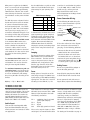
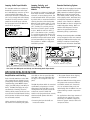
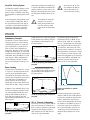
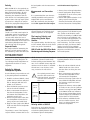
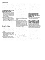
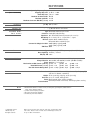
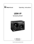
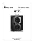
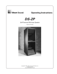
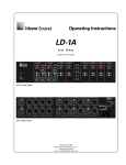
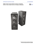
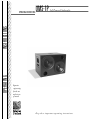
UMS-1P
Self-Powered Subwoofer
OPERATING
INSTRUCTIONS
OPERATING INSTRUCTIONS
Superior
engineering
for the art
and science
of sound.
Keep these important operating instructions.
CONTENTS
Safety Summary
Introduction and Technical Advantages
AC Power
The Modular Rear Panel
Amplification, Limiting, and Cooling System
Applications
Verifying Driver Polarity
Troubleshooting
Specifications
Rear Panel, Input Modules Drawings, and Dimensions
Contact Information
3
4
4
5
6
7
8
9
10
11
12
SYMBOLS USED
THESE
SYMBOLS INDICATE IMPORTANT SAFETY OR OPERATING FEATURES IN THIS BOOKLET AND ON THE CHASSIS.
!
Dangerous voltages:
Important operating
risk of electric shock
instructions
Pour indiquer les risques résultant
Pour indequer important instruc-
de tensions dangereuses
tions
Zu die gefahren von
gefährliche spanning zeigen
Para indicar azares provengo
de peligroso voltajes
Frame or chassis
Protective earth ground
Masse, châssis
Terre de protection
Zu wichtige betriebsanweisung und unterhaltsanweisung zeigen
Rahmen oder chassis
Die schutzerde
Para indicar importante
funcionar y mantenimiento
instrucciones
Armadura o chassis
Tierra proteccionista
DECLARATION OF CONFORMITY ACCORDING TO ISO/IEC GUIDE AND EN 45014
E NVIRONMENTAL S PECIFICATIONS FOR M EYER S OUND E LECTRONICS P RODUCTS :
Operating Temperature 0° to + 45°
Nonoperating Temperature <-40°C or > +75°C
Humidity to 95% at 35°C
Operating Altitude to 4600 m (15,000 ft)
Declares that the product:
Nonoperating Altitude to 6300 m (25,000 ft)
Shock 30g 11 msec half-sine on each
of 6 sides
10Hz to 55Hz (0.010m
Vibration
Conforms to the following Product Specifications
peak-to-peak excursion)
Safety:
EN60065: 1994
1
EMC:
EN55103-1 emmission
EN55103-2 immunity2
The Manufacturer:
MEYER SOUND LABORATORIES, INC.
2832 San Pablo Avenue
Berkeley, California 94702-2204, USA
UMS-1P
This device complies with the requirements of the Low
Voltage Directive 73 / 23 / EEC and the EMC Directive 89 /
336 / EEC.
This device also complies with EN 55103-1 & -2. Operation is
subject to the following two conditions:
(1) this device may not cause harmful interference, and
(2) this device must accept any interference received, including
interference that may cause undesired operation.
2
3K59 COMMERCIAL
AUDIO SYSTEM
Made by Meyer Sound Laboratories
Berkeley, California USA
European Offices:
Meyer Sound Lab. GmbH
Carl Zeiss Strasse 13
56751 Polch, Germany
N757 UMS-1P
Office of Quality Manager
Berkeley, California USA August 31, 2000
!
ENGLISH
• To reduce the risk of electric shock,
disconnect the loudspeaker from the
AC mains before installing audio
cable. Reconnect the power cord only
after making all signal connections.
• Connect the loudspeaker to a twopole, three wire grounding mains
receptacle. The receptacle must be
connected to a fuse or circuit breaker.
Connection to any other type of
receptacle poses a shock hazard and
may violate local electrical codes.
• Do not install the loudspeaker in wet
or humid locations without using
weather protection equipment from
Meyer Sound.
• Do not allow water or any foreign
object to get inside the loudspeaker.
Do not put objects containing liquid
on, or near, the unit.
• To reduce the risk of overheating the
loudspeaker, avoid exposing it to
direct sunlight. Do not install the unit
near heat-emitting appliances, such
as a room heater or stove.
• This loudspeaker contains potentially
hazardous voltages. Do not attempt
to disassemble the unit. The unit
contains no user-serviceable parts.
Repairs should be performed only by
factory-trained service personnel.
FRANÇAIS
• Pour réduire le risque d’électrocution,
débrancher la prise principale de
l’haut-parleur, avant d’installer le
câble d’interface allant à l’audio. Ne
rebrancher le bloc d’alimentation
qu’après avoir effectué toutes les connections.
• Branchez l’haut-parleur dans une prise
de courant à 3 dérivations (deux
pôles et la terre). Cette prise doit être
munie d’une protection adéquate
(fusible ou coupe-circuit). Le
branchement dans tout autre genre de
prise pourrait entraîner un risque
d’électrocution et peut constituer une
infraction à la réglementation locale
concernant les installations électriques.
• Ne pas installer l’haut-parleur dans un
SAFETY SUMMARY
endroit où il y a de l’eau ou une
humidité excessive.
• Ne pas laisser de l’eau ou tout objet
pénétrer dans l’haut-parleur. Ne pas
placer de r´cipients contenant un liquide sur cet appareil, ni à proximité
de celui-ci.
• Pour éviter une surchauffe de l’hautparleur, conserver-la à l’abri du soleil.
Ne pas installer à proximité d’appareils dégageant de la chaleur tels
que radiateurs ou appareils de
chauffage.
• Ce haut-parleur contient des circuits
haute tension présentant un danger.
Ne jamais essayer de le démonter. Il
n’y a aucun composant qui puisse être
réparé par l’utilisateur. Toutes les
réparations doivent être effectuées
par du personnel qualifié et agréé par
le constructeur.
DEUTSCH
• Um die Gefahr eines elektrischen
Schlages auf ein Minimum zu
reduzieren, den Lautsprecher vom
Stromnetz trennen, bevor ggf. ein
Audio-Schnittstellensignalkabel
angeschlossen wird. Das Netzkabel
erst nach Herstellung aller
Signalverbindungen wieder einstecken.
• Der Lautsprecher an eine geerdete
zweipolige Dreiphasen-Netzsteckdose
anschließen. Die Steckdose muß mit
einem geeigneten Abzweigschutz
(Sicherung oder Leistungsschalter)
verbunden sein. Der Anschluß der
unterbrechungsfreien Stromversorgung
an einen anderen Steckdosentyp kann
zu Stromschlägen führen und gegen
die örtlichen Vorschriften verstoßen.
• Der Lautsprecher nicht an einem Ort
aufstellen, an dem sie mit Wasser
oder übermäßig hoher
Luftfeuchtigkeit in Berührung kommen könnte.
• Darauf achten, daß weder Wasser
noch Fremdkörper in das Innere den
Lautsprecher eindringen. Keine
Objekte, die Flüssigkeit enthalten, auf
oder neben die unterbrechungsfreie
Stromversorgung stellen.
3
• Um ein Überhitzen dem Lautsprecher
zu verhindern, das Gerät vor direkter
Sonneneinstrahlung fernhalten und
nicht in der Nähe von wärmeabstrahlenden Haushaltsgeräten (z.B.
Heizgerät oder Herd) aufstellen.
• Im Inneren diesem Lautsprecher herrschen potentiell gefährliche
Spannungen. Nicht versuchen, das
Gerät zu öffnen. Es enthält keine vom
Benutzer reparierbaren Teile.
Reparaturen dürfen nur von ausgebildetem Kundenienstpersonal
durchgeführt werden.
ESPAÑOL
• Para reducir el riesgo de descarga
eléctrica, desconecte de la red el
altoparlante antes de instalar el cable
de señalización de interfaz de la segnale. Vuelva a conectar el conductor
flexible de alimentación solamente
una vez efectuadas todas las interconexiones de señalizatción.
• Conecte el altoparlante a un tomacorriente bipolar y trifilar con neutro de
puesta a tierra. El tomacorriente debe
estar conectado a la protección de
derivación apropiada (ya sea un
fusible o un disyuntor). La conexión a
cualquier otro tipo de tomacorriente
puede constituir peligro de descarga
eléctrica y violar los códigos eléctricos locales.
• No instale el altoparlante en lugares
donde haya agua o humedad excesiva.
• No deje que en el altoparlante entre
agua ni ningún objeto extraño. No
ponga objetos con líquidos encima de
la unidad ni cerca de ella.
• Para reducir el riesgo de sobrecalentamiento, no exponga la unidad a los
rayos directos del sol ni la instale
cerca de artefactos que emiten calor,
como estufas o cocinas.
• Este altoparlante contiene niveles de
voltaje peligrosos en potencia. No
intente desarmar la unidad, pues no
contiene piezas que puedan ser repardas
por el usuario. Las reparaciones deben
efectuarse únicamente por parte del
personal de mantenimiento capacitado
en la fábrica.
UMS-1P: INTRODUCTION AND TECHNICAL ADVANTAGES
Thank you for purchasing the Meyer
Sound UMS-1P: a compact, self-powered
subwoofer system that provides powerful low frequency extension in applications where both audio quality and cabinet size are critical considerations.
Although designed principally as a lowend companion for Meyer Sound's UPM1P reinforcement loudspeaker, the UMS1P is equally adaptable-for use in conjunction with other Meyer Sound loudspeaker models such as HD-1, HM-1/1S,
and UPA-1P/2P.
The UMS-1P's bass reflex cabinet houses
dual MS-410,10-inch cone drivers, active
signal processing (including Meyer
Sound's proprietary phase correction circuits) and a two-channel power amplifier with total maximum burst power of
400W. Performance is exemplary in every
respect, with higher acoustic power out-
put and lower distortion than normally
expected from such a compact cabinet.
The UMS-1P is conservatively rated at a
continuous output of 108dB SPL (127dB
peak) within its operating range of 25200Hz.
As with all Meyer Sound self-powered
loudspeaker systems, the UMS-1P offers
superior performance and improved reliability when compared to conventional
separate speaker and amplifier combinations. Because amplifiers and control
electronics are precisely matched to the
dynamic characteristics of the drivers,
self-powered systems are inherently
capable of producing more power with a
flatter response and significantly lower
distortion. The self-powered concept
also simplifies installation, eliminates
external amplifier racks and drive processing, and avoids the losses intro-
duced by long speaker cable runs or
70/100V distributed schemes.
The UMS-1P's internal amplifier employs
Meyer Sound's complementary output
stage MOSFET design, with separate
amplifier channels dedicated to each
driver. Driver protection limiting and AC
transient suppression on the power supply ensure system reliability, while dual
locking PowerCon connectors facilitate
AC looping. A separate optional module
integrates the UMS-1P into Meyer
Sound's PC-based RMS monitoring and
control network system.
The UMS-1P's durable cabinet is constructed from birch plywood and covered
with a hardened, textured black finish.
A pole-mount (for supporting a UPM-1P
or other Meyer Sound product) is integral to the cabinet.
AC POWER
The UMS-1P uses a PowerCon 3-pole AC
mains system with locking connectors
that prevent inadvertent disconnection.
It also has a looping feature, discussed
below, which allows multiple UMS-1Ps to
be daisy-chained. The blue connector
serves as the power input; the gray connector is used in looping units together.
The unit must, of course, have the correct power plug for the AC power in the
area in which it will be used.
Engagement
Separation
1
2
2
1
3
The power supply suppresses high voltage transients up to several kilovolts
and also filters EMI (radio frequencies
and noise present) on the incoming AC
voltage.
The UMS-1P can withstand continuous
voltages up to 264V and allows any
combination of voltage to GND (i.e.
Neutral-Line-GND, Line-Line-GND).
Continuous voltages higher than 264V
may damage the unit.
Voltage Requirements
Two versions of the UMS-1P are available: a switchable 115/230V and a
non-switch-able 100V-only version.
The 100V version will operate properly
when receiving between 87-113V. On
the switchable version, the voltage
switch must be checked and set at
either 115V or 230V. When set to 115V,
the UMS-1P will operate properly when
the AC remains within the range of 105130V. If set to 230V, the unit operates
safely and without audio discontinuity
within the range of 210-260V. Operating
outside these ranges or with the voltage
switch set improperly could damage the
unit.
After applying AC power, the system is
muted while the circuitry charges up
and stabilizes. After two seconds, the
On/Temp. LED on the user panel illuminates green, the system unmutes and is
ready to pass audio signals. If the
On/Temp. LED does not illuminate or
the system does not respond to audio
input after ten seconds, consult the
Trouble-shooting section.
4
The UMS-1P's power supply uses stored
energy to continue functioning for
about 10 AC cycles if the voltage
decreases below 100V or 200V (a condition known as brownout), depending on
the setting. The precise length of time
the unit functions during brownout
depends on the operating level and how
low the voltage drops. The unit turns off
if the voltage does not increase above
the minimum for 1 to 5 seconds. If the
UMS-1P shuts down due to brownout,
the power supply automatically turns on
if the voltage returns to the normal
operating range. If the UMS-1P does not
turn back on after ten seconds, consult
the Troubleshooting section.
Note: We recommend that the supply be
operated at least a few volts away
from the upper and lower bounds
of the operating range to avoid
possible shutdown.
Current Requirements
Each UMS-1P requires approximately 3A
RMS max @115V for proper operation.
This allows up to five UMS-1Ps to be
powered from one 15A breaker.
When power is applied to the UMS-1P,
there is a current inrush of approximately 12 Apk (at 115V) for approximately
20 milliseconds. Take this into account
when selecting the electrical service and
circuit breakers use dto power the UMS1P.
The UMS-1P presents a dynamic load to
the AC mains which causes the amount
of current to fluctuate between quiet
and loud operating levels. Since different types of cables and circuit breakers
heat up and trip at varying rates, it is
essential to understand the types of current ratings and how they correspond to
circuit breaker and cable specifications.
The maximum continuous RMS current
is the maximum RMS current over a
duration of at least 10 seconds. It is
used to calculate the temperature
increase in cables, which is used to
select cables that conform to electrical
code standards. It is also used to select
the rating for slow-reacting thermal
breakers.
The maximum burst RMS current is the
maximum RMS current over a one second duration. It is used to select the
rating for most magnetic breakers.
The maximum instantaneous peak current during burst is used to select the
rating for fast-reacting magnetic breakers and to calculate the peak voltage
drop in long AC cables according to the
formula
Use the table below as a guide to select
cables and circuit breakers with appropriate ratings for your operating voltage.
UMS-1P Current Ratings
3.15A fuse is used whether the product
is set for 100V, 115V, or 230V. If a fuse
should ever trip, contact your local
Meyer Sound Service Center or the
Service Department at the Meyer Sound
production facility.
115V
230V
100V
Power Connector Wiring
.13A
.065A
.15A
1A
.5A
1.2A
Max. Burst RMS
1.3A
.65A
1.5A
Use the following AC cable wiring diagram to create international or specialpurpose power connectors:
Max Peak During Burst
2.9A
2A
3.3A
Idle RMS
Max. Continuous RMS
To determine the minimum total service
power required by a system comprised
of UMS-1Ps and/or other Meyer Sound
self-powered loudspeaker systems, add
their maximum continuous RMS currents
together. We recommend allowing an
additional 30% above the minimum
amperage to prevent peak voltage drops
at the service entry and nuisance tripping.
Looping
The internal electronics package of the
UMS-1P makes use of an unswitched,
direct connection. The blue connector
serves as the power input; to loop an
additional unit, simply attach a cable
from the grey connector of the first
loudspeaker system to the blue connector of the second, and so on.
brown = hot
blue =
neutral
yellow/green =
earth ground
(chassis)
AC cable color code
If the colors referred to in the diagram
don't correspond to the terminals in
your plug, use the following guidelines:
• Connect the blue wire to the terminal
marked with an N or colored black.
• Connect the brown wire to the terminal marked with an L or colored red.
• Connect the green and yellow wire to
the terminal marked with an E or
or colored green or green and yellow.
Safety Issues
Do not use a ground-lifting adapter or
cut the AC cable ground pin.
Fuses
Always replace a fuse with one of the
same rating and type. The UMS-1P uses
a quick-acting 3.15A, 250V low breaking
capacity fuse. The same fuse is used for
all settings on the UPM-1P, i.e., the
Keep all liquids away from the UMS-1P
to avoid hazards from electrical shock.
The rear panel of the UMS-1P has two
slots for processor modules. The top slot
contains the Audio Input and Control
Module; the bottom slot contains the
optional Remote Monitoring System™
(RMS) Module. A blank plate covers the
bottom slot if RMS is not installed.
Each module uses a three-pin, female
XLR audio input connector with a 10kΩ
balanced input impedance wired with
the following convention:
Audio Input
Pin 2
Pin 3
Case
with XLR connectors for balanced signal
sources. A single audio source can drive
multiple UMS-1Ps with a paralleled
input loop, creating an un buffered
hardwired loop connection, with negligible loss in signal level. For example,
since the input impedance of one UMS1P is 10kΩ, looping 10 UMS-1Ps produces a balanced input impedance of
1kΩ. With a 100Ω audio source, the
500Ω load results in only a .8 dB loss.
Vpkdrop = Ipk x Rtotal cable
Do not operate the unit with worn or
frayed cables; replace them immediately.
THE MODULAR REAR PANEL
There are two interchangeable Audio
Input and Control Modules with optimized connectors and controls for different applications.
Pin 1
-220 kΩ to chassis and earth
ground (ESD clamped)
-Signal
-Signal
-Earth (AC) ground and chassis
Pins 2 and 3 carry the input as a differential signal. Use standard audio cables
5
For drawings of the modules see page 11.
Looping Audio Input Module
This standard module uses a balanced,
female XLR connector for audio input
and a male XLR loop connector to interconnect multiple loudspeakers. The
audio input connector is hardwired with
pin 2 hot to comply with audio industry
standards. The loop connector, wired in
parallel to the audio input, transmits
the input signal even if the UMS-1P is
turned off for any reason.
GND 1
Circuit 2
3
1
2
3
+
-
Looping Audio Input
10k Ω Balanced
220k Ω
Case
Earth /
Chassis
Limit
Input
On / Temp.
Loop
Looping Audio Input Module
Looping, Polarity, and
Attenuating Audio Input
Module
Remote Monitoring System
The UMS-1P can be equipped to operate
with the Remote Monitoring System
(RMS) network and software application.
RMS displays signal and power levels,
driver status, limiter activity, the state
of the polarity switch, attenuator level,
and amplifier temperature for all loudspeakers in the network on a Windowsbased PC. RMS can also be configured to
enable loudspeaker muting. RMS is an
excellent field diagnostic tool that
removes the guesswork from troubleshooting during a performance.
This module has a balanced, female XLR
audio input connector, a male XLR loop
connector, an input polarity switch, and
a level attenuator knob. The input polarity switch offers a convenient method of
reversing the phase of the loudspeaker.
When the input polarity switch is in the
up (+) position, pin 2 is hot relative to
pin 3, resulting in a positive pressure
wave when a positive signal is applied
to pin 2. When the switch is down (-),
pin 3 is hot relative to pin 2, resulting
in a positive pressure wave when a positive signal is applied to pin 3. The level
attenuator knob operates between 0 dB
(no level attenuation) in a fully clockwise position to -18dB in a fully counterclockwise position.
All Meyer Sound loudspeakers with RMS
can be integrated on the same network.
Installing an RMS module requires only
a Phillips screwdriver. Contact Meyer
Sound for more information about RMS.
GND 1
Circuit 2
3
1
2
3
+
-
Looping Polarity & Attn. Audio Input
10k Ω Balanced
220k Ω
- 12
- 15
-9
-6
-3
Case
Polarity
115
23
0
Earth /
Chassis
+
Limit
-18
Input
On / Temp.
Loop
0
Attn dB
~
VOLTAGE BEFORE APPLYING POWER
CAUTIONS: SET
RISK OF FIRE REPLACE WITH F3.15A - 250V FUSE
ATTENTION: UTILISER UN FUSIBLE DE RECHANGE DE MÊME TYPE DE F3.15A - 250V
iv
ct
A
R
es
k
et
ic
e
AC Loop Output 115 / 230V
50-60Hz 15A MAX
Class 1 Wiring
in
F3.15A 250V
W
!
rv
Meyer Sound
Model UPM-1P
Se
~
AC Input 115 / 230V
50-60Hz 3A MAX
ity
Network
Remote
Monitor
System
User Panel with RMS option and Polarity and Attenuaing Audio Input Module
AMPLIFICATION, LIMITING, AND COOLING SYSTEMS
Amplification and Limiting
Each of the MS-410 drivers in the UMS1P is powered by one channel of a proprietary Meyer Sound amplifier utilizing
complementary power MOSFET output
stages (class AB, bridged, 225 Wrms/ch
burst). The UMS-1P employs two separate methods of limiting: Excursion
Limiting which protects the drivers from
over excursion and Sub Channel Limiting
which prevents the drivers from damage
due to thermal overload.
Limiter activity for the Excursion and
Sub channel is indicated by two yellow
Limit LEDs on the rear panel (the EXC.
Limit LED is above the SUB Limit LED).
See page 11 for a diagram of the user
panel.
The UMS-1P performs within its acoustical
specifications and operates at a nomal
temperature if the limit LEDs are on for
no longer than two seconds, and off for
at least one second. If either LED
remains on for longer than three seconds,
that channel will operate with these
characteristics:
• Increasing the input level will not
increase the volume.
6
• The system distorts due to clipping
and nonlinear driver operation.
While the UMS-1P limiters fully protect
the system under overload conditions
and exhibit smooth sonic characteristics; we recommend that you do not
intentionally drive the UMS-1P into continuous limiting to attain compression
effects.
For applications where large amounts of
compression are required, we recommend using an outboard compressor/
limiter for greater control of limit and
compressor effects.
Amplifier Cooling System
The UMS-1P's amplifier employs a natural convection cooling system. Always
allow for proper ventilation when using
the loudspeaker in tightly packed conditions.
If the temperature of the heatsink reaches 85°C (185°F), the On/Temp. LED on
the rear panel turns from green (On) to
red (Temp.) and the limiter threshold is
lowered to a safe level to prevent the
system from overheating. Under high
temperature conditions the output level
is reduced 6 dB. When the heatsink temperature decreases to 75°C (167°F), the
On/Temp. LED changes from red to green
and the limiter threshold returns to normal.
!
You must have 4” of clearance between the UMS-1P
and any wall surfaces for
proper convection cooling.
!
The heatsink can reach temperatures of up to 185°F
(85°C) during normal operation. Use caution to avoid
injury due to the tremendous
heat.
APPLICATIONS
The UMS-1P is used to extend the low
frequency response of a sound system,
complementing systems in a wide variety of applications in sound reinforcement as well as music playback and
monitoring. Though it can be used with
all Meyer Sound products, it is the ideal
compliment to the UPM-1P self-powered
loudspeaker. Using the UMS-1P in a fullrange system is fairly straightforward
but the following concepts are important to consider before installing a system.
Room Loading
The placement of the UMS-1P in a room
or a space is critically important to the
response of the loudspeaker system.
The subwoofer's placement in the room
working with the geometric shape of the
space will affect a loudspeaker's frequency response due to the longer
wavelengths of these lower bands interacting with the walls, ceiling, and floor.
A UMS-1P placed on a floor and against
a wall (quarter-space loading) will gain
approximately 12 dB compared to its
free field response.
12 dB low frequency gain compared to
free field.
A UMS-1P placed on the floor in a corner (one-eighth space loading) will gain
approximately 18 dB compared to its
free field response.
The following graph represents the
approximate change in dB SPL for frequencies under 125Hz of a single UMS1P as it is moved away from a boundary.
Some frequencies will be aided by this
rear reflection, while others will have
opposing phase, resulting in an approximate attenuation. The distance is based
on the distance in meters from the wall
behind the loudspeaker to the acoustical
center of the UMS-1P. All dB SPL measurements are made with the microphone on axis to the loudspeaker.
4
dB SPL relative to free-space response.
Introductory Concepts
2
0
-2
-4
-6
-8
0
0.5
1
1.5
2
2.5
3
3.5
4
4.5
Distance in meters between wall and acoustical center of speaker.
A UMS-1P or any subwoofer hung in the
air with no boundary conditions would
not add any additional SPL from room
loading, while a UMS-1P placed on a
floor (half-space loading) will gain
approximately 6 dB compared to its free
field response.
Distance to Boundary vs. dB SPL
below 125
18 dB low frequency gain compared to
free field.
SPL vs. Distance to Boundary
6 dB low frequency gain compared to
free field.
As we have seen in the previous illustrations, the placement of a UMS-1P on a
floor or against a boundary significantly
changes the low frequency response
when compared to free field measurement of the same loudspeaker.
7
To better understand the graph above,
imagine a UMS-1P with a wall behind it.
As you move the UMS-1P away from the
wall the graph above shows how the
response of the loudspeaker will change.
For example, if the UMS-1P is placed 1
meter from a wall and is measured on
axis to the loudspeaker, you will see a
-5 dB change in the low frequency as
illustrated by the dotted lines on the
graph.
Polarity
With the UMS-1P in close-proximity to,
and coplanar with, the UPM-1P or other
Meyer Sound loudspeakers, all units
should be set to the same polarity.
Separating the subwoofers from the
main cabinets in a loudspeaker system
by more than 5 feet may require polarity reversal or a delay line to compensate for the propagation delay between
the loudspeakers and the measurement
position.
and CP-10 Parametric Equalizer to:
Measurement and Correction
Tools
• choose, place, and array loudspeakers;
• measure propagation delays between
loudspeakers to set the correct polarity and delay times;
• measure and equalize variations in frequency response caused by the
acoustical environment and the placement and interaction of loudspeakers.
It is recommended that even the most
carefully assembled sound systems be
analyzed with precise measurement
tools. We recommend using the Meyer
Sound SIM® System II Sound Analyzer
SUBWOOFER LEVEL CONTROL
The VX-1:
The VX-1 is an ideal control option for
loudspeaker systems incorporating the
UMS-1P. The VX-1 is a stereo virtual
crossover which allows the user to
adjust the gain, switch between stereo
and mono distribution of two inputs and
make shelving EQ adjustments to the
left and right sides of the system.
speaker(s). With independent control of
the main outputs and sub levels, their
relative proportions can be adjusted.
The Looping, Polarity, and
Attenuating Audio Input
Module:
Separate Feeds:
This optional module, described on page
6 of this manual, allows for level control
on the user panel of the UMS-1P.
One simple method of attenuating the
UMS-1P is to feed separate signals to
the subwoofer(s) and to the main loud-
UMS-1P with the UPM-1P for Music
Monitoring and Listening Purposes
Because of the flatter phase and frequency response of our UltraSeries products, (similar to the HD Series studio
monitors) the teaming of a UMS-1P with
two (in stereo) or more UPM-1Ps (such
as 5.1 surround sound applications) can
be a great choice for high definition
music monitoring. The wider coverage
pattern also helps give listeners better
imaging in stereo and 5.1 playback
without the over-localization which can
plague the near field with a narrower
horn loaded product.
VERIFYING DRIVER POLARITY
Use the following test procedure to verify the polarity between two UMS-1Ps.
1. Establish a reference UMS-1P, a loudspeaker that has not been tampered
with or damaged. Mark this loudspeaker as the reference.
2. Place the UMS-1P you want to test
next to the reference UMS-1P.
3. Place a measurement microphone 3
feet from the loudspeakers on the
axis between the loudspeakers. See
thedrawing on this page.
4. Connect a signal source to the reference loudspeaker and note the frequency response and overall level.
5. Apply the same signal to the UMS-1P
under test with the first loudspeaker
still connected.
The polarity is correct if the frequency
response remains constant with a 5 to 6
!
Reference
UMS-1P
Since polarity reversal causes
excessive driver excursion at
high source levels, use moderate levels when conducting
these tests.
Front of speaker
Polarity In Adjacent
Loudspeaker Systems
dB SPL increase in amplitude. Broadband
cancellation (decreased overall level)
indicates polarity reversal between cabinets. A 2 to 3 dB SPL increase may indicate that one of the drivers in the UMS1P under test is out of phase, in this
case, proceed to the next section.
3 Feet
UMS-1P
Under Test
Front of speaker
Incorrect driver polarity impairs system
performance and may damage the drivers. All Meyer Sound loudspeakers are
shipped with the drivers in correct
alignment.
Polarity within a UMS-1P
If the driver or circuit wiring has been
removed or disassembled it is essential
to check the polarity between drivers
and between adjacent loudspeakers.
8
Use the following test procedure to verify polarity between drivers in the same
loudspeaker:
1. Place the reference UMS-1P and the
UMS-1P under test side to side so
that the drivers are facing the same
direction.
2. Place a measurement microphone 3
feet from the loudspeakers on the
axis between the loudspeakers.
3. Connect a full range signal to the reference UMS-1P loudspeaker and note
the frequency response and sound
pressure level.
4. Compare the reference and test UMS1P results one at a time. A significant
decrease in energy from 40 to 100Hz
in the UMS-1P under test indicates a
driver reversal. Contact Meyer Sound
Technical Support for information on
Service Center or field correction.
5. If the reference and UMS-1P under
test have similar responses, then
there is no internal polarity error
within the loudspeaker.
TROUBLESHOOTING
This section suggests several possible
solutions to problems encountered by
UMS-1P users, and is not intended to be
a comprehensive troubleshooting guide.
Please contact Meyer Sound for additional information and documentation.
THE ON/TEMP. LED
DOES NOT ILLUMINATE AND THERE IS NO AUDIO.
1. Make sure the AC power cable is the
correct type for the regional voltage
and that it is securely connected to
the AC inlet, then unplug and reconnect the AC cable.
2. Check that the voltage selector
switch is set properly. If you need to
operate in the 100V range, be sure
you are using the 100V version of the
UMS-1P.
3. Use an AC voltmeter to verify that
the AC voltage is within the ranges
95-105V, 110-130V, or 220-240V.
THE ON/TEMP. LED IS ILLUMINATED
BUT THERE IS NO SOUND.
1. Verify that the audio source (mixer,
EQ, delay) is sending a valid signal.
2. Make sure the XLR cable is securely
fastened to the XLR audio input connector.
3. Verify that the XLR cable is functioning by substituting another cable or
by using the cable in question in a
working system.
4. Send the audio signal to another
loudspeaker to insure signal presence
and that the level is within the proper range. Turn the source level down
before reconnecting the audio input
and increase the level slowly to avoid
a sudden blast of sound.
5. If possible, monitor the audio source
with headphones.
Hum or noise is produced by
the loudspeaker.
1. Disconnect the audio input. If the
noise persists, the problem is within
the UMS-1P. In this case return the
unit to the factory or nearest authorized service center. If the hum ceases, the noise originates somewhere
earlier in the signal path.
2. Make sure the XLR cable is securely
fastened to the XLR audio input connector.
3. Send the audio signal to another
loudspeaker to insure signal presence
and that the level is within the proper range. Turn the source level down
before reconnecting the audio input
and increase the level slowly to avoid
a sudden blast of sound.
4. Hum or noise can be produced by a
ground loop. Since the UMS-1P is
effectively ground-lifted, the loop
must be broken elsewhere in the system.
5. If possible, monitor the audio source
with headphones.
The audio produced by the
loudspeaker is distorted or
compressed but the limit light
is not illuminated.
1. Make sure the XLR cable is securely fastened to the XLR audio input connector.
9
2. Send the audio signal to another
loudspeaker to insure that the level is
within the proper range. Turn the
source level down before reconnecting the audio input and increase the
level slowly to avoid a sudden blast
of sound.
3. Monitor the audio source with headphones.
The audio produced by the
loudspeaker is highly compressed and the limit light is
constantly red.
1. Turn down the level of the input signal to the loudspeaker system.
There is sound but it is does
not seem to be at full power
and the On/Temp. LED is red.
This occurs in conditions where the
heatsink temperature reaches 85°C
(185°F), indicating that the amplifier is
thermally overloaded. The limiter threshold has dropped to a safe level, so the
audio level is reduced.
1. Make sure there is enough clearance
above, below, and behind the unit.
2. Make sure there is sufficient air flow
around the unit.
3. Avoid exposing the heatsink to direct
sunlight if the ambient temperature
is high.
See the Amplification, Limiting, and
Cooling System section on page 6 and 7
for a complete discussion of the cooling
system.
UMS-1P SPECIFICATIONS
ACOUSTICAL1
( EACH LOUDSPEAKER )
Operating Frequency Range
Frequency Response2
Phase Response2
Maximum Continuous SPL4
Maximum peak SPL3
Maximum short term RMS SPL (<3 sec)
(-6 dB) 360o H; 180ο V
COVERAGE1
TRANSDUCERS
S TA N DA R D AU D I O
INPUT MODULE
AMPLIFIERS
AC POWER
PHYSICAL
NOTES
© 2000 Meyer Sound
Laboratories, Inc.
All rights reserved
25 - 200Hz
±3 dB 29 - 110Hz
± 60o 32 - 110Hz
108 dB
127 dB
116 dB
Sub Frequency (2) MS-410 10-inch cone drivers
Type
Connector
Impedance
XLR Wiring
RF Filter
Differential balanced input circuit
Female XLR; male XLR loop
10 k differential blaanced (between pins 2 and 3)
Pin 1: chassis; Pin 2: + signal; Pin 3: - signal
Common Mode: 425kHz low-pass;
Differential Mode: 142kHz low-pass
Common Mode Rejection Ratio >50dB (50Hz); typically 60dB
>65db (1kHz); typically 75dB
TIM FIlter 80kHz
Type Complementary MOSFET output stages (class AB/bridged)
Burst Capability 225 Wrms / channel
THD, IM, TIM <.02%
Connector
Voltage Selection
Power
Max Continuous RMS Current (>10 sec)
Burst RMS Current (<1 sec)
Max Peak Current During Burst
PowerCon locking AC connector with looping output
105-130 VAC; 208-260 VAC; 47-63Hz (90-105V available)
400 Watts, 1 second burst
@115V: 1A
@230V: .5A
@100V: 1.2A
@115V: 1.3A
@230V: .65A
@100V: 1.5A
@115V: 2.9Apk @230V: 2Apk @100V: 3.3Apk
Dimensions Height: 16.35”; Width: 22.75”; Depth: 17.50” (16” w/out grill)
(415 mm H x 578mm x 445mm D)
Weight 83 lbs (37.65 kg); shipping: 94 lbs (42.72 kg)
Enclosure 0.2 cu. ft. vented, multi-ply birch
Finish Black textured (other options available)
Protective Grill Hex-stamped metal screen frame, charcoal-grey foam covering
1. Measurements taken at 1 meter on-axis, in half space (ground plane) loaded environment, unless otherwise stated.
2. 1/24th octave frequency resolution
3. Pink noise burst signal exitation.
4. Continuous pink noise exitation.
Meyer Sound reserves the right to alter any specification without notice. Please visit our web site at www.meyersound.com
for up-to-date information.
10
REAR PANEL AND OPTIONAL MODULES
Rear panel and optional modules are descrbed on page 5 and 6 of this document
GND 1
Circuit 2
3
1
2
3
+
-
Looping Polarity & Attn. Audio Input
10k Ω Balanced
220k Ω
- 12
- 15
-9
-6
-3
Case
Polarity
115
23
0
Earth /
Chassis
Limit
+
-18
Input
On / Temp.
Loop
0
Attn dB
~
VOLTAGE BEFORE APPLYING POWER
CAUTIONS: SET
RISK OF FIRE REPLACE WITH F3.15A - 250V FUSE
ATTENTION: UTILISER UN FUSIBLE DE RECHANGE DE MÊME TYPE DE F3.15A - 250V
iv
ct
A
R
es
k
et
ic
e
AC Loop Output 115 / 230V
50-60Hz 15A MAX
Class 1 Wiring
in
F3.15A 250V
W
!
rv
Meyer Sound
Model UPM-1P
Se
~
AC Input 115 / 230V
50-60Hz 3A MAX
ity
Network
Remote
Monitor
System
User Panel with RMS option and Polarity and Attenuaing Audio Input Module
GND 1
Circuit 2
3
1
2
3
+
-
Looping Audio Input
10k Ω Balanced
220k Ω
Case
Earth /
Chassis
Limit
Input
On / Temp.
Loop
Looping Audio Input Module
PHYSICAL DIMENSIONS
All units in inches
17.5
Front
(Without Grille Frame)
Top
UL and CSA compliance is
pending. Call Meyer Sound
for current status.
11
Side
CONTACT INFORMATION
Meyer Sound Laboratories, Inc.
2832 San Pablo Avenue
Berkeley, CA 94702
tel: 510.486.1166
fax: 510.486.8356
e-mail: [email protected]
http: www.meyersound.com
05.86.002.01 Rev A
12