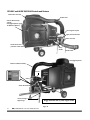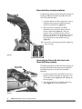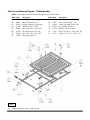
1
DR® COMMERCIAL LEAF & LAWN VACUUM
SAFETY & OPERATING INSTRUCTIONS
Models:
-
Briggs & Stratton 9.0 TQ Intek Engine
Subaru Robin 9HP (13.74 TQ) Engine
Briggs & Stratton 9.0 TQ Intek Engine
READ AND UNDERSTAND THIS MANUAL AND ALL INSTRUCTIONS
BEFORE OPERATING THIS VACUUM.
Congratulations on your purchase of a new DR LEAF and LAWN VACUUM!
We have done our utmost to ensure that your DR LEAF and LAWN VACUUM will be one of the most troublefree and satisfying pieces of equipment you have ever owned. Please let us know of any questions or
problems you may have. We want to answer or correct them as quickly as possible. When you do call, please
have your order number, or serial number handy. For technical assistance, please call Toll-Free 1-800-DROWNER (376-9637) and one of our Technical Support Representatives will be happy to help you. We also
hope to hear from you on how much you like your new helper.
In addition, please tell your friends about your new DR LEAF and LAWN VACUUM! Having DR Owners
spread the word about our products and our way of doing business is the best advertising we can have, and
the best way to help us provide even better service in the years to come.
Thanks once again!
for all of us at
Country Home Products, Inc.
SALES MANAGER
COPYRIGHT
©2007 Country Home Products, Inc. All rights reserved.
DR® Power Equipment
A division of Country Home Products®
127 Meigs Road
Vergennes, VT 05491
Toll-Free phone: 1-800-DR-OWNER (376-9637)
Fax: 1-802-877-1213
Web site: www.dr-owner.com
ii
DR® COMMERCIAL LEAF and LAWN VACUUM
Table of Contents
CHAPTER 1............................................................................................................................. 1
INTRODUCING THE DR LEAF and LAWN VACUUM................................................... 1
Conventions used in this manual ................................................................................... 1
CHAPTER 2............................................................................................................................. 2
GENERAL SAFETY RULES............................................................................................... 2
Labels ............................................................................................................................... 2
Protecting Yourself and Those Around You ................................................................... 4
Operating the Vacuum Safely.......................................................................................... 4
Slope Operation............................................................................................................... 6
Safety for Children ........................................................................................................... 6
Safety with Gasoline-Powered Machines........................................................................ 7
A Note to All Users .......................................................................................................... 8
Additional Information and Potential Changes.............................................................. 8
CHAPTER 3............................................................................................................................. 9
SETTING UP YOUR DR LEAF AND LAWN VACUUM ................................................... 9
DR LEAF and LAWN VACUUM Controls and Features ............................................... 10
Unpacking and Assembling the Machine..................................................................... 11
Attaching Hardware Description................................................................................... 12
Opening the Shipping Container, Installing the Wheels and Caster Wheel Jack*
(Subaru model*)............................................................................................................ 13
Tire Pressure Check ....................................................................................................... 15
Tilt Bed Installation........................................................................................................ 15
Collector Box Installation .............................................................................................. 16
Blower Exit Elbow Assembly Installation ...................................................................... 18
Connecting the Collector Box Inlet Hose to the Blower Exit Elbow Assembly............ 18
Adjusting the Hitch Assembly....................................................................................... 19
Hitch Plate Kit Installation (Optional) .......................................................................... 19
Connecting the DR LEAF and LAWN VACUUM to your Lawn Tractor........................ 20
Lawn Deck Adapter Installation .................................................................................... 21
Connecting the Blower Inlet Vacuum Hose to the Hose Adapter ............................... 23
Connecting the Battery Wire (Electric-Starting Models Only) ..................................... 25
Adding the Engine Oil and Gasoline............................................................................. 26
CHAPTER 4........................................................................................................................... 27
OPERATING YOUR DR LEAF AND LAWN VACUUM ................................................. 27
Before Starting the Engine............................................................................................. 27
Starting and Stopping.................................................................................................... 27
Operating Safety ............................................................................................................ 28
Towing the DR LEAF and LAWN VACUUM.................................................................. 29
Towing Safety................................................................................................................. 29
Slopes and Uneven Terrain ........................................................................................... 30
Operating the Chipper................................................................................................... 31
Use as a Trailer .............................................................................................................. 33
Dumping ........................................................................................................................ 34
LEAF and LAWN VACUUM Tips ................................................................................... 35
CHAPTER 5........................................................................................................................... 36
MAINTAINING THE DR LEAF AND LAWN VACUUM................................................ 36
Regular Maintenance Checklist..................................................................................... 36
Lubrication ..................................................................................................................... 37
Removing and Replacing the Engine Oil ...................................................................... 38
CALL TOLL-FREE 1-800-DR-OWNER
iii
Battery Care (For Electric-Starting Models Only) ......................................................... 39
Charging the Battery ...................................................................................................... 39
Removing and Replacing the Blower Hoses................................................................. 40
Removing and Replacing the Blower Exit Elbow .......................................................... 42
Removing and Replacing the Chipper Blade ................................................................ 43
Removing and Adjusting the Drive Belt (Subaru Engine model) ................................ 44
Removing the Blower/Chipper Engine Unit ................................................................. 45
Disposing of the Battery Responsibly (Electric-Start Models)..................................... 46
Recycling a Used Battery ............................................................................................... 46
End of Season and Storage ........................................................................................... 47
CHAPTER 6........................................................................................................................... 48
TROUBLESHOOTING................................................................................................... 48
Troubleshooting Table................................................................................................... 48
CHAPTER 7........................................................................................................................... 52
PARTS LISTS, SCHEMATIC DIAGRAMS AND WARRANTY........................................ 52
Parts List - Trailer Assembly.......................................................................................... 52
Schematic Diagram - Trailer Assembly......................................................................... 53
Parts List - Blower/Chipper Assembly, B&S Engine..................................................... 54
Schematic Diagram - Blower/Chipper Assembly, B&S Engine.................................... 55
Parts List - Blower/Chipper Assembly, Subaru Engine ................................................ 56
Schematic Diagram - Blower/Chipper Assembly, Subaru Engine ............................... 57
Parts List - Centrifugal Separator, Hose and Blower Exit Elbow Assembly ................. 58
Schematic Diagram - Centrifugal Separator, Hose and Blower Exit Elbow Assembly 59
Parts List and Schematic Diagram - Tilt Bed Assembly ............................................... 60
Parts List and Schematic Diagram - Side Panel Assembly .......................................... 61
Parts List and Schematic Diagram - Rear Panel Assembly .......................................... 62
Parts List and Schematic Diagram - Front Box Cover Assembly ................................. 63
Electrical Schematic....................................................................................................... 64
Warranty......................................................................................................................... 67
iv
DR® COMMERCIAL LEAF and LAWN VACUUM
CHAPTER 1
INTRODUCING THE DR LEAF and LAWN VACUUM
This manual will help you set up and safely operate your new DR COMMERCIAL LEAF and LAWN
VACUUM. Careful adherence to the safety and operating instructions in this manual will ensure many years
of productive use.
Please let us know of any questions you may have. We want to answer them as quickly as possible. When
you do call, please have your order number, or serial number handy. For technical assistance, please call
Toll-Free 1-800-DR-OWNER (376-9637) and one of our Technical Support Representatives will be happy to
help you.
Conventions used in this manual
THIS INDICATES A HAZARDOUS SITUATION, WHICH, IF NOT AVOIDED, COULD RESULT IN DEATH OR
SERIOUS INJURY.
THIS INDICATES A HAZARDOUS SITUATION, WHICH, IF NOT AVOIDED, COULD RESULT IN MINOR OR
MODERATE INJURY.
THIS INFORMATION IS IMPORTANT IN THE PROPER USE OF YOUR MACHINE. FAILURE TO FOLLOW THIS
INSTRUCTION COULD RESULT IN DAMAGE TO YOUR MACHINE OR PROPERTY.
Tip: This is a helpful hint to guide you in getting the most out of your DR LEAF and LAWN VACUUM.
Tools Needed: This indicates you will need a special tool to perform a maintenance function on your
Vacuum.
NOTE: This information may be helpful to you.
If you are ever unsure about an action you are about to take, don’t do it, contact Country Home Products’
Toll-Free support at 1-800-DR-OWNER (376-9637) for help or information.
CALL TOLL-FREE 1-800-DR-OWNER
1
CHAPTER 2
GENERAL SAFETY RULES
READ THIS SAFETY AND OPERATING MANUAL BEFORE YOU USE THE DR LEAF AND LAWN VACUUM.
BECOME FAMILIAR WITH THE SERVICE RECOMMENDATIONS TO ENSURE THE BEST PERFORMANCE
FROM YOUR VACUUM.
Labels
Your DR LEAF and LAWN VACUUM carries prominent labels as reminders for its proper and safe use.
Shown below are copies of all the labels that appear on the equipment. Take a moment to study them and
make a note of their location on your DR LEAF and LAWN VACUUM as you assemble and before you operate
the machine. Replace damaged or missing safety and information labels immediately.
Read the instruction
manual thoroughly before
using this machine.
NEVER insert metal, glass, or
objects other than wood into
the Chipper Hopper. Be
careful when vacuuming to
avoid these materials.
Use approved eye protection
when operating this machine.
Rotating Blades: Keep hands
out of the Chipper and Blower
Inlets as well as the Lawn Deck
when the engines are running.
NEVER operate across lopes, ALWAYS up and down (Max. slope 15º).
SLOW DOWN in rough terrain and on slopes. NEVER operate within
8ft. of a drop-off or bank. #225481
2
Do not allow people or
pets near the machine
when it is operating.
DR® COMMERCIAL LEAF and LAWN VACUUM
On Electric-Start Briggs &
Stratton Engine models, shut off
the Engine by moving the
Throttle to the STOP position;
the Key is for starting ONLY.
#193231
Make sure you add oil before starting the
engine; the unit shipped without oil. Fill
the oil reservoir slowly to make sure you
do not overfill it. #12781
This label reminds you about the importance
of reading and understanding the Safety &
Operating Instructions Manual and of paying
attention to the safety warnings. #188361A
Always raise the three (3) Support Legs on
the Briggs & Stratton Engine model before
towing the DR LEAF and LAWN VACUUM.
#18885
Do not touch and keep combustible
substances away from the engine when it
is hot. #18887
This label is on Robin Engine model
and reminds you to ALWAYS keep clear
of the Drive Belt and to stop the Engine
before servicing. #233711
Never detach a vacuum hose, remove a
cover, or guard while the engine is running.
Unplug the spark plug wire first. #18886
CALL TOLL-FREE 1-800-DR-OWNER
3
Protecting Yourself and Those Around You
THIS IS A HIGH-POWERED MACHINE, WITH MOVING PARTS OPERATING WITH HIGH ENERGY AT HIGH
SPEEDS. YOU MUST USE PROPER CLOTHING AND SAFETY GEAR WHEN OPERATING THIS MACHINE TO
PREVENT OR MINIMIZE THE RISK OF SEVERE INJURY. THIS MACHINE CAN CUT, AND SEVER PARTS OF
YOUR BODY IF THEY BECOME IN CONTACT WITH THE MOVING CHIPPER BLADES. ALWAYS TAKE THE
FOLLOWING PRECAUTIONS WHEN OPERATING THIS MACHINE:
• ALWAYS WEAR PROTECTIVE GOGGLES OR SAFETY GLASSES WITH SIDE SHIELDS WHILE OPERATING
EITHER YOUR TRACTOR LAWN DECK, VACUUM SYSTEM, CHIPPER OR PERFORMING AN ADJUSTMENT
ON YOUR DR LEAF AND LAWN VACUUM TO PROTECT YOUR EYES FROM POSSIBLE FOREIGN
OBJECTS THROWN FROM THE MACHINE.
• WEAR SHOES WITH NON-SLIP TREADS WHEN USING YOUR DR LEAF AND LAWN VACUUM. IF YOU
HAVE SAFETY SHOES, WE RECOMMEND WEARING THEM. DO NOT USE THE MACHINE WHILE
BAREFOOT OR WEARING OPEN SANDALS.
• AVOID WEARING LOOSE CLOTHING OR JEWELRY, WHICH CAN CATCH ON THE MACHINE’S MOVING
PARTS.
• WE RECOMMEND WEARING GLOVES WHILE USING YOUR DR LEAF AND LAWN VACUUM. BE SURE
YOUR GLOVES FIT PROPERLY AND DO NOT HAVE LOOSE CUFFS OR DRAWSTRINGS.
Operating the Vacuum Safely
THIS IS A HIGH-POWERED MACHINE, WITH MOVING PARTS OPERATING WITH HIGH ENERGY AT HIGH
SPEEDS. YOU MUST OPERATE THE MACHINE SAFELY. UNSAFE OPERATION CAN CREATE A NUMBER OF
HAZARDS FOR YOU, AS WELL AS ANYONE ELSE IN THE NEARBY AREA. ALWAYS TAKE THE FOLLOWING
PRECAUTIONS WHEN USING THIS MACHINE:
• NEVER ALLOW PEOPLE WHO ARE UNFAMILIAR WITH THESE INSTRUCTIONS TO USE THE DR LEAF
AND LAWN VACUUM.
• TO BE SAFE, DO NOT OPERATE THE MACHINE NEAR SMALL CHILDREN OR PETS, AND NEVER ALLOW
CHILDREN TO OPERATE THE VACUUM. STOP THE VACUUM ENGINE AND TRACTOR ENGINE WHEN
ANOTHER PERSON OR PET APPROACHES.
• NEVER ALLOW PEOPLE OR PETS TO RIDE IN THE COLLECTOR BOX OR ON THE TRAILER.
• NEVER START THE BLOWER/CHIPPER ENGINE UNLESS IT IS BOLTED FIRMLY TO THE ENGINE
MOUNTING PLATE AND THE MOUNTING PLATE IS ATTACHED FIRMLY TO THE TRAILER CHASSIS
USING THE FOUR (4) RETAINING KNOBS. SEE FIGURE 52 ON PAGE 45.
• CHECK BEHIND YOUR DR LEAF AND LAWN VACUUM BEFORE BACKING UP. YOU CANNOT SEE
DIRECTLY BEHIND THE COLLECTOR BOX.
• NEVER ATTEMPT TO DUMP A LOAD WHILE THE LAWN TRACTOR ENGINE OR THE DR LEAF AND
LAWN VACUUM ENGINE IS RUNNING.
• DO NOT OPERATE IN SANDY AREAS WHERE YOU WILL VACUUM LARGE QUANTITIES OF SAND.
SAND WILL ERODE THE VACUUM HOUSING. CHECK FOR PIN HOLES AFTER EACH USE AND REPLACE
THE HOUSING WHEN PIN HOLES DEVELOP.
4
DR® COMMERCIAL LEAF and LAWN VACUUM
•
DO NOT ATTEMPT TO OPEN THE COLLECTOR BOX WHEN YOUR DR LEAF AND LAWN VACUUM
ENGINE OR YOUR LAWN DECK ENGINE IS OPERATING. DEBRIS MAY EXIT AT HIGH VELOCITY OUT
OF THE SMALL OPENINGS CREATED IN THE SEAMS OF THE COLLECTOR BOX AS YOU UNLATCH THE
COLLECTOR BOX PANELS.
•
NEVER OPERATE THE MACHINE ON SLOPES GREATER THAN 15°.
•
WHEN USING THE DR LEAF AND LAWN VACUUM AS A TRAILER, BE SURE TO SECURE THE LOAD.
•
NEVER TOW THE DR LEAF AND LAWN VACUUM FASTER THAN 8 MPH.
•
KEEP YOUR HANDS OUT OF THE CHIPPER HOPPER AND VACUUM INLETS WHILE THE LAWN
TRACTOR AND THE DR LEAF AND LAWN VACUUM ENGINES ARE RUNNING. IF IT BECOMES
NECESSARY TO PUSH MATERIAL INTO THE HOPPER, USE A SMALL DIAMETER STICK.
•
ALWAYS SHUT OFF THE LAWN TRACTOR ENGINE AND THE DR LEAF AND LAWN VACUUM ENGINE,
AND DISCONNECT THE SPARK PLUG WIRE BEFORE ATTEMPTING TO CLEAR ANY OBSTRUCTIONS IN
THE HOSES OR CHIPPER HOPPER.
•
THE EXHAUST AREA ON THE ENGINE BECOMES VERY HOT WITH USE. ALLOW THE ENGINE TO
COOL BEFORE DOING MAINTENANCE OR MAKING ADJUSTMENTS.
•
KEEP YOUR HANDS AND COMBUSTIBLE SUBSTANCES AWAY FROM THE ENGINE WHEN IT IS HOT
AND CLEAN THE ENGINE AREA AFTER EACH USE.
•
USE THE DR LEAF AND LAWN VACUUM ONLY IN DAYLIGHT.
•
ALWAYS FEED THE CHIPPER FROM THE CHIPPING ZONE (FIGURE 28 ON PAGE 28). NEVER STRADDLE
OR REACH OVER THE ENGINE AREA AT ANY TIME.
•
USE ONLY YOUR HANDS TO OPERATE THE DR LEAF AND LAWN VACUUM ENGINE CONTROLS.
ALWAYS DISMOUNT YOUR LAWN TRACTOR WHEN STARTING AND STOPPING THE DR LEAF AND
LAWN VACUUM ENGINE TO PREVENT CONTACT WITH THE HOT MUFFLER.
•
DO NOT, UNDER ANY CONDITIONS, REMOVE, BEND, CUT, FIT, WELD, OR OTHERWISE ALTER
STANDARD PARTS ON THE DR LEAF AND LAWN VACUUM. MODIFICATIONS TO YOUR MACHINE
COULD CAUSE PERSONAL INJURIES AND WILL VOID YOUR WARRANTY.
•
DO NOT ALTER OR TAMPER WITH SAFETY DEVICES OR SHIELDS. MAKE SURE THEY ARE IN PROPER
POSITION.
•
WHILE USING THE DR LEAF AND LAWN VACUUM, DO NOT HURRY OR TAKE THINGS FOR GRANTED.
•
NEVER LEAVE THE DR LEAF AND LAWN VACUUM UNATTENDED WITH ITS MOTOR RUNNING.
•
DO NOT OPERATE THE MACHINE WHEN UNDER THE INFLUENCE OF ALCOHOL, DRUGS, OR
MEDICATION.
CALL TOLL-FREE 1-800-DR-OWNER
5
Slope Operation
SLOPES ARE A MAJOR FACTOR RELATED TO TIP OVER ACCIDENTS, WHICH CAN RESULT IN SEVERE
INJURY. ALL SLOPES REQUIRE CAUTION. IF YOU FEEL UNEASY ON A SLOPE, DO NOT VACUUM IT.
ALWAYS TAKE THE FOLLOWING PRECAUTIONS WHEN USING THIS MACHINE ON SLOPES:
ALWAYS:
•
VACUUM UP AND DOWN THE FACE OF SLOPES, NEVER ACROSS. EXERCISE EXTREME CAUTION
WHEN CHANGING DIRECTION ON SLOPES.
•
•
REMOVE OBJECTS SUCH AS STONES, GLASS AND METAL OBJECTS SUCH AS CANS.
WATCH OUT FOR HOLES, RUTS, OR BUMPS. TALL GRASS CAN HIDE OBSTACLES.
NEVERS:
•
NEVER VACUUM NEAR DROP-OFFS, DITCHES, OR EMBANKMENTS. YOUR TRACTOR AND THE
VACUUM MAY TIP OVER.
•
•
NEVER VACUUM ON SLOPES GREATER THAN 15 DEGREES OR ANY EXCESSIVELY STEEP SLOPES.
NEVER VACUUM ON WET SLOPES. REDUCED TRACTION COULD RESULT IN SLIPPING AND A
POSSIBLE ROLL OVER.
Safety for Children
TRAGIC ACCIDENTS CAN OCCUR IF THE OPERATOR IS NOT ALERT TO THE PRESENCE OF CHILDREN.
CHILDREN ARE OFTEN ATTRACTED TO THE TRACTOR AND THE VACUUMING/CHIPPING ACTIVITY.
NEVER ASSUME THAT CHILDREN WILL REMAIN WHERE YOU LAST SAW THEM.
• KEEP CHILDREN OUT OF THE WORK AREA AND UNDER THE WATCHFUL CARE OF A RESPONSIBLE
ADULT.
•
BE ALERT AND ALWAYS TURN OFF THE LAWN TRACTOR ENGINE AND THE DR LEAF AND LAWN
VACUUM ENGINE IF CHILDREN ENTER THE WORK AREA.
•
BEFORE AND WHILE MOVING BACKWARDS, LOOK BEHIND, AND DOWN FOR SMALL CHILDREN.
YOU CANNOT SEE DIRECTLY BEHIND THE COLLECTOR BOX.
•
•
NEVER ALLOW CHILDREN TO OPERATE THE TRACTOR OR VACUUM.
•
USE EXTRA CARE WHEN APPROACHING BLIND CORNERS, SHRUBS, TREES, OR OTHER OBJECTS THAT
MAY OBSCURE YOUR VISION.
6
NEVER ALLOW CHILDREN TO PLAY IN THE COLLECTOR BOX. IF THEY BECOME TRAPPED IN THE
ENCLOSURE THEY MAY BE EXPOSED TO TEMPERATURES SIMILAR TO LEAVING A CHILD IN A CAR
WITH THE WINDOWS CLOSED ON A SUNNY DAY.
DR® COMMERCIAL LEAF and LAWN VACUUM
Safety with Gasoline-Powered Machines
GASOLINE IS A HIGHLY FLAMMABLE LIQUID. GASOLINE ALSO GIVES OFF FLAMMABLE VAPOR THAT
CAN BE EASILY IGNITED AND CAUSE A FIRE OR EXPLOSION. NEVER OVERLOOK THE HAZARDS OF
GASOLINE. ALWAYS FOLLOW THESE PRECAUTIONS:
•
NEVER RUN THE ENGINE IN AN ENCLOSED AREA OR WITHOUT PROPER VENTILATION AS THE
EXHAUST FROM THE ENGINE CONTAINS CARBON MONOXIDE, WHICH IS AN ODORLESS,
TASTELESS, AND DEADLY POISONOUS GAS.
•
STORE ALL FUEL AND OIL IN CONTAINERS SPECIFICALLY DESIGNED AND APPROVED FOR THIS
PURPOSE AND KEEP AWAY FROM HEAT AND OPEN FLAME, AND OUT OF THE REACH OF CHILDREN.
•
FILL THE GASOLINE TANK OUTDOORS WITH THE ENGINE OFF AND ALLOW THE ENGINE TO COOL
COMPLETELY. DO NOT HANDLE GASOLINE IF YOU OR ANYONE NEARBY IS SMOKING, OR IF YOU'RE
NEAR ANYTHING THAT COULD CAUSE IT TO IGNITE OR EXPLODE. REPLACE THE FUEL TANK AND
FUEL CONTAINER CAPS SECURELY.
•
IF YOU SPILL GASOLINE, DO NOT ATTEMPT TO START THE ENGINE. MOVE THE MACHINE AWAY
FROM THE AREA OF THE SPILL AND AVOID CREATING ANY SOURCE OF IGNITION UNTIL THE GAS
VAPORS HAVE DISSIPATED. WIPE UP ANY SPILLED FUEL TO PREVENT A FIRE HAZARD AND PROPERLY
DISPOSE OF THE WASTE.
•
ALLOW THE ENGINE TO COOL COMPLETELY AND EMPTY THE COLLECTOR BOX BEFORE STORING
THE DR LEAF AND LAWN VACUUM IN ANY ENCLOSURE. REMEMBER, DECOMPOSING MATERIAL CAN
GENERATE HEAT AND START A FIRE. NEVER STORE THE MACHINE WITH GAS IN THE TANK OR A
FUEL CONTAINER, NEAR AN OPEN FLAME OR SPARK SUCH AS A WATER HEATER.
•
NEVER MAKE ADJUSTMENTS OR REPAIRS WITH THE ENGINE RUNNING. DISCONNECT THE SPARK
PLUG WIRE AND KEEP THE WIRE AWAY FROM THE SPARK PLUG TO PREVENT ACCIDENTAL STARTING.
•
NEVER TAMPER WITH SAFETY DEVICES. CHECK THEIR PROPER OPERATION REGULARLY.
•
DO NOT CHANGE THE ENGINE GOVERNOR SETTINGS OR MODIFY THE ENGINE SPEED.
MODIFICATIONS WILL VOID YOUR WARRANTY.
•
TO REDUCE FIRE HAZARD, KEEP THE ENGINE COOLING FAN AND MUFFLER AREA FREE OF DEBRIS
BUILD-UP SUCH AS LEAVES, GRASS, OIL, GREASE OR ANY OTHER COMBUSTIBLE MATERIAL.
•
DO NOT OPERATE THE ENGINE WITH THE AIR CLEANER OR THE COVER OVER THE CARBURETOR
AIR-INTAKE REMOVED, EXCEPT FOR ADJUSTMENT. REMOVAL OF SUCH PARTS COULD CREATE A FIRE
HAZARD.
CALL TOLL-FREE 1-800-DR-OWNER
7
THE DR LEAF AND LAWN VACUUM MUST BE OPERATED SAFELY TO PREVENT OR MINIMIZE THE RISK OF
MINOR OR MODERATE INJURY. UNSAFE OPERATION CAN CREATE A NUMBER OF HAZARDS FOR YOU.
ALWAYS TAKE THE FOLLOWING PRECAUTIONS WHEN OPERATING THIS MACHINE:
•
KEEP IN MIND THAT THE OPERATOR OR USER IS RESPONSIBLE FOR ACCIDENTS OR HAZARDS
OCCURRING TO OTHER PEOPLE, THEIR PROPERTY, AND THEMSELVES.
•
•
•
USE EAR PROTECTORS OR EAR PLUGS RATED FOR AT LEAST 20 DBA TO PROTECT YOUR HEARING.
•
•
DO NOT ATTEMPT TO CHIP WOOD LARGER THAN SPECIFIED IN THIS MANUAL.
•
IF THE MACHINE STARTS TO MAKE AN UNUSUAL NOISE OR VIBRATION, IMMEDIATELY SHUT OFF
THE ENGINE, DISCONNECT THE SPARK PLUG WIRE, AND ALLOW ALL MOVING PARTS TO COME TO A
COMPLETE STOP AND COOL. INSPECT FOR CLOGGING OR DAMAGE. CLEAN AND REPAIR AND/OR
REPLACE DAMAGED PARTS.
•
SEE MANUFACTURER’S INSTRUCTIONS FOR PROPER OPERATION AND INSTALLATION OF
ACCESSORIES. ONLY USE ACCESSORIES APPROVED BY COUNTRY HOME PRODUCTS, INC.
•
ALWAYS KEEP THE EQUIPMENT IN A GOOD SAFE OPERATING CONDITION. ALWAYS MAKE CERTAIN
NUTS AND BOLTS ARE TIGHT AND ALWAYS USE THE SUPPLIED SELF-LOCKING HARDWARE; DO NOT
SUBSTITUTE.
•
NO LIST OF WARNINGS AND CAUTIONS CAN BE ALL-INCLUSIVE. IF SITUATIONS OCCUR THAT ARE
NOT COVERED BY THIS MANUAL, THE OPERATOR MUST APPLY COMMON SENSE AND OPERATE THE
DR LEAF AND LAWN VACUUM IN A SAFE MANNER. CALL 1(800) DR-OWNER (376-9637) FOR ASSISTANCE.
WEAR LONG PANTS WHILE VACUUMING OR CHIPPING.
REMOVE SIDE BRANCHES BEFORE CHIPPING TO PREVENT JAMMING THE MATERIAL IN THE CHIPPER
HOPPER.
NEVER USE THE DR LEAF AND LAWN VACUUM TO VACUUM ANYTHING BUT YARD WASTE, SUCH AS
LEAVES, GRASS, SMALL TWIGS AND PINE CONES.
A Note to All Users
Under California law, and the laws of some other states, you are not permitted to operate an internal
combustion engine using hydrocarbon fuels without an engine spark arrester. This also applies to operation
on US Forest Lands. We provide all DR LEAF and LAWN VACUUMS shipped to California and Washington
State with spark arresters. Failure of the owner/operator to maintain this equipment in compliance with state
regulations is a misdemeanor under California law and may be in violation of other state and/or federal
regulations. Contact your local fire marshal or forest service for specific information in your area.
Additional Information and Potential Changes
Country Home Products, Inc. reserves the right to discontinue, change, and improve its products at any time
without notice or obligation to the purchaser. The descriptions and specifications contained in this manual
were in effect at printing. Equipment described within this manual may be optional. Some illustrations may
not be applicable to your machine.
8
DR® COMMERCIAL LEAF and LAWN VACUUM
CHAPTER 3
SETTING UP YOUR DR LEAF AND LAWN VACUUM
This chapter outlines a few simple steps you will need to follow to set up your new machine before you use it. It
may be helpful to familiarize yourself with the controls and features on your new machine by reviewing the
pictures on this and the next page before beginning the steps outlined in this chapter. If you have any questions
at all, please feel free to contact our Customer Service Representatives at our Toll-Free number:
1-800-DR-OWNER (376-9637).
Throttle
Fuel Fill
Electric-Start
Key Switch
Jack Handle
Choke
Fuel Shut-Off
Safety Hitch Pin
Recoil Starter Handle
Caster Wheel Jack*
*The Caster Wheel Jack
is Optional with the
B&S Engine model.
Subaru Robin 9HP (13.74 TQ) Engine model
Figure 1a
CALL TOLL-FREE 1-800-DR-OWNER
9
DR LEAF and LAWN VACUUM Controls and Features
Collector Box Inlet Hose
Flexible Latch
Collector Box Assembly:
4 Panels,
Centrifugal Separator (Top),
Tilt Bed Panel (Bottom)
Oil Fill
Hose Support Lanyard
Safety Interlock Switches
Inlet Adapter
Blower Inlet Hose
Dump Lever
Flexible Panel Latch
(6 Latches on Rear Panel)
Dump
Handle
Flexible Latch
Centrifugal Separator
Blower Exit Elbow Assembly
Gas Fill
Chipper
Hopper
Choke
Electric Start Models
Throttle
Starter Recoil Handle
Gas Shut-Off
Trailer and Engine
Support Legs
10
DR® COMMERCIAL LEAF and LAWN VACUUM
Briggs & Stratton 9.0 TQ Intek Engine model
Figure 1b
Unpacking and Assembling the Machine
The DR LEAF and LAWN VACUUM shipped from the factory with the wheels dismounted from the
axles. The following instructions will detail how to unpack the machine, assemble the Wheels to the
Axles, install the Tilt Bed, assemble the Collector Box, and install the Caster Wheel Jack* (Subaru
model*).
Tools and Supplies Needed:
Knife
Gloves
Eye protection
Metal shears
•
•
•
•
Parts supplied:
• (2) Side Collector Box Panels
• (1) Front Collector Box Panel
• (1) Rear Collector Box Panel
• (1) Centrifugal Separator with attached vacuum hose
• (1) Blower Outlet Hose Assembly
• (2) Wheels (w/pre-lubricated bearings) and Tires
• (1) Trailer Assembly w/3 Support Legs w/Casters (B&S Engine model)
• (1) Trailer Assembly w/Caster Wheel Jack (Subaru Robin Engine model)
• (1) Tilt Bed
• (1) each, 7" and 8" Hose Adapter (as ordered)
• Hearing Protectors
• (1) Plastic Bag containing miscellaneous mounting hardware:
- (4) 5/16" x 3/4" Wing Screw
- (4) 5/16" x 2" Wing Screw
- (4) 5/16" x 1" Bolt
- (16) 5/16" Flat Washer
- (8) 5/16" Lock Washer
- (4) 5/16" Lock Nut
- (1) Hitch Extender with 1/2" x 2" Bolt, Lock Nut and Washer
- (3) Clevis Pin
- (4) 3/4" Wheel Washer
- (2) Axle Cotter Pin
- (1) White Plastic Cable Tie
- (3) Hitch Clip
NOTE: For B&S Electric Start models, the Ignition Switch Keys are
temporarily located on the Battery Bracket by means of a
plastic Tie. On the Subaru Engine, the Keys are tied to the
Switch Housing. Cut the Tie to remove the Keys for use.
Key Location
B&S Engine
Key Location
Subaru Engine
CALL TOLL-FREE 1-800-DR-OWNER
11
Attaching Hardware Description
12
DR® COMMERCIAL LEAF and LAWN VACUUM
Opening the Shipping Container, Installing the Wheels and Caster Wheel Jack* (Subaru model*)
•
•
STABILIZE THE SHIPPING CONTAINER ON FLAT TERRAIN BEFORE ATTEMPTING TO UNPACK AND
ASSEMBLE THE MACHINE.
WEAR EYE PROTECTION WHEN CUTTING THE BANDS. THE BANDING MAY HAVE A LOT OF
TENSION ON IT AND MAY SNAP AND CUT YOU. ALWAYS STAND TO ONE SIDE WHEN CUTTING
THE BANDS.
Figure 2
1. Stand to one side and cut the banding.
2. Remove the top of the carton (Figure 2).
3. Open the ends of the stapled cardboard carton and fold the sides down (Figure 2). The staples are sharp
so be careful.
4. For the Subaru Engine model, remove the Caster Wheel Jack from the right front carton side support.
5. Remove the Wheels from the forward upright compartment (Figure 2).
6. Remove the Centrifugal Separator, Blower Exit Elbow Assembly, Universal Hose Adapters, and the Front
Collector Box Panel.
7. Remove the Tilt Bed, Side, and Back Panels by sliding them out from under the Trailer Frame.
8. Stand to one side and cut the pallet strapping holding the machine to the pallet.
CALL TOLL-FREE 1-800-DR-OWNER
13
Axle
Wheel Washer here
Axle Brackets
Figure 3
Valve Stem
Bend
Flat
Washer
Cotter Pin
Figure 4a
Figure 4b
Jack Handle
Clamp
Handle
Top Ring of
Jack Tube in
Clamp Slot
Caster Wheel
Jack Clamp
9. Slide a Flat Wheel Washer over the Axle and up
against the Axle Bracket (Figure 3).
10. Lift the Frame and with the Valve Stem facing out,
slide a Wheel on the Axle, install a second Flat
Wheel Washer over the Axle and slide it up against
the Wheel Hub (Figure 4a).
11. Insert a Cotter Pin through the hole in the Axle
and bend the top of the Cotter Pin over to retain it
in the assembly (Figure 4b).
12. Repeat Steps 9 through 11 for the second Wheel.
13. Lift the Tongue of the Trailer and roll the machine
from the shipping pallet.
14. - Subaru Engine model: Unscrew the Caster
Wheel Jack Clamp Handle on the Trailer Tongue
(Figure 5). Slip the Jack Tube in the Clamp so that
the upper ring on the Tube fits in the Clamp Slot
(Figure 5) and align the Wheel as shown.
Reinstall the Clamp Handle and tighten securely.
Remove the Safety Hitch Pin (Figure 5), crank
down the Caster Wheel Jack using the Jack Handle
until the tongue is level and re-insert the Safety
Hitch Pin (Figure 5).
- B&S Engine model: Holding the Tongue level,
remove the Safety Hitch Pin from the nearest
Support Leg w/Caster in the front of the Trailer
Frame and allow the leg to drop. Replace the
Safety Hitch Pin in the hole provided to secure the
Leg in the down position (Figure 6).
The remaining two (2) Legs are installed upside
down for packaging. You need to remove them
and reinstall them from the bottom, making sure
that the holes in the legs are on the same sides as
the holes in the Engine Plate tubes. Replace the
Safety Hitch Pins in the holes provided to secure
the Legs in the down position (Figure 6).
15. Save your pallet and packaging material until you
are fully satisfied with your machine.
Safety Hitch Pin
Safety Hitch Pin
Figure 5
14
DR® COMMERCIAL LEAF and LAWN VACUUM
Figure 6
Tire Pressure Check
There should be 40 psi in each tire.
Tilt Bed Installation
The following procedure includes all of the steps necessary for the installation of the Tilt Bed on the DR
LEAF and LAWN VACUUM.
NOTE: The plastic Tilt Bed is mounted loosely on the frame to allow for expansion of the plastic.
1. Place the Tilt Bed on the Trailer Frame with the mating hinges at the same end.
Tip: Block the Wheels to keep the machine from rolling away.
2. Align the left Hinge on the Tilt Bed with the left Hinge on the Trailer Frame (Figure 7).
3. Insert a Clevis Pin through the mated Hinges and secure with a Hitch Clip (Figure 7).
Tip: Tilt the Bed back for ease of inserting the Clevis Pins.
4. Repeat Step 3 for the right side Hinges.
Hinge
Tilt Bed
Clevis Pin
Hitch Clip
Trailer Frame
Figure 7
5. Lower the Tilt Bed, using the Dump Handle, to the down position and make sure that the Dump Lever
locks into place before proceeding with the Collector Box installation (Figure 8). The Dump Lever is
spring loaded so it will click into the Locked Position when the Tilt Bed is all the way down.
Locked Position
Figure 8
Dump Handle
CALL TOLL-FREE 1-800-DR-OWNER
15
Collector Box Installation
The following procedure includes all of the steps necessary
for the installation of the Collector Box on the DR LEAF and
LAWN VACUUM.
1. Place the projecting edges of the two (2) Side Panels
on top of the Trailer with the Side Support Plates in
the slots on the trailer as shown.
Panels Inserted
in Slots
Wing Screw
4 places
Figure 9
NOTE: The Side Support plates are loosely mounted to the
Side Panels to allow for easy alignment and
expansion of the plastic. Align the holes in the
projecting edges with the holes in the Trailer Frame.
Secure them at each end to the Trailer Frame with
the 5/16" x 2" Wing Screws. Install a Lock Washer
followed by a Flat Washer on each Wing Screw.
Insert the Wing Screws through the frame from the
outside (Figure 9).
2. Tip the Centrifugal Separator at a 45° angle and slide
it between the secured sides on the Trailer with the
hose protruding along the right side of the Trailer
pointing toward the front (Figure 10).
3. Place the left edge of the Centrifugal Separator on
top of the left Side Panel. (Figure 10).
Tip: You can accomplish this easier with two (2) people.
4. Lift the hose side of the Centrifugal Separator and
place it on top of the right Side Panel; align the holes
in the top edges of the Side Panels with the
protruding Pins from the Centrifugal Separator and
secure in place with the Flexible Latches (Figure 11).
Figure 10
Tip: Push out in the middle of the top of the Side Panel
to help seat the Pin in the hole in the middle of the
top edge of the Side Panel.
Pin in Hole
Push Out
Latches
Figure 11
16
DR® COMMERCIAL LEAF and LAWN VACUUM
5. Attach the Front Enclosure Panel on the protruding Support Pins and fasten the Sides, Top, and
Bottom using the six (6) Flexible Latches (Figure 12). The mounting holes are located on top of the
Panels.
Tip: For ease of attaching the Front Box Cover, pull the Dump Lever and tilt the Body back. Set the
Front Box Cover over the protruding Pins, one side at a time, making certain that the six (6)
Flexible Latches are on the outside of the Panels (Figure 12).
6. Lower the Bed until locked in place with the Dump Lever (Figure 8 on page 15). Attach the Rear
Panel on the protruding Pins and secure in place with the six (6) Flexible Latches (Figure 13).
Tip: Set the Rear Panel over the protruding Pins, one side at a time, making sure to keep the Flexible
Latches on the outside of the Box.
Attach over Pins
Flexible Latches
6 places
Attach over Pins
Flexible
Latches
6 places
Tilt Bed Back
Figure 12
Figure 13
CALL TOLL-FREE 1-800-DR-OWNER
17
Blower Exit Elbow Assembly Installation
The following procedure includes the steps necessary for
installing the Blower Exit Elbow Assembly on the DR
LEAF and LAWN VACUUM.
Collector Box
Hose
1. Install the Blower Exit Elbow Assembly on top of
the Blower Housing with the elbow pointing
toward the Collector Box (Figure 14).
Blower Exit Elbow
Assembly
2. Align the hood of the Blower Exit Elbow
Assembly to ensure that the Safety Interlock
Switch is depressed (Figure 14), verify the
position of the Lanyard as shown, and then
install a Lock Washer and Flat Washer over each
of the four (4) 5/16" x 1/2" Wing Screws and
hand tighten them to the Blower Housing
(Figure 14).
Lanyard
Wing Screw
4 places
Tip: Start all four (4) Wing Screws before tightening
them securely.
Blower
Housing
Elbow
Figure 14
Switch Depressed
Connecting the Collector Box Inlet Hose to the
Blower Exit Elbow Assembly
The following procedure includes the steps necessary for
connecting the Collector Box Inlet Hose to the Blower
Exit Elbow Assembly on the DR LEAF and LAWN
VACUUM.
Pull and Hook
Flexible Latches
Collector Box Hose
Hook here
Blower Exit Elbow
1. Connect the Hose from the Collector Box to the
Blower Exit Elbow Assembly by aligning the two
(2) Flexible Latches (Figure 15) and slipping the
Hoses together.
2. Pull and hook the two (2) Flexible Latches into
place (Figure 15) to secure the Hoses.
Figure 15
18
DR® COMMERCIAL LEAF and LAWN VACUUM
Adjusting the Hitch Assembly
Your machine is equipped with an Adjustable Hitch Assembly to accommodate various tractor
configurations. Proper operating Tongue Height for the DR LEAF and LAWN VACUUM is between 10"
and 14" as shown in Figure 16A. Please adjust your machine to the proper Tongue Height by removing
the two (2) Nuts and Bolts on the Hitch Assembly and adjusting the Clevis Post to the correct Height
for your tractor. Re-install the Bolts and Nuts, spacing them as far apart vertically as possible in the
channel and tighten securely.
Tool Needed:
(2) 13/16" Wrench or Socket
Remove Bolts
Clevis
Height
Tractor Hitch
10" to 14"
Optional Hitch Plate Configurations
Ground
Figure 16A
Figure 16B
Hitch Plate Kit Installation (Optional)
NOTE: Depending on the size and shape of your Lawn Tractor, different Hitch Plate Kits may be used. Pick the
configuration that aligns best with the existing mounting holes and avoids areas with other equipment
such as the gas tank, battery, or electrical wiring. You may need to drill mounting holes if none are
available. See Figure 16B for a typical installation and page 50 for the Kits that are available.
IN DETERMINING WHICH HITCH PLATE CONFIGURATION TO USE, NOTE THE LOCATION OF THE
BATTERY, FUEL TANK, ELECTRICAL WIRING, ETC., ON YOUR TRACTOR SO AS NOT TO DAMAGE THEM
WITH THE MOUNTING HARDWARE. DETERMINE THE BEST ORIENTATION OF THE HITCH PLATE TO
AVOID HITTING OTHER ITEMS WHILE DRILLING ANY HOLES.
Follow the mounting instructions provided with your Hitch Plate Kit. If you have difficulty attaching your
Hitch Plate, please call Toll-Free: 1-800-DR-OWNER (376-9637) and one of our Technical Support
Representatives will be happy to help you.
CALL TOLL-FREE 1-800-DR-OWNER
19
Connecting the DR LEAF and LAWN VACUUM to
your Lawn Tractor
The following procedure includes the steps necessary for
connecting the DR LEAF and LAWN VACUUM to your
lawn tractor.
1. Position your Lawn Tractor on level ground at a
slight angle to the Trailer Tongue on the DR LEAF
and LAWN VACUUM (Figure 17) and set the
Parking Brake.
Clevis Pin
Figure 17
2. Lift the Trailer Tongue and rest it on the Hitch Plate
(Figure 17). Align the hole in the center of the
Hitch Plate with the holes in the Tongue and insert
the Clevis Pin. This will hold the Trailer stationary.
3. - B&S Engine model: Raise the three (3) Support
Legs on the Trailer Frame by removing the Safety
Hitch Pins and reposition them into the lower holes
provided in the Leg Shafts (Figure 18).
- Subaru Engine model: Lower the Caster Wheel
using the Jack Handle (Figure 1a on page 9).
4. Remove the Clevis Pin and lift the Trailer Tongue off
the Hitch Plate and reposition the Tongue so that
the Hitch Plate is in the opening in the Tongue
(Figure 19).
5. Align the hole in the center of the Hitch Plate with
the holes in the Tongue and insert the Clevis Pin
and then attach the Hitch Clip (Figure 19).
Safety Hitch Pin
Figure 18
ALWAYS RAISE THE SUPPORT LEGS OR CASTER WHEEL
PRIOR TO TOWING THIS EQUIPMENT. EXTENDED
SUPPORT LEGS OR CASTER WHEEL CAN BE DAMAGED
OR DEFORMED IF THEY HIT THE GROUND OR AN
OBJECT.
Clevis Pin
Center Hole in
Hitch Plate
Tongue
Opening
Hitch Clip
Figure 19
20
DR® COMMERCIAL LEAF and LAWN VACUUM
Lawn Deck Adapter Installation
The following procedure includes the steps necessary for connecting the DR LEAF and LAWN VACUUM
Blower Inlet Hose to your Lawn Tractor.
Tools Needed:
•
•
•
1/2" Wrench or Socket
Drill with 3/8" Bit
Saw
1. Install your Lawn Deck Adapter (available from the manufacturer of your lawn tractor) on your Lawn
Tractor.
NOTE: Optional Accessories:
Due the variety of Lawn Tractors, the Hose Kits supplied may not fit all tractors. Our Technical Service
Dept. can help you adapt to your machine.
-
-
A Universal Deck Adapter is available for you to fit to your machine if the tractor manufacturer’s
Lawn Deck Adapter is not available.
A Lawn Deck Adapter Extension is available to attach to a small deck adapter and support the
Vacuum Hose.
2. Mark the distance of approximately 23" from the ground to the top surface of your Lawn Deck Adapter
Exit Tube (Figure 20).
3. Remove the Lawn Deck Adapter from your Lawn Tractor and using a saw, cut the Exit Tube of the Lawn
Deck Adapter at 90° (Figure 20).
Exit Tube
23"
Exit Tube Cut-Off Point
Figure 20
CALL TOLL-FREE 1-800-DR-OWNER
21
4. We have supplied both a 7" to 6" and 8" to 6" Hose Adapter. Determine which best fits your Lawn
Deck Adapter.
5. Slip the Hose Adapter over the cut end of your Lawn Deck Adapter, until they make contact.
6. Position the assembly beside your Tractor and rotate the Hose Adapter so that the Hose Latches
will be located with one on top and one on the bottom of the Adapter (Figure 21).
7. Drill a 3/8" hole through the Hose Adapter and Lawn Deck Adapter Exit Tube at a predrilled hole in
the Hose Adapter (Figure 21) and secure the Adapter in place with a 5/16" Bolt, Nut and Washer by
inserting the Bolt through the drilled hole from the inside the Adapter tube.
8. Attach the Washer and Nut on the outside of the Adapter tube, thus preventing debris from
collecting on the retaining hardware (Figure 21).
9. Repeat Steps 7 and 8, two (2) more times as shown, around the Hose Adapter (Figure 21).
NOTE: There are two (2) holes provided in the Hose Adapter as guides. For ease of assembly, drill the third
hole on top of the Hose Adapter.
10. Tighten the Nuts with a 1/2" Wrench or Socket. Be careful not to over tighten and damage the
Hose Adapter.
11. Re-install the Lawn Deck Adapter.
Hose
Adapter
Far Side
Hose Latches
Drill here
Figure 21
22
DR® COMMERCIAL LEAF and LAWN VACUUM
Connecting the Blower Inlet Vacuum Hose to the Hose Adapter
The following procedure includes the steps necessary for connecting the Blower Inlet Vacuum Hose of the
DR LEAF and LAWN VACUUM to the Hose Adapter.
Tools May Be Needed:
•
•
•
Wire Cutters or Hack Saw
Knife
Screw driver or Nut driver
1. Connect the Hose from the Blower Inlet to the Hose Adapter by aligning the two (2) Flexible
Latches and slipping the end of the Hose over the Adapter (Figure 22).
2. Pull and hook the two (2) Flexible Latches into place (Figure 22) to secure the Hose.
Tip: If the Latches do not align, loosen the Hose Clamp on the Inlet Hose and rotate the Hose
Connector into alignment.
Hose Clamp
Pull and Hook
Flexible Latch
Inlet Hose
Hose Adapter
Figure 22
CALL TOLL-FREE 1-800-DR-OWNER
23
3. To ensure that the Hose has the proper length, turn the Tractor all the way to the left, while
watching the Hose. The Hose should not become too taut to move or damage your Lawn Deck
Adapter. If the Trailer Tongue is able to contact the Hitch Plate, without stressing the Hose or
Lawn Deck Adapter, the Hose is of sufficient length (Figure 23).
4. Attach the Hose Support Lanyard loosely, with the supplied white plastic Cable Tie, in the center of
the Vacuum Hose.
5. To ensure that the Hose will not drag on the ground, turn the Tractor to the right while watching
the Hose. If the supplied Hose Support Lanyard is not sufficient to prevent the Hose from kinking
or dragging on the ground, reduce the length of the Hose. First, remove the Hose Clamp with a
screwdriver at the inlet of the Blower and cut the Hose to the length required using Wire Cutters to
cut the spiral and then cut the Hose with the razor knife. If the Trailer Tongue is able to contact the
Hitch Plate, without allowing the Hose to kink or drag on the ground, the Hose has sufficient
support (Figure 23).
Max right turn
Max left turn
Figure 23
NOTE: If a tighter turning radius is required, and there is enough Hose length to accommodate this, the
supplied Hitch Extender may be used (Figure 24). The Hitch Extender is most useful when using
your DR LEAF and LAWN VACUUM as a Trailer to obtain maximum maneuverability when not
concerned about Hose length.
Hitch Extender
Figure 24
24
DR® COMMERCIAL LEAF and LAWN VACUUM
Connecting the Battery Wire (Electric-Starting Models Only)
We ship all Electric-Starting systems with the negative terminal Battery Wire disconnected. This prevents
the Battery from discharging during shipment. Before using your DR LEAF and LAWN VACUUM, you must
connect the Battery Wire.
Tools Needed:
• (2) 5/16" wrenches or sockets
Connect the negative wire to the negative terminal on the Battery (Figure 25).
Connect Negative Battery Wire
Negative Terminal Battery Wire
Battery
B&S Engine model
Connect Negative Battery Wire
Subaru Robin Engine model
Figure 25
CALL TOLL-FREE 1-800-DR-OWNER
25
Adding the Engine Oil and Gasoline
•
YOU MUST ADD OIL BEFORE STARTING THE ENGINE. THIS MACHINE SHIPPED WITHOUT OIL.
TRACES OF OIL MAY BE IN THE RESERVOIR FROM FACTORY TESTING, BUT YOU MUST ADD OIL
BEFORE STARTING THE ENGINE. FILL THE RESERVOIR SLOWLY CHECKING THE DIPSTICK
FREQUENTLY TO AVOID OVERFILLING.
•
TO GET AN ACCURATE READING WHEN CHECKING THE OIL LEVEL:
⇒ THE MACHINE SHOULD BE ON A LEVEL SURFACE.
⇒ THE DIPSTICK SHOULD BE SCREWED DOWN ON BRIGGS & STRATTON ENGINES.
⇒ THE DIPSTICK SHOULD NOT BE SCREWED DOWN ON SUBARU ENGINES.
Capacities
Briggs & Stratton 9.0 TQ Intek Engine
SAE 30W HD Oil - 20 oz. (.60L)
Gasoline Tank
Unleaded gasoline, .53 US gal. (2 L)
Subaru Robin EX27 9HP (13.74 TQ) Engine
SAE 10W-30 HD Oil - 38.7 oz. (1.1 L)
Gasoline Tank
Unleaded gasoline, 1.61 US gal. (6.1 L)
Tip: To avoid confusion, we recommend leaving the caps on the Fuel and Engine oil Fills and only
removing one cap each time when you are ready to pour gasoline or oil into the correct Fill.
NOTE: Use only the recommended high detergent oil. Other types of oil could cause problems operating your
machine. Please refer to your Engine Owner’s Manual for detailed oil information.
1. Place the machine on a level surface and initially add 16 oz. (B&S) or 32 oz. (Subaru) of the oil
recommended by the Engine Manufacturer, and wait one minute for the oil to settle (Figure 26).
2. Check the dipstick and continue adding a few ounces of oil at a time, rechecking the Dipstick until the
oil reaches the fill mark. Be careful not to overfill (Figure 26).
3. Fill the gas tank to within 1-1/2 inches below the bottom of the fill neck (to allow for fuel expansion)
with fresh, unleaded gas. See your Engine Owner’s Manual for more information.
Front
26
B&S Engine
Back
DR® COMMERCIAL LEAF and LAWN VACUUM
Subaru Engine
Figure 26
CHAPTER 4
OPERATING YOUR DR LEAF AND LAWN VACUUM
This chapter covers the procedures for starting and stopping your new DR LEAF and LAWN VACUUM, and
discusses basic operation features.
Before Starting the Engine
INSPECT THE AREA WHERE YOU WILL BE WORKING. THE SITE MUST BE FREE OF POTENTIALLY
HAZARDOUS OBSTACLES SUCH AS STONES, METAL, OR GLASS. PILE STICKS THAT YOU INTEND TO CHIP
SEPARATELY AND AWAY FROM THE VACUUM SITE. ALSO, MAKE SURE THERE WON'T BE PEOPLE OR
ANIMALS IN THE AREA AROUND THE DR LEAF AND LAWN VACUUM.
1. Connect the DR LEAF and LAWN VACUUM to your Lawn Tractor (see page 20) and raise the three
(3) Support Legs into the Mounting Frame by repositioning the Safety Hitch Pins into the lower
holes provided in the leg shafts (Figure 18, page 20) or, remove the Safety Hitch Pin, raise the Caster
Wheel, and replace Safety Hitch Pin (Figure 5, page 14).
2. Check the Engine oil level every time you use the machine (Figure 26, page 26).
3. Check the gasoline level (Figure 1a or 1b, page 9).
4. Turn the Gas Shut-Off Valve to the OPEN position (Figure 27 or Figure 1a).
Starting and Stopping
Gas Shut Off
Throttle
Choke
1. When starting a cold Engine; push the Choke Control
lever to the right (CHOKE) for B&S (left for Subaru) and
the Throttle Control lever to the far right for B&S and
left for Subaru (Figure 27 or 1a). If re-starting a warm
Engine, leave the Choke in the (OPEN) position.
2. Manual Start - Grasp the Recoil Starter Handle and
slowly pull until you feel resistance, then pull the cord
with a smooth accelerating motion to start the engine.
One or two pulls usually starts the DR LEAF and LAWN
VACUUM.
Electric Start - Turn the Key to START until the Engine
starts and then release. The Key will snap back when
Recoil Starter
released and the Engine will continue to run.
Handle
3. After the Engine starts, slowly push the Choke Control
lever back to the (RUN) position. Wait until the Engine
runs smoothly before each Choke adjustment. For best
Engine performance, you should operate the Engine
NOTE: See page 11 for
the location of
with the Throttle in the Fast (Rabbit) position.
the Keys when
4. - To stop the B&S Engine, move the Throttle to the Slow
shipped.
Electric Start Models
(Turtle) position allowing the Engine to idle, and then
B&S Engine
move the lever to STOP (Stop Sign) position.
- To stop the Subaru Engine, move the Throttle to the
Figure 27
Slow (Turtle) position, and then turn OFF the Key.
CALL TOLL-FREE 1-800-DR-OWNER
27
THE ENGINE WILL NOT START WITHOUT THE SAFETY INTERLOCK SWITCHES DEPRESSED. SEE PAGE 18
FIGURE 14 AND PAGE 42 FIGURE 45.
THE KEY WILL NOT TURN OFF THE B&S ENGINE. YOU MUST MOVE THE THROTTLE TO THE STOP
POSITION.
Operating Safety
The DR LEAF and LAWN VACUUM has a blower motor capable of 1650 CFM suction capacity and a
chipper feature that will chip wood up to 2 inches in diameter.
NOTE: Always be sure to stand inside the Operator Zones to run the DR LEAF and LAWN VACUUM as a
Chipper or Hand Held Vacuum. These are the areas on either side of your machine (Figure 28).
•
•
•
•
•
NEVER PUT YOUR HANDS INSIDE THE VACUUM HOSE OR THE CHIPPER HOPPER TO CLEAR
DEBRIS WHILE THE ENGINE IS RUNNING. ALWAYS STOP THE ENGINE AND DISCONNECT THE
SPARK PLUG WIRE BEFORE CLEARING THE VACUUM HOSE OR CHIPPER HOPPER.
FOR BEST RESULTS, USE A SMALL STICK TO CLEAR A CLOGGED CHIPPER HOPPER.
THE MAXIMUM SIZE MATERIAL THAT YOU CAN FEED INTO THE CHIPPER HOPPER IS 2 INCHES IN
DIAMETER.
ALWAYS KEEP YOUR FACE AND BODY BACK FROM THE CHIPPER HOPPER OPENING TO PREVENT
ANY MATERIAL THAT MAY BOUNCE BACK FROM STRIKING YOU.
DO NOT REFUEL THE ENGINE WHILE IT IS HOT OR RUNNING.
Operator Zones
Chipping
Zone
Vacuuming Zone
Figure 28
USE COMMON SENSE WHEN USING THE MACHINE. LEARN TO RECOGNIZE THE CHANGES IN SOUND
WHEN OVERLOADED. STOP THE ENGINE IMMEDIATELY IF THE MACHINE BECOMES JAMMED TO
PREVENT DAMAGE TO THE DRIVE SYSTEM.
28
DR® COMMERCIAL LEAF and LAWN VACUUM
Towing the DR LEAF and LAWN VACUUM
•
•
RAISE THE SUPPORT LEGS OR CASTER WHEEL PRIOR TO TOWING THIS EQUIPMENT AND REINSTALL THE SAFETY HITCH PIN(S). EXTENDED SUPPORT LEGS OR CASTER WHEEL CAN BE
DAMAGED OR DEFORMED IF THEY HIT THE GROUND OR AN OBJECT.
THE DR LEAF AND LAWN VACUUM TRAILER IS NOT EQUIPPED FOR HIGHWAY USE.
1. Make sure you firmly attach the DR LEAF and LAWN VACUUM Trailer Tongue to your Lawn Tractor
Hitch Plate using the Clevis Pin and Hitch Clip (Figure 29). Also, see Connecting the DR LEAF and
LAWN VACUUM to your Lawn Tractor on page 20.
2. Raise the three (3) Support Legs into the mounting frame by repositioning the Safety Hitch Pins into the
lower holes provided in the leg shafts (Figure 18, page 20) or raise the Caster Wheel (Figure 5, page 14)
and re-install the Safety Hitch Pin.
3. Make sure to secure down the Collector Box Tilt Bed with the Dump Lever (Figure 30), the Collector Box
Hose is latched in place (Figure 15, page 18), and the Blower Inlet Vacuum Hose is securely attached to
the Hose Adapter (Figure 22, page 23).
Locked
Position
Trailer
Tongue
Clevis Pin
Hitch Clip
Figure 29
Figure 30
Towing Safety
•
•
•
•
WATCH OUT FOR LOW BRANCHES, OVERHANGS, AND GUY WIRES THAT MAY CATCH ON TOP OF THE
COLLECTOR BOX.
NEVER ALLOW ANYONE TO RIDE IN OR ON THE DR LEAF AND LAWN VACUUM.
OBEY LOCAL, STATE, AND FEDERAL REGULATIONS WHEN YOU TOW THE DR LEAF AND LAWN
VACUUM ACROSS PUBLIC ROADS AND HIGHWAYS.
USE CAUTION WHEN BACKING UP YOUR LAWN TRACTOR OR TRYING TO MAKE TIGHT TURNS GOING
FORWARD WITH THE DR LEAF AND LAWN VACUUM ATTACHED. THE TRAILER HITCH HAS AN ANTIJACKKNIFING FEATURE, WHICH LIMITS THE TURNING RADIUS. TRYING TO TURN TOO SHARPLY CAN
CAUSE DAMAGE TO THE TRAILER HITCH AND/OR THE LAWN TRACTOR IF YOU HIT AN OBSTACLE. GO
SLOWLY IN AREAS WHERE TIGHT TURNS ARE NECESSARY. STRAIGHTEN OUT THE SYSTEM BEFORE
ATTEMPTING TO BACK UP.
CALL TOLL-FREE 1-800-DR-OWNER
29
Slopes and Uneven Terrain
•
•
•
•
NEVER OPERATE YOUR MACHINE ON SLOPES GREATER THAN 15 DEGREES. WHEN OPERATING THE
DR LEAF AND LAWN VACUUM OVER UNEVEN TERRAIN AND SLOPES, USE EXTREME CAUTION TO
NOT TIP OVER THE MACHINE. MOVE SLOWLY, ESPECIALLY WITH A FULL LOAD, IF THE GROUND
HAS RUTS, BUMPS, AND OTHER DEPRESSIONS.
DO NOT USE THE DR LEAF AND LAWN VACUUM ON SLOPES GREATER THAN 15 DEGREES. DOING
SO COULD RESULT IN SERIOUS INJURY OR DAMAGE TO YOUR MACHINE (FIGURE 31).
ON A SLOPE, A HEAVY LOAD WILL TEND TO SHIFT. WHEN USING YOUR DR LEAF AND LAWN
VACUUM, KEEP IN MIND THAT LOADS TEND TO SHIFT TO THE DOWNHILL SIDE OF THE COLLECTOR
BOX. THE HIGHER AND HEAVIER THE LOAD, THE GREATER THE CHANCE YOU MAY TIP OVER THE
MACHINE.
TRAVEL UP AND DOWN SLOPES (FIGURE 31) AND AVOID GOING ACROSS SLOPES. THIS IS THE SAME
RECOMMENDATION FOR MOWING WITH YOUR LAWN TRACTOR ALONE.
15° MAX
Figure 31
30
DR® COMMERCIAL LEAF and LAWN VACUUM
Operating the Chipper
In addition to towing the DR LEAF and LAWN VACUUM with your Lawn Tractor, and using it as a vacuum,
the system also allows you to chip sticks and limbs up to 2" in diameter.
•
•
•
•
ALWAYS OPERATE THE CHIPPER FROM THE “CHIPPING ZONE” (SEE FIGURE 28 ON PAGE 28).
TO PREVENT DAMAGE TO YOUR CHIPPER, FEED ONLY WOOD UP TO 2" IN DIAMETER INTO THE
CHIPPER HOPPER.
BEFORE PERFORMING ANY MAINTENANCE PROCEDURE, STOP THE ENGINE, WAIT FOR ALL
PARTS TO COME A COMPLETE STOP AND COOL, AND DISCONNECT THE SPARK PLUG WIRE.
NEVER USE YOUR HAND TO PUSH THE REMAINING WOOD STUB DOWN INTO THE CHIPPER
HOPPER OR TRY TO REMOVE A LODGED PIECE OF WOOD WITH THE ENGINE RUNNING.
1. Start the Engine in accordance with “Starting and Stopping” on page 27.
2. To process branches; feed them into the Chipper Hopper opening (Figure 32).
3. As the chipped branch shortens, finish chipping it by pushing the stub down the Hopper with the next
branch to be chipped.
Chipper Hopper
Figure 32
CALL TOLL-FREE 1-800-DR-OWNER
31
Tips:
•
•
•
•
It is best to trim off any side twigs from the main branch being chipped (Figure 33).
Green branches process quicker and easier than dry branches and soft wood is easier than hardwood.
Use caution with small diameter green saplings and branches. Chip these grouped or bundled
together to provide support for each other (Figure 34).
Make sure the Chipper finishes chipping material in the Hopper before shutting the engine off.
Figure 33
Bundled
Saplings
Figure 34
USE COMMON SENSE WHEN USING THE MACHINE. LEARN TO RECOGNIZE THE CHANGE IN SOUNDS
WHEN OVERLOADED. STOP THE ENGINE IMMEDIATELY IF THE MACHINE BECOMES JAMMED TO
PREVENT DAMAGE TO THE DRIVE SYSTEM.
32
DR® COMMERCIAL LEAF and LAWN VACUUM
Use as a Trailer
You can use the DR LEAF and LAWN VACUUM as a trailer (500 lbs. MAX) to haul firewood, stones, brush, etc.,
around your property. There are a few options available to use your DR LEAF and LAWN VACUUM as a trailer.
•
•
•
WHEN USING THE DR LEAF AND LAWN VACUUM AS A TRAILER, NEVER ALLOW PEOPLE OR ANIMALS
TO RIDE IN OR ON THE TRAILER.
RAISE THE SUPPORT LEGS OR CASTER WHEEL PRIOR TO TOWING THIS EQUIPMENT AND RE-INSTALL THE
SAFETY HITCH PIN(S). EXTENDED SUPPORT LEGS OR CASTER WHEEL CAN BE DAMAGED OR
DEFORMED IF THEY HIT THE GROUND OR AN OBJECT.
SECURE THE LOAD TO PREVENT IT FROM SHIFTING.
THE TRAILER IS NOT EQUIPPED FOR HIGHWAY USE.
•
Remove just the Rear Panel (Figure 35) or,
•
Remove just the Front and Rear Panels or,
•
Remove the Front and Rear Panels, and the Centrifugal
Separator (Top) or,
•
Remove all the Panels and use as flat bed trailer.
•
You can also use the Trailer with the Blower/Chipper
Engine removed (See page 44).
Rear Panel Removed
To assemble the desired configuration, refer to the Collector
Box Installation section on page 16.
Figure 35
CALL TOLL-FREE 1-800-DR-OWNER
33
Dumping
Pull and Unhook Latches
•
Collector Box Hose
•
Blower Exit Elbow
•
ALWAYS SHUT OFF THE TRACTOR ENGINE AND
THE VACUUM ENGINE AND USE CAUTION WHEN
DUMPING THE COLLECTOR BOX LOAD.
THE LOAD MAY HAVE SHIFTED AGAINST THE
REAR PANEL. PUSH DOWN ON THE DUMP
HANDLE WHEN RELEASING THE DUMP LEVER TO
PREVENT THE TILT BED FROM SUDDENLY
TIPPING.
NEVER BACK UP WITH THE TRAILER IN THE DUMP
POSITION.
Figure 36
1. Disconnect the Collector Box Hose from the Blower
Exit Elbow by releasing the two (2) Flexible Latches
(Figure 36) and separate the Hoses.
Pull Dump Lever
2. Remove the Rear Panel of the Collector Box by
releasing the six (6) Fasteners located at the sides,
top, and bottom of the Panel. Lift the Rear Panel off
the mounting Pins on the Collector Box Cover.
3. While holding down on the Dump Handle, pull the
Dump Lever (Figure 37) to unlock the Tilt Bed and
then raise the Tilt Bed using the Dump Handle
(Figure 38).
Hold Down
Dump Handle
Figure 37
4. After dumping the load, lower the Tilt Bed until the
Dump Lever locks into place (Figure 38), and
replace the Rear Panel.
Tip: Give the Dump Handle a little shake after emptying
the Collector Box to loosen up the remaining
material. Then drive forward about a foot with the
Collector Box in the dump position. Shake the
Handle again and then lower the Tilt Bed back down
until the Dump Lever locks into place. This usually
Locked
gets all but a small amount of material to dump
Position
from the Collector Box. Clean or wipe away the
remaining material and you are ready to reinstall the
Rear Panel.
Tip: For heavy loads, it may be necessary to manually
remove part of the load before dumping to reduce
the tipping effort.
Figure 38
34
Pull Up
Dump Handle
DR® COMMERCIAL LEAF and LAWN VACUUM
5. Re-connect the Collector Box Hose to the Blower
Exit Elbow.
LEAF and LAWN VACUUM Tips
Tip: For the most efficient use of the DR LEAF and LAWN VACUUM, use this sequence of steps:
PICKUP STONES, METAL OBJECTS, GLASS, AND STICKS BEFORE VACUUMING.
1. Gather and pile sticks for chipping.
2. Chip the smaller sticks and branches.
3. Remove the Rear Panel and load the larger limbs (Figure 35).
4. Dump the load at the desired location.
5. Mow and vacuum leaves.
Tip: Be careful in corners. Practice in first gear to understand the effects of the Trailer on your ability to turn
sharply. Drive your DR LEAF and LAWN VACUUM into the corner of your property and back out
straight to mow as close to the corner as possible. Avoid going thru ditches.
Tip: We have provided Eyebolts on the sides of the Collector Box so that you can attach accessories or other
tools to transport them around the work site. Items can be attached with ropes or elastic (Bungee)
cords provided by the user.
Tip: The Lawn Deck will tend to scatter some leaves in front and to the right of the Lawn Deck. Keeping the
discharge side toward the remaining leaves will simplify cleanup by avoiding blowing leaves back onto
the areas that you already finished. When you need to vacuum with the discharge side toward the
completed area of the lawn, then overlap the discharge side of the Lawn Deck at least a foot over the
already completed section of the lawn.
Tip: To prevent clogging the Lawn Deck Adapter and Vacuum Hose, mow grass that is dry and not more 2"
at a time. To keep your grass healthy, we recommend cutting less than 1/3 the grass height.
Tip: Run your Lawn Deck with your Tractor at full throttle all the time to maximize the lift from your Lawn
Deck and assist your DR LEAF and LAWN VACUUM system.
Tip: Avoid dragging the Inlet Hose over curbs, stonewalls, or piles of cut branches. The Hose is tough, but
can puncture on sharp objects. This could also crack the Mower Deck Adapter.
CALL TOLL-FREE 1-800-DR-OWNER
35
CHAPTER 5
MAINTAINING THE DR LEAF AND LAWN VACUUM
Regular maintenance is the way to ensure the best performance and long life of your DR LEAF and LAWN
VACUUM. Please refer to this manual and the Engine Owner’s Manual for maintenance procedures.
Service intervals listed in the checklist below supercede those listed in the Engine Owner’s Manual.
WHEN PERFORMING ANY MAINTENANCE, YOU MUST FIRST SHUT OFF THE ENGINE, WAIT FIVE (5)
MINUTES FOR ALL PARTS TO STOP AND COOL AND DISCONNECT THE SPARK PLUG WIRE. READ THE
"SAFETY CONSIDERATIONS" SECTION OF THIS MANUAL BEFORE PERFORMING ANY REPAIRS OR
MAINTENANCE.
Regular Maintenance Checklist
NOTE: Consider that the service intervals shown to be maximum under normal operating conditions. Increase
frequencies under extremely dirty or dusty conditions.
Procedure
36
Before
Each Use
Check Engine Oil Level
▲
Check Blower Hoses for wear, holes, or
abraded areas.
Check the general condition of the machine,
e.g. nuts, bolts, welds, etc.
Make sure Engine Retaining Knobs are tight.
▲
Every 20
Hours
Every 100
Hours
▲
▲
Check Tire Pressure to be 40 psi.
▲
Clean Engine Air Filters
▲
Change Engine Oil
NOTE: 1st time after 5 hours of operation
Clean Engine Exterior & Cooling Fins
▲
▲
Check Battery Charge
▲
Lubricate Drive Belt Bearings (Subaru model)
▲
Replace Spark Plug
▲
Replace Engine Air Filters
▲
DR® COMMERCIAL LEAF and LAWN VACUUM
Lubrication
Your DR LEAF and LAWN VACUUM was lubricated at the Factory. The operator needs to provide
Engine lubrication, lubricate the Wheels periodically, and lubricate the Drive Belt Bearings*.
*Subaru Engine model only
WHEN PERFORMING ANY MAINTENANCE, YOU MUST FIRST SHUT OFF THE ENGINE, ALLOW FIVE (5)
MINUTES FOR PARTS TO COOL AND DISCONNECT THE SPARK PLUG WIRE.
Tools and Supplies Needed:
•
•
Grease gun with Multipurpose Automotive Grease
9/16" Socket and Wrench (Subaru Engine model)
1. Lubricate each Wheel (Figure 39a) with Multipurpose Automotive Grease using a grease gun on the
fitting.
2. For the Subaru Engine model only, remove the Belt Guard Top Cover by using a 9/16" Socket to remove
the four (4) 1/4" Bolts and Flat Washers that retain the Cover. There are two (2) Bolts on each end of
the Cover (Figures 48a & 48b on page 44).
3. Lubricate each Bearing (Figure 39b) with Multipurpose Automotive Grease using a grease gun on the
fitting.
4. Replace the Drive Belt Top Cover.
5. Replace the Spark Plug Wire.
Grease Fittings
Grease Fitting
Figure 39a
Figure 39b
CALL TOLL-FREE 1-800-DR-OWNER
37
Removing and Replacing the Engine Oil
WHEN PERFORMING ANY MAINTENANCE, YOU MUST FIRST SHUT OFF THE ENGINE, ALLOW FIVE (5)
MINUTES FOR PARTS TO COOL AND DISCONNECT THE SPARK PLUG WIRE.
BE CERTAIN TO FILL THE ENGINE WITH OIL BEFORE STARTING. SEE PAGE 26.
Tools & Supplies Recommended:
•
•
•
•
•
Pliers (B&S)
14mm Wrench (Subaru)
SAE 30W HD Oil (B&S) or 10W-30 HD Oil (Subaru)
Rags
Suitable Oil Receptacle
NOTE: Drain the oil when the Engine is warm. Warm oil drains quickly and completely.
1. Position a suitable oil receptacle under the Engine Oil Drain located on the left side of the Engine.
2. Remove the Engine oil Fill Cap (Figure 1b, page 10 for the B&S) or Figure 40 for the Subaru Engine.
3. - For the B&S Engine, remove the Engine Oil Drain Extension Cap counterclockwise using Pliers (Figure 40).
- For the Subaru Engine, remove the Oil Drain Plug using a 14mm Wrench (Figure 40).
4. Allow the used oil to drain completely, then reinstall the Drain Extension Cap or Drain Plug and tighten
securely.
5. Replace the recommended Engine oil. See page 26.
6. Reattach the Spark Plug Wire.
NOTE: Be sure to use environmentally safe disposal procedures in the disposing of the used oil.
Drain Plug
Oil Fill Cap
w/Dipstick
Remove
Oil Drain
Extension Cap
B&S Engine
38
DR® COMMERCIAL LEAF and LAWN VACUUM
Figure 40
Subaru Engine
Battery Care (For Electric-Starting Models Only)
Proper care can extend the life of a Battery. Follow these recommendations to ensure your Battery’s best
performance and long life:
•
Do not allow the Battery charge to get too low. If the machine is not used, charge the Battery every 4 – 6
weeks. Operate the engine for at least 45 minutes to maintain proper Battery charge.
•
Store an unused Battery in a dry area that does not freeze.
•
Do not charge an already charged Battery. In theory, you cannot overcharge our Battery with a trickle
charger; however, when a Battery is fully charged and the charger is still on, it generates heat that could
be harmful to the Battery. A fully charged Battery will read 12V-13.2V with a voltmeter.
•
Do not continue to crank your Engine when the Battery charge is low.
Charging the Battery
Operate the vacuum Engine for at least 45 minutes to maintain proper Battery charge. If the Battery loses its
charge, you will need to use a trickle charger (like the DR Battery Charger) to recharge it. The Charger should
have an output of 12 volts at no more than 2 amps.
•
At 1 amp the Battery may need to be charged for as long as 48 hours.
•
At 2 amps, the Battery may need to be charged for as long as 24 hours.
NOTE: Using the Recoil Starter and then running the Engine will not recharge a dead or significantly discharged
Battery.
To connect a Battery Charger to your DR LEAF and LAWN VACUUM, follow the steps listed below.
1. Attach the Black (-) alligator clipped wire from the Charger Adapter to the (-) terminal of the Battery, then
attach the Red (+) alligator clipped wire to the (+) Battery terminal.
2. Plug the Charger into a standard wall outlet.
•
Typically, the Battery takes between 6 and 8 hours to fully charge. The Battery does not have a
“memory”; so don’t worry about overcharging the Battery or charging it too often.
•
You can charge the Battery many times. The Battery lasts longer if you charge it before it is fully
drained. Keep it fully charged and at room temperature when not using your DR LEAF and LAWN
VACUUM.
•
If the Battery does not hold its charge for very long under normal conditions or it simply won’t hold
a charge, then replace it. You can purchase replacement Batteries directly from us. To install your
new Battery, detach the cables, remove the Battery Clamp, and remove the dead Battery. Next,
install the new Battery, replace the Battery Clamp, and attach the cables. Refer to the assembly
instructions for more details on page 25.
WHEN YOU ARE FINISHED CHARGING THE BATTERY, DISCONNECT THE CHARGER FROM THE OUTLET
FIRST, THEN DISCONNECT THE BATTERY CHARGER WIRES FROM THE BATTERY. IF YOU LEAVE THE
BATTERY CHARGER WIRES CONNECTED TO THE BATTERY, THE BATTERY WILL DISCHARGE ITSELF BACK
INTO THE CHARGER.
CALL TOLL-FREE 1-800-DR-OWNER
39
Removing and Replacing the Blower Hoses
Hose Clamp
Collector
Box Hose
Connector
Fitting
BEFORE PERFORMING ANY MAINTENANCE, SHUT OFF
THE ENGINE, ALLOW FIVE (5) MINUTES FOR PARTS TO
COOL AND DISCONNECT THE SPARK PLUG WIRE.
COLLECTOR BOX HOSE:
Tools Needed:
Blower
Exit
Elbow
•
•
Diagonal or wire cutter
Screwdriver or Nut Driver
1. Disconnect the Collector Box Hose from the Blower
Exit Elbow by loosening the Hose Clamp with a
Screwdriver or Nut Driver (Figure 41) and separating
the Hose from the Connector Fitting. Leave the loose
Clamp on the Fitting.
Figure 41
Hose Support Tie Strap
2. Tilt the Trailer Bed back for ease of access and cut the
Hose Support Tie Strap (Figure 42).
3. Remove the Hose from the inlet of the Centrifugal
Separator by grasping the Hose and unscrewing it,
clockwise (Figure 43).
4. Install the new Hose by turning the Hose
counterclockwise into the inlet opening of the
Centrifugal Separator. Turn the Hose in until about 4
or 5 of the hose ribs have entered the opening.
5. Lower the Tilt Bed, until locked in place, and slip the
remaining end of the Hose onto the connector fitting
on the Blower Exit Elbow.
6. Adjust the Hose length if the Hose sags away from the
Collector Box. Remove any excess Hose from the end
attached to the Blower Exit Elbow.
Figure 42
Tip: Determine the length of Hose to be removed by
holding the Hose tight beside the Connector Fitting.
Mark the place to cut the Hose. Cut the Hose spiral
with a diagonal cutter and then cut the Hose with a
razor knife.
Centrifugal
Separator Inlet
7. Slip the Hose back onto the Connector Fitting, slide
the Hose Clamp up on the Hose, and tighten.
Turn Out
Clockwise
Figure 43
40
DR® COMMERCIAL LEAF and LAWN VACUUM
NOTE: Make sure that the Clamp is on the Blower side of
the raised rivet in the connector sleeve to prevent the
Hose from slipping off after you tighten the Clamp.
8. Replace the Hose Support Tie Strap with the new one
supplied with the replacement Hose (Figure 42).
BEFORE PERFORMING ANY MAINTENANCE, SHUT OFF THE ENGINE, ALLOW FIVE (5) MINUTES FOR
PARTS TO COOL AND DISCONNECT THE SPARK PLUG WIRE.
BLOWER INLET HOSE:
Tools Needed:
• Diagonal or wire cutter
• Screwdriver or Nut Driver
1. Cut the Support Tie around the Blower Inlet
Hose (Figure 44).
2. Loosen the Clamp retaining the Inlet Hose at
the Inlet Hose Adapter and the Connector
Fitting at the opposite end of the Hose. Then
slip the Hose off the Adapter and Fitting
(Figure 44).
Lanyard
Clamp
Safety
Interlock
Switch
Inlet
Hose
Adapter
3. Install the new Hose in the reverse order
making sure that the Clamps are positioned
on the Blower side of the raised Rivet in the
Inlet Hose Adapter and on the Fitting side of
the raised Rivet in the Connector Fitting to
prevent the Hose from slipping off after the
Clamps are tightened.
4. Check the Safety Interlock Switch to be sure
that it is depressed.
5. Install a new Support Tie, through the
Lanyard and around the Inlet Hose about half
way along the Hose. Cut off excess Support
Tie (Figure 44).
Blower Inlet Hose
Support Tie, cut excess here
Figure 44
CALL TOLL-FREE 1-800-DR-OWNER
41
Removing and Replacing the Blower Exit Elbow
BEFORE PERFORMING ANY MAINTENANCE, SHUT OFF
THE ENGINE, ALLOW FIVE (5) MINUTES FOR PARTS TO
COOL AND DISCONNECT THE SPARK PLUG WIRE.
Tool Needed:
Flexible Latch
• Diagonal or wire cutter
Collector Box
Hose
1. Disconnect the Blower Exit Elbow to the Collector
Box Hose by releasing the two (2) Flexible Latches
(Figure 45) and separate the Hose.
Blower Exit
Elbow Assembly
2. Remove the four (4) Wing Screws from the Blower
Exit Elbow Assembly (Figure 45).
Lift Off
Wing
Screw
4-places
Safety
Interlock
Switch
Figure 45
42
DR® COMMERCIAL LEAF and LAWN VACUUM
3. Lift the Blower Exit Elbow Assembly from the top of
the Blower and install a new assembly in the
reverse order (Figure 45).
4. Install the Lanyard over the new Elbow Assembly
before attaching the Elbow to the top of the Blower.
5. Check the Safety Interlock Switch to be sure that it
is depressed.
Removing and Replacing the Chipper Blade
•
•
•
BEFORE PERFORMING ANY MAINTENANCE, SHUT OFF THE ENGINE, ALLOW FIVE (5) MINUTES
FOR PARTS TO COOL AND DISCONNECT THE SPARK PLUG WIRE.
DO NOT ATTEMPT TO RE-SHARPEN THE CHIPPER BLADE. THIS WILL UNBALANCE THE IMPELLER
AND MAY DAMAGE THE ENGINE AND BLOWER. ALWAYS REPLACE A DULL OR DAMAGED CHIPPER
BLADE WITH A NEW BLADE.
INSPECT THE ELBOW FOR WEAR IF THE IMPELLER IS WORN.
Wing Screw
4-places
Tools Needed:
• (2) 1/2" Wrench or Socket
• 9/16" Wrench or Socket
• 3/16" Allen Wrench
Blower Cover
Plate
1. Disconnect the Blower Exit Elbow Assembly from the
Collector Box Hose (Figure 45).
Blower Exit Elbow Assy
Wing Nut
4-places
Inlet
Hose
Adapter
2. Remove the Wing Nuts and Wing Screws to disconnect
the Inlet Hose Adapter and Blower Exit Elbow
Assembly from the Chipper/Blower unit (Figure 46).
Bolt and
Nut
12-places
3. Using two (2) 1/2" Wrenches or Sockets, remove the
twelve (12) Bolts and Nuts (Figure 46) retaining the
Blower Cover Plate and remove the Plate from the
Blower Housing. The Chipper Impeller is now exposed.
4. Using a 9/16" Wrench or Socket, remove the Chipper
Impeller retaining Bolt from the engine shaft and slide
the Impeller off the shaft (Figure 47). Be sure to save
the Key in the slotted shaft.
5. The Chipper Blade is attached to the Impeller with three
(3) Allen head screws and three (3) Nylon Lock Nuts
(Figure 47). Using a 3/16" Allen Wrench and 1/2"
Wrench, remove the old Chipper Blade by removing
the three (3) Screws and Nuts.
Figure 46
Back
Chipper
Impeller
Front
NOTE: Carefully observe the orientation of the Chipper
Blade edge and mounting holes when removing
the Blade.
Bolt
6. Install the new Chipper Blade and Impeller in the
reverse order making sure to install the Key in the
engine shaft keyway.
Nylon Nut
Figure 46
Allen Head Screw
Chipper Blade
Figure 47
CALL TOLL-FREE 1-800-DR-OWNER
43
Removing and Adjusting the Drive Belt (Subaru Engine model)
BEFORE PERFORMING ANY MAINTENANCE, SHUT OFF THE ENGINE, ALLOW FIVE (5) MINUTES FOR
PARTS TO COOL AND DISCONNECT THE SPARK PLUG WIRE.
Tools Needed:
Top Cover
(Rear End)
Bolts
•
•
7/16" Socket
9/16" Socket and Wrench
1. Using a 7/16" Socket, remove the four (4) 1/4" Bolts and Flat Washers
that retain the Belt Guard Top Cover and Side Guard. There are two
(2) Bolts on each end of the Top Cover (Figures 48a & 48b).
2. Now remove the Belt Side Guard (Figure 49) by lifting it up and out as
it is already unbolted.
3. Using a 9/16" Wrench, loosen the four (4) Engine Mounting Nuts
(Figure 50). There are two (2) Nuts on each side of the Engine.
4. Using a 9/16" Wrench, loosen the Drive Belt Tension Bolt (Figure 50)
just enough so you can slip the Drive Belt off the pulleys (Figure 51).
Figure 48a
Top Cover
(Front End)
Bolts
5. Replace the Drive Belt and tighten the Drive Belt Tension Bolt just
enough so you can deflect the Drive Belt 1/2" by pushing down on the
Belt between the two pulleys with your finger (Figure 51).
6. Tighten the Engine Mounting Bolts and recheck the Belt deflection.
Repeat step 3 and re-adjust the tension if required.
7. Replace the Belt Side Cover and Belt Guard Top Cover.
8. Replace the Spark Plug Wire.
Figure 48b
Engine Mounting Nuts (4 places)
Belt Side
Cover
Push to obtain
1/2" deflection.
Tension
Bolt
Figure 49
44
Figure 50
DR® COMMERCIAL LEAF and LAWN VACUUM
Figure 51
Removing the Blower/Chipper Engine Unit
•
•
•
•
BEFORE PERFORMING ANY MAINTENANCE, SHUT OFF THE ENGINE, ALLOW FIVE (5) MINUTES
FOR PARTS TO COOL AND DISCONNECT THE SPARK PLUG WIRE.
BEFORE PERFORMING THIS PROCEDURE, ENSURE THAT YOUR DR LEAF AND LAWN VACUUM IS
ON LEVEL TERRAIN AND THE BRAKE IS SET ON YOUR LAWN TRACTOR.
FOR THE SUBARU ENGINE MODEL, YOU WILL NEED AN EXTRA PERSON FOR LIFTING THE ENGINE.
DO NOT USE CHIPPER OR VACUUM FEATURES WITHOUT FIRST SECURING THE ENGINE TO THE
FRAME AND SECURING THE HOSES.
1. Disconnect the Blower Exit Elbow Assembly from the Collector Box Hose (Figure 45 on page 42).
2. - For the B&S Engine model, lower the three (3) Frame Support Legs by removing the Safety Hitch
Pins (Figure 18 on page 20). When you lower the Legs, re-install the Safety Hitch Pins.
- For the Subaru Engine model, remove the Safety Hitch Pin and raise the Caster Wheel, then reinstall the Safety Hitch Pin (Figure 5 on page 14).
3. Remove the Hitch Clip from the Clevis Pin and remove the Pin (Figure 19 on page 20). Move the
Trailer Tongue from the Tractor Hitch Plate in a side motion. For the Subaru model, you can now
set the Trailer Tongue on the ground.
4. - For the B&S Engine model, remove (turn counterclockwise) the two (2) Rear Retaining Knobs
holding the Engine Plate to the Trailer Frame (Figure 52).
- Hold the Trailer Tongue and remove the two (2) Front Retaining Knobs (Figure 52), thus
preventing the Trailer from falling when you remove the last Knob.
- Slowly lower the Trailer from under the Engine (Figure 53). The Engine assembly is now free for
you to move it away from the Trailer.
- Carefully roll the Engine Assembly forward from the Trailer Frame (Figure 53).
- For the Subaru Engine model, remove (turn counterclockwise) the four (4) Retaining Knobs
holding the Engine Plate to the Trailer Frame (Figure 52).
- With the help of another person, carefully lift the Engine off the Mounting Studs and set it on the
attached Dolly Wheels.
5. Store the Engine assembly in a dry location.
6. Reverse this procedure to re-install the Engine Assembly and then refer to page 20, “Connecting
the DR LEAF and LAWN VACUUM to your Lawn Tractor”.
7. Check the Safety Interlock Switch. See page 18.
Engine
Plate
Figure 52
Front
Retaining
Knobs
Trailer Frame
Rear Retaining Knob (2-places)
Carefully Roll Engine Assembly Forward
Figure 53
CALL TOLL-FREE 1-800-DR-OWNER
45
Disposing of the Battery Responsibly (Electric-Start Models)
The Battery is a sealed lead-acid Battery. Recycle or dispose of it in an environmentally sound way.
•
•
Do not dispose of a lead-acid Battery in a fire; the Battery may explode or leak.
Do not dispose of a lead-acid Battery in your regular, household trash. Law in most areas prohibits
incinerating, disposing in a landfill, or mixing a sealed lead-acid Battery with household trash.
Recycling a Used Battery
PLEASE DISPOSE OF USED BATTERIES RESPONSIBLY, ACCORDING TO YOUR LOCAL HAZARDOUS
MATERIALS REGULATIONS. NEVER THROW AWAY USED BATTERIES IN YOUR HOUSEHOLD TRASH.
Please dispose of your used Batteries responsibly by recycling them. Call your local Solid Waste
Management District or your local waste handler to locate the collection site nearest you. Some collection
sites recycle Batteries year-round; others collect them periodically.
You can also visit the Web site of Earth 911 for more information [www.earth911.org]. Once there, click the
Municipal HHW link under Hazardous Household Waste, and enter your zip code. The site lists recycling
centers located near you.
For a fee, you can recycle your Batteries with the International Metals Reclamation Company. Visit them at
www.inmetco.com and click Services; or contact them at:
INMETCO
PO Box 720
245 Portersville Road
Ellwood City, PA 16117
(724) 758-2825; fax (724) 758-2845
To learn more about hazardous waste recycling, visit the Web site for Battery Council International
[www.batterycouncil.org] or for the Environmental Protection Agency [www.epa.gov].
46
DR® COMMERCIAL LEAF and LAWN VACUUM
End of Season and Storage
BEFORE PERFORMING ANY MAINTENANCE, SHUT OFF THE ENGINE, ALLOW FIVE (5) MINUTES FOR
PARTS TO COOL AND DISCONNECT THE SPARK PLUG WIRE. READ THE "SAFETY CONSIDERATIONS"
SECTION OF THIS MANUAL BEFORE PERFORMING ANY REPAIRS OR MAINTENANCE.
NOTE: Please refer to the Engine Owner’s Manual for engine-specific procedures.
•
Change the oil.
•
If your DR LEAF and LAWN VACUUM will be idle for more than 30 days, we recommend using a
gas stabilizer. This will prevent sediment from gumming up the carburetor. If there is dirt or
moisture in the gas or tank, remove it by draining the tank. Completely fill the tank with fresh,
unleaded gas and add the appropriate amount of stabilizer or gasoline additive. Run the engine for
a short time to allow the additive to circulate.
•
Remove the spark plug and pour about 1 ounce of motor oil into the cylinder hole. Replace the
plug and pull the recoil starter rope until you feel strong resistance. This will coat the piston and
seat the valves to prevent moisture buildup.
•
Clean or replace the air filter.
•
Clean dirt and debris from the cylinder head cooling fins, blower housing, debris screen, and
muffler area of the engine.
•
Clean out residual debris from the Blower Hoses and Collector Box.
•
If you are going to use the DR LEAF and LAWN VACUUM as a Trailer during the end of season, we
recommend that you remove and store the engine in a dry location. See page 45.
•
For minimal storage space, you can disassemble the Collector Box by removing the Rear & Front
Panels, Centrifugal Separator (Top), and the Side Panels. The Collector Box pieces then can be
stacked against a wall in a convenient location. See page 16 for disassembly and re-assembly of
the Collector Box.
•
Store the Battery in a dry area that will not freeze. If you will not use the machine over a long
period, charge the Battery every four to six weeks. See page 39.
CALL TOLL-FREE 1-800-DR-OWNER
47
CHAPTER 6
TROUBLESHOOTING
Most problems are easy to fix. Consult the Troubleshooting Table for common problems and their
solutions. If you continue to experience problems, call Country Home Products, Inc. for support.
Troubleshooting Table
BEFORE PERFORMING ANY MAINTENANCE, SHUT OFF THE ENGINE, ALLOW FIVE (5) MINUTES FOR
PARTS TO COOL AND DISCONNECT THE SPARK PLUG WIRE.
SYMPTOM
Recoil will not pull
out or is difficult to
pull.
POSSIBLE CAUSE
⇒ Check for debris in the Chipper Hopper.
⇒ Check the Engine oil level, the Engine may be seized.
⇒ There may be an oil compression lock in the cylinder. Take out the Spark Plug;
hold a rag over the Spark Plug hole and pull the Recoil Cord several times to blow
out any oil in the cylinder. Wipe off the Spark Plug and reinstall it.
⇒ The Recoil may be broken or jammed. Call 1-800-DR-OWNER (376-9637) for
assistance.
The Engine won’t
start manually.
(Please refer to the
Engine Owner’s
Manual for enginespecific procedures.)
⇒ Check that the Spark Plug Wire is attached.
⇒ Check the oil and gas level. See page 26.
⇒ You should be using fresh, clean gas. If the gas is old, change it. Use a fuel
stabilizer if you keep gas longer than one month.
⇒ Check the Throttle adjustment and travel. See page 27.
⇒ The Spark Plug should be clean. If the Spark Plug is dirty or cracked, change it. If
it’s oily, leave it out, hold a rag over the Plug hole and pull the Recoil Cord several
times to blow out any oil in the cylinder, then wipe off the Plug and reinsert it.
⇒ Check that the Safety Interlock Switches are depressed. See page 18 Figure 14 and
page 41 Figure 44.
⇒ If the Engine still won’t start, call 1-800-DR-OWNER (376-9637) for assistance.
48
DR® COMMERCIAL LEAF and LAWN VACUUM
BEFORE PERFORMING ANY MAINTENANCE, SHUT OFF THE ENGINE, ALLOW FIVE (5) MINUTES FOR
PARTS TO COOL AND DISCONNECT THE SPARK PLUG WIRE.
SYMPTOM
The Engine won’t
start using ElectricStart.
(Please refer to the
Engine Owner’s
Manual for enginespecific procedures.)
The Engine lacks
power or is not
running smoothly.
(Please refer to the
Engine Owner’s
Manual for enginespecific procedures.)
POSSIBLE CAUSE
⇒ Check the previous section (Manual Starting) for possible causes.
⇒ There is a fuse in the wiring harness. Check the fuse and replace if needed.
⇒ Check the wire connections—especially the ground connection, the large black
wire coming from the Battery, where it connects to the Engine.
⇒ Check the wire connections to the solenoid. Disconnect the black Battery ground
wire first to avoid sparks. Check to be sure that all of the connections are clean
and tight. Reconnect the Battery ground wire.
⇒ Check the ground connection on the Solenoid where it’s bolted to the Frame.
Using a Wrench or Socket, tighten the Bolts to ensure a good connection to the
Frame.
⇒ The Battery should be charged. Check the voltage yourself or at a gas station. If
it’s low, charge it with a 12-volt, 1 to 2 Amp trickle charger. If you don’t use your
vacuum for at least 45 minutes at a time, the Battery may need to be periodically
charged. See the Battery Care section on page 39.
⇒ If your Battery is charged and your DR still won’t start, call:
1-800-DR-OWNER (376-9637) for assistance.
⇒ Check the Throttle travel. See page 27.
⇒ The Choke should be pushed all the way to the left (RUN). See page 27.
⇒ Check to see if the Air Filter is clean. If it’s dirty, change it following the procedure
in the Engine Owner’s Manual.
⇒ The Spark Plug should be clean. If the Spark Plug is dirty or cracked, change it. If
it’s oily, leave it out, hold a rag over the Plug hole and pull the Recoil Cord several
times to blow out any oil in the cylinder, then wipe off the Plug and reinsert it.
⇒ You should be using fresh, clean gas. If the gas is old, change it. Use a fuel
stabilizer if you keep gas longer than one month.
⇒ Check and make sure the Engine has the right amount of clean oil. If it’s dirty,
change it following the procedure on page 38.
⇒ If your Engine still lacks power, call 1-800-DR-OWNER (376-9637) for assistance.
Engine smokes.
⇒ Check the oil level and adjust as needed.
⇒ You may be operating the machine on too great an incline. See Slopes on page
30.
⇒ Check the Air Filter and clean or replace if needed.
⇒ You may be using the wrong oil—too light for the temperature. Refer to your
Engine Owner’s Manual for detailed information.
⇒ Clean the Engine cooling fins and the carburetor housing if they are dirty.
⇒ If the Engine still smokes, call 1-800-DR-OWNER (376-9637) for assistance.
CALL TOLL-FREE 1-800-DR-OWNER
49
BEFORE PERFORMING ANY MAINTENANCE, SHUT OFF THE ENGINE, ALLOW FIVE (5) MINUTES FOR
PARTS TO COOL AND DISCONNECT THE SPARK PLUG WIRE.
SYMPTOM
Trailer wheels
tracking left or right
while being towed.
POSSIBLE CAUSE
⇒ Check the tire pressure. There should be 40 psi in each tire.
Vibrations higher
than normal.
⇒ Check for Chipper Blade damage. See page 43.
Lawn Deck is not
vacuuming well.
⇒ Be sure the Lawn Deck Blades are engaged and running at full throttle.
NOTE: You must not sharpen the Chipper Blade; you must replace it if damaged.
⇒ Be sure the Deck is set at the proper mowing height.
⇒ Be sure the vacuum Engine is running at full throttle.
⇒ Use 1st or 2nd gear on your Lawn Tractor for best results.
⇒ Look for clogs along the Collector Box Inlet Hose. Shake the Hose to loosen and
free any clog.
⇒ Turn off the Lawn Tractor Engine and Vacuum Engine, and check the Hose
Adapter for clogs. See page 23.
⇒ Turn off the Lawn Tractor Engine and Vacuum Engine, and disconnect the
Vacuum Engine Spark Plug Wire. Check for clogs in the Blower Exit Elbow and
Inlet Hose. Remove the Hose and shake clogs loose. See page 40.
⇒ If your Lawn Deck still is not vacuuming properly, call:
1-800-DR-OWNER (376-9637) for assistance.
Leaves or grass
come out of the top
of the Centrifugal
Separator and the
Collector Box is not
full.
⇒ Check for clogs along the edges of the Centrifugal Separator cone.
⇒ Check the Collector Box Inlet Hose to be sure it is about 4 to 6 inches inside the
Centrifugal Separator Inlet and approximately level. See page 40.
Leaves or grass
come out of the top
of the Side Panels.
⇒ Be sure the Pin is in the hole in the center of the top of the Side Panels. See page
16.
50
⇒ Be sure all of the Panel Flexible Latches are secure.
DR® COMMERCIAL LEAF and LAWN VACUUM
CALL TOLL-FREE 1-800-DR-OWNER
51
CHAPTER 7
PARTS LISTS, SCHEMATIC DIAGRAMS AND WARRANTY
Parts List - Trailer Assembly
NOTE: Part numbers listed are available through Country Home Products.
Ref#
01
02
03
04
05
06
07
08
09
10
11
12
13
14
15
16
17
18
19
19.1
20
21
22
23
24
25
26
Part#
190331
180741
180751
180641
191881
109341
186721
110761
132341
111591
187571
111661
126851
189671
171001
127471
187371
160031
187311
189781
188371
112411
111581
110301
111481
110731
110961
Description
Frame Assembly w/Plugs
Bracket, Axle, Trailer
Axle, Trailer
Washer, .8" ID, 1.5" OD x .11"
Tongue, Trailer, Adjustable
Bumper, Stop, 1" OD x 1"
Wheel w/Hub and Bushing, 13"
Nut, Nylon Lock, 5/16"-18
Bolt, 5/16"-18 x 2", HCS
Bolt, 5/16"-18 x 2-1/2", HCS
Bolt, 5/16"-18 x 3-3/4", HCS
Screw, Self Tapping, #12 x 1", Type A
Pin, Cotter, 3/16" x 1-1/2"
Washer, Flat, Rubber, 1/2" ID x 1" OD
Plug, Cap, 1-1/4" Square
Bolt, 5/16"-18 x 3-1/4", HCS
Pin, Clevis, 1/2" x 4-1/2", ZP
Pin, Hitch Clip, 1/2" to 9/16"
Hitch Plate
Optional Narrow Hitch Plate
Plate, Tongue Extension
Washer, Flat, 5/16", USS
Bolt, 5/16"-18 x 1", HCS
Handle, Latch
Bolt, 1/4"-20 x 1-3/4", HHCS
Nut, Nylon Lock, 1/4"-20
Spring Pin, 3/16" x 1"
Ref#
27
28
29
30
31
32
33
34
35
36
37
38
39
40
41
Part#
111931
189861
189871
110241
101741
101311
157451
111411
112391
192931
192941
192951
192961
193141
110751
Description
Spring Wire, C, .545" OD x .55" Wire
Bracket, Dump Handle
Plate, Latch
Grip, Latch Handle
Washer, .640" ID x 1-1/2" OD
Nut, Nylon Lock, 5/8"-11
Washer, Flat, 5/8", USS
Bolt, 3/8"-16 x 3", HCS
Washer, flat, 3/8, USS
Channel, Height Adjuster
Plate, Hitch Side, Adjustable
Clevis, Hitch
Bolt, 5/8"-11 x 1-3/4", HCS
Cap, 2" Square
Nut, Nylon Lock, 3/8"-16
Not Illustrated:
127811 Label, Warning, Add Oil
188851 Label, Raise Before Towing
188861 Label, Do Not Detach
188871 Label, Hot Surface
188981 Label, Barcode
188991 Label, Serial Number
193201 Label, Start, Key Bracket
193231 Label, Shutoff, Warning E/S
225481 Label, Slope Operation Warning
Optional Hitch Plate Kits:
192541 Standard Hitch Plate
192551 Narrow Hich Plate
192601 Angled Hitch Plate, 34º
52
DR® COMMERCIAL LEAF and LAWN VACUUM
Schematic Diagram - Trailer Assembly
060412
CALL TOLL-FREE 1-800-DR-OWNER
53
Parts List - Blower/Chipper Assembly, B&S Engine
NOTE: Part numbers listed are available through Country Home Products.
Ref# Part#
01 223861
223461
223841
223481
03 112381
05 186941
06 134431
07 110761
08 187331
09 188821
10 180811
11 123211
12 192491
187971
187981
13 186901
14 187321
15 221141
16 187341
17 188761
18 112431
19 188651
20 186951
21 186891
22 224091
23 187681
24 189251
25 164141
26 110781
27 188791
28 188701
30 164521
32 188951
33 186731
34 186961
35 191901
36 202633
54
Description
Engine, 9.0 TQ, B&S M/S
Engine, 9.0 TQ, B&S M/S, CA
Engine, 9.0 TQ, B&S E/S
Engine, 9.0 TQ, B&S E/S, CA
Washer, Flat, 1/4" USS
Engine Mount
Bolt, 5/16"-18 x 1-1/2", HCS
Nut, Nylon Lock, 5/16"-18
Impeller w/Knife
Bolt, 3/8"-24 x 2-1/4", HHCS, GR8, ZP
Washer, Lock, Split, 3/8"
Bolt, 5/16"-18 x 3/4", HCS
Adapter, Hose, 6" to Chipper/Vac
Adapter, Hose, 7" to 6"
Adapter, Hose, 8" to 6"
Housing, Inlet, Chipper, Front
Housing, Chipper, Engine Side
Nut, Wing, 5/16"-18
Chipper Hopper Assembly
Bolt, 5/16"-24 x 2-1/2", HCS, GR 2
Washer, Lock, Split, 5/16"
Bracket, Switch
Leg, Engine Mount w/Plug
Caster, Swivel, Engine Mount Legs
Plug, Cap, Square, 1"
Socket, 1" Square, Caster Wheel
Pin, Snap, Safety, 1/4" Dia.
Rivet, Blind, Alum., 3/16" Dia., x 3/16"
Nut, Low Profile, 5/16"-24, ZP, GR2
Knob, Engine Mount, 5/16"
Spacer, .67 ID x .94 OD, 1.25L
Key, Square, 1/4" x 2"L
Stand-Off, Chipper
Latch, Draw, T-Handle, 4"
Clamp, Hose, 6"
Adapter Assembly, 6" w/Hardware
Inlet Hose Assembly, 76" w/Hardware
DR® COMMERCIAL LEAF and LAWN VACUUM
Ref#
37
40
41
42
43
44
Part#
189291
188721
112411
202581
187551
193361
Not Illustrated
188711
104831
124511
150141
113081
192501
189711
189811
189821
192511
Description
Rivet, Blind, Alum., 3/16" Dia., x .312"
Harness, Safety w/Switches, B&S
Washer, Flat, 5/16", USS
Chipper Knife Kit
Nut, Nylon Lock, 5/16-18, Low Profile
Bolt, 5/16"-18 x 1/2", HCS
Lanyard
Battery, 12V, 17AH
Clamp, Battery, 7-1/8" W x 5-1/2"H
Cable, Ground, 16"
Switch, Key w/B805 Hardware
Bracket, Key Switch
Elbow, Street, 90º, 1/4"
Nipple, 1/4" x 1-1/2"
End Cap, 1/4"
Wire Harness (Electric Start only)
Schematic Diagram - Blower/Chipper Assembly, B&S Engine
061206
CALL TOLL-FREE 1-800-DR-OWNER
55
Parts List - Blower/Chipper Assembly, Subaru Engine
NOTE: Part numbers listed are available through Country Home Products.
Ref#
01
02
03
04
05
06
07
08
09
10
11
12
13
14
15
16
17
18
19
20
21
22
23
24
25
26
27
28
29
30
31
32
33
34
35
36
37
39
40
56
Part#
214721
112431
233701
214711
231031
229131
112391
110751
214891
229121
214851
191301
229111
164521
230951
112431
229141
150141
214811
223281
146811
101811
114701
214831
112381
157301
214881
214861
165141
180811
165131
142321
214751
229091
112421
229101
189021
110731
214701
Description
Mount, Engine
Washer, Lock, Split, 5/16"
Knob, Engine Mount, 5/16"
Engine, 9.0HP Subaru E/S, EX27D
Bolt, Carriage, 3/8"-16 x 1-3/4", GR5, ZP
Bolt, Carriage, 3/8"-16 x 2", GR5, ZP
Washer, Flat, 3/8", USS
Nut, Nylon Lock, 3/8"-16
Tensioner, Belt
Bolt, 3/8"-16 x 4-1/2", HCS, GR5, ZP
Pulley, Engine
Washer, Flat
Bolt, HCS, 7/16"-20 x 1, GR8, ZP
Key, Square, 1/4" x 2"L
Clamp, Cable Insulated
Washer, Lock, Split, 5/16"
Screw, 5/16"-24 x 5/8", SHC, GR5, ZP
Cable, Ground, 16"
Harness, Safety Switch
Guard, Side, Belt
Clip, Mtg, (Alum Frame)
Washer, Lock, Split, 1/4"
Bolt, SHC, 1/4"-20 x 1/2"
Guard, Top Cover Belt
Washer, Flat, 1/4"
Bolt, 1/4"-20 x 3/4"
Belt, V
Pulley, Impeller Drive
Washer, Flat
Washer, Lock, Split, 3/8"
Bolt, 3/8"-24 x 1-1/4"
Key, Square, 1/4" x 1"L
Bearing, Flanged
Bolt, HCS, 1/2"-13 x 1-1/2", GR5, ZP
Washer, Lock, Split, 1/2"
Nut, Hex, 1/2"-13, GR5, ZP
Caster, 2"
Nut, Nylon, Lock, 1/4"-20
Bracket, Cover Positioning
DR® COMMERCIAL LEAF and LAWN VACUUM
Ref#
41
42
43
44
45
46
47
48
49
50
51
52
53
54
56
57
58
59
63
64
65
66
Part#
104831
124511
111481
112481
214801
231051
112411
110761
187321
186901
123211
187341
193361
187551
225731
214741
214761
214731
188331
221141
112381
110961
Not Illustrated
231041
188711
202581
233711
231201
129601
112391
110751
Description
Battery, 12V, 17AH
Clamp, Battery, 7-1/8"W x 5-1/2"H
Bolt, HCS, 1/4"-20 x 1-3/4"
Washer, Lock, 1/4" External Tooth
Standoff, Housing/Mount
Bolt, HSC, 5/16"-18 x 5", GR5, ZP
Washer, Flat, 5/16" USS
Nut, Nylon Lock, 5/16"-18
Housing, Chipper, Back
Housing, Inlet, Chipper, Front
Bolt, 5/16"-18 X 3/4", HCS
Chipper Hopper
Bolt, HSC, 5/16"-18 x 1", GR5, ZP
Nut, Nylon Lock, 5/16"-18
Bracket, Switch
Shaft, Impeller Drive
Ring, Retainer
Impeller, W/Knife
6.00 Adapter, Tube, Steel
Nut, Wing, 5/16"-18
Washer, Flat, 1/4" USS
Pin, Spring 3/16 x 1
Jack, Trailer
Lanyard
Chipper Knife Kit
Label, Belt Safety
Label, Operating Instructions
Bolt, 3/8"-16 x 3", HCS
Washer, Flat, 3/8", USS
Nut, Nylon Lock, 3/8"-16
Schematic Diagram - Blower/Chipper Assembly, Subaru Engine
070805
CALL TOLL-FREE 1-800-DR-OWNER
57
Parts List - Centrifugal Separator, Hose and Blower Exit Elbow Assembly
NOTE: Part numbers listed are available through Country Home Products.
Ref#
01
1.1
02
03
04
05
06
07
08
09
10
11
13
14
15
16
18
19
22
24
25
26
Part#
190391
186831
114781
118731
112371
175521
186731
186811
110751
112391
186801
188971
126831
190421
186961
191901
189291
193041
189441
191091
112431
112411
Description
Centrifugal Separator Top Cover Assembly w/Hardware
Cover, Centrifugal Separator, Common
Screw, Pan Head, 10-24 x 5/8"
Nut, Nylon Lock, 10-24
Washer, Flat, 10-24 USS
Bolt, Eye, 10-24 x 1/2"
Latch, Draw, T-Handle, 4"
Rod, Threaded, 3/8"-16 x 8"
Nut, Nylon Lock, 3/8"-16
Washer, Flat, 3/8", USS
Cone, Centrifuge
Rivet, Nut, Closed End, 10-24
Nut, 3/8"-16, ZP
Top Hose Assembly w/Hardware
Clamp, Hose, 6"
Adapter Assembly, 6" w/Hardware
Rivet, Blind, Alum., 3/16" Dia. x .312"
Elbow, Blower Exit, Square End
Keeper, Draw Latch, 4"
Screw, Wing Head, 5/16"-18 x 3/4"
Washer, Lock, Split, 5/16"
Washer, Flat, 5/16", USS
Not Illustrated
164141 Rivet, Blind, Alum., 3/16" Dia. x 3/16"
58
DR® COMMERCIAL LEAF and LAWN VACUUM
Schematic Diagram - Centrifugal Separator, Hose and Blower Exit Elbow Assembly
060411
CALL TOLL-FREE 1-800-DR-OWNER
59
Parts List and Schematic Diagram - Tilt Bed Assembly
NOTE: Part numbers listed are available through Country Home Products.
Ref#
01
02
03
04
05
06
07
08
Part#
190341
186851
187361
112381
150451
110761
134431
111081
Description
Tilt Bed Assembly w/Plugs
Base, Thermoform, 36"
Bracket, Support, Front Cover
Washer, Flat, 1/4" USS
Bolt, 5/16"-18 x 1-3/4", HCS
Nut, Nylon Lock, 5/16"-18
Bolt, 5/16"-18 x 1-1/2", HCS
Plug, Cap, Square, 1"
051121
60
DR® COMMERCIAL LEAF and LAWN VACUUM
Ref#
09
10
11
12
13
14
15
Part#
186731
110211
114781
118731
112371
111411
112311
Description
Latch, Draw, T-Handle, 4"
Grip, Handle, Black, 1-1/4"
Screw, Pan Head, 10-24 x 5/8"
Nut, Nylon Lock, 10-24
Washer, Flat, 10-24 USS
Bolt, 5/16"-18 x 3", HCS, GR 5, ZP
Spacer, .327" ID x .5" OD x 1.5"L
Parts List and Schematic Diagram - Side Panel Assembly
NOTE: Part numbers listed are available through Country Home Products.
Ref#
01
1.1
02
03
04
05
06
07
Part#
193441
186841
189441
187231
112381
111491
110731
189291
Description
Side Panel Assembly w/Bolts
Side Panel
Keeper, Draw Latch, 4"
Support, Side
Washer, Flat, 1/4" USS
Bolt, 1/4"-20 x 1", HCS
Nut, Nylon Lock, 1/4"-20
Rivet, Blind, Alum., 3/16" Dia. x
.312"
Ref#
09
10
11
12
16
17
Part#
189321
118731
112371
114781
112431
112411
Description
Screw, Wing Head, 5/16" x 2"
Nut, Nylon Lock, 10-24
Washer, Flat, 10-24 USS
Screw, Pan Head, 10-24 x 5/8"
Washer, Lock, 5/16"
Washer, Flat, 5/16", USS
Not Illustrated
187441 Label, DR Logo, 10" Round
060411
CALL TOLL-FREE 1-800-DR-OWNER
61
Parts List and Schematic Diagram - Rear Panel Assembly
NOTE: Part numbers listed are available through Country Home Products.
Ref#
02
10
11
12
Part#
189441
118731
112371
114781
Description
Keeper, Draw Latch, 4"
Nut, Nylon Lock, 10-24
Washer, Flat, 10-24 USS
Screw, Pan Head, 10-24 x 5/8"
060411
62
DR® COMMERCIAL LEAF and LAWN VACUUM
Ref#
13
13.1
14
15
Part#
190361
186861
186731
188011
Description
Rear Panel Assy w/Hardware
Cover, End, Thermoform
Latch, Draw, T-Handle, 4"
Support, Container
Parts List and Schematic Diagram - Front Box Cover Assembly
NOTE: Part numbers listed are available through Country Home Products.
Ref#
01
02
03
04
4.1
05
06
Part#
118731
114781
112371
190381
186871
186731
189441
Description
Nut, Nylon Lock, 10-24
Screw, Pan Head, 10-24 x 5/8"
Washer, Flat, 10-24 USS
Front Box Cover Assembly w/Hardware
Cover, Box, Front
Latch, Draw, T-Handle, 4"
Keeper, Draw Latch, 4"
Not Illustrated
188361 Label, Operating Instructions
060412
CALL TOLL-FREE 1-800-DR-OWNER
63
Electrical Schematic
061206
64
DR® COMMERCIAL LEAF and LAWN VACUUM
Notes:
CALL TOLL-FREE 1-800-DR-OWNER
65
Notes:
66
DR® COMMERCIAL LEAF and LAWN VACUUM
DR® COMMERCIAL LEAF and LAWN
VACUUM
2-Year Limited Warranty
Terms and Conditions
The DR® LEAF and LAWN VACUUM is warranted for two (2) years against defects in materials or workmanship when put to
ordinary and normal consumer use; ninety (90) days for any other use. The engine manufacturer warrants the engine
separately.
For the purposes of all the above warranties, “ordinary and normal consumer use” refers to non-commercial residential use
and does not include misuse, accidents, or damage due to inadequate maintenance.
Country Home Products, Inc. certifies that the DR® LEAF and LAWN VACUUM is fit for ordinary purposes for which a product
of this type is used. Country Home Products, Inc. however, limits the implied warranties of merchantability and fitness in
duration to a period of two (2) years in consumer use, ninety (90) days for any other use.
The 2-Year Limited Warranty on the DR® LEAF and LAWN VACUUM starts on the date the machine ships from our factory.
The 2-Year Limited Warranty is applicable only to the original owner.
The warranty holder is responsible for the performance of the required maintenance as defined by the manufacturer's owner's
manuals. The warranty holder is responsible for replacement of normally wearing parts such as the Chipper Blade, Spark Plug,
Filters, Drive Belt, and Battery. Attachments and accessories to the machine are not covered by this warranty.
During the warranty period, the warranty holder is responsible for the machine transportation charges, if required. During the
warranty period, warranty parts ship by standard method at no charge to the warranty holder. Expedited shipping of warranty parts is
the responsibility of the warranty holder.
SOME STATES DO NOT ALLOW LIMITATIONS ON THE LENGTH OF IMPLIED WARRANTIES, SO THE ABOVE LIMITATIONS
MAY NOT APPLY TO YOU.
Country Home Products, Inc. shall not be liable under any circumstances for any incidental or consequential damages or
expenses of any kind, including, but not limited to, cost of equipment rentals, loss of profit, or cost of hiring services to
perform tasks normally performed by the DR® LEAF and LAWN VACUUM.
SOME STATES DO NOT ALLOW THE EXCLUSION OR LIMITATION OF INCIDENTAL OR CONSEQUENTIAL DAMAGES, SO THE
ABOVE LIMITATIONS MAY NOT APPLY TO YOU.
Customer Service Hotline
Country Home Products, Inc.’s objective is to have 100% satisfied customers. For that reason, we operate a 6-day-a-week
Technical Service Department for our Owners. You can access a Representative by dialing our TOLL-FREE Hotline at 1-800DR-OWNER (376-9637). The sole job of our well-trained and friendly folks is to ensure that you get any help you need in a
timely fashion. They are there to answer all your questions including: (1) inquiries on any of the above warranties, (2)
inquiries about replacement parts, or (3) your questions regarding service, maintenance, and operation.
Warranty
Our Customer Service Representatives will also be happy to answer any of your questions regarding the separate warranties on
all engines. However, to obtain service, repair, or replacement of any engine within the period covered by the manufacturer’s
limited warranty, follow the instructions and warranty information specifically pertaining to those items provided by their
separate manufacturers.
COUNTRY
PRODUCTS,
Inc.
THIS
WARRANTYHOME
GIVES YOU
SPECIFIC LEGAL
RIGHTS, AND YOU HAVE OTHER RIGHTS, WHICH VARY FROM STATE TO
STATE.
MEIGS ROAD, P.O. BOX 25, VERGENNES, VERMONT 05491
1-800-DR-OWNER (376-9637) • www.dr-owner.com
©2003 CHP, Inc. 178901
Daily Checklist for the DR LEAF and LAWN VACUUM
To help maintain your DR LEAF and LAWN VACUUM for optimum performance, we recommend you
follow this checklist each time you use your machine.
[ ] OIL: With the machine on a level surface, remove the Oil Fill Cap and check the oil level.
Fill the reservoir according to the Dipstick with the recommended motor oil. See page 26.
[ ] GAS: Fill the gas tank with fresh, unleaded gasoline.
[ ] ENGINE: It is very important to keep the Engine clean. Remove dirt and other debris from the
Engine cooling fins and debris guard. A dirty Engine retains heat and can cause damage
to internal Engine components.
[ ] HARDWARE: Check all nuts and bolts to be sure that the components are secure.
[ ] FRAME: Check all welds to be sure that the frame is in tact and secure.
[ ] BLOWER HOSES: Inspect the Blower Hoses for holes, frayed, worn, kinked, or abraded areas.
Replace any damaged or worn Hoses. See page 40.
DR® Power Equipment, A division of Country Home Products®
127 MEIGS ROAD, P.O. BOX 25, VERGENNES, VERMONT 05491
1-800-DR-OWNER (376-9637) • www.dr-owner.com
©2007 CHP, Inc. 222151