1
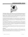
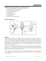
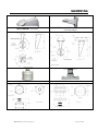
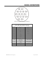
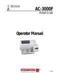
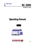
SIDEWINDER Series SW720A : 120VAC Installation Manual R0710 TABLE OF CONTENTS INFORMATION ……………………………………………………………… Page 3 PRODUCT WARRANTY & REPAIR …………………………………………. Page 4 SIDEWINDER SERIES: SW720A …………………………………………… Page 6 SAFEGUARDS, TOOLS & INSTALLATION ………………………………… Page 7 MOUNTING …………………………………………………………………. Page 8 SIGNAL CONNECTIONS …………………………………………………… Page 10 SEALING & PRESSURIZATION ……………………………………………. Page 14 TECHNICAL SPECIFICATIONS ……………………………………………. ©WTI (Wireless Technology, Inc.) : Sidewinder Page 16 Page 2 of 17 INFORMATION FCC NOTICE This device complies with Part 15 of the FCC Rules. Operation is subject to the following two conditions: 1.) This device may not cause harmful interference. 2.) This device must accept any interference that may be received, including interference that may cause undesired operation. READ THIS MANUAL Every effort has been made to insure that this WTI system is of the highest quality. This product has been carefully inspected to comply with rigid quality standards before shipment to you. In consideration of your investment and the desire to obtain full performance capability engineered into your new WTI product, we recommend that you read this manual before attempting to operate your system. FOR MORE ASSISTANCE OR MORE INFORMATION WTI (Wireless Technology, Inc.) 2064 Eastman Avenue, Suite 113 Ventura, CA 93003-7787 TOLL FREE. 866/gotowti (468-6984) TEL. 805/339-9696 FAX. 805/339-0932 EMAIL: [email protected] INTERNET: http://www.gotowti.com http://www.wirelesstech.com The software / firmware furnished with the equipment is confidential to and is copyrighted by Wireless Technology, Inc. (WTI) It is not to be copied or disclosed in any manner without the consent of Wireless Technology, Inc. (WTI). The software/firmware is furnished to the purchaser under a license for use on a single system. Information furnished by Wireless Technology, Inc. (WTI) is believed to be accurate and reliable. However, no responsibility is assumed by Wireless Technology, Inc. (WTI) for its use or for any infringements of other rights of third parties, which may result from its use. No license is granted by implications or otherwise under any patent or patent rights of Wireless Technology, Inc. (WTI) ©2010 Wireless Technology, Inc. (WTI) All rights reserved. ©WTI (Wireless Technology, Inc.) : Sidewinder or Page 3 of 17 PRODUCT WARRANTY AND REPAIR PRODUCT WARRANTY We appreciate your purchase of Wireless Technology, Inc. (WTI) security products. We take pride in the quality of our products and have manufactured each new WTI product to exacting quality standards. In normal use, it will provide you with years of satisfactory performance. However, should you experience difficulty; you are protected under the provisions of this warranty. WTI warrants to the original user a product that is free of defects in materials and workmanship in normal use. WTI warrants to the original user that WTI’s products will be free of defects in materials and workmanship in normal use for a period of 12 months from the date of sale. WTI’s obligation under this warranty shall be limited to the repair, including all necessary parts and the cost of labor connected therewith, or at our option, the replacement of any product that shows evidence of a manufacturing defect within the warranty period. This warranty is extended to all WTI products purchased and used within the United States of America and is valid only when service is rendered by the authorized WTI (Wireless Technology, Inc.) Warranty Station. This warranty shall not apply to appearance or accessory items including, but not limited to, knobs, connectors, cabinets and connecting cables. This warranty shall not, in addition, apply to repairs or replacements necessitated by any cause beyond the control of WTI including, but not limited to, acts of nature, improper installation, misuse, lack of proper maintenance, accident, voltage fluctuations, unauthorized repairs or modifications. This warranty becomes void in the event serial numbers are altered, defaced or removed, or an attempt is made to field service or alter performance of any WTI products. WTI reserves the right to make changes in design, or to make additions to, or improvements upon, products without incurring any obligation to install the same on products previously manufactured. The foregoing is in lieu of all other warranties expressed or implied and WTI neither assumes nor authorizes any person to assume for it any other obligation or liability in connection with the sale of our products. In no event shall WTI or its Authorized Dealers be liable for special or consequential damage arising from the use of this product, or any delay in the performance of this warranty due to causes beyond its control. ©WTI (Wireless Technology, Inc.) Page 4 of 17 PRODUCT WARRANTY AND REPAIR REPAIR AUTHORIZATION Please contact Wireless Technology, Inc. (WTI), to obtain a repair authorization number (RA) and provide the following information: 1.) Product Model & Serial Numbers. 2.) Date of shipment, purchase order number, sales order number or WTI invoice number. 3.) Details of the defect or malfunction. If there is a dispute regarding the warranty or product, which does not fall under the warranty conditions stated within the description of the written warranty, please include a written explanation with the product when returned. SHIP FREIGHT PRE-PAID TO: WTI (Wireless Technology, Inc.) 2064 Eastman Avenue, Suite 113 Ventura, CA 93003-7787 TEL 805/339-9696 FAX 805/339-0932 RETURNS No unauthorized returns will be accepted. All returns must have an authorized (RA) number issued by the factory (CA number if returned for credit and RA number if returned for repair). Products returned for repair or credit will be rejected if no authorization number has been issued or freight has not been pre-paid. All merchandise returned for credit will be subject to a 20% restocking and refurbishing charge. ©WTI (Wireless Technology, Inc.) Page 5 of 17 SIDEWINDER SERIES: SW720A The Sidewinder SW720A is a pan-tilt-zoom camera system that provides day/night color or black and white standard definition NTSC (PAL optional) video. The day/night feature can be set for manual or automatic operation. The camera provides 360 degree rotation in both the pan and tilt axes, and provides an optical zoom magnification of 35 times. A self-cleaning hydrophilic coating is provided on the front lens window of the camera to ensure clear, crisp video images and to reduce maintenance. An Indium-Tin-Oxide coating is provided on the inside of the front lens window to heat it and prevent fogging. The Sidewinder SW720A camera operates on AC line voltages within a voltage range of 85VAC to 265VAC and an operating frequency of 47Hz to 63Hz. All camera signals, including power, communication and video, are provided on a 16 pin circular plastic connector or an18 pin circular MS style connector mounted at the end of a 36 inch umbilical cable exiting from the bottom of the camera. The Sidewinder SW720A camera uses a 4 wire full duplex RS-485 or RS-422 compatible communication link to provide pan-tilt-zoom control and to allow setting of all of the presets, tours and other camera features. While basic pan-tilt-zoom operation can be implemented with only a two wire uni-directional interface, it is recommended that the camera be provided with the full 4 wire interface to enable the more advanced features, such as remote firmware uploading and camera status queries. The SW720A camera supports industry standard COHU and Pelco setup and command codes sets. NTCIP Code support can be provided as an option. Please contact the factory for code support information. Unpacking Please examine the equipment carefully when unpacking the shipping container. If any damage is noted please be sure to file a claim with the carrier. WTI is not responsible for any damage that occurs during shipping. Please verify that all of the contents are present and carefully check the packing material for any loose items before recycling it. ©WTI (Wireless Technology, Inc.) Page 6 of 17 SAFEGUARDS, TOOLS & INSTALLATION Safeguards 1.) Read Instructions. It is important to read all safety and operating instructions before installing or using this equipment. 2.) Retain Instructions. Retain this manual and any supplements for future reference. 3.) Follow Instructions. Follow all instructions herein for use of this equipment. 4.) Heed all warnings. Adhere to all warnings on the equipment, and in this manual. 5.) To reduce the risk of electric shock or equipment damage, work on the unit only when the power is shut off and is unplugged from its power source to prevent accidental activation. Also take precautions to avoid contact between the equipment and other electrical wires or power sources that may be present at the installation site. 6.) Some internal components of this camera are static sensitive. When performing work on the inside of the camera unit, work only at an approved static free work station. Recommended tools and accessories for proper installation 1.) Tie wraps to secure cable runs. 2.) Set of open end and socket wrenches. 3.) Cordless power drill. 4.) Safety cable recommended (prevents camera falling during overhead installations). 5.) Self-sealing connector tape to weatherproof all cable connections. Installation planning 1.) The maximum cable length that should be planned for is 750 feet. This is primarily a limitation related to achieving acceptable video quality. Excessively long video runs will not have crisp detail in the images, due to the high frequency roll off of the long video cable. 2.) The Sidewinder SW720A camera draws up to 50 Watts maximum, which translates to about 0.59 Amps at the low line voltage limit of 85VAC. This will result in an AC Line voltage drop of no more than 6VAC over the maximum 750 foot umbilical cable run. 3.) Be sure to verify that there are no physical obstructions that might prevent the camera from turning freely in all directions. 4.) Be sure to verify that there are no physical obstructions in the way of any required viewing directions. 5.) If at all possible, utilize all 4 bi-directional interface connections, rather than a simpler 2 conductor unidirectional interface. This will allow field firmware updates without having to dismount the camera and can provide valuable troubleshooting information in the case of any problems that might be encountered during the installation process. Equipment supplied with unit ~Camera ~4 each ¼-20 x ¾” mounting screws ~Manual ©WTI (Wireless Technology, Inc.) Page 7 of 17 MOUNTING Equipment that may be required but not supplied with unit 1.) Mating connector and strain relief for umbilical cable 2.) 11 contact pins for mating connector 3.) Crimping tool for connector pins 4.) Camera mounting bracket 5.) Interconnect cables 6.) Video monitor 7.) PC or laptop computer 8.) Setup software 9.) Local rack mount control panel Mechanical dimensions Mounting The Sidewinder SW720A camera should normally be mounted in an upright orientation, as shown in the drawing above. The camera may also be mounted upside down if desired, but a cover of some sort should be placed over the bottom of the camera, extending out to about 6 inches past the camera all around, to prevent debris, dirt or snow and ice from accumulating on the bottom of the camera housing, since the conical shaped profile of the camera will no longer be able to naturally shed material to the sides. The camera may NOT be mounted with the base facing horizontally. The base of the Sidewinder SW720A camera has four ¼-20 screw holes that are equally spaced, 90° apart, on a 4.75” diameter circle. If mounting screws other than those provided with the camera are used, the length of the mounting screws should be selected so that the screws penetrate no more than 0.75 inches into the base. WTI manufactures several different mounts for the Sidewinder SW720A that allow the camera to be attached to pole tops, horizontal poles, vertical poles and walls (see the following table for more information). ©WTI (Wireless Technology, Inc.) Page 8 of 17 MOUNTING Model #SWWM1: Wall Mount Model #SWWM1 and #SWVPA: Wall Mount with Vertical Pole Mount Adapter Model #SWPTM1: Post Top Mount Model #SWHPM1: Horizontal Pole Mount ©WTI (Wireless Technology, Inc.) Page 9 of 17 SIGNAL CONNECTIONS The Sidewinder SW720A camera is supplied with a 36 inch umbilical cable to allow the cable to be routed through the camera mount before the actual physical installation of the camera. Signal Connections The Sidewinder SW720A is provided with a 36 inch umbilical cable and is available with either an AMP 16 pin circular plastic connector or an 18 pin MS Style connector at the end. The umbilical cable provides the power, video and control data signal connections for the camera. The umbilical cable is also available with the cable stripped and tinned, instead of with the 16 pin circular connector. The umbilical cable exits through the bottom of the camera housing. The connector pin outs and umbilical cable wire color code are as follows: ©WTI (Wireless Technology, Inc.) Page 10 of 17 SIGNAL CONNECTIONS AMP 16 pin circular connector pin arrangement 16 Pin AMP Cable Pin/Wire Functions Pin/Wire 1 2 3 4 5 6 7 8 9 10 11 12 13 14 15 16 ©WTI (Wireless Technology, Inc.) Signal Video Video Ground Data Ground TxTx+ Rx+ RxN/C N/C N/C N/C 85-265 AC Line Input (high/hot) AC Line Neutral (low) Cable Shield 115 VAC Ground N/C Color RG-59 Center RG-59 Shield Data Shield Green White Red Black --------------------18AWG Black 18AWG White Overall Shield 18AWG Green ------ Page 11 of 17 SIGNAL CONNECTIONS MS 18 pin circular connector pin arrangement 18 Pin MS Cable Pin/Wire Functions Pin/Wire A B C D E F G H J K L M N P R S T U ©WTI (Wireless Technology, Inc.) Signal Video Ground N/C N/C N/C N/C N/C 115 VAC Ground Cable Shield N/C N/C Video Rx+ RxData Ground TxTx+ AC Line Neutral (low) 85-265 AC Line Input (high/hot) Color RG-59 Shield -------------------------18AWG Green Overall Shield ----------RG-59 Center Red Black Data Shield Green White 18AWG White 18AWG Black Page 12 of 17 SIGNAL CONNECTIONS AC Line Connections The AC Line connections should be connected to an AC mains source with a voltage of 85VAC to 265VAC, operating at a frequency of 47Hz to 63Hz. The nominal operating voltage is normally 115VAC or 230VAC. The camera draws 50 Watts maximum, which translates to about 0.6 Amps at the worst case low line voltage of 85VAC. The “hot” side of the AC mains connections should applied to pin 12 of the circular plastic connector, Pin U of the 18 pin MS connector or to the black #18 AWG conductor if a stripped and tinned pigtail is being used. The “low” side of the AC mains connections should applied to pin 13 of the circular plastic connector, Pin T of the 18 Pin MS connector or to the white #18 AWG conductor if a stripped and tinned pigtail is being used. The AC mains safety ground connection should applied to pin 15 of the circular plastic connector, Pin G of the 18 Pin MS connector or to the green #18 AWG conductor if a stripped and tinned pigtail is being used. Video Connections The video signal connections provide a standard 1Vpp NTSC (or PAL) video signal with a 75Ω drive impedance. The center conductor of the RG-59 video cable is connected to pin 1 of the circular connector or to Pin L of the 18 Pin MS connector. The shield of the RG-59 video cable is connected to pin 2 of the circular connector or to Pin A of the 18 Pin MS connector. In the case of units with a stripped and tinned umbilical cable, the video cable will be terminated with a male BNC connector. Data connections Communications with the Sidewinder SW720A are provided through the TX+, TX-, RX+ and RX- signals which are RS-485 compatible and support multiple cameras on the same communication segment. The RX+ and RX- signals are the camera data input lines that receive data from the pan-tiltcontroller. These lines are required for all applications. The TX+ and TX- signals are signal driving lines that send data from the camera back to the pan-tilt-zoom controller. These lines are required for certain control software programs to provide command acknowledgements and to provide handshake signals for remote firmware upgrades. ©WTI (Wireless Technology, Inc.) Page 13 of 17 SEALING & PRESSURIZATION There are internal 120Ω termination resistors for both the TX and RX signal pairs that may be enabled or disabled through the use of the WTI HHC-SW hand held controller unit. The factory shipped default state for the 120Ω terminations is for both the TX and RX terminations to be enabled. Applications that involve multiple cameras on the same RS-485 communications lines will require that the terminations on all cameras but one be turned off. Note that COHU code does not support software switching of the RS-485 terminations. To operate the Sidewinder SW720A camera using RS-232 control signals, an RS-232 to RS-485 or RS-422 adapter should be used. Surge Protection The Sidewinder SW720A camera provides internal surge protection for all of the power, data and video signals. 1.) The AC line power connections are provided with 275 volt 135 Joule MOV surge arrestors rated for 6000 Amp pulses. A 3A slo-blo SMT fuse is included in the primary circuit to prevent catastrophic printed circuit board damage in the case of gross AC line input overloads. 2.) The video signal lines incorporate a two stage protection circuit consisting of a primary 90V gas discharge tube, followed by a high speed, low capacitance 6.2V 2kW peak power transient voltage suppressor. 3.) The data signal lines incorporate a two stage protection circuit consisting of a primary 90V gas discharge tube, followed by an 18V, 300W, 40A transient voltage suppressor. Sealing and Pressurization – Camera Backplate The Sidewinder SW720A camera provides two levels of sealing and pressurization. The entire camera, including the base, housing and camera tube are all sealed to IP66/67 levels to prevent any ingress of dust or moisture. In addition, the camera housing tube is pressurized to at least 5 psi with dry nitrogen gas. ©WTI (Wireless Technology, Inc.) Page 14 of 17 SEALING & PRESSURIZATION The Sidewinder SW720A camera is provided with a Schrader valve to allow periodic replenishment of the dry Nitrogen in the camera housing tube. Since no sealing system will remain 100% airtight indefinitely, it may be necessary to replenish the dry Nitrogen occasionally. This can be done at the same time that the regular camera cleaning is performed. A 15psi pressure relief safety valve is provided to prevent damage to the seals and to prevent blowing out the front or back plates of the camera housing if an unregulated high pressure dry Nitrogen tank were to be connected to the Schrader valve. The camera housing tube pressure may be displayed using the COHU command provided for this query function or with the use of COHU camera setup software. The camera housing tube pressure value is derived from an absolute pressure sensor in the tube, and is corrected for both temperature and altitude. A user adjustable altitude setting is provided that may be set from 0 to 10,000 feet. An on screen low pressure alert is displayed when the pressure variable reads lower than 1 psi. Increasing the altitude setting above 0 will increase the pressure variable value, since the lower pressure at higher altitudes would increase the internal to external pressure differential. The absolute pressure reading from the pressure sensor in the camera housing tube is normalized to 0psi at sea level at 20° Celsius (14.7psi). So, if the camera is completely depressurized at sea level, and the altitude variable is set for 0, at 20° Celsius the pressure variable will read approximately 0psi. Note that the camera housing temperature will be 10 to 15° higher than the ambient temperature after the camera has been turned on for a while. The pressure reading is also corrected for temperature, so that if the camera tube temperature goes up or down, the pressure reading will remain constant (after the temperature has stabilized). Otherwise, a situation would arise where the pressure would read lower at night, when it is cooler, than it would during the day, when it is warmer. This could lead to intermittent pressure alarm condition warnings. Camera temperature and pressure readings are updated at ten minute intervals and are averaged over ten readings. Code Support The SW720A Sidewinder camera supports COHU, Pelco D and Pelco P code. Optional support is available for NTCIP code when using the SWRCU Rack Control Unit. Setup Software The SW720A Sidewinder camera is fully compatible with COHU WinMPC setup software, in order to provide compatibility with existing installations. ©WTI (Wireless Technology, Inc.) Page 15 of 17 TECHNICAL SPECIFICATIONS: SW720A Camera Mechanical Imager Resolution ¼” color progressive scan, interline transfer CCD NTSC or PAL, 520 horizontal TV lines Weight 15.3 lbs. (7.0 kgs.) Vibration (less lens) 3g (rms) random, 5 to 1000 Hz, any axis Withstands exposure to sand, dust, fungus, salt atmosphere, per MIL-E5400T, paragraph 3.2.24.7, 3.2.24.8 and 3.2.24.9 Effective Pixels NTSC @ 768 x 494, PAL @ 768 x 582 Air Contaminants Lens High durability 35X optical zoom, F1.4 with 12X digital zoom Positioner Lens Horizontal Angle of View 55.8° w, 1.7° t Pan / Tilt Drive Pan Angle Range: Continuous 360° Tilt Angle Range: Continuous 360° Pan Speed: 100°/sec – proportional to zoom Tilt Speed: 50°/sec – proportional to zoom Pan/Tilt Encoder Resolution: 0.01° Pan/Tilt Repeatability: 0.05° On/off Sector Zones Up to 16 in the horizontal plane Wide Dynamic Range EIS @ 5 Hz Suppression Focal Length -12 dB @ 5 Hz Privacy Zones 3.4mm ~ 120mm S/N Ratio >50 dB Iris Auto or manual override Preset Title Generation Compass / Position White Balance Auto or manual Tours Shutter Auto or manual override Focus Auto or manual override Communications Communication RS-422 or RS-485 standard / Physical Layer Sync IR Cut Filter Internal Auto or manual (on/off) 0.5 Lux typical down to 0.01 Lux in IR mode Sensitivity Electrical Power Input 85 – 265 VAC Power Consumption (with heater on) 50W Power Transients / Interruptions Conforms to NEMA TS2, paragraph 2.1.6 Protocol Cohu, Pelco or optional NTCIP Firmware Field upgradable flash memory Environmental Ambient Temperature Limit -29° F to +165° F (-34° C to +74° C); Conforms to NEMA 2.1.5.1 standard TS2 for traffic control systems Humidity 100% relative humidity Protection Rating Shock ©WTI (Wireless Technology, Inc.) 8 programmable zones can be set for video blanking 64 preset positions 5 lines of 24 characters for camera ID and preset ID 1 line, includes compass direction and absolute setting 8 tours of 32 presets with individual dwell settings per preset IP66 and NEMA 4X; camera housing sealed and pressurized to 5 PSI (34 kPa) with dry nitrogen. IP67 pan/tilt assembly. Conforms to NEMA TS2, paragraph 2.2.10 Page 16 of 17 Wireless Technology, Inc. (WTI) 2064 Eastman Avenue, Suite 113 Ventura, CA 93003-7787 USA tel 805/339-9696 fax 805/339-0932 email: [email protected] www.gotowti.com www.wirelesstech.com Due to Wireless Technology, Inc. (WTI) continuing efforts to engineer the best product that is most responsive to our customer’s needs, the above specifications are subject to change without notice. ©WTI (Wireless Technology, Inc.) Page 17 of 17