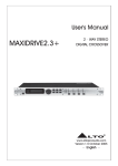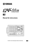
1
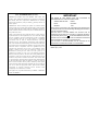
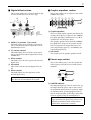
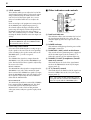
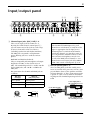
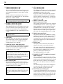
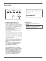
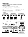
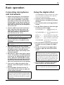
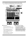
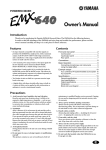
Owner’s Manual
INPUT
MIC
MIC
MIC
OUTPUT
MIC
MIC
MIC
MIC
MIC
9L
B
REC
–10dBV
TAPE
10 R
LINE
LINE
LINE
LINE
LINE
LINE
LINE
R
12 R
B
LINE
11 L
L
R
ST 2
(MONO)
(MONO)
R
ST
SUB 1
R
ST
SUB 2
+4dB
+4dB
MONO
+4dB
+4dB
MONI
1
L
L
(MONO)
A
R
ST 1
+4dB
R
B
9L
(MONO)
A
FOOT SW
L
L
L
11 L
B
MONI
2
EFFECT
+4dB
+4dB
INS
I/O
INS
I/O
INS
I/O
INS
I/O
1
2
3
4
5
GAIN
GAIN
GAIN
GAIN
GAIN
0dB
INSERT I/O
OUT IN
10 R
12 R
A
6
7
8
GAIN
GAIN
GAIN
A
9/10
11/12
A
B
A
B
GAIN
GAIN
L
R
PAMP
IN
PHONES/
C-R OUT
(+4dB)
+4dB
BRIDGE
TAPE IN
L POWER AMP R
LIMITER
PEAK
+8
ST
MONI 1
–34
+10
–34
PEAK
HIGH
0
0
10
+15
MID
–15
+15
MID
–15
+15
MID
–15
+15
MID
–15
+15
MID
–15
+15
MID
–15
+15
MID
–15
+15
MID
–15
+15
MID
–15
+15
MID
0
10
0
10
PHANTOM
(+48V)
0
ST R
MONO
ON
–1
OFF
–3
MONO BRIDGE
–5
MONI 2
MONI 1
ST
+3
+4
+1
ST L
MONI 1
MONI 2
PFL
–15
+18
+18
+4
L/BRIDGE
10
POWER
+5
LEVEL
+10
–34
+10
–34
+10
–34
+10
–34
+10
–34
+10
–34
+10
–34
+10
–34
+10
–16
–16
–16
–16
–16
–16
–16
–16
–60
–60
–60
–60
–60
–60
–60
–60
PEAK
PEAK
PEAK
PEAK
PEAK
PEAK
PEAK
PEAK
PEAK
HIGH
HIGH
HIGH
HIGH
HIGH
HIGH
HIGH
HIGH
HIGH
EEEngine
ST
PHONES/C.R.OUT
–7
–10
–15
+15
LOW
–15
+15
LOW
–15
+15
LOW
–15
+15
LOW
–15
+15
LOW
–15
+15
LOW
–15
+15
LOW
–15
+15
LOW
–15
+15
LOW
–15
+15
0
10
0
10
0
–15
10
PFL
L
ON
DIGITAL EFFECT
–15
+15
MONI 1
–15
+15
MONI 1
–15
+15
MONI 1
–15
+15
MONI 1
–15
+15
MONI 1
–15
+15
MONI 1
–15
+15
MONI 1
–15
+15
MONI 1
–15
+15
MONI 1
0
–20
LOW
–15
ST SUB 1
+15
MONI 1
MONI 1
6
7 8 9
5
4
3
0
MONI 2
10
0
MONI 2
10
0
MONI 2
10
0
MONI 2
10
0
MONI 2
10
0
MONI 2
10
0
MONI 2
10
0
MONI 2
10
0
MONI 2
10
0
MONI 2
10
0
EFFECT
10
0
EFFECT
10
0
EFFECT
10
0
EFFECT
10
0
EFFECT
10
0
EFFECT
10
0
EFFECT
10
0
EFFECT
10
0
EFFECT
10
0
EFFECT
10
0
MONI 2
10
2
1 16 15
PROGRAM
10
11
12
13
14
125
0
10
0
10
ST
MIN
0
MAX
5 VOCAL REVERB 1 9 HALL 1
13 PLATE 1
2 VOCAL ECHO 2
6 VOCAL REVERB 2 10 HALL 2
14 PLATE 2
3 VOCAL ECHO 3
7 VOCAL REVERB 3 11 HALL 3
15 PLATE 3
8 VOCAL REVERB 4 12 ROOM
16 GATE REVERB
4 VOCAL ECHO 4
250
500
1k
2k
4k
8k
+12
+12
6
0
10
PAN
0
10
PAN
0
10
PAN
0
10
PAN
0
10
PAN
0
10
PAN
0
10
PAN
0
10
PAN
0
10
BAL
0
10
BAL
10
1 VOCAL ECHO 1
6
0
10
ST 2
R
ST1
0
6
6
–12
–12
ON
PFL
GRAPHIC EQUALIZER
L
L
R
PFL
L
R
PFL
L
R
PFL
L
R
PFL
L
R
PFL
L
R
PFL
L
R
PFL
L
R
PFL
L
R
PFL
R
ST SUB 2
PFL
AFL
AFL
AFL
AFL
AFL
0
0
0
0
0
0
0
0
0
0
0
0
0
0
0
5
10
5
10
5
10
5
10
5
10
5
10
5
10
5
10
5
10
5
10
5
10
5
10
5
10
5
10
5
10
15
15
15
15
15
15
15
15
15
15
15
15
15
15
15
20
20
20
20
20
20
20
20
20
20
20
20
20
20
20
25
30
40
50
25
30
40
50
25
30
40
50
25
30
40
50
25
30
40
50
25
30
40
50
25
30
40
50
25
30
40
50
25
30
40
50
25
30
40
50
25
30
40
50
25
30
40
50
25
30
40
50
25
30
40
50
25
30
40
50
∞
∞
1
∞
2
∞
3
∞
4
∞
5
∞
6
∞
7
∞
8
∞
9/10
∞
11/12
∞
MONI 1
∞
MONI 2
∞
EFFECT
∞
ST 1
MONO
E
FCC INFORMATION (U.S.A.)
1. IMPORTANT NOTICE: DO NOT MODIFY THIS UNIT! This
product, when installed as indicated in the instructions contained in
this manual, meets FCC requirements. Modifications not expressly
approved by Yamaha may void your authority, granted by the FCC, to
use the product.
2. IMPORTANT: When connecting this product to accessories and/or
another product use only high quality shielded cables. Cable/s supplied
with this product MUST be used. Follow all installation instructions.
Failure to follow instructions could void your FCC authorization to use
this product in the USA.
3. NOTE: This product has been tested and found to comply with the
requirements listed in FCC Regulations, Part 15 for Class “B” digital
devices. Compliance with these requirements provides a reasonable
level of assurance that your use of this product in a residential
environment will not result in harmful interference with other
electronic devices. This equipment generates/uses radio frequencies
and, if not installed and used according to the instructions found in the
users manual, may cause interference harmful to the operation of other
electronic devices. Compliance with FCC regulations does not
guarantee that interference will not occur in all installations. If this
product is found to be the source of interference, which can be
determined by turning the unit “OFF” and “ON”, please try to
eliminate the problem by using one of the following measures:
Relocate either this product or the device that is being affected by the
interference. Utilize power outlets that are on different branch (circuit
breaker or fuse) circuits or install AC line filter/s. In the case of radio
or TV interference, relocate/reorient the antenna. If the antenna lead-in
is 300 ohm ribbon lead, change the lead-in to coaxial type cable. If
these corrective measures do not produce satisfactory results, please
contact the local retailer authorized to distribute this type of product. If
you can not locate the appropriate retailer, please contact Yamaha
Corporation of America, Electronic Service Division, 6600
Orangethorpe Ave, Buena Park, CA 90620
This applies only to products distributed by YAMAHA CORPORATION OF AMERICA.
WARNING: THIS APPARATUS MUST BE EARTHED
IMPORTANT
THE WIRES IN THIS MAINS LEAD ARE COLOURED IN
ACCORDANCE WITH THE FOLLOWING CODE:
GREEN-AND-YELLOW :
EARTH
BLUE :
NEUTRAL
BROWN :
LIVE
As the colours of the wires in the mains lead of this apparatus may
not correspond with the coloured markings identifying the terminals in
your plug, proceed as follows:
The wire which is coloured GREEN and YELLOW must be
connected to the terminal in the plug which is marked by the letter E
or by the safety earth symbol
or coloured GREEN and YELLOW.
The wire which is coloured BLUE must be connected to the terminal
which is marked with the letter N or coloured BLACK.
The wire which is coloured BROWN must be connected to the
terminal which is marked with the letter L or coloured RED.
* This applies only to products distributed by YAMAHA KEMBLE
MUSIC (U.K.) LTD.
2
Introduction
Thank you for purchasing the Yamaha EMX2000 Powered Mixer. In order to take full
advantage of the EMX2000 and enjoy long, trouble-free performance, please read this
owner’s manual carefully, and keep it in a safe place for future reference.
Features
• The EMX2000 provides versatile inputs, such as
two stereo input channels and two stereo sub
inputs, as well as eight monaural input channels
compatible with mic/line signals. The mixer also
has ample power, with a maximum output of
200 W+200 W (400 W with bridge connection),
and is suitable for a wide range of applications
from installed systems to small-scale PA systems.
• A two-channel power amp is built-in. The signals
output to speakers can be selected as stereo main
(ST L-R), monitor+monaural main (MONI 1MONO), or monaural main (bridge connection).
– Stereo main
The main stereo mix signal is output from
speaker output jacks L and R of the EMX2000.
You can connect one or two speakers to each
speaker output jack.
– Monitor+monaural main
The main monaural mix signal is output from
speaker output jack R, and the monitor signal
from speaker output jack L. You can connect one
or two speakers to each speaker output jack.
– Monaural main (bridge connection)
The two-channel power amp is bridge-connected, and the main monaural mix signal is output from BRIDGE jack. You can connect only one
speaker for a much louder sound.
EMX2000—Owner’s Manual
• In addition to the speaker output jacks, two stereo output channels for line-level signals, two
monitor output channels, one effect output, and
one monaural output are provided. You can easily expand the system by adding a power amplifier or powered speakers.
• The EMX2000 also has a PHONES C-R OUT
jack, which is very useful for checking the sound.
You can monitor only a specific channel or bus
signal through the headphones.
• Two limiter circuits are built-in to prevent excessive input levels to the amp.
• A digital effect with sixteen selectable effect types
is built-in. A variety of effects can be applied to
add reverberation or ambience to vocals or
instrumental sounds.
• The EMX2000 has implemented “EEEngine”,
Yamaha’s epochal amp drive technology to create
an unrivaled high-efficiency drive.
The EEEngine’s energy-saver/low-heat-generation design has reduced power consumption to
50% or less, and reduced heat generation to 35%
or less (in field applications, compared to
Yamaha’s previous models), and has lead to a
reduction in energy cost and to less-restrictive
installation requirements related to heat generation.
3
Precautions
1. Avoid excessive heat, humidity, dust and
vibration
Keep the unit away from locations where it is
likely to be exposed to high temperatures or
humidity — such as near radiators, stoves, etc.
Also avoid locations which are subject to excessive dust accumulation or vibration which could
cause mechanical damage.
2. Ventilation
Allow a distance of 30 cm between the unit and
the wall so that heat generated from the unit will
be released effectively. Also, allow enough space
between the unit and other devices. If you mount
the unit in an audio rack, keep a space of 40 cm
on the top panel, and a space of 15 cm to the side
panel. Remove the rear panel of the rack or open
a vent hole. If heat release is inadequate, the unit
will retain heat inside the unit, which may cause a
fire.
3. Avoid physical shocks
Strong physical shocks to the unit can cause damage. Handle it with care.
4. Do not open the case or attempt repairs
or modifications yourself
This product contains no user-serviceable parts.
Refer all maintenance to qualified Yamaha service
personnel. Opening the case and/or tampering
with the internal circuitry voids the warranty.
5. Always power off before making connections
Always turn the power OFF before connecting or
disconnecting cables. This is important to prevent damage to the unit itself as well as other connected equipment.
6. Handle cables carefully
Always plug and unplug cables — including the
AC power cord — by gripping the connector, not
the cord.
7. Clean with a soft dry cloth
Never use solvents such as benzine or thinner to
clean the unit. Wipe clean with a soft, dry cloth.
8. Always use the correct power supply
Make sure that the power supply voltage specified
on the rear panel matches your local AC mains
supply. Also make sure that the AC mains supply
can deliver more than enough current to handle
all equipment used in your system.
9. Do not touch the heatsink when the
EMX2000 is in use. It can get very hot.
Contents
Front and rear panel................................ 4
Specifications......................................... 17
Control panel ...................................................4
General specifications.................................... 17
Input specifications ....................................... 18
Output specifications .................................... 18
Input/output panel.................................. 9
Rear panel.......................................................11
Connections........................................... 12
Connecting speakers......................................12
Connecting input/output equipment...........12
Dimensions............................................ 19
Block/Level Diagram............................. 20
Basic operation ...................................... 13
Connecting microphones and instruments .13
Using the digital effect ...................................13
Example setups ...................................... 14
As a band PA ..................................................14
As a conference/entertainment hall sound
system .............................................................15
Using a subwoofer .........................................16
EMX2000—Owner’s Manual
4
Front and rear panel
Control panel
■ Channel control section
In this section, you can adjust equalization (frequency response), volume level, effect and monitor output levels for the input signal of each
channel.
2
A
B
GAIN
GAIN
1
3
+10
–34
–16
–60
PEAK
HIGH
–15
+15
MID
1
+10
–34
3
PEAK
HIGH
–15
4
–15
+15
LOW
+15
LOW
–15
+15
MONI 1
5
–15
–15
+15
0
MONI 2
10
0
MONI 2
10
0
EFFECT
10
0
EFFECT
10
6
PAN
0
10
BAL
7
8
L
9
0
5
6
10
L
R
PFL
0
5
10
5
10
15
15
20
20
25
30
40
50
25
30
40
50
∞
R
PFL
0
9
0
9/10
1 GAIN control
Use this knob to adjust the sensitivity according
to the input signal level, so that the input level is
appropriate.
For the best balance of S/N ratio and dynamic
range, adjust this knob so that the peak indicator
3 lights occasionally.
EMX2000—Owner’s Manual
This is a 3-band equalizer that adjusts the high
frequency range, mid frequency range, and low
frequency range of each channel. Response is flat
when the knobs are in the “▼” position. Rotating
it toward the right will boost the corresponding
frequency band, and rotating it toward the left
will cut it.
The base frequency (or center frequency), range
of boost or cut, and equalizer type of each band
are as follows:
HIGH: 10kHz, ±15 dB, shelving type
MID: 2.5kHz, ±15 dB, peaking type
LOW: 100Hz, ±15 dB, shelving type
5 Monitor 1/2 controls (MONI 1/2)
∞
1
The indicator will light 3 dB before clipping,
warning that clipping level is near.
4 Equalizer controls (HIGH, MID, LOW)
MONI 1
0
This switch selects channel 9/10~11/12 connectors.
When the switch is up, the signal will be input
from connectors A (phone jacks on the input/
output panel 3).
When the switch is pressed in, the signal will be
input from connectors B (phono jacks on the
input/output panel 3).
3 PEAK indicator
+15
MID
4
2 A/B switch (Channels 9/10~11/12 only)
For each channel, this controls the amount of signal that is sent to the MONITOR 1/2 buses.
The signal of the MONITOR 1 bus is sent to the
MONI 1 jack (input/output panel 9). If the
power amp select switch V is in the MONI 1MONO position, the signal is also sent to the
speakers connected to the SPEAKERS L1/2 jacks.
The signal of the MONITOR 2 bus is sent to the
MONI 2 jack (input/output panel 9).
Note: The signal sent to the MONITOR 1/2
buses does not pass through the channel fader
0 (pre-fader send). This means that it will not
be affected by the setting of the channel fader.
5
6 Effect control (EFFECT)
For each channel, this controls the amount of signal that is sent to the EFFECT bus.
The signal of the EFFECT bus is sent to the
EFFECT jack (input/output panel A). It is also
sent to the built-in effect when the ON switch P
in the EFFECT section is turned on.
■ Stereo sub input section
In this section, you can adjust the input level of
external equipment connected to the ST SUB 1/2
jacks on the input/output panel.
MONI 1
A
0
Note: The amount of signal that is sent to the
EFFECT bus from each channel will be affected not only by the setting of the EFFECT control, but also by the setting of the channel fader
0 (post-fader send).
7 PAN (panpot) control (Channels 1~8)
The PAN knobs set the stereo position of the signal that is sent to the STEREO bus.
8 BAL (balance) control (Channels 9/10~
11/12)
The BAL knobs set the balance between the left
and right channels, and assign the signals
received at inputs 9/10~11/12 to the STEREO
bus.
9 PFL (pre-fader listen) switch
When the PFL switch is turned on, the signal of
the corresponding channel at the point after the
equalization but before the channel fader is sent
to the PHONES/C-R OUT jack (input/output
panel B). This is useful when you wish to listen
to a particular channel through the headphones.
Note: You can monitor the signal through the
headphones even if the fader of the corresponding channel is set to the lowest level. The
switch operation does not affect the signal sent
to the STEREO bus, MONITOR 1/2 buses, or
the EFFECT bus.
0 Channel fader
This controls the output level of the input channel signal.
10
MONI 2
B
0
10
0
10
ST
C
D
PFL
ST SUB 1
MONI 1
A
0
MONI 2
10
B
0
10
0
10
ST
C
PFL
D
ST SUB 2
A MONI 1 (monitor 1) control
The MONI 1 knob adjusts the amount of the signal sent from the ST SUB 1 and 2 jacks (input/
output panel 4) to the MONITOR 1 bus.
B MONI 2 (monitor 2) control
The MONI 2 knob adjusts the amount of the signal sent from the ST SUB 1 and 2 jacks to the
MONITOR 2 bus.
C ST (stereo) control
The ST knob adjusts the amount of stereo signal
sent from the ST SUB 1 and 2 jacks to the STEREO bus.
Note: The ST control setting does not affect
the level of the signal sent to the MONITOR
1/2 buses (pre-fader send).
D PFL (pre-fader listen) switch
When this switch is turned on, the signal at the
point before the ST control knob C is sent to the
PHONES/C-R OUT jack (input/output panel
B).
EMX2000—Owner’s Manual
6
■ Master control section
I MONO (monaural) fader
In this section, you can adjust the final level of
the outputs.
AFL
AFL
AFL
AFL
AFL
0
0
0
0
0
5
10
5
10
5
10
5
10
5
10
15
15
15
15
15
20
20
20
20
20
25
30
40
50
25
30
40
50
25
30
40
50
25
30
40
50
25
30
40
50
∞
∞
∞
∞
J
The MONO fader adjusts the final level of the
monaural signal output from the STEREO bus to
the MONO jack (input/output panel 0).
If the Power amp select switch V is set to
MONI 1-MONO, this fader also adjusts the level
of the signal sent from the SPEAKERS R 1/2 jacks
to the speakers.
If the Power amp select switch V is set to MONO
BRIDGE, this fader adjusts the level of the signal
sent from the SPEAKERS BRIDGE jack to the
speaker.
J AFL (after fader listen)
∞
MONI 1
MONI 2
EFFECT
ST 1
MONO
E
F
G
H
I
E MONI 1 (monitor 1) fader
The MONI 1 fader adjusts the final level of the
signal sent from the MONITOR 1 bus to the
MONI 1 jack (input/output panel 9). If the
Power amp select switch V is set to MONI 1MONO, using this fader enables you to adjust the
level of the signal sent from the SPEAKER L 1/2
jacks to the speakers.
F MONI 2 (monitor 2) fader
The MONI 2 fader adjusts the final level of the
signal output from the MONITOR 2 bus to the
MONI 2 jack (input/output panel 9).
When this switch is on, the output signal that
passes through the corresponding fader is sent to
the PHONES/C-R OUT jack (input/output panel
B). Use these switches when you wish to monitor a particular output signal through the headphones.
■ Tape in section
In this section, you can adjust the input level of a
cassette deck or a CD player that is connected to
the TAPE jacks (input/output panel 5).
TAPE IN
ST
K
0
10
PFL
L
G EFFECT fader
The EFFECT fader adjusts the final level of the
signal output from the EFFECT bus to the
EFFECT jack (input/output panel A).
Note: The setting of this fader does not affect
the level of the signal sent from the EFFECT
bus to the built-in effect.
H ST 1 (stereo 1) fader
The ST 1 fader adjusts the final level of the signal
sent from the STEREO bus to the ST 1 jacks
(input/output panel 8). If the Power amp select
switch V is set to ST L-ST R, this fader also
adjusts the level of the signal sent to the SPEAKERS jacks (rear panel 1).
Note: The setting of this fader does not affect
the signal output from the STEREO bus to the
ST 2 jacks.
EMX2000—Owner’s Manual
K ST (stereo) control
This knob adjusts the level of the signal sent from
the TAPE jacks to the STEREO bus.
L PFL (pre-fader listen) switch
When this switch is on, the signal input from the
TAPE jacks is routed at the point before the ST
control to the PHONES/C-R OUT jack (input/
output panel B).
7
■ Digital effect section
■ Graphic equalizer section
This section enables you to turn the built-in digital effect on/off and select the effect type.
M
MONI 1
10
125
N
MONI 2
0
0
ST
10
0
10
ON
DIGITAL EFFECT
6
7 8 9
5
4
3
2
1 16 15
PROGRAM
10
11
12
13
14
This section enables you to adjust the tone of the
STEREO bus signal.
MIN
P
Q
250
500
1k
2k
4k
8k
+12
+12
6
6
0
0
6
6
–12
–12
R
ON
S
GRAPHIC EQUALIZER
MAX
1 VOCAL ECHO 1
5 VOCAL REVERB 1 9 HALL 1
13 PLATE 1
2 VOCAL ECHO 2
6 VOCAL REVERB 2 10 HALL 2
14 PLATE 2
3 VOCAL ECHO 3
7 VOCAL REVERB 3 11 HALL 3
15 PLATE 3
4 VOCAL ECHO 4
8 VOCAL REVERB 4 12 ROOM
16 GATE REVERB
O
M MONI 1/2 (monitor 1/2) control
This knob adjusts the level of the return signal
that is sent from the built-in digital effect to the
MONITOR 1/2 buses.
N ST (stereo) control
This knob adjusts the level of the return signal
that is sent from the built-in digital effect to the
STEREO bus.
O Effect selector
This knob selects the effect type for the internal
digital effect.
P ON switch
This switch turns the internal digital effect on/
off.
Q Effect control
This knob adjusts the time parameter of the
internal digital effect.
Note: The master EFFECT fader setting does
not affect the internal digital effect signal.
R Graphic equalizer
This is a 7-band graphic equalizer that allows you
to adjust the frequency response of the STEREO
bus signal, providing a maximum of ±12 dB of
cut/boost for each frequency band.
This graphic equalizer affects both the STEREO
bus signal that is output to the speakers and the
line level signal that is output from the ST 1/2
jacks (input/output panel 8), and MONO jack
(input/output panel 0).
S ON switch
This switch turns the graphic equalizer on/off.
■ Power amp section
This section allows you to select the signals that
will be input to the built-in two-channel power
amplifier.
L POWER AMP R
LIMITER
T
U
LEVEL
+18
+4
L/BRIDGE
+18
ST L
MONI 1
+4
ST R
MONO
MONO BRIDGE
V
T LIMITER indicator
This indicator lights up when the level of the signal output from the power amp section reaches
the maximum and the limiter is activated. Adjust
the LEVEL control U and appropriate fader so
that the indicator lights up for only a short while
when the signal reaches the maximum level.
Note: The indicator lights up or flashes for a
longer duration if the power amp section is significantly overloaded, which could result in
malfunction. Avoid such a situation.
EMX2000—Owner’s Manual
8
U LEVEL controls
These knobs enable you to adjust the level of the
signals input from the mixer section to the power
amp section. Rotating the knob clockwise will
raise the level of the input signal. Use a screwdriver of a width of 3mm or less to adjust the
knob.
If an external piece of equipment is connected to
the P.AMP IN jacks (input/output panel 6),
these knobs adjust the input sensitivity of the
power amp (the input level that will provide the
maximum output level in the power amp section). The sensitivity range is +18 dB~+4 dB, and
rotating the knobs clockwise raises the input sensitivity.
Note: If the Power amp select switch V is set
to MONO BRIDGE, only the L/BRIDGE LEVEL control becomes effective.
V Power amp select switch
Select one of the following three settings to specify the signals to be routed to the corresponding
jacks according to the speaker connection at the
SPEAKER jacks 1 on the rear panel.
• ST L-ST R
The STEREO bus signals are output from the
SPEAKERS L 1/2 jacks and the SPEAKERS R 1/2
jacks. The final level of these signals is adjusted by
the master ST 1 fader.
• MONI 1-MONO
The MONITOR 1 bus signals are output from the
SPEAKERS L 1/2 jacks, and a monaural signal
that is a mix of the STEREO bus signals is output
from the SPEAKERS R 1/2 jacks. The final level of
these signals is adjusted by the master MONI 1
fader and the MONO fader.
• MONO BRIDGE
The monaural signal that is a mix of the STEREO
bus is output from the BRIDGE jack. The final
level of this signal is adjusted by the master
MONO fader. Set the switch to this position
when you connect only one speaker to play a loud
sound.
EMX2000—Owner’s Manual
■ Other indicators and controls
X
PEAK
+8
POWER
+5
+3
+1
W
PHANTOM
(+48V)
0
ON
–1
OFF
–3
–5
PHONES/C.R.OUT
–7
Z
–10
–15
0
–20
L
Y
10
ST 2
[
R
ST1
0
10
W Peak level indicator
This indicator allows you to monitor the level of
the signal output from the ST 1 jacks. The “0”
indicator lights up when the ouput level reaches
+4 dB.
X POWER indicator
This indicator will light up when the power of the
EMX2000 is turned on.
Y PHANTOM (+48V) switch and indicator
This switch turns the phantom power supply on/
off for the MIC input jacks for channels 1~8.
When this switch is on, the indicator lights up.
Z PHONES/C.R.OUT (headphones/control
room out) control
This knob adjusts the level of the signal monitored via the PHONES/C-R OUT jack (input/
output panel B).
[ ST 2 (stereo 2) control
This knob adjusts the final level of the signal sent
from the STEREO bus to the ST 2 jacks (input/
output panel 8).
Note: The setting of this control does not affect signals that are sent from the STEREO bus
to the ST 1 jacks and the SPEAKERS jacks.
9
Input/output panel
57
INPUT
MIC
MIC
MIC
OUTPUT
MIC
MIC
MIC
MIC
MIC
9L
B
REC
–10dBV
TAPE
1
10 R
12 R
B
LINE
LINE
LINE
INS
I/O
INS
I/O
INS
I/O
INS
I/O
1
2
3
4
LINE
LINE
LINE
LINE
R
11 L
(MONO)
A
(MONO)
A
10 R
12 R
L
(MONO)
L
(MONO)
R
ST 1
+4dB
L
R
B
9L
FOOT SW
L
L
L
11 L
B
LINE
8C
0
R
ST 2
MONO
+4dB
+4dB
MONI
1
MONI
2
5
OUT IN
A
6
7
2
8
A
9/10
11/12
R
R
ST
SUB 1
ST
SUB 2
+4dB
+4dB
3
L
R
PAMP
IN
BRIDGE
4
PHONES/
C-R OUT
(+4dB)
+4dB
6
A
EFFECT
+4dB
+4dB
0dB
INSERT I/O
9B
1 Channel input jacks (MIC, LINE) 1~8
These are the input jacks for channels 1~8.
By using the GAIN control (control panel 1)
you can connect any of the jacks to a wide range
of sources, from mics to line-level devices
(including synthesizers and rhythm machines).
The MIC jacks can provide +48V phantom
power, allowing you to use condenser microphones.
Both MIC and LINE are balanced.
They are compatible with microphones of output
impedance 50~600Ω or line level devices of
600Ω. The nominal input level is –34 dB~+10 dB
for the LINE jacks, and –60 dB~–16 dB for the
MIC jacks.
Pin connections for the MIC and LINE jacks are
as follows:
MIC jacks
(XLR type)
LINE jacks
(TRS phone jacks) *
Pin 1: ground
Sleeve: ground
Pin 2: hot (+)
Tip: hot (+)
Pin 3: cold (–)
RIng: cold (–)
Note: It is not possible to simultaneously use
both the MIC and LINE inputs of a given
channel. For each channel, use only one of the
inputs as appropriate for the input source.
Phantom power is switched on/off simultaneously for channels 1~8. For this reason, devices (in particular, unbalanced devices) other
than condenser microphones must be connected to the LINE jacks of channels 1~8 or
channel 9/10~11/12 input jacks if the PHANTOM +48V switch (control panel Y) is on.
2 INS I/O (insert) jacks 1~4
These are TRS phone jacks that enable you to
insert an external effect processor, such as a compressor/limiter, between the equalizer and fader
of input channels 1~4. These connections require
a special “Y” cable, such as shown in the following diagram. The nominal input/output levels are
0 dB.
to the input jack of
the external processor
* You can also connect a normal unbalanced phone plug.
to the INS I/O jack
Sleeve
S
+ - GND
Tip
R T
GND -
+
Sleeve
Ring
Tip
to the output jack of
the external processor
EMX2000—Owner’s Manual
10
3 Channel input jacks 9~12A
Channel input jacks 9~12B
These are the input jacks for channels 9/10~11/12
and are used to connect to the stereo output jacks
of electronic instruments, cassette decks, or CD
players.
Use the A/B switch (control panel 2) to select
phone jacks (A) or phono jacks (B). The nominal
input level –34 dB~+10 dB.
Note: Use only the L phone (A) jacks to connect a monaural device that has phone jacks.
4 ST SUB 1 (stereo sub 1) jacks
ST SUB 2 (stereo sub 2) jacks
These phone jacks are used to connect stereo outputs of a sub mixer. The signal input here can be
routed to the MONITOR 1 bus, MONITOR 2
bus, and STEREO bus. The nominal input level is
+4 dB.
Note: Use only the L jack to connect a monaural output device.
5 TAPE jacks
These are input jacks that allow the signal from
an external device, such as a tape deck and CD
player, to be added to the STEREO bus. The
nominal input level is –10 dBV.
6 P.AMP IN (power amp input) jacks
These phone jacks are used to input line-level signals to the two-channel built-in power amplifier.
Connect an external mixer output here. The
nominal input level is +4 dB.
Note: If you insert a plug into this jack, the
corresponding channel of the power amplifier
will be isolated, and no signals will be sent
from the mixer section. Use the LEVEL control
(control panel U) to adjust the level of the signal input to the power amplifier.
7 REC (record) jacks
These phono jacks are used to connect to the
inputs of a recording device, such as a tape deck,
to record the signal from the STEREO bus. The
nominal output level is –10 dBV.
Note: The setting of the graphic equalizer or
LEVEL control on the control panel does not
affect the signals output from these jacks. Adjust the recording level on the recording device.
EMX2000—Owner’s Manual
8 ST 1 (stereo 1) jacks
ST 2 (stereo 2) jacks
These phone jacks output the line-level signals of
the STEREO bus. Connect an external mixer or
additional PA system to these jacks.
Use the ST 1 fader (control panel H) to adjust
the final output level at the ST 1 jacks, and use
the ST 2 control (control panel [) to adjust the
final output level at the ST 2 jacks. The nominal
output level is +4 dB.
9 MONI 1 (monitor 1) jack
MONI 2 (monitor 2) jack
These phone jacks output the line-level signals of
the MONITOR 1/2 buses. Connect stage-monitoring amplifiers or powered speakers here. Use
the MONI 1 fader (control panel E) and the
MONI 2 fader (control panel F) respectively to
adjust the final level of the signals output from
these jacks. The nominal output level is +4 dB.
0 MONO (monaural) jack
This phone jack mixes the STEREO bus signals
and output a monaural signal. Connect an additional PA system here. Use the MONO fader
(control panel I) to adjust the final level of the
signal output from this jack. THe nominal output level is +4 dB.
A EFFECT jack
The input of an external effect unit such as a
delay or echo can be connected to this jack.
The signal adjusted by the EFFECT control of
each channel will be sent to the EFFECT bus, its
level adjusted by the EFFECT fader (control
panel G), and output from this jack.
The nominal output level is +4 dB.
B PHONES/C-R OUT (headphones/control
room out) jack
This is a stereo phone type output jack, and is
used to monitor the channels selected by the PFL
switches on the front panel and the buses selected
by the AFL switches. Connect the headphones
here, or use a “Y” cable to connect to a monitor
system.
The nominal output is 3mW when headphones
are connected, and +4 dB when a line-level
device of a monitor system is connected.
C FOOT SW (foot switch) jack
A separately sold Yamaha FC5 foot switch can be
connected to this jack so you can use your foot to
switch the built-in digital effect on/off. The digital effect ON switch on the front panel must be
set to ON in order to use a foot switch.
11
Rear panel
1
SPEAKERS
R
2
1
BRIDGE
L
2
1
POWER
ON
Caution:
When using a bridge connection, do not connect anything to the SPEAKERS L or SPEAKERS R jacks.
Likewise, when using the SPEAKERS L and/
or SPEAKERS R jacks, do not connect anything to the BRIDGE jack.
OFF
2
1 SPEAKERS (speaker output) jacks
Speakers can be connected to these jacks.
The type of signals output, the number of speakers you can connect, and acceptable impedance
differ depending on the setting of the Power amp
select switch (control panel V).
2 POWER switch
This switch turns on/off the power to the
EMX2000.
Note: Before turning on the power to the
EMX2000, be sure to turn down the LEVEL
control U on the control panel.
• When the Power amp select switch is set to ST
L-ST R or MONI 1-MONO:
You can connect one or two speakers to each of
the L and R jacks.
When the Power amp select switch is set to ST LST R, the speakers connected to the L and R jacks
will output the ST L and ST R bus signals. When
the switch is set to MONI 1-MONO, the speakers
will output the MONITOR L signal and the monaural signal respectively.
Whichever way the switch is set to, connect 4~8Ω
speakers if you use one speaker per channel. The
maximum output is 200W+200W with two 4Ω
speakers.
If you wish to use two speakers per channel, use
8~16Ω speakers. The maximum output is
200W+200W with 8Ω impedance.
• When the Power amp select switch is set to
MONO BRIDGE:
If you are connecting a single speaker to the
BRIDGE jack, use a 8~16Ω speaker. The speaker
outputs the MONO bus signal, and the maximum output is 400W with 8Ω impedance.
If the signal output from the BRIDGE jack is the
signal input to the P.AMP IN jack, be sure to
input the signal to the P.AMP IN L jack.
EMX2000—Owner’s Manual
12
Connections
When connecting various devices, be sure to use cables and plugs of the appropriate standard.
Connecting speakers
There are three ways in which speakers can be connected to the EMX2000.
1 Connecting a single speaker to each of
3 BRIDGE connection:
the L and R jacks:
A single speaker each can be connected to either
jack 1 or jack 2 of SPEAKERS L and of SPEAKERS R.
A single speaker can be connected to the BRIDGE
jack.
For each of these, the required speaker impedance will differ. Refer to the following diagram,
and make sure that the speaker impedance is not
less than the specified value.
2 Connecting two speakers to each of the L
and R jacks:
Two speakers can be connected in parallel to both
jack 1 and jack 2 of SPEAKERS L and
SPEAKERS R.
Connecting one speaker to
each of the L/R jacks
SPEAKERS
R
2
1
Connecting two speakers to
each of the L/R jacks
L
BRIDGE
SPEAKERS
R
2
1
2
1
Connecting a single speaker to
the BRIDGE jack
L
BRIDGE
2
SPEAKERS
R
1
2
1
BRIDGE
4Ω~8Ω
4Ω~8Ω
8Ω~16Ω
8Ω~16Ω
8Ω~16Ω
Main speaker
Main/monitor
speaker
Main speakers
Main/monitor
speakers
Main speaker
L
2
1
Connecting input/output equipment
Foot switch
Microphone
Main speakers
Cassette recorder
CD player
Power
amplifier
INPUT
MIC
MIC
MIC
OUTPUT
MIC
MIC
MIC
MIC
MIC
9L
B
REC
–10dBV
TAPE
10 R
LINE
LINE
LINE
LINE
LINE
LINE
LINE
9L
(MONO)
A
INS
I/O
INS
I/O
INS
I/O
INS
I/O
1
2
3
4
R
12 R
B
LINE
(MONO)
A
L
L
(MONO)
(MONO)
R
ST 1
+4dB
L
R
B
11 L
FOOT SW
L
L
L
11 L
B
R
ST 2
+4dB
MONI
1
MONI
2
+4dB
0dB
INSERT I/O
5
OUT IN
10 R
A
6
7
8
9/10
12 R
A
11/12
R
ST
SUB 1
R
ST
SUB 2
+4dB
+4dB
R
L
PAMP
IN
BRIDGE
+4dB
MONO
+4dB
EFFECT
+4dB
PHONES/
C-R OUT
(+4dB)
Headphones
Synthesizer
88
Effect processor (compressor)
Monitor speakers
Drum machine
88
Effect processor (reverb)
Additional/alternative
PA system
• An additional or alternative PA system can be connected to the ST 1/2, MONO, and MONI 1/2 jacks on the front panel.
EMX2000—Owner’s Manual
13
Basic operation
Connecting microphones
and instruments
1 Before connecting mics or instruments,
make sure that the power of all equipment (where applicable) is turned off.
Also make sure that each channel fader
and the faders in the master section are
turned down. Check to see if the Power
amp select switch on the control panel is
set to ST L-ST R.
2 Connect cables to your mics and instrument, and insert the other end of the
cables firmly into the appropriate MIC/
LINE jacks (channels 1~8) or the 9~12
jacks (channels 9/10~11/12).
Note: You cannot use channel 1~8 MIC and
LINE jacks at the same time.
3 Turn on the power to the peripheral
devices, then turn on the power to the
EMX2000.
Note: When turning the power off, reverse
this sequence.
4 While speaking into the mic (or while
playing the instrument), adjust the channel GAIN control so that the channel
PEAK indicator lights occasionally at the
maximum volume.
5 Raise the ST1 fader in the master section
to the “10” position, and while speaking
into the mic (or while playing the instrument), adjust the channel fader so that
the 0 LED of the peak level indicator lights
occasionally. Use the LEVEL control to
adjust the maximum level of the speakers.
6 If you wish to adjust the tone of each
channel, rotate the equalizer controls as
desired.
7 Use the graphic equalizer and the ST
fader in the master section to adjust the
overall volume and tone.
Using the digital effect
The EMX2000 has a built-in digital effect, allowing reverberation or ambiance to be added to
vocals or instrumental sounds.
1 Connect a mic or instrument to the
desired channels, and adjust the volume
and tone.
2 Press the ON switch of the digital effect
section.
3 Use the Effect selector to select the type
of effect you wish to apply.
VOCAL ECHO 1~4 ....... Echo appropriate for
vocals.
VOCAL REVERB 1~4.... Reverb appropriate for
vocals.
HALL 1~3............ Reverb typical of a large hall.
ROOM ................. Reverb typical of a small room.
PLATE 1~3 .......... Plate echo-like reverberation
GATE REVERB ... Special effect of truncating
reverberation
4 Raise the EFFECT control of the channels
to which you wish to apply the digital
effect.
5 Use the ST control of the digital effect
section to adjust the level of the effect
sound.
Note: You can send the effect sound to the
MONITOR 1/2 bus by raising the MONI 1/2
control in the digital effect section. If the effect
sound is distorted even though the ST control
and the MONI 1/2 controls in the digital effect
section are turned all the way down, lower the
EFFECT controls of the digital effect section.
6 Raise the EFFECT control of the digital
effect section to the desired level.
Note: The setting of the EFFECT fader in the
master section does not affect the internal effect.
Note: The volume level is affected by the settings of the channel equalizers and the graphic
equalizer. When you set the equalizers, check
the peak level indicator and adjust the ST fader
if necessary.
EMX2000—Owner’s Manual
14
Example setups
This section provides some ways in which the EMX2000 can be used, and explains connections and operation.
As a band PA
Here is an example of using the EMX2000 as a small PA for a band. In this example, the monitor speakers are
being sent a mix that is independent of the MAIN speaker mix. An external effect such as delay or reverb is
also being used.
■ Connections
• Connect mics or instruments, such as keyboards,
to channel input jacks 1~8.
• Connect the main speakers to the SPEAKERS R
1/2 jacks, and connect the monitor speakers to
the SPEAKERS L 1/2 jacks. Set the Power amp
select switch to “MONI 1-MONO.”
• If you use an external effect such as delay or
reverb, connect the EMX2000’s EFFECT jack to
the input jack of the external effect, and connect
the output jack of the external effect to the
EMX2000’s ST SUB 1.
Bass guitar
Microphone
Note: If you are using an external effect, we
recommend that you turn down all the EFFECT controls of the digital effect section.
You can connect the output of an external effect to channels 9/10 and 11/12 to apply the
equalizer to the effect return signal. However
in this case, make sure that the EFFECT controls are turned all the way down for the channels into which the effect sound is being input.
If the EFFECT controls are raised, feedback
will occur, and your speakers may be damaged.
Guitar
Keyboard
* Direct box,
effect unit,
D.I.* pre-amp, etc.
D.I.*
INPUT
MIC
MIC
MIC
OUTPUT
MIC
MIC
MIC
MIC
MIC
9L
FOOT SW
L
L
L
11 L
B
R
ST 1
+4dB
B
TAPE
10 R
B
LINE
LINE
LINE
LINE
INS
I/O
INS
I/O
INS
I/O
INS
I/O
LINE
1
2
3
4
5
GAIN
GAIN
GAIN
GAIN
GAIN
LINE
LINE
LINE
L
R
12 R
R
B
9L
11 L
(MONO)
A
(MONO)
A
10 R
12 R
R
ST 2
L
MONO
+4dB
+4dB
MONI
1
L
(MONO)
(MONO)
MONI
2
88
EFFECT
+4dB
+4dB
0dB
INSERT I/O
OUT IN
A
6
7
8
GAIN
GAIN
GAIN
A
9/10
11/12
A
B
A
B
GAIN
GAIN
R
R
ST
SUB 1
ST
SUB 2
+4dB
+4dB
L
R
PAMP
IN
PHONES/
C-R OUT
(+4dB)
+4dB
BRIDGE
TAPE IN
L POWER AMP R
LIMITER
–34
+10
–34
PEAK
HIGH
0
+8
0
10
+18
+4
L/BRIDGE
10
PFL
–15
+15
MID
–15
+15
MID
–15
+15
MID
–15
+15
MID
–15
+15
MID
–15
+15
MID
–15
+15
MID
–15
+15
MID
–15
+15
MID
–15
+15
MID
0
10
0
10
+3
+4
+1
ST L
MONI 1
MONI 2
POWER
+5
+18
PHANTOM
(+48V)
0
ST R
MONO
MONO BRIDGE
–1
ON
–3
OFF
–5
MONI 2
MONI 1
ST
ST
+15
–15
+15
LOW
–15
+15
LOW
–15
+15
LOW
–15
+15
LOW
–15
+15
LOW
–15
+15
LOW
–15
+15
LOW
–15
+15
LOW
–15
+15
0
10
0
10
0
–15
10
PFL
L
ON
DIGITAL EFFECT
–15
+15
MONI 1
–15
+15
MONI 1
–15
+15
MONI 1
–15
+15
MONI 1
–15
+15
MONI 1
–15
+15
MONI 1
–15
+15
MONI 1
–15
+15
MONI 1
–15
+15
MONI 1
0
–20
LOW
–15
ST SUB 1
+15
MONI 1
MONI 1
6
7 8 9
5
4
3
0
MONI 2
10
0
MONI 2
10
0
MONI 2
10
0
MONI 2
10
0
MONI 2
10
0
MONI 2
10
0
MONI 2
10
0
MONI 2
10
0
MONI 2
10
0
MONI 2
10
0
EFFECT
10
0
EFFECT
10
0
EFFECT
10
0
EFFECT
10
0
EFFECT
10
0
EFFECT
10
0
EFFECT
10
0
EFFECT
10
0
EFFECT
10
0
EFFECT
10
0
MONI 2
10
2
1 16 15
125
0
10
MIN
R
0
MAX
5 VOCAL REVERB 1 9 HALL 1
13 PLATE 1
2 VOCAL ECHO 2
6 VOCAL REVERB 2 10 HALL 2
14 PLATE 2
3 VOCAL ECHO 3
7 VOCAL REVERB 3 11 HALL 3
15 PLATE 3
4 VOCAL ECHO 4
8 VOCAL REVERB 4 12 ROOM
16 GATE REVERB
250
500
1k
2k
4k
8k
+12
6
6
0
0
0
10
PAN
0
10
PAN
0
10
PAN
0
10
PAN
0
10
PAN
0
10
PAN
0
10
PAN
0
10
PAN
0
10
BAL
0
10
0
10
BAL
6
6
–12
–12
ON
PFL
GRAPHIC EQUALIZER
L
L
R
PFL
L
R
PFL
L
R
PFL
L
R
PFL
L
R
PFL
L
R
PFL
L
R
PFL
L
R
PFL
L
R
PFL
R
ST SUB 2
PFL
AFL
AFL
AFL
AFL
AFL
0
0
0
0
0
0
0
0
0
0
0
0
0
0
0
5
10
5
10
5
10
5
10
5
10
5
10
5
10
5
10
5
10
5
10
5
10
5
10
5
10
5
10
5
10
15
15
15
15
15
15
15
15
15
15
15
15
15
15
15
20
20
20
20
20
20
20
20
20
20
20
20
20
20
20
25
30
40
50
25
30
40
50
25
30
40
50
25
30
40
50
25
30
40
50
25
30
40
50
25
30
40
50
25
30
40
50
25
30
40
50
25
30
40
50
25
30
40
50
25
30
40
50
25
30
40
50
25
30
40
50
25
30
40
50
∞
∞
1
∞
2
L1
∞
3
∞
4
∞
5
L2
∞
6
∞
7
∞
8
∞
9/10
∞
11/12
SPEAKERS jacks
∞
MONI 1
∞
MONI 2
∞
EFFECT
R1
Monitor speakers
Main speakers
EMX2000—Owner’s Manual
10
1 VOCAL ECHO 1
+12
ST
10
ST 2
ST1
PROGRAM
10
11
12
13
14
∞
ST 1
R2
MONO
ST L
MONI 1
ST R
MONO
MONO BRIDGE
PHONES/C.R.OUT
–7
–10
–15
LOW
Effect processor
PEAK
ST
MONI 1
LEVEL
+10
–34
+10
–34
+10
–34
+10
–34
+10
–34
+10
–34
+10
–34
+10
–34
+10
–16
–16
–16
–16
–16
–16
–16
–16
–60
–60
–60
–60
–60
–60
–60
–60
PEAK
PEAK
PEAK
PEAK
PEAK
PEAK
PEAK
PEAK
PEAK
HIGH
HIGH
HIGH
HIGH
HIGH
HIGH
HIGH
HIGH
HIGH
EEEngine
15
As a conference/entertainment hall sound system
Here is an example of using the EMX2000 as a conference or entertainment hall sound system.
Cassette recorder (for recording)
Cassette recorder (for paly back)
Microphone
CD player
Effect processor
88
INPUT
MIC
MIC
MIC
OUTPUT
MIC
MIC
MIC
MIC
MIC
9L
FOOT SW
L
L
L
11 L
B
R
ST 1
+4dB
B
TAPE
10 R
LINE
LINE
LINE
INS
I/O
INS
I/O
INS
I/O
INS
I/O
LINE
1
2
3
4
5
GAIN
GAIN
GAIN
GAIN
GAIN
LINE
LINE
LINE
R
12 R
B
LINE
L
R
B
9L
11 L
(MONO)
A
L
(MONO)
A
R
ST 2
MONO
+4dB
+4dB
MONI
1
L
(MONO)
(MONO)
MONI
2
EFFECT
+4dB
+4dB
0dB
INSERT I/O
OUT IN
10 R
12 R
A
6
7
8
GAIN
GAIN
GAIN
A
9/10
11/12
A
B
A
B
GAIN
GAIN
R
ST
SUB 1
R
ST
SUB 2
+4dB
+4dB
L
R
PAMP
IN
PHONES/
C-R OUT
(+4dB)
+4dB
BRIDGE
TAPE IN
L POWER AMP R
LIMITER
PEAK
+8
ST
MONI 1
–34
+10
–34
PEAK
HIGH
0
0
10
+18
+4
L/BRIDGE
10
PFL
–15
+15
MID
–15
+15
MID
–15
+15
MID
–15
+15
MID
–15
+15
MID
–15
+15
MID
–15
+15
MID
–15
+15
MID
–15
+15
MID
–15
+15
MID
0
10
0
10
+3
+4
+1
PHANTOM
(+48V)
0
ST R
MONO
MONO BRIDGE
–1
ON
–3
OFF
–5
MONI 2
MONI 1
ST
+18
ST L
MONI 1
MONI 2
POWER
+5
LEVEL
+10
–34
+10
–34
+10
–34
+10
–34
+10
–34
+10
–34
+10
–34
+10
–34
+10
–16
–16
–16
–16
–16
–16
–16
–16
–60
–60
–60
–60
–60
–60
–60
–60
PEAK
PEAK
PEAK
PEAK
PEAK
PEAK
PEAK
PEAK
PEAK
HIGH
HIGH
HIGH
HIGH
HIGH
HIGH
HIGH
HIGH
HIGH
EEEngine
ST
ST L
MONI 1
ST R
MONO
MONO BRIDGE
PHONES/C.R.OUT
–7
–10
–15
+15
LOW
–15
+15
LOW
–15
+15
LOW
–15
+15
LOW
–15
+15
LOW
–15
+15
LOW
–15
+15
LOW
–15
+15
LOW
–15
+15
LOW
–15
+15
0
10
0
10
0
–15
10
PFL
L
ON
DIGITAL EFFECT
–15
+15
MONI 1
–15
+15
MONI 1
–15
+15
MONI 1
–15
+15
MONI 1
–15
+15
MONI 1
–15
+15
MONI 1
–15
+15
MONI 1
–15
+15
MONI 1
–15
+15
MONI 1
0
–20
LOW
–15
ST SUB 1
+15
MONI 1
MONI 1
6
7 8 9
5
4
3
0
MONI 2
10
0
MONI 2
10
0
MONI 2
10
0
MONI 2
10
0
MONI 2
10
0
MONI 2
10
0
MONI 2
10
0
MONI 2
10
0
MONI 2
10
0
MONI 2
10
0
EFFECT
10
0
EFFECT
10
0
EFFECT
10
0
EFFECT
10
0
EFFECT
10
0
EFFECT
10
0
EFFECT
10
0
EFFECT
10
0
EFFECT
10
0
EFFECT
10
0
MONI 2
10
2
1 16 15
PROGRAM
10
11
12
13
14
125
0
10
ST
MIN
0
MAX
5 VOCAL REVERB 1 9 HALL 1
13 PLATE 1
2 VOCAL ECHO 2
6 VOCAL REVERB 2 10 HALL 2
14 PLATE 2
3 VOCAL ECHO 3
7 VOCAL REVERB 3 11 HALL 3
15 PLATE 3
4 VOCAL ECHO 4
8 VOCAL REVERB 4 12 ROOM
16 GATE REVERB
250
500
1k
2k
4k
8k
+12
+12
6
0
0
10
0
10
PAN
0
10
PAN
0
10
PAN
0
10
PAN
0
10
PAN
0
10
PAN
0
10
PAN
0
10
BAL
0
10
0
10
BAL
10
1 VOCAL ECHO 1
6
PAN
10
ST 2
R
ST1
0
6
6
–12
–12
ON
PFL
GRAPHIC EQUALIZER
L
L
R
PFL
L
R
PFL
L
R
PFL
L
R
PFL
L
R
PFL
L
R
PFL
L
R
PFL
L
R
PFL
L
R
PFL
R
ST SUB 2
PFL
AFL
AFL
AFL
AFL
AFL
0
0
0
0
0
0
0
0
0
0
0
0
0
0
0
5
10
5
10
5
10
5
10
5
10
5
10
5
10
5
10
5
10
5
10
5
10
5
10
5
10
5
10
5
10
15
15
15
15
15
15
15
15
15
15
15
15
15
15
15
20
20
20
20
20
20
20
20
20
20
20
20
20
20
20
25
30
40
50
25
30
40
50
25
30
40
50
25
30
40
50
25
30
40
50
25
30
40
50
25
30
40
50
25
30
40
50
25
30
40
50
25
30
40
50
25
30
40
50
25
30
40
50
25
30
40
50
25
30
40
50
25
30
40
50
∞
∞
1
∞
2
L2
∞
3
∞
4
∞
5
∞
6
L1
∞
7
∞
8
∞
9/10
∞
11/12
SPEAKERS jacks
∞
MONI 1
R1
∞
MONI 2
∞
EFFECT
∞
ST 1
MONO
R2
Main speakers
■ Connections
• Connect mics to channel inputs 1~8.
• A CD player/LD player/cassette deck can also be
connected to the input jacks of channels 9/10 and
11/12.
• To record a meeting or a party, connect the REC
jacks of the EMX2000 to the input jack of a
recording cassette deck, and to monitor the
recording on the EMX2000, connect the TAPE
jacks of the EMX2000 to the output of the
recording cassette deck.
■ Playing back a CD player
1 Turn on the power to the peripheral
devices, then to the EMX2000.
2 Start playback on the CD player. Use the
GAIN control of channel 9/10 so that the
PEAK indicator below the GAIN control
will light occasionally. Then, raise the ST 1
fader to the “10” position, and adjust the
channel 9/10 fader so that the 0 LED of
the peak indicator will light occasionally.
• Connect the main speakers to the SPEAKERS L
1/2 jacks and the SPEAKERS R 1/2 jacks, and set
the Power amp select switch to ST L-ST R.
EMX2000—Owner’s Manual
16
■ Sending an independent mix to
the monitor speakers
■ Using an external effect processor
You may sometimes want to use an external effect
processor, such as an echo machine or a multieffect unit. In this case, refer to the diagram on
page 13 for connection information and follow
the steps below.
1 Set the MONI 1 or MONI 2 fader to the
“10” position.
2 Raise the MONI 1 or MONI 2 controls for
the channels that you wish to hear from
the monitor speakers.
1 Set the EFFECT fader of the master section to the “10” position.
Note: The MONI controls are not affected by
the level settings of each channel. This allows
you to create a mix that is independent of the
main speakers.
2 Raise the EFFECT controls for the channels
3 Use the MONI 1 or MONI 2 fader of the
tion to adjust the level of the signal output to the external effects processor so
that the sound will not be distorted at the
input of the external effects processor.
to which you want the external effect to
be applied.
3 Use the EFFECT fader in the master sec-
master section to adjust the overall volume.
4 Use the control of the ST SUB channel to
which the processed signal is input from
the external effects processor to adjust
the level of the effect sound.
Using a subwoofer
Here is an example of using a subwoofer in the speaker system.
Yamaha
Crossover network PN90
INPUT
MIC
MIC
MIC
OUTPUT
MIC
MIC
MIC
MIC
MIC
9L
L
L
L
11 L
B
LEFT
INPUTS
RIGHT
FOOT SW
R
ST 1
+4dB
B
TAPE
10 R
LINE
LINE
LINE
LINE
INS
I/O
INS
I/O
INS
I/O
INS
I/O
LINE
LINE
LINE
LINE
L
R
12 R
B
9L
11 L
R
ST 2
R
B
L
(MONO)
A
(MONO)
(MONO)
10 R
12 R
R
ST
SUB 1
R
ST
SUB 2
MONI
1
+4dB
+4dB
MONI
2
1
2
3
4
5
GAIN
GAIN
GAIN
GAIN
GAIN
OUT IN
6
7
8
GAIN
GAIN
GAIN
A
9/10
11/12
A
B
R
P.AMP
IN
TAPE IN
GAIN
PHONES/
C-R OUT
(+4dB)
+4dB
BRIDGE
A
B
GAIN
L
L POWER AMP R
LIMITER
–34
+10
–34
PEAK
HIGH
0
+8
0
10
+18
+4
L/BRIDGE
10
–15
+15
–15
+15
MID
–15
+15
MID
–15
+15
MID
–15
+15
MID
–15
+15
MID
–15
+15
MID
–15
+15
MID
–15
+15
MID
–15
+15
MID
0
10
0
10
+3
+4
+1
PHANTOM
(+48V)
0
ST R
MONO
MONO BRIDGE
–1
ON
–3
OFF
–5
MONI 2
MONI 1
ST
POWER
+5
+18
ST L
MONI 1
MONI 2
PFL
MID
EEEngine
PEAK
ST
MONI 1
LEVEL
+10
–34
+10
–34
+10
–34
+10
–34
+10
–34
+10
–34
+10
–34
+10
–34
+10
–16
–16
–16
–16
–16
–16
–16
–16
–60
–60
–60
–60
–60
–60
–60
–60
PEAK
PEAK
PEAK
PEAK
PEAK
PEAK
PEAK
PEAK
PEAK
HIGH
HIGH
HIGH
HIGH
HIGH
HIGH
HIGH
HIGH
HIGH
LOW
LEFT
RIGHT
EFFECT
+4dB
+4dB
A
HIGH
LEFT
RIGHT
MONO
+4dB
+4dB
L
(MONO)
A
0dB
INSERT I/O
TO POWER
AMP INPUTS
ST
ST L
MONI 1
ST R
MONO
MONO BRIDGE
PHONES/C.R.OUT
–7
–10
–15
+15
LOW
–15
+15
LOW
–15
+15
LOW
–15
+15
LOW
–15
+15
LOW
–15
+15
LOW
–15
+15
LOW
–15
+15
LOW
–15
+15
LOW
–15
+15
0
10
0
10
0
–15
10
PFL
L
ON
DIGITAL EFFECT
–15
+15
MONI 1
–15
+15
MONI 1
–15
+15
MONI 1
–15
+15
MONI 1
–15
+15
MONI 1
–15
+15
MONI 1
–15
+15
MONI 1
–15
+15
MONI 1
–15
+15
MONI 1
0
–20
LOW
–15
ST SUB 1
+15
MONI 1
MONI 1
6
7 8 9
5
4
3
0
MONI 2
10
0
MONI 2
10
0
MONI 2
10
0
MONI 2
10
0
MONI 2
10
0
MONI 2
10
0
MONI 2
10
0
MONI 2
10
0
MONI 2
10
0
MONI 2
10
0
EFFECT
10
0
EFFECT
10
0
EFFECT
10
0
EFFECT
10
0
EFFECT
10
0
EFFECT
10
0
EFFECT
10
0
EFFECT
10
0
EFFECT
10
0
EFFECT
10
0
MONI 2
10
2
1 16 15
125
0
10
0
10
ST
R
ST1
PROGRAM
10
11
12
13
14
MIN
0
MAX
5 VOCAL REVERB 1 9 HALL 1
13 PLATE 1
2 VOCAL ECHO 2
6 VOCAL REVERB 2 10 HALL 2
14 PLATE 2
3 VOCAL ECHO 3
7 VOCAL REVERB 3 11 HALL 3
15 PLATE 3
4 VOCAL ECHO 4
8 VOCAL REVERB 4 12 ROOM
16 GATE REVERB
250
500
1k
2k
4k
0
10
PAN
0
10
PAN
0
10
PAN
0
10
PAN
0
10
PAN
0
10
PAN
0
10
PAN
0
10
BAL
0
10
BAL
Power AMP
8k
+12
+12
6
0
10
10
1 VOCAL ECHO 1
6
0
PAN
10
ST 2
0
6
6
–12
–12
ON
PFL
GRAPHIC EQUALIZER
L
L
R
PFL
L
R
PFL
L
R
PFL
L
R
PFL
L
R
PFL
L
R
PFL
L
R
PFL
L
R
PFL
L
R
PFL
R
ST SUB 2
PFL
AFL
AFL
AFL
AFL
AFL
0
0
0
0
0
0
0
0
0
0
0
0
0
0
0
5
10
5
10
5
10
5
10
5
10
5
10
5
10
5
10
5
10
5
10
5
10
5
10
5
10
5
10
5
10
15
15
15
15
15
15
15
15
15
15
15
15
15
15
15
20
20
20
20
20
20
20
20
20
20
20
20
20
20
20
25
30
40
50
25
30
40
50
25
30
40
50
25
30
40
50
25
30
40
50
25
30
40
50
25
30
40
50
25
30
40
50
25
30
40
50
25
30
40
50
25
30
40
50
25
30
40
50
25
30
40
50
25
30
40
50
25
30
40
50
∞
∞
1
∞
2
∞
3
∞
4
∞
5
∞
6
∞
7
∞
8
∞
9/10
∞
11/12
∞
MONI 1
∞
MONI 2
∞
EFFECT
∞
ST 1
MONO
Subwoofer
L 1/2
SPEAKERS jacks
Main speakers
EMX2000—Owner’s Manual
R 1/2
17
Specifications
■ General specifications
Maximum output power
Frequency response
Total harmonic distortion
STEREO: 200 W+200 W/4Ω @0.5% THD at 1 kHz
BRIDGE: 400 W/8Ω
@0.5% THD at 1 kHz
20 Hz~20 kHz +1 dB, –3 dB
@1 W output into 8Ω
(SPEAKER OUT)
All channel Gain controls at minimum.
20 Hz~20 kHz +1 dB, –3 dB
@+4 dB output into 600Ω
(ST OUT, MONO OUT, EFFECT
SEND, MONITOR OUT)
All channel Gain controls at minimum.
Less than 0.5% @20 Hz~20 kHz, 100 W output into 4Ω (SPEAKER OUT)
Less than 0.3% @20 Hz~20 kHz, +14 dB output into 600Ω
(ST OUT, MONO OUT, EFFECT SEND, MONITOR OUT)
–128 dB equivalent input noise
–63 dB residual output noise (SPEAKER OUT)
–95 dB residual output noise (ST OUT, MONO OUT, EFFECT SEND, MONITOR OUT)
Hum & noise
(Average, Rs=150Ω)
(with 20 Hz~20 kHz BPF)
–87 dB
(ST OUT, MONO OUT)
ST master/MONO master fader at maximum level and all
channel fader at minimum.
–64 dB (68 dB S/N)
(ST OUT, MONO OUT)
ST master/MONO master fader and 1 channel fader at maximum level. And 1 channel Gain control at maximum.
–80 dB
(EFFECT SEND, MONITOR OUT)
Master fader at maximum level and all channel level controls
at minimum.
Maximum voltage gain
91 dB
64 dB
38 dB
38 dB
70 dB
64 dB
MIC IN to SPEAKER OUT
MIC IN to ST OUT
LINE IN to ST OUT
ST IN to ST OUT
MIC IN to EFFECT SEND
MIC IN to MONITOR OUT
(CH 1~8)
(CH 1~8)
(CH 1~8)
(CH 9/10, 11/12)
(CH 1~8)
(CH 1~8)
Crosstalk at 1 kHz
–70 dB adjacent input, –70 dB input to output
MIC IN gain control
44 dB variable
Input channel equalization
HIGH
10 kHz
shelving*
MID
2.5 kHz
peaking
LOW
100 Hz
shelving*
* Turn over/roll off frequency of shelving: 3 dB below maximum variable level.
Meters
13 points LED meter
CH peak indicators
Red LED on each channel lits when POST EQ signal reaches the level –3 dB below clipping.
Limiter
Comp. : THD≥0.5%
LIMIT indicators
Lit when THD≥0.5%
Graphic equalizer
7 bands (125, 250, 500, 1k, 2k, 4k, 8k Hz), ±12 dB Maximum
Internal digital effect
16 programs
Foot switch
Digital effect mute: on/off
Phantom power
+48 V is supplied to electrically balanced inputs.
Option
FC5
Power requirement
USA and Canada
Europe
Other
Power consumption
210 W
Dimensions (WxHxD)
480×125×454 mm
Weight
14 kg
120 V AC 60 Hz
240 V AC 50 Hz
230 V AC 50 Hz
EMX2000—Owner’s Manual
18
■ Input specifications
Gain
trim
Actual load
impedance
For use with
nominal
MIC INPUT
(1–8)
MAX
MIN
5 kΩ
LINE INPUT
(1–8)
MAX
MIN
ST INPUT
(9–12)
MAX
MIN
Input terminals
Input level
Connectors on mixer
Sensitivity1
Max. before clip
50~600Ω Mics
–60 dB (775 µV)
–16 dB (123 mV)
–40 dB (7.75 mV)
+4 dB (1.23 V)
XLR-3-31 type2
50 kΩ
600Ω Lines
–34 dB (15.5 mV)
+10 dB (2.45 V)
–14 dB (155 mV)
+30 dB (24.5 V)
PHONE JACK (TRS)2
10 kΩ
600Ω Lines
–34 dB (15.5 mV)
+10 dB (2.45 V)
–14 dB (155 mV)
+30 dB (24.5 V)
PHONE JACK3
ST SUB IN (1, 2)
10 kΩ
600Ω Lines
+4 dB (1.23 V)
+20 dB (7.75 V)
TAPE IN (L, R)
10 kΩ
600Ω Lines
–10 dBV (316 mV)
+10 dBV (3.16 V)
CH INSERT IN (1–4)
10 kΩ
600Ω Lines
0 dB (775 mV)
+20 dB (7.75 V)
PHONE JACK (I/O)3
POWER AMP IN (L, R)
10 kΩ
600Ω Lines
+4 dB (1.23 V)
+18 dB (6.16 V)
PHONE JACK3
1.
2.
3.
•
PHONO JACK
Sensitivity is the lowest level that can produce an output of +4 dB (1.23 V) or the nominal output level when the unit is set at maximum gain.
XLR type connectors and PHONE JACKS (TRS) (T=HOT, R=COLD, S=GND) are balanced.
PHONE JACKS are unbalanced.
In these specifications when dB represents a specific voltage, 0 dB is referenced to 0.775 Vrms, 0 dBV is referenced to 1 Vrms.
■ Output specifications
Actual source
impedance
For use with
nominal
ST OUT 1, 2 (L/R)
75Ω
MONO OUT
Output terminal
Output level
Connectors on
mixer
Nominal
Max. before cliping
600Ω Lines
+4 dB (1.23 V)
+20 dB (7.75 V)
75Ω
600Ω Lines
+4 dB (1.23 V)
+20 dB (7.75 V)
EFFECT SEND
75Ω
600Ω Lines
+4 dB (1.23 V)
+20 dB (7.75 V)
MONITOR OUT 1, 2
75Ω
600Ω Lines
+4 dB (1.23 V)
+20 dB (7.75 V)
REC OUT (L/R)
600Ω
10 kΩ Lines
–10 dBV (316 mV)
+10 dBV (3.16 V)
PHONO JACK
CH INSERT OUT (1–4)
600Ω
10 kΩ Lines
0 dB (775 mV)
+20 dB (7.75 V)
PHONE JACK1
40Ω Phones
3 mW
100 mW
10 kΩ Lines
+4 dB (1.23 V)
+20 dB (7.75 V)
PHONE JACK1
PHONES/
C. R. OUT
for PHONES
ST PHONE JACK1
100Ω
for C. R. OUT
SPEAKER OUT 1, 2 (L/R)
0.1Ω
4/8Ω Speaker
200 W/4Ω
200 W/4Ω
BRIDGE OUT
0.1Ω
8Ω Speaker
400 W/8Ω
400 W/8Ω
PHONE JACK1
1. PHONE JACKS are balaned.
• In these specifications when dB represents a specific voltage, 0 dB is referenced to 0.775 Vrms, 0 dBV is referenced 1 Vrms.
Specifications are subject to change without prior notice.
EMX2000—Owner’s Manual
19
Dimensions
167.6
D: 454
277.7
H: 125
W: 480
Unit: mm
EMX2000—Owner’s Manual
20
ST
L R
MIC
HA
AFL/PFL
PEAK
MONITOR
+48V
PHANTOM
EFFECT
Block/Level Diagram
1 2
L R
3 Band EQ
PAN
INPUT 1–4
PAD
LINE
L
GAIN
LOW MID
EFFECT
HIGH
AFL
ST 1
MONI 1
R
INS I/O
MONI 2
LIMITER
L
P AMP IN
L/BRIDGE
PEAK
PFL
1
LEVEL
L/BRIDGE
L
GRAPHIC EQUALIZER
MIC
HA
2
3 Band EQ
GAIN
LOW MID
8k
PAD
LINE
4k
125
INPUT 5–8
250
PAN
ON
(ST 1)
from
MONI 1
SPEAKERS
EFFECT
HIGH
P AMP
IN R
MONI 1
LEVEL
LIMITER
R
BRIDGE
GRAPHIC EQUALIZER
MONI 2
1
from
MONO
PEAK
R
PFL
HA
10R,12R
MID
ST 2
R
2
MONI 1,MONO
ST 2
REC
PAD
BAL
ST L,ST R
L
L
HIGH
A/B
A
3 Band EQ
GAIN
HA
LOW
9L,11L
(MONO)
MONO BRIDGE
R
3 Band EQ
INPUT 9/10
11/12
to
P AMP R
EFFECT
9L,11L
MONI 1
B
MONO
10R,12R
AFL
MONI 2
PFL
L
(MONO)
to
P AMP L
PAD
1
ST
AFL
ST SUB 1,2
MONI
PAD
R
2
MONI 1
AFL
MONI 2
PFL
PHONES/C.R.OUT
PHONES/C.R.OUT
L
ST
TAPE
R
EFFECT
AFL
PFL
1
2
3
PROGRAM
ON
ST
14
15
16
DSP
MONI 1
(MIN MAX)
MONI 2
FOOT SW
dB
dB
BRIDGE
+40
+40
L, R
+30
+30
+20
+20
ST IN
LINE IN (+10dB)
+10
+10
ST, MONO, MONITOR, EFFECT, C.R.OUT, P AMP IN (+4dB)
ST SUB IN (+4dB)
CH INS I/O (0dB)
C.R.MONITOR
0
0
TAPE IN (–10dBV)
–10
MIC IN
(GAIN: min, –16dB)
–20
–30
EFFECT
PHONES (3mW/40Ω)
REC OUT (–10dBV)
PHONES/C.R.OUT
–10
–20
ST IN
LINE IN (–34dB)
–40
–30
–40
–50
–50
MIC IN
(GAIN: max, –60dB)
–60
EMX2000—Owner’s Manual
–60
YAMAHA CORPORATION
VZ42360 R1 1 IP 24
NP Printed in Taiwan
Pro Audio Division, #18/3
P.O. Box 3, Hamamatsu, 430-8651, Japan