1
CLM R10+
Users manual
R9050100
R90501001
R90501005
R59770021/11
11/10/2010
Barco nv Events
Noordlaan 5, B-8520 Kuurne
Phone: +32 56.36.82.11
Fax: +32 56.36.88.24
E-mail: [email protected]
Visit us at the web: www.barco.com
Printed in Belgium
Changes
Barco provides this manual ’as is’ without warranty of any kind, either expressed or implied, including but not limited to the implied warranties or merchantability and fitness for a particular purpose. Barco may make improvements and/or changes to the product(s) and/or the
program(s) described in this publication at any time without notice.
This publication could contain technical inaccuracies or typographical errors. Changes are periodically made to the information in this
publication; these changes are incorporated in new editions of this publication.
Copyright ©
All rights reserved. No part of this document may be copied, reproduced or translated. It shall not otherwise be recorded, transmitted or
stored in a retrieval system without the prior written consent of Barco.
Trademarks
Brand and product names mentioned in this manual may be trademarks, registered trademarks or copyrights of their respective holders.
All brand and product names mentioned in this manual serve as comments or examples and are not to be understood as advertising for
the products or their manufacturers.
Federal Communications Commission (FCC Statement)
This equipment has been tested and found to comply with the limits for a class A digital device, pursuant to Part 15 of the FCC rules.
These limits are designed to provide reasonable protection against harmful interference when the equipment is operated in a commercial
environment. This equipment generates, uses, and can radiate radio frequency energy and, if not installed and used in accordance with
the instruction manual, may cause harmful interference to radio communications. Operation of this equipment in a residential area may
cause harmful interference, in which case the user will be responsible for correcting any interference at his own expense
EN55022/CISPR22 Class A ITE (Information Technology Equipment)
Class A ITE is a category of all other ITE which satisfies the class A ITE limits but not the class B ITE limits. Such equipment should not
be restricted in its sale but the following warning shall be included in the instructions for use:
Warning : This is a class A product. In a domestic environment this product may cause radio interference in which case the user may be
required to take adequate measures.
Guarantee and Compensation
Barco provides a guarantee relating to perfect manufacturing as part of the legally stipulated terms of guarantee. On receipt, the purchaser
must immediately inspect all delivered goods for damage incurred during transport, as well as for material and manufacturing faults Barco
must be informed immediately in writing of any complaints.
The period of guarantee begins on the date of transfer of risks, in the case of special systems and software on the date of commissioning,
at latest 30 days after the transfer of risks. In the event of justified notice of complaint, Barco can repair the fault or provide a replacement
at its own discretion within an appropriate period. If this measure proves to be impossible or unsuccessful, the purchaser can demand a
reduction in the purchase price or cancellation of the contract. All other claims, in particular those relating to compensation for direct or
indirect damage, and also damage attributed to the operation of software as well as to other services provided by Barco, being a component
of the system or independent service, will be deemed invalid provided the damage is not proven to be attributed to the absence of properties
guaranteed in writing or due to the intent or gross negligence or part of Barco.
If the purchaser or a third party carries out modifications or repairs on goods delivered by Barco, or if the goods are handled incorrectly,
in particular if the systems are commissioned operated incorrectly or if, after the transfer of risks, the goods are subject to influences not
agreed upon in the contract, all guarantee claims of the purchaser will be rendered invalid. Not included in the guarantee coverage are
system failures which are attributed to programs or special electronic circuitry provided by the purchaser, e.g. interfaces. Normal wear as
well as normal maintenance are not subject to the guarantee provided by Barco either.
The environmental conditions as well as the servicing and maintenance regulations specified in the this manual must be complied with by
the customer.
Software License Agreement
You should carefully read the following terms and conditions before using this software. Your use of this software indicates your acceptance
of this license agreement and warranty.
Terms and Conditions:
1.
No redistribution of the software is allowed.
2.
Reverse-Engineering. You may not reverse engineer, decompile, disassemble or alter anyhow this software product.
Disclaimer of Warranty:
This software and the accompanying files are sold “as is” and without warranties as to performance or merchantability or any other warranties whether expressed or implied. In no event shall Barco be liable for damage of any kind, loss of data, loss of profits, business
interruption or other pecuniary loss arising directly or indirectly. Any liability of the seller will be exclusively limited to replacement of the
product or refund of purchase price.
GNU-GPL code
If you would like a copy of the GPL source code contained in this product shipped to you on CD, please contact Barco. The cost of preparing
and mailing a CD will be charged.
Disposal Information
This equipment has required the extraction and use of natural resources for its production. It may contain hazardous substances for health
and environment. In order to avoid the dissemination of those substances in the environment and to diminish the pressure on natural
resources, we encourage you to use the appropriate take-back systems. Those systems will reuse or recycle most of the materials of your
end of life equipment in a sound way.
The crossed-out wheeled bin symbol invites you to use those systems. If you need more information on the collection, reuse and recycling
systems, please contact your local or regional waste administrator. You can also contact us for more information on the environmental
performances of our products.
Table of contents
TABLE OF CONTENTS
1. Safety . .. .. .. .. .. .. .. .. .. .. .. .. .. .. .. .. .. .. .. .. .. .. .. .. .. .. .. .. .. .. .. .. .. .. .. .. .. .. .. .. .. .. .. .. .. .. .. .. .. .. .. .. .. .. .. .. 5
1.1
1.2
1.3
1.4
General . . . . . . . . . . . . . . . . . . . . . . . . . . . . . . . . . . . . . . . . . . . . . . . . . . . . . . . . . . . . . . . . . . . . . . . . . . . . . . . . . . . . . . . . . . . . . . . . . . . . . . . . . . . . . . . . . . . . . . . . . . . . . . .
Important safety instructions . . . . . . . . . . . . . . . . . . . . . . . . . . . . . . . . . . . . . . . . . . . . . . . . . . . . . . . . . . . . . . . . . . . . . . . . . . . . . . . . . . . . . . . . . . . . . . . . . . . . . . . . .
Recycling guidelines. . . . . . . . . . . . . . . . . . . . . . . . . . . . . . . . . . . . . . . . . . . . . . . . . . . . . . . . . . . . . . . . . . . . . . . . . . . . . . . . . . . . . . . . . . . . . . . . . . . . . . . . . . . . . . . . . .
Important warnings concerning CLM flight cases . . . . . . . . . . . . . . . . . . . . . . . . . . . . . . . . . . . . . . . . . . . . . . . . . . . . . . . . . . . . . . . . . . . . . . . . . . . . . . . . . . .
5
6
8
9
2. General . .. .. .. .. .. .. .. .. .. .. .. .. .. .. .. .. .. .. .. .. .. .. .. .. .. .. .. .. .. .. .. .. .. .. .. .. .. .. .. .. .. .. .. .. .. .. .. .. .. .. .. .. .. .. . 11
2.1
2.2
2.3
2.4
2.5
2.6
Installation requirements . . . . . . . . . . . . . . . . . . . . . . . . . . . . . . . . . . . . . . . . . . . . . . . . . . . . . . . . . . . . . . . . . . . . . . . . . . . . . . . . . . . . . . . . . . . . . . . . . . . . . . . . . . . . 11
Unpacking the projector . . . . . . . . . . . . . . . . . . . . . . . . . . . . . . . . . . . . . . . . . . . . . . . . . . . . . . . . . . . . . . . . . . . . . . . . . . . . . . . . . . . . . . . . . . . . . . . . . . . . . . . . . . . . . 12
Box content . . . . . . . . . . . . . . . . . . . . . . . . . . . . . . . . . . . . . . . . . . . . . . . . . . . . . . . . . . . . . . . . . . . . . . . . . . . . . . . . . . . . . . . . . . . . . . . . . . . . . . . . . . . . . . . . . .. . . . . . . . 13
Projector configurations . . . . . . . . . . . . . . . . . . . . . . . . . . . . . . . . . . . . . . . . . . . . . . . . . . . . . . . . . . . . . . . . . . . . . . . . . . . . . . . . . . . . . . . . . . . . . . . . . . . . . . . . . . . . . 14
Projector air inlets and outlets. . . . . . . . . . . . . . . . . . . . . . . . . . . . . . . . . . . . . . . . . . . . . . . . . . . . . . . . . . . . . . . . . . . . . . . . . . . . . . . . . . . . . . . . . . . . . . . . . . . . . . . 17
Free download of Projector Toolset . . . . . . . . . . . . . . . . . . . . . . . . . . . . . . . . . . . . . . . . . . . . . . . . . . . . . . . . . . . . . . . . . . . . . . . . . . . . . . . . . . . . . . . . . . . . . . . . . 17
3. Physical installation . .. .. .. .. .. .. .. .. .. .. .. .. .. .. .. .. .. .. .. .. .. .. .. .. .. .. .. .. .. .. .. .. .. .. .. .. .. .. .. .. .. .. .. .. .. .. . 19
3.1
3.2
3.3
3.4
3.5
Remote control unit (RCU) . . . . . . . . . . . . . . . . . . . . . . . . . . . . . . . . . . . . . . . . . . . . . . . . . . . . . . . . . . . . . . . . . . . . . . . . . . . . . . . . . . . . . . . . . . . . . . . . . . . . . . . . . . 19
3.1.1 RCU battery installation. . . . . . . . . . . . . . . . . . . . . . . . . . . . . . . . . . . . . . . . . . . . . . . . . . . . . . . . . . . . . . . . . . . . . . . . . . . . . . . . . . . . . . . . . . . . . . . . . . . . . . . 20
3.1.2 RCU rugged case installation . . . . . . . . . . . . . . . . . . . . . . . . . . . . . . . . . . . . . . . . . . . . . . . . . . . . . . . . . . . . . . . . . . . . . . . . . . . . . . . . . . . . . . . . . . . . . . . . 21
3.1.3 RCU XLR adaptor installation . . . . . . . . . . . . . . . . . . . . . . . . . . . . . . . . . . . . . . . . . . . . . . . . . . . . . . . . . . . . . . . . . . . . . . . . . . . . . . . . . . . . . . . . . . . . . . . . 21
3.1.4 Using the XLR adaptor of the RCU. . . . . . . . . . . . . . . . . . . . . . . . . . . . . . . . . . . . . . . . . . . . . . . . . . . . . . . . . . . . . . . . . . . . . . . . . . . . . . . . . . . . . . . . . . . 22
3.1.5 RCU usage possibilities . . . . . . . . . . . . . . . . . . . . . . . . . . . . . . . . . . . . . . . . . . . . . . . . . . . . . . . . . . . . . . . . . . . . . . . . . . . . . . . . . . . . . . . . . . . . . . . . . . . . . . 22
Lenses . . . . . . . . . . . . . . . . . . . . . . . . . . . . . . . . . . . . . . . . . . . . . . . . . . . . . . . . . . . . . . . . . . . . . . . . . . . . . . . . . . . . . . . . . . . . . . . . . . . . . . . . . . . . . . . . . . . . . . . . . . . . . . . 23
3.2.1 Available lenses. . . . . . . . . . . . . . . . . . . . . . . . . . . . . . . . . . . . . . . . . . . . . . . . . . . . . . . . . . . . . . . . . . . . . . . . . . . . . . . . . . . . . . . . . . . . . . . . . . . . . . . . . . . . . . . 23
3.2.2 Lens selection . . . . . . . . . . . . . . . . . . . . . . . . . . . . . . . . . . . . . . . . . . . . . . . . . . . . . . . . . . . . . . . . . . . . . . . . . . . . . . . . . . . . . . . . . . . . . . . . . . . . . . . . . . . . . . . . . 24
3.2.3 Lens formulas . . . . . . . . . . . . . . . . . . . . . . . . . . . . . . . . . . . . . . . . . . . . . . . . . . . . . . . . . . . . . . . . . . . . . . . . . . . . . . . . . . . . . . . . . . . . . . . . . . . . . . . . . . . . . . . . . 25
3.2.4 Lens formulas . . . . . . . . . . . . . . . . . . . . . . . . . . . . . . . . . . . . . . . . . . . . . . . . . . . . . . . . . . . . . . . . . . . . . . . . . . . . . . . . . . . . . . . . . . . . . . . . . . . . . . . . . . . . . . . . . 25
Alignment of a table mounted CLM projector. . . . . . . . . . . . . . . . . . . . . . . . . . . . . . . . . . . . . . . . . . . . . . . . . . . . . . . . . . . . . . . . . . . . . . . . . . . . . . . . . . . . . . . 26
Suspension of the CLM projector with rigging clamps . . . . . . . . . . . . . . . . . . . . . . . . . . . . . . . . . . . . . . . . . . . . . . . . . . . . . . . . . . . . . . . . . . . . . . . . . . . . . 26
Alignment of a ceiling mounted CLM projector . . . . . . . . . . . . . . . . . . . . . . . . . . . . . . . . . . . . . . . . . . . . . . . . . . . . . . . . . . . . . . . . . . . . . . . . . . . . . . . . . . . . . 30
4. Stacking CLM projectors.. .. .. .. .. .. .. .. .. .. .. .. .. .. .. .. .. .. .. .. .. .. .. .. .. .. .. .. .. .. .. .. .. .. .. .. .. .. .. .. .. .. .. .. . 33
4.1
4.2
Stacking CLM projectors . . . . . . . . . . . . . . . . . . . . . . . . . . . . . . . . . . . . . . . . . . . . . . . . . . . . . . . . . . . . . . . . . . . . . . . . . . . . . . . . . . . . . . . . . . . . . . . . . . . . . . . . . . . . 33
Aligning stacked CLM projectors. . . . . . . . . . . . . . . . . . . . . . . . . . . . . . . . . . . . . . . . . . . . . . . . . . . . . . . . . . . . . . . . . . . . . . . . . . . . . . . . . . . . . . . . . . . . . . . . . . . . 35
5. Connections. .. .. .. .. .. .. .. .. .. .. .. .. .. .. .. .. .. .. .. .. .. .. .. .. .. .. .. .. .. .. .. .. .. .. .. .. .. .. .. .. .. .. .. .. .. .. .. .. .. .. .. . 39
5.1
5.2
5.3
Power connection . . . . . . . . . . . . . . . . . . . . . . . . . . . . . . . . . . . . . . . . . . . . . . . . . . . . . . . . . . . . . . . . . . . . . . . . . . . . . . . . . . . . . . . . . . . . . . . . . . . . . . . . . . . . . . . . . . . 39
Input source connections. . . . . . . . . . . . . . . . . . . . . . . . . . . . . . . . . . . . . . . . . . . . . . . . . . . . . . . . . . . . . . . . . . . . . . . . . . . . . . . . . . . . . . . . . . . . . . . . . . . . . . . . . . . . 41
Communication connections . . . . . . . . . . . . . . . . . . . . . . . . . . . . . . . . . . . . . . . . . . . . . . . . . . . . . . . . . . . . . . . . . . . . . . . . . . . . . . . . . . . . . . . . . . . . . . . . . . . . . . . . 42
6. Getting started .. .. .. .. .. .. .. .. .. .. .. .. .. .. .. .. .. .. .. .. .. .. .. .. .. .. .. .. .. .. .. .. .. .. .. .. .. .. .. .. .. .. .. .. .. .. .. .. .. .. . 47
6.1
6.2
6.3
6.4
6.5
6.6
6.7
6.8
6.9
RCU & Local keypad . . . . . . . . . . . . . . . . . . . . . . . . . . . . . . . . . . . . . . . . . . . . . . . . . . . . . . . . . . . . . . . . . . . . . . . . . . . . . . . . . . . . . . . . . . . . . . . . . . . . . . . . . . . . . . . . 47
Terminology overview . . . . . . . . . . . . . . . . . . . . . . . . . . . . . . . . . . . . . . . . . . . . . . . . . . . . . . . . . . . . . . . . . . . . . . . . . . . . . . . . . . . . . . . . . . . . . . . . . . . . . . . . . . . . . . . 47
Operating the projector . . . . . . . . . . . . . . . . . . . . . . . . . . . . . . . . . . . . . . . . . . . . . . . . . . . . . . . . . . . . . . . . . . . . . . . . . . . . . . . . . . . . . . . . . . . . . . . . . . . . . . . . . . . . . . 49
6.3.1 Switching on. . . . . . . . . . . . . . . . . . . . . . . . . . . . . . . . . . . . . . . . . . . . . . . . . . . . . . . . . . . . . . . . . . . . . . . . . . . . . . . . . . . . . . . . . . . . . . . . . . . . . . . . . . . . . . . . . . . 49
6.3.2 Errors, warnings and messages during start up . . . . . . . . . . . . . . . . . . . . . . . . . . . . . . . . . . . . . . . . . . . . . . . . . . . . . . . . . . . . . . . . . . . . . . . . . . . . . 50
6.3.3 Switching to standby . . . . . . . . . . . . . . . . . . . . . . . . . . . . . . . . . . . . . . . . . . . . . . . . . . . . . . . . . . . . . . . . . . . . . . . . . . . . . . . . . . . . . . . . . . . . . . . . . . . . . . . . . . 50
6.3.4 Switching off. . . . . . . . . . . . . . . . . . . . . . . . . . . . . . . . . . . . . . . . . . . . . . . . . . . . . . . . . . . . . . . . . . . . . . . . . . . . . . . . . . . . . . . . . . . . . . . . . . . . . . . . . . . . . . . . . . . 51
Using the RCU. . . . . . . . . . . . . . . . . . . . . . . . . . . . . . . . . . . . . . . . . . . . . . . . . . . . . . . . . . . . . . . . . . . . . . . . . . . . . . . . . . . . . . . . . . . . . . . . . . . . . . . . . . . . . . . . . . . . . . . 51
Quick setup adjustments . . . . . . . . . . . . . . . . . . . . . . . . . . . . . . . . . . . . . . . . . . . . . . . . . . . . . . . . . . . . . . . . . . . . . . . . . . . . . . . . . . . . . . . . . . . . . . . . . . . . . . . . . . . . 52
6.5.1 Text boxes ON or OFF . . . . . . . . . . . . . . . . . . . . . . . . . . . . . . . . . . . . . . . . . . . . . . . . . . . . . . . . . . . . . . . . . . . . . . . . . . . . . . . . . . . . . . . . . . . . . . . . . . . . . . . . 52
6.5.2 Quick Lens Adjustment . . . . . . . . . . . . . . . . . . . . . . . . . . . . . . . . . . . . . . . . . . . . . . . . . . . . . . . . . . . . . . . . . . . . . . . . . . . . . . . . . . . . . . . . . . . . . . . . . . . . . . . 52
6.5.2.1
Quick Lens Adjustment via LENS key . . . . . . . . . . . . . . . . . . . . . . . . . . . . . . . . . . . . . . . . . . . . . . . . . . . . . . . . . . . . . . . . . . . . . . . . . . . . . . . . . 52
6.5.2.2
Direct Lens Adjustment (RCU). . . . . . . . . . . . . . . . . . . . . . . . . . . . . . . . . . . . . . . . . . . . . . . . . . . . . . . . . . . . . . . . . . . . . . . . . . . . . . . . . . . . . . . . . 53
6.5.3 Quick picture in picture . . . . . . . . . . . . . . . . . . . . . . . . . . . . . . . . . . . . . . . . . . . . . . . . . . . . . . . . . . . . . . . . . . . . . . . . . . . . . . . . . . . . . . . . . . . . . . . . . . . . . . . 54
6.5.4 Quick layout selection with Rigging key. . . . . . . . . . . . . . . . . . . . . . . . . . . . . . . . . . . . . . . . . . . . . . . . . . . . . . . . . . . . . . . . . . . . . . . . . . . . . . . . . . . . . . 54
6.5.5 Quick language selection . . . . . . . . . . . . . . . . . . . . . . . . . . . . . . . . . . . . . . . . . . . . . . . . . . . . . . . . . . . . . . . . . . . . . . . . . . . . . . . . . . . . . . . . . . . . . . . . . . . . . 55
Use of the AUTO button . . . . . . . . . . . . . . . . . . . . . . . . . . . . . . . . . . . . . . . . . . . . . . . . . . . . . . . . . . . . . . . . . . . . . . . . . . . . . . . . . . . . . . . . . . . . . . . . . . . . . . . . . . . . . 55
Projector Address. . . . . . . . . . . . . . . . . . . . . . . . . . . . . . . . . . . . . . . . . . . . . . . . . . . . . . . . . . . . . . . . . . . . . . . . . . . . . . . . . . . . . . . . . . . . . . . . . . . . . . . . . . . . . . . . . . . . 55
6.7.1 Displaying and Programming addresses. . . . . . . . . . . . . . . . . . . . . . . . . . . . . . . . . . . . . . . . . . . . . . . . . . . . . . . . . . . . . . . . . . . . . . . . . . . . . . . . . . . . . 55
6.7.2 Controlling the projector . . . . . . . . . . . . . . . . . . . . . . . . . . . . . . . . . . . . . . . . . . . . . . . . . . . . . . . . . . . . . . . . . . . . . . . . . . . . . . . . . . . . . . . . . . . . . . . . . . . . . . 56
Source selection . . . . . . . . . . . . . . . . . . . . . . . . . . . . . . . . . . . . . . . . . . . . . . . . . . . . . . . . . . . . . . . . . . . . . . . . . . . . . . . . . . . . . . . . . . . . . . . . . . . . . . . . . . . . . . . . . . . . . 57
Controlling the Projector. . . . . . . . . . . . . . . . . . . . . . . . . . . . . . . . . . . . . . . . . . . . . . . . . . . . . . . . . . . . . . . . . . . . . . . . . . . . . . . . . . . . . . . . . . . . . . . . . . . . . . . . . . . . . 57
7. Start up of the Adjustment mode.. .. .. .. .. .. .. .. .. .. .. .. .. .. .. .. .. .. .. .. .. .. .. .. .. .. .. .. .. .. .. .. .. .. .. .. .. .. .. . 59
7.1
7.2
7.3
7.4
7.5
7.6
7.7
About the adjustment mode . . . . . . . . . . . . . . . . . . . . . . . . . . . . . . . . . . . . . . . . . . . . . . . . . . . . . . . . . . . . . . . . . . . . . . . . . . . . . . . . . . . . . . . . . . . . . . . . . . . . . . . . . 59
About the use of the remote control and the local keypad . . . . . . . . . . . . . . . . . . . . . . . . . . . . . . . . . . . . . . . . . . . . . . . . . . . . . . . . . . . . . . . . . . . . . . . . . 59
Start up the adjustment mode. . . . . . . . . . . . . . . . . . . . . . . . . . . . . . . . . . . . . . . . . . . . . . . . . . . . . . . . . . . . . . . . . . . . . . . . . . . . . . . . . . . . . . . . . . . . . . . . . . . . . . . 59
Navigation and adjustments. . . . . . . . . . . . . . . . . . . . . . . . . . . . . . . . . . . . . . . . . . . . . . . . . . . . . . . . . . . . . . . . . . . . . . . . . . . . . . . . . . . . . . . . . . . . . . . . . . . . . . . . . 60
On screen menus versus LCD display menus . . . . . . . . . . . . . . . . . . . . . . . . . . . . . . . . . . . . . . . . . . . . . . . . . . . . . . . . . . . . . . . . . . . . . . . . . . . . . . . . . . . . . 60
Test patterns in adjustment mode. . . . . . . . . . . . . . . . . . . . . . . . . . . . . . . . . . . . . . . . . . . . . . . . . . . . . . . . . . . . . . . . . . . . . . . . . . . . . . . . . . . . . . . . . . . . . . . . . . . 61
Menu memory . . . . . . . . . . . . . . . . . . . . . . . . . . . . . . . . . . . . . . . . . . . . . . . . . . . . . . . . . . . . . . . . . . . . . . . . . . . . . . . . . . . . . . . . . . . . . . . . . . . . . . . . . . . . . . . . . . . . . . . 61
R59770021 CLM R10+ 11/10/2010
1
Table of contents
8. Input menu .. .. .. .. .. .. .. .. .. .. .. .. .. .. .. .. .. .. .. .. .. .. .. .. .. .. .. .. .. .. .. .. .. .. .. .. .. .. .. .. .. .. .. .. .. .. .. .. .. .. .. .. . 63
8.1
8.2
8.3
8.4
8.5
8.6
8.7
Overview flow . . . . . . . . . . . . . . . . . . . . . . . . . . . . . . . . . . . . . . . . . . . . . . . . . . . . . . . . . . . . . . . . . . . . . . . . . . . . . . . . . . . . . . . . . . . . . . . . . . . . . . . . . . . . . . . . . . . . . . . . 63
Slot module type . . . . . . . . . . . . . . . . . . . . . . . . . . . . . . . . . . . . . . . . . . . . . . . . . . . . . . . . . . . . . . . . . . . . . . . . . . . . . . . . . . . . . . . . . . . . . . . . . . . . . . . . . . . . . . . . . . . . . 63
8.2.1 About Input Setup . . . . . . . . . . . . . . . . . . . . . . . . . . . . . . . . . . . . . . . . . . . . . . . . . . . . . . . . . . . . . . . . . . . . . . . . . . . . . . . . . . . . . . . . . . . . . . . . . . . . . . . . . . . . . 63
8.2.2 Input configuration . . . . . . . . . . . . . . . . . . . . . . . . . . . . . . . . . . . . . . . . . . . . . . . . . . . . . . . . . . . . . . . . . . . . . . . . . . . . . . . . . . . . . . . . . . . . . . . . . . . . . . . . . . . . 64
Input locking . . . . . . . . . . . . . . . . . . . . . . . . . . . . . . . . . . . . . . . . . . . . . . . . . . . . . . . . . . . . . . . . . . . . . . . . . . . . . . . . . . . . . . . . . . . . . . . . . . . . . . . . . . . . . . . . . . . . . . . . . 65
Minimum delay. . . . . . . . . . . . . . . . . . . . . . . . . . . . . . . . . . . . . . . . . . . . . . . . . . . . . . . . . . . . . . . . . . . . . . . . . . . . . . . . . . . . . . . . . . . . . . . . . . . . . . . . . . . . . . . . . . . . . . . 67
Native resolution . . . . . . . . . . . . . . . . . . . . . . . . . . . . . . . . . . . . . . . . . . . . . . . . . . . . . . . . . . . . . . . . . . . . . . . . . . . . . . . . . . . . . . . . . . . . . . . . . . . . . . . . . . . . . . . . . . . . . 67
Source switching . . . . . . . . . . . . . . . . . . . . . . . . . . . . . . . . . . . . . . . . . . . . . . . . . . . . . . . . . . . . . . . . . . . . . . . . . . . . . . . . . . . . . . . . . . . . . . . . . . . . . . . . . . . . . . . . . . . . 69
No signal . . . . . . . . . . . . . . . . . . . . . . . . . . . . . . . . . . . . . . . . . . . . . . . . . . . . . . . . . . . . . . . . . . . . . . . . . . . . . . . . . . . . . . . . . . . . . . . . . . . . . . . . . . . . . . . . . . . . . . . . . . . . . 69
8.7.1 Background color . . . . . . . . . . . . . . . . . . . . . . . . . . . . . . . . . . . . . . . . . . . . . . . . . . . . . . . . . . . . . . . . . . . . . . . . . . . . . . . . . . . . . . . . . . . . . . . . . . . . . . . . . . . . . 69
8.7.2 Shutdown setting. . . . . . . . . . . . . . . . . . . . . . . . . . . . . . . . . . . . . . . . . . . . . . . . . . . . . . . . . . . . . . . . . . . . . . . . . . . . . . . . . . . . . . . . . . . . . . . . . . . . . . . . . . . . . . 70
8.7.3 Shutdown retarding time . . . . . . . . . . . . . . . . . . . . . . . . . . . . . . . . . . . . . . . . . . . . . . . . . . . . . . . . . . . . . . . . . . . . . . . . . . . . . . . . . . . . . . . . . . . . . . . . . . . . . . 70
9. Image menu . .. .. .. .. .. .. .. .. .. .. .. .. .. .. .. .. .. .. .. .. .. .. .. .. .. .. .. .. .. .. .. .. .. .. .. .. .. .. .. .. .. .. .. .. .. .. .. .. .. .. .. . 73
9.1
9.2
9.3
9.4
9.5
9.6
9.7
Overview flow . . . . . . . . . . . . . . . . . . . . . . . . . . . . . . . . . . . . . . . . . . . . . . . . . . . . . . . . . . . . . . . . . . . . . . . . . . . . . . . . . . . . . . . . . . . . . . . . . . . . . . . . . . . . . . . . . . . . . . . . 73
How to select the image adjustments? . . . . . . . . . . . . . . . . . . . . . . . . . . . . . . . . . . . . . . . . . . . . . . . . . . . . . . . . . . . . . . . . . . . . . . . . . . . . . . . . . . . . . . . . . . . . . 74
Image Settings. . . . . . . . . . . . . . . . . . . . . . . . . . . . . . . . . . . . . . . . . . . . . . . . . . . . . . . . . . . . . . . . . . . . . . . . . . . . . . . . . . . . . . . . . . . . . . . . . . . . . . . . . . . . . . . . . . . . . . . 74
9.3.1 Contrast . . . . . . . . . . . . . . . . . . . . . . . . . . . . . . . . . . . . . . . . . . . . . . . . . . . . . . . . . . . . . . . . . . . . . . . . . . . . . . . . . . . . . . . . . . . . . . . . . . . . . . . . . . . . . . . . . . . . . . . 75
9.3.2 Brightness . . . . . . . . . . . . . . . . . . . . . . . . . . . . . . . . . . . . . . . . . . . . . . . . . . . . . . . . . . . . . . . . . . . . . . . . . . . . . . . . . . . . . . . . . . . . . . . . . . . . . . . . . . . . . . . . . . . . . 75
9.3.3 Saturation . . . . . . . . . . . . . . . . . . . . . . . . . . . . . . . . . . . . . . . . . . . . . . . . . . . . . . . . . . . . . . . . . . . . . . . . . . . . . . . . . . . . . . . . . . . . . . . . . . . . . . . . . . . . . . . . . . . . . 76
9.3.4 Tint (hue) . . . . . . . . . . . . . . . . . . . . . . . . . . . . . . . . . . . . . . . . . . . . . . . . . . . . . . . . . . . . . . . . . . . . . . . . . . . . . . . . . . . . . . . . . . . . . . . . . . . . . . . . . . . . . . . . . . . . . . 77
9.3.5 Phase. . . . . . . . . . . . . . . . . . . . . . . . . . . . . . . . . . . . . . . . . . . . . . . . . . . . . . . . . . . . . . . . . . . . . . . . . . . . . . . . . . . . . . . . . . . . . . . . . . . . . . . . . . . . . . . . . . . . . . . . . . 77
9.3.6 Sharpness . . . . . . . . . . . . . . . . . . . . . . . . . . . . . . . . . . . . . . . . . . . . . . . . . . . . . . . . . . . . . . . . . . . . . . . . . . . . . . . . . . . . . . . . . . . . . . . . . . . . . . . . . . . . . . . . . . . . . 78
9.3.7 Noise reduction . . . . . . . . . . . . . . . . . . . . . . . . . . . . . . . . . . . . . . . . . . . . . . . . . . . . . . . . . . . . . . . . . . . . . . . . . . . . . . . . . . . . . . . . . . . . . . . . . . . . . . . . . . . . . . . 79
9.3.8 Color temperature. . . . . . . . . . . . . . . . . . . . . . . . . . . . . . . . . . . . . . . . . . . . . . . . . . . . . . . . . . . . . . . . . . . . . . . . . . . . . . . . . . . . . . . . . . . . . . . . . . . . . . . . . . . . . 79
9.3.8.1
Predefined color temperature . . . . . . . . . . . . . . . . . . . . . . . . . . . . . . . . . . . . . . . . . . . . . . . . . . . . . . . . . . . . . . . . . . . . . . . . . . . . . . . . . . . . . . . . . . 80
9.3.8.2
Set a custom color temperature . . . . . . . . . . . . . . . . . . . . . . . . . . . . . . . . . . . . . . . . . . . . . . . . . . . . . . . . . . . . . . . . . . . . . . . . . . . . . . . . . . . . . . . 80
9.3.9 Input balance . . . . . . . . . . . . . . . . . . . . . . . . . . . . . . . . . . . . . . . . . . . . . . . . . . . . . . . . . . . . . . . . . . . . . . . . . . . . . . . . . . . . . . . . . . . . . . . . . . . . . . . . . . . . . . . . . . 81
9.3.9.1
Introduction to Input Balance . . . . . . . . . . . . . . . . . . . . . . . . . . . . . . . . . . . . . . . . . . . . . . . . . . . . . . . . . . . . . . . . . . . . . . . . . . . . . . . . . . . . . . . . . . 81
9.3.9.2
Adjusting the input balance . . . . . . . . . . . . . . . . . . . . . . . . . . . . . . . . . . . . . . . . . . . . . . . . . . . . . . . . . . . . . . . . . . . . . . . . . . . . . . . . . . . . . . . . . . . . 83
Aspect ratio . . . . . . . . . . . . . . . . . . . . . . . . . . . . . . . . . . . . . . . . . . . . . . . . . . . . . . . . . . . . . . . . . . . . . . . . . . . . . . . . . . . . . . . . . . . . . . . . . . . . . . . . . . . . . . . . . . . . . . . . . . 85
Timings. . . . . . . . . . . . . . . . . . . . . . . . . . . . . . . . . . . . . . . . . . . . . . . . . . . . . . . . . . . . . . . . . . . . . . . . . . . . . . . . . . . . . . . . . . . . . . . . . . . . . . . . . . . . . . . . . . . . . . . . . . . . . . . 87
9.5.1 Source timings . . . . . . . . . . . . . . . . . . . . . . . . . . . . . . . . . . . . . . . . . . . . . . . . . . . . . . . . . . . . . . . . . . . . . . . . . . . . . . . . . . . . . . . . . . . . . . . . . . . . . . . . . . . . . . . . 87
9.5.2 Advanced settings . . . . . . . . . . . . . . . . . . . . . . . . . . . . . . . . . . . . . . . . . . . . . . . . . . . . . . . . . . . . . . . . . . . . . . . . . . . . . . . . . . . . . . . . . . . . . . . . . . . . . . . . . . . . 88
9.5.3 Advanced settings, film mode detection . . . . . . . . . . . . . . . . . . . . . . . . . . . . . . . . . . . . . . . . . . . . . . . . . . . . . . . . . . . . . . . . . . . . . . . . . . . . . . . . . . . . . 90
9.5.4 Advanced setting, brilliant color look . . . . . . . . . . . . . . . . . . . . . . . . . . . . . . . . . . . . . . . . . . . . . . . . . . . . . . . . . . . . . . . . . . . . . . . . . . . . . . . . . . . . . . . . . 91
Image files services . . . . . . . . . . . . . . . . . . . . . . . . . . . . . . . . . . . . . . . . . . . . . . . . . . . . . . . . . . . . . . . . . . . . . . . . . . . . . . . . . . . . . . . . . . . . . . . . . . . . . . . . . . . . . . . . . 92
9.6.1 Files and file manipulations. . . . . . . . . . . . . . . . . . . . . . . . . . . . . . . . . . . . . . . . . . . . . . . . . . . . . . . . . . . . . . . . . . . . . . . . . . . . . . . . . . . . . . . . . . . . . . . . . . . 92
9.6.2 Manual Load file . . . . . . . . . . . . . . . . . . . . . . . . . . . . . . . . . . . . . . . . . . . . . . . . . . . . . . . . . . . . . . . . . . . . . . . . . . . . . . . . . . . . . . . . . . . . . . . . . . . . . . . . . . . . . . 93
9.6.3 Delete file. . . . . . . . . . . . . . . . . . . . . . . . . . . . . . . . . . . . . . . . . . . . . . . . . . . . . . . . . . . . . . . . . . . . . . . . . . . . . . . . . . . . . . . . . . . . . . . . . . . . . . . . . . . . . . . . . . . . . . 93
9.6.4 Delete all custom files . . . . . . . . . . . . . . . . . . . . . . . . . . . . . . . . . . . . . . . . . . . . . . . . . . . . . . . . . . . . . . . . . . . . . . . . . . . . . . . . . . . . . . . . . . . . . . . . . . . . . . . . 94
9.6.5 Rename a file . . . . . . . . . . . . . . . . . . . . . . . . . . . . . . . . . . . . . . . . . . . . . . . . . . . . . . . . . . . . . . . . . . . . . . . . . . . . . . . . . . . . . . . . . . . . . . . . . . . . . . . . . . . . . . . . . 95
9.6.6 Copy a file . . . . . . . . . . . . . . . . . . . . . . . . . . . . . . . . . . . . . . . . . . . . . . . . . . . . . . . . . . . . . . . . . . . . . . . . . . . . . . . . . . . . . . . . . . . . . . . . . . . . . . . . . . . . . . . . . . . . . 95
9.6.7 File options . . . . . . . . . . . . . . . . . . . . . . . . . . . . . . . . . . . . . . . . . . . . . . . . . . . . . . . . . . . . . . . . . . . . . . . . . . . . . . . . . . . . . . . . . . . . . . . . . . . . . . . . . . . . . . . . . . . . 96
Save custom settings. . . . . . . . . . . . . . . . . . . . . . . . . . . . . . . . . . . . . . . . . . . . . . . . . . . . . . . . . . . . . . . . . . . . . . . . . . . . . . . . . . . . . . . . . . . . . . . . . . . . . . . . . . . . . . . . 97
10. Layout menu .. .. .. .. .. .. .. .. .. .. .. .. .. .. .. .. .. .. .. .. .. .. .. .. .. .. .. .. .. .. .. .. .. .. .. .. .. .. .. .. .. .. .. .. .. .. .. .. .. .. .. . 99
10.1 Overview flow . . . . . . . . . . . . . . . . . . . . . . . . . . . . . . . . . . . . . . . . . . . . . . . . . . . . . . . . . . . . . . . . . . . . . . . . . . . . . . . . . . . . . . . . . . . . . . . . . . . . . . . . . . . . . . . . . . . . . . . . 99
10.2 Main window . . . . . . . . . . . . . . . . . . . . . . . . . . . . . . . . . . . . . . . . . . . . . . . . . . . . . . . . . . . . . . . . . . . . . . . . . . . . . . . . . . . . . . . . . . . . . . . . . . . . . . . . . . . . . . . . . . . . . . . . . 99
10.2.1 Source selection . . . . . . . . . . . . . . . . . . . . . . . . . . . . . . . . . . . . . . . . . . . . . . . . . . . . . . . . . . . . . . . . . . . . . . . . . . . . . . . . . . . . . . . . . . . . . . . . . . . . . . . . . . . . .100
10.2.2 Size adjustment . . . . . . . . . . . . . . . . . . . . . . . . . . . . . . . . . . . . . . . . . . . . . . . . . . . . . . . . . . . . . . . . . . . . . . . . . . . . . . . . . . . . . . . . . . . . . . . . . . . . . . . . . . . . . .100
10.2.3 Position adjustment . . . . . . . . . . . . . . . . . . . . . . . . . . . . . . . . . . . . . . . . . . . . . . . . . . . . . . . . . . . . . . . . . . . . . . . . . . . . . . . . . . . . . . . . . . . . . . . . . . . . . . . . . .103
10.3 PIP window . . . . . . . . . . . . . . . . . . . . . . . . . . . . . . . . . . . . . . . . . . . . . . . . . . . . . . . . . . . . . . . . . . . . . . . . . . . . . . . . . . . . . . . . . . . . . . . . . . . . . . . . . . . . . . . . . . . . . . . . .104
10.3.1 Introduction to PIP . . . . . . . . . . . . . . . . . . . . . . . . . . . . . . . . . . . . . . . . . . . . . . . . . . . . . . . . . . . . . . . . . . . . . . . . . . . . . . . . . . . . . . . . . . . . . . . . . . . . . . . . . . .104
10.3.2 Picture in Picture activation. . . . . . . . . . . . . . . . . . . . . . . . . . . . . . . . . . . . . . . . . . . . . . . . . . . . . . . . . . . . . . . . . . . . . . . . . . . . . . . . . . . . . . . . . . . . . . . . . .104
10.3.3 Picture in Picture source selection . . . . . . . . . . . . . . . . . . . . . . . . . . . . . . . . . . . . . . . . . . . . . . . . . . . . . . . . . . . . . . . . . . . . . . . . . . . . . . . . . . . . . . . . . .105
10.3.4 Picture in Picture size of the window . . . . . . . . . . . . . . . . . . . . . . . . . . . . . . . . . . . . . . . . . . . . . . . . . . . . . . . . . . . . . . . . . . . . . . . . . . . . . . . . . . . . . . . .106
10.3.5 Picture in Picture, position window . . . . . . . . . . . . . . . . . . . . . . . . . . . . . . . . . . . . . . . . . . . . . . . . . . . . . . . . . . . . . . . . . . . . . . . . . . . . . . . . . . . . . . . . . .108
10.4 Layout file services . . . . . . . . . . . . . . . . . . . . . . . . . . . . . . . . . . . . . . . . . . . . . . . . . . . . . . . . . . . . . . . . . . . . . . . . . . . . . . . . . . . . . . . . . . . . . . . . . . . . . . . . . . . . . . . . .109
10.4.1 Load layout . . . . . . . . . . . . . . . . . . . . . . . . . . . . . . . . . . . . . . . . . . . . . . . . . . . . . . . . . . . . . . . . . . . . . . . . . . . . . . . . . . . . . . . . . . . . . . . . . . . . . . . . . . . . . . . . . . .109
10.4.2 Rename a layout . . . . . . . . . . . . . . . . . . . . . . . . . . . . . . . . . . . . . . . . . . . . . . . . . . . . . . . . . . . . . . . . . . . . . . . . . . . . . . . . . . . . . . . . . . . . . . . . . . . . . . . . . . . . . 110
10.4.3 Delete a layout . . . . . . . . . . . . . . . . . . . . . . . . . . . . . . . . . . . . . . . . . . . . . . . . . . . . . . . . . . . . . . . . . . . . . . . . . . . . . . . . . . . . . . . . . . . . . . . . . . . . . . . . . . . . . . . 110
10.4.4 Copy / Save as a layout . . . . . . . . . . . . . . . . . . . . . . . . . . . . . . . . . . . . . . . . . . . . . . . . . . . . . . . . . . . . . . . . . . . . . . . . . . . . . . . . . . . . . . . . . . . . . . . . . . . . . 111
11. Lamp menu .. .. .. .. .. .. .. .. .. .. .. .. .. .. .. .. .. .. .. .. .. .. .. .. .. .. .. .. .. .. .. .. .. .. .. .. .. .. .. .. .. .. .. .. .. .. .. .. .. .. .. . 113
11.1
11.2
11.3
11.4
11.5
11.6
Overview flow . . . . . . . . . . . . . . . . . . . . . . . . . . . . . . . . . . . . . . . . . . . . . . . . . . . . . . . . . . . . . . . . . . . . . . . . . . . . . . . . . . . . . . . . . . . . . . . . . . . . . . . . . . . . . . . . . . . . . . . 113
Lamp power mode. . . . . . . . . . . . . . . . . . . . . . . . . . . . . . . . . . . . . . . . . . . . . . . . . . . . . . . . . . . . . . . . . . . . . . . . . . . . . . . . . . . . . . . . . . . . . . . . . . . . . . . . . . . . . . . . . . 113
Lamp power. . . . . . . . . . . . . . . . . . . . . . . . . . . . . . . . . . . . . . . . . . . . . . . . . . . . . . . . . . . . . . . . . . . . . . . . . . . . . . . . . . . . . . . . . . . . . . . . . . . . . . . . . . . . . . . . . .. . . . . . . 114
Lamp Identification . . . . . . . . . . . . . . . . . . . . . . . . . . . . . . . . . . . . . . . . . . . . . . . . . . . . . . . . . . . . . . . . . . . . . . . . . . . . . . . . . . . . . . . . . . . . . . . . . . . . . . . . . . . . . . . . . 115
Status and run time overview lamps . . . . . . . . . . . . . . . . . . . . . . . . . . . . . . . . . . . . . . . . . . . . . . . . . . . . . . . . . . . . . . . . . . . . . . . . . . . . . . . . . . . . . . . . . . . . . . . 116
Lamp mode . . . . . . . . . . . . . . . . . . . . . . . . . . . . . . . . . . . . . . . . . . . . . . . . . . . . . . . . . . . . . . . . . . . . . . . . . . . . . . . . . . . . . . . . . . . . . . . . . . . . . . . . . . . . . . . . . . . . . . . . . 116
12. Alignment menu .. .. .. .. .. .. .. .. .. .. .. .. .. .. .. .. .. .. .. .. .. .. .. .. .. .. .. .. .. .. .. .. .. .. .. .. .. .. .. .. .. .. .. .. .. .. .. .. . 117
12.1 Overview flow . . . . . . . . . . . . . . . . . . . . . . . . . . . . . . . . . . . . . . . . . . . . . . . . . . . . . . . . . . . . . . . . . . . . . . . . . . . . . . . . . . . . . . . . . . . . . . . . . . . . . . . . . . . . . . . . . . . . . . . 117
12.2 Orientation . . . . . . . . . . . . . . . . . . . . . . . . . . . . . . . . . . . . . . . . . . . . . . . . . . . . . . . . . . . . . . . . . . . . . . . . . . . . . . . . . . . . . . . . . . . . . . . . . . . . . . . . . . . . . . . . . . . . . . . . . . 118
12.3 Lens adjustment . . . . . . . . . . . . . . . . . . . . . . . . . . . . . . . . . . . . . . . . . . . . . . . . . . . . . . . . . . . . . . . . . . . . . . . . . . . . . . . . . . . . . . . . . . . . . . . . . . . . . . . . . . . . . . . . . . . . 119
2
R59770021 CLM R10+ 11/10/2010
Table of contents
12.4 Side keystone. . . . . . . . . . . . . . . . . . . . . . . . . . . . . . . . . . . . . . . . . . . . . . . . . . . . . . . . . . . . . . . . . . . . . . . . . . . . . . . . . . . . . . . . . . . . . . . . . . . . . . . . . . . . . . . . . . . . . . .120
12.5 Blanking. . . . . . . . . . . . . . . . . . . . . . . . . . . . . . . . . . . . . . . . . . . . . . . . . . . . . . . . . . . . . . . . . . . . . . . . . . . . . . . . . . . . . . . . . . . . . . . . . . . . . . . . . . . . . . . . . . . . . . . . . . . . .121
12.6 Intensity . . . . . . . . . . . . . . . . . . . . . . . . . . . . . . . . . . . . . . . . . . . . . . . . . . . . . . . . . . . . . . . . . . . . . . . . . . . . . . . . . . . . . . . . . . . . . . . . . . . . . . . . . . . . . . . . . . . . . . . . . . . . .122
12.7 Gamma . . . . . . . . . . . . . . . . . . . . . . . . . . . . . . . . . . . . . . . . . . . . . . . . . . . . . . . . . . . . . . . . . . . . . . . . . . . . . . . . . . . . . . . . . . . . . . . . . . . . . . . . . . . . . . . . . . . . . .. . . . . . .122
12.8 Internal pattern. . . . . . . . . . . . . . . . . . . . . . . . . . . . . . . . . . . . . . . . . . . . . . . . . . . . . . . . . . . . . . . . . . . . . . . . . . . . . . . . . . . . . . . . . . . . . . . . . . . . . . . . . . . . . . . . . . . . . .123
12.9 Color space . . . . . . . . . . . . . . . . . . . . . . . . . . . . . . . . . . . . . . . . . . . . . . . . . . . . . . . . . . . . . . . . . . . . . . . . . . . . . . . . . . . . . . . . . . . . . . . . . . . . . . . . . . . . . . . . . . . . . . . . .124
12.10 White peaking . . . . . . . . . . . . . . . . . . . . . . . . . . . . . . . . . . . . . . . . . . . . . . . . . . . . . . . . . . . . . . . . . . . . . . . . . . . . . . . . . . . . . . . . . . . . . . . . . . . . . . . . . . . . . . . . . . . . . .125
12.11 ScenergiX . . . . . . . . . . . . . . . . . . . . . . . . . . . . . . . . . . . . . . . . . . . . . . . . . . . . . . . . . . . . . . . . . . . . . . . . . . . . . . . . . . . . . . . . . . . . . . . . . . . . . . . . . . . . . . . . . . . . . . . . . . .126
12.11.1 Introduction. . . . . . . . . . . . . . . . . . . . . . . . . . . . . . . . . . . . . . . . . . . . . . . . . . . . . . . . . . . . . . . . . . . . . . . . . . . . . . . . . . . . . . . . . . . . . . . . . . . . . . . . . . . . . . . . . . .126
12.11.2 Preparations. . . . . . . . . . . . . . . . . . . . . . . . . . . . . . . . . . . . . . . . . . . . . . . . . . . . . . . . . . . . . . . . . . . . . . . . . . . . . . . . . . . . . . . . . . . . . . . . . . . . . . . . . . . . . . . . . .127
12.11.3 ScenergiX activation . . . . . . . . . . . . . . . . . . . . . . . . . . . . . . . . . . . . . . . . . . . . . . . . . . . . . . . . . . . . . . . . . . . . . . . . . . . . . . . . . . . . . . . . . . . . . . . . . . . . . . . . .127
12.11.4 ScenergiX pattern . . . . . . . . . . . . . . . . . . . . . . . . . . . . . . . . . . . . . . . . . . . . . . . . . . . . . . . . . . . . . . . . . . . . . . . . . . . . . . . . . . . . . . . . . . . . . . . . . . . . . . . . . . . .128
12.11.5 ScenergiX overlap zone (horizontal ScenergiX) . . . . . . . . . . . . . . . . . . . . . . . . . . . . . . . . . . . . . . . . . . . . . . . . . . . . . . . . . . . . . . . . . . . . . . . . . . . .128
12.11.6 ScenergiX overlap zone (vertical ScenergiX) . . . . . . . . . . . . . . . . . . . . . . . . . . . . . . . . . . . . . . . . . . . . . . . . . . . . . . . . . . . . . . . . . . . . . . . . . . . . . . .130
12.11.7 ScenergiX size adjustment (White level) . . . . . . . . . . . . . . . . . . . . . . . . . . . . . . . . . . . . . . . . . . . . . . . . . . . . . . . . . . . . . . . . . . . . . . . . . . . . . . . . . . . .131
12.11.8 Adjusting the black level of the images . . . . . . . . . . . . . . . . . . . . . . . . . . . . . . . . . . . . . . . . . . . . . . . . . . . . . . . . . . . . . . . . . . . . . . . . . . . . . . . . . . . . .133
13. Projector control . .. .. .. .. .. .. .. .. .. .. .. .. .. .. .. .. .. .. .. .. .. .. .. .. .. .. .. .. .. .. .. .. .. .. .. .. .. .. .. .. .. .. .. .. .. .. .. . 137
13.1 Overview flow . . . . . . . . . . . . . . . . . . . . . . . . . . . . . . . . . . . . . . . . . . . . . . . . . . . . . . . . . . . . . . . . . . . . . . . . . . . . . . . . . . . . . . . . . . . . . . . . . . . . . . . . . . . . . . . . . . . . . . .137
13.2 Projector address . . . . . . . . . . . . . . . . . . . . . . . . . . . . . . . . . . . . . . . . . . . . . . . . . . . . . . . . . . . . . . . . . . . . . . . . . . . . . . . . . . . . . . . . . . . . . . . . . . . . . . . . . . . . . . . . . . .138
13.2.1 Individual projector address . . . . . . . . . . . . . . . . . . . . . . . . . . . . . . . . . . . . . . . . . . . . . . . . . . . . . . . . . . . . . . . . . . . . . . . . . . . . . . . . . . . . . . . . . . . . . . . . .138
13.2.2 Common address . . . . . . . . . . . . . . . . . . . . . . . . . . . . . . . . . . . . . . . . . . . . . . . . . . . . . . . . . . . . . . . . . . . . . . . . . . . . . . . . . . . . . . . . . . . . . . . . . . . . . . . . . . . .139
13.3 Serial communication. . . . . . . . . . . . . . . . . . . . . . . . . . . . . . . . . . . . . . . . . . . . . . . . . . . . . . . . . . . . . . . . . . . . . . . . . . . . . . . . . . . . . . . . . . . . . . . . . . . . . . . . . . . . . . .139
13.3.1 Baud rate setup . . . . . . . . . . . . . . . . . . . . . . . . . . . . . . . . . . . . . . . . . . . . . . . . . . . . . . . . . . . . . . . . . . . . . . . . . . . . . . . . . . . . . . . . . . . . . . . . . . . . . . . . . . . . . .139
13.3.2 Interface standard. . . . . . . . . . . . . . . . . . . . . . . . . . . . . . . . . . . . . . . . . . . . . . . . . . . . . . . . . . . . . . . . . . . . . . . . . . . . . . . . . . . . . . . . . . . . . . . . . . . . . . . . . . . .140
13.3.3 RS422 termination . . . . . . . . . . . . . . . . . . . . . . . . . . . . . . . . . . . . . . . . . . . . . . . . . . . . . . . . . . . . . . . . . . . . . . . . . . . . . . . . . . . . . . . . . . . . . . . . . . . . . . . . . . .141
13.4 Network . . . . . . . . . . . . . . . . . . . . . . . . . . . . . . . . . . . . . . . . . . . . . . . . . . . . . . . . . . . . . . . . . . . . . . . . . . . . . . . . . . . . . . . . . . . . . . . . . . . . . . . . . . . . . . . . . . . . . . . . . . . . .141
13.4.1 Introduction to a Network connection . . . . . . . . . . . . . . . . . . . . . . . . . . . . . . . . . . . . . . . . . . . . . . . . . . . . . . . . . . . . . . . . . . . . . . . . . . . . . . . . . . . . . . .141
13.4.2 DHCP setup . . . . . . . . . . . . . . . . . . . . . . . . . . . . . . . . . . . . . . . . . . . . . . . . . . . . . . . . . . . . . . . . . . . . . . . . . . . . . . . . . . . . . . . . . . . . . . . . . . . . . . . . . . . . . . . . . .142
13.4.3 IP-address set up . . . . . . . . . . . . . . . . . . . . . . . . . . . . . . . . . . . . . . . . . . . . . . . . . . . . . . . . . . . . . . . . . . . . . . . . . . . . . . . . . . . . . . . . . . . . . . . . . . . . . . . . . . . .142
13.4.4 Subnet-mask set up. . . . . . . . . . . . . . . . . . . . . . . . . . . . . . . . . . . . . . . . . . . . . . . . . . . . . . . . . . . . . . . . . . . . . . . . . . . . . . . . . . . . . . . . . . . . . . . . . . . . . . . . . .143
13.4.5 Default Gateway set up . . . . . . . . . . . . . . . . . . . . . . . . . . . . . . . . . . . . . . . . . . . . . . . . . . . . . . . . . . . . . . . . . . . . . . . . . . . . . . . . . . . . . . . . . . . . . . . . . . . . . .144
13.5 IR control switching . . . . . . . . . . . . . . . . . . . . . . . . . . . . . . . . . . . . . . . . . . . . . . . . . . . . . . . . . . . . . . . . . . . . . . . . . . . . . . . . . . . . . . . . . . . . . . . . . . . . . . . . . . . . . . . . .144
13.6 DMX . . . . . . . . . . . . . . . . . . . . . . . . . . . . . . . . . . . . . . . . . . . . . . . . . . . . . . . . . . . . . . . . . . . . . . . . . . . . . . . . . . . . . . . . . . . . . . . . . . . . . . . . . . . . . . . . . . . . . . . . . . . . . . . . .145
13.6.1 DMX address. . . . . . . . . . . . . . . . . . . . . . . . . . . . . . . . . . . . . . . . . . . . . . . . . . . . . . . . . . . . . . . . . . . . . . . . . . . . . . . . . . . . . . . . . . . . . . . . . . . . . . . . . . . . . . . . .145
13.6.2 DMX universe . . . . . . . . . . . . . . . . . . . . . . . . . . . . . . . . . . . . . . . . . . . . . . . . . . . . . . . . . . . . . . . . . . . . . . . . . . . . . . . . . . . . . . . . . . . . . . . . . . . . . . . . . . . . . . . .146
13.6.3 DMX monitor . . . . . . . . . . . . . . . . . . . . . . . . . . . . . . . . . . . . . . . . . . . . . . . . . . . . . . . . . . . . . . . . . . . . . . . . . . . . . . . . . . . . . . . . . . . . . . . . . . . . . . . . . . . . . . . . .147
13.6.4 DMX mode . . . . . . . . . . . . . . . . . . . . . . . . . . . . . . . . . . . . . . . . . . . . . . . . . . . . . . . . . . . . . . . . . . . . . . . . . . . . . . . . . . . . . . . . . . . . . . . . . . . . . . . . . . . . . . . . . . .148
13.6.5 Art-Net Activation . . . . . . . . . . . . . . . . . . . . . . . . . . . . . . . . . . . . . . . . . . . . . . . . . . . . . . . . . . . . . . . . . . . . . . . . . . . . . . . . . . . . . . . . . . . . . . . . . . . . . . . . . . . .149
13.7 Buttons . . . . . . . . . . . . . . . . . . . . . . . . . . . . . . . . . . . . . . . . . . . . . . . . . . . . . . . . . . . . . . . . . . . . . . . . . . . . . . . . . . . . . . . . . . . . . . . . . . . . . . . . . . . . . . . . . . . . . . . . . . . . . .149
13.7.1 APA button . . . . . . . . . . . . . . . . . . . . . . . . . . . . . . . . . . . . . . . . . . . . . . . . . . . . . . . . . . . . . . . . . . . . . . . . . . . . . . . . . . . . . . . . . . . . . . . . . . . . . . . . . . . . . . . . . . .149
13.7.2 Shortcut keys. . . . . . . . . . . . . . . . . . . . . . . . . . . . . . . . . . . . . . . . . . . . . . . . . . . . . . . . . . . . . . . . . . . . . . . . . . . . . . . . . . . . . . . . . . . . . . . . . . . . . . . . . . . . . . . . .150
13.8 Menu position . . . . . . . . . . . . . . . . . . . . . . . . . . . . . . . . . . . . . . . . . . . . . . . . . . . . . . . . . . . . . . . . . . . . . . . . . . . . . . . . . . . . . . . . . . . . . . . . . . . . . . . . . . . . . . . . . . . . . . .151
13.9 Local LCD contrast . . . . . . . . . . . . . . . . . . . . . . . . . . . . . . . . . . . . . . . . . . . . . . . . . . . . . . . . . . . . . . . . . . . . . . . . . . . . . . . . . . . . . . . . . . . . . . . . . . . . . . . . . . . . . . . . .151
13.10 Language selection. . . . . . . . . . . . . . . . . . . . . . . . . . . . . . . . . . . . . . . . . . . . . . . . . . . . . . . . . . . . . . . . . . . . . . . . . . . . . . . . . . . . . . . . . . . . . . . . . . . . . . . . . . . . . . . . .152
14. Service menu.. .. .. .. .. .. .. .. .. .. .. .. .. .. .. .. .. .. .. .. .. .. .. .. .. .. .. .. .. .. .. .. .. .. .. .. .. .. .. .. .. .. .. .. .. .. .. .. .. .. . 153
14.1 Overview flow . . . . . . . . . . . . . . . . . . . . . . . . . . . . . . . . . . . . . . . . . . . . . . . . . . . . . . . . . . . . . . . . . . . . . . . . . . . . . . . . . . . . . . . . . . . . . . . . . . . . . . . . . . . . . . . . . . . . . . .153
14.2 Identification . . . . . . . . . . . . . . . . . . . . . . . . . . . . . . . . . . . . . . . . . . . . . . . . . . . . . . . . . . . . . . . . . . . . . . . . . . . . . . . . . . . . . . . . . . . . . . . . . . . . . . . . . . . . . . . . . . . . . . . .153
14.3 Diagnosis . . . . . . . . . . . . . . . . . . . . . . . . . . . . . . . . . . . . . . . . . . . . . . . . . . . . . . . . . . . . . . . . . . . . . . . . . . . . . . . . . . . . . . . . . . . . . . . . . . . . . . . . . . . . . . . . . . . . . . . . . . .155
14.3.1 How to start up the diagnosis? . . . . . . . . . . . . . . . . . . . . . . . . . . . . . . . . . . . . . . . . . . . . . . . . . . . . . . . . . . . . . . . . . . . . . . . . . . . . . . . . . . . . . . . . . . . . . .155
14.3.2 Versions . . . . . . . . . . . . . . . . . . . . . . . . . . . . . . . . . . . . . . . . . . . . . . . . . . . . . . . . . . . . . . . . . . . . . . . . . . . . . . . . . . . . . . . . . . . . . . . . . . . . . . . . . . . . . . . . . . . . . .155
14.3.3 Voltages . . . . . . . . . . . . . . . . . . . . . . . . . . . . . . . . . . . . . . . . . . . . . . . . . . . . . . . . . . . . . . . . . . . . . . . . . . . . . . . . . . . . . . . . . . . . . . . . . . . . . . . . . . . . . . . . . . . . . .156
14.3.4 I²C diagnosis . . . . . . . . . . . . . . . . . . . . . . . . . . . . . . . . . . . . . . . . . . . . . . . . . . . . . . . . . . . . . . . . . . . . . . . . . . . . . . . . . . . . . . . . . . . . . . . . . . . . . . . . . . . . . . . . .157
14.3.5 Temperatures . . . . . . . . . . . . . . . . . . . . . . . . . . . . . . . . . . . . . . . . . . . . . . . . . . . . . . . . . . . . . . . . . . . . . . . . . . . . . . . . . . . . . . . . . . . . . . . . . . . . . . . . . . . . . . . .157
14.3.6 Fan speeds overview . . . . . . . . . . . . . . . . . . . . . . . . . . . . . . . . . . . . . . . . . . . . . . . . . . . . . . . . . . . . . . . . . . . . . . . . . . . . . . . . . . . . . . . . . . . . . . . . . . . . . . . .158
14.3.7 SPI. . . . . . . . . . . . . . . . . . . . . . . . . . . . . . . . . . . . . . . . . . . . . . . . . . . . . . . . . . . . . . . . . . . . . . . . . . . . . . . . . . . . . . . . . . . . . . . . . . . . . . . . . . . . . . . . . . . . . . . . . . . .159
14.3.8 Error logging overview . . . . . . . . . . . . . . . . . . . . . . . . . . . . . . . . . . . . . . . . . . . . . . . . . . . . . . . . . . . . . . . . . . . . . . . . . . . . . . . . . . . . . . . . . . . . . . . . . . . . . . .159
14.4 Internal service patterns . . . . . . . . . . . . . . . . . . . . . . . . . . . . . . . . . . . . . . . . . . . . . . . . . . . . . . . . . . . . . . . . . . . . . . . . . . . . . . . . . . . . . . . . . . . . . . . . . . . . . . . . . . . .160
14.5 Restore factory defaults . . . . . . . . . . . . . . . . . . . . . . . . . . . . . . . . . . . . . . . . . . . . . . . . . . . . . . . . . . . . . . . . . . . . . . . . . . . . . . . . . . . . . . . . . . . . . . . . . . . . . . . . . . . .160
14.6 Save custom settings. . . . . . . . . . . . . . . . . . . . . . . . . . . . . . . . . . . . . . . . . . . . . . . . . . . . . . . . . . . . . . . . . . . . . . . . . . . . . . . . . . . . . . . . . . . . . . . . . . . . . . . . . . . . . . .161
14.7 Refill mode . . . . . . . . . . . . . . . . . . . . . . . . . . . . . . . . . . . . . . . . . . . . . . . . . . . . . . . . . . . . . . . . . . . . . . . . . . . . . . . . . . . . . . . . . . . . . . . . . . . . . . . . . . . . . . . . . . . . . . . . . .162
14.8 USB memory . . . . . . . . . . . . . . . . . . . . . . . . . . . . . . . . . . . . . . . . . . . . . . . . . . . . . . . . . . . . . . . . . . . . . . . . . . . . . . . . . . . . . . . . . . . . . . . . . . . . . . . . . . . . . . . . . . . . . . .163
14.9 Over temperature DMD safety . . . . . . . . . . . . . . . . . . . . . . . . . . . . . . . . . . . . . . . . . . . . . . . . . . . . . . . . . . . . . . . . . . . . . . . . . . . . . . . . . . . . . . . . . . . . . . . . . . . . .164
15. Maintenance. .. .. .. .. .. .. .. .. .. .. .. .. .. .. .. .. .. .. .. .. .. .. .. .. .. .. .. .. .. .. .. .. .. .. .. .. .. .. .. .. .. .. .. .. .. .. .. .. .. .. . 167
15.1 Cleaning the lens . . . . . . . . . . . . . . . . . . . . . . . . . . . . . . . . . . . . . . . . . . . . . . . . . . . . . . . . . . . . . . . . . . . . . . . . . . . . . . . . . . . . . . . . . . . . . . . . . . . . . . . . . . . . . . . . . . .167
15.2 Cleaning the exterior of the projector . . . . . . . . . . . . . . . . . . . . . . . . . . . . . . . . . . . . . . . . . . . . . . . . . . . . . . . . . . . . . . . . . . . . . . . . . . . . . . . . . . . . . . . . . . . . . .167
15.3 Level check of cooling liquid . . . . . . . . . . . . . . . . . . . . . . . . . . . . . . . . . . . . . . . . . . . . . . . . . . . . . . . . . . . . . . . . . . . . . . . . . . . . . . . . . . . . . . . . . . . . . . . . . . . . . . .167
16. Servicing . .. .. .. .. .. .. .. .. .. .. .. .. .. .. .. .. .. .. .. .. .. .. .. .. .. .. .. .. .. .. .. .. .. .. .. .. .. .. .. .. .. .. .. .. .. .. .. .. .. .. .. .. . 169
16.1
16.2
16.3
16.4
16.5
16.6
Replacement of the dust filter on the top side . . . . . . . . . . . . . . . . . . . . . . . . . . . . . . . . . . . . . . . . . . . . . . . . . . . . . . . . . . . . . . . . . . . . . . . . . . . . . . . . . . . . .169
Replacement of the dust filters on the front side . . . . . . . . . . . . . . . . . . . . . . . . . . . . . . . . . . . . . . . . . . . . . . . . . . . . . . . . . . . . . . . . . . . . . . . . . . . . . . . . . .170
Lens installation . . . . . . . . . . . . . . . . . . . . . . . . . . . . . . . . . . . . . . . . . . . . . . . . . . . . . . . . . . . . . . . . . . . . . . . . . . . . . . . . . . . . . . . . . . . . . . . . . . . . . . . . . . . . . . . . . . . .171
Lens removal . . . . . . . . . . . . . . . . . . . . . . . . . . . . . . . . . . . . . . . . . . . . . . . . . . . . . . . . . . . . . . . . . . . . . . . . . . . . . . . . . . . . . . . . . . . . . . . . . . . . . . . . . . . . . . . . . . . . . . .172
Removal of a lamp unit . . . . . . . . . . . . . . . . . . . . . . . . . . . . . . . . . . . . . . . . . . . . . . . . . . . . . . . . . . . . . . . . . . . . . . . . . . . . . . . . . . . . . . . . . . . . . . . . . . . . . . . . . . . . .173
Mounting a new lamp unit . . . . . . . . . . . . . . . . . . . . . . . . . . . . . . . . . . . . . . . . . . . . . . . . . . . . . . . . . . . . . . . . . . . . . . . . . . . . . . . . . . . . . . . . . . . . . . . . . . . . . . . . . .175
R59770021 CLM R10+ 11/10/2010
3
Table of contents
16.7 Removal of an input module . . . . . . . . . . . . . . . . . . . . . . . . . . . . . . . . . . . . . . . . . . . . . . . . . . . . . . . . . . . . . . . . . . . . . . . . . . . . . . . . . . . . . . . . . . . . . . . . . . . . . . .176
16.8 Inserting an input module . . . . . . . . . . . . . . . . . . . . . . . . . . . . . . . . . . . . . . . . . . . . . . . . . . . . . . . . . . . . . . . . . . . . . . . . . . . . . . . . . . . . . . . . . . . . . . . . . . . . . . . . . .177
16.9 Top-up the reservoir with cooling liquid . . . . . . . . . . . . . . . . . . . . . . . . . . . . . . . . . . . . . . . . . . . . . . . . . . . . . . . . . . . . . . . . . . . . . . . . . . . . . . . . . . . . . . . . . . . .177
17. Projector covers, removal and installation .. .. .. .. .. .. .. .. .. .. .. .. .. .. .. .. .. .. .. .. .. .. .. .. .. .. .. .. .. .. .. .. . 181
17.1 Removal of the front cover . . . . . . . . . . . . . . . . . . . . . . . . . . . . . . . . . . . . . . . . . . . . . . . . . . . . . . . . . . . . . . . . . . . . . . . . . . . . . . . . . . . . . . . . . . . . . . . . . . . . . . . . .181
17.2 Removal of the lamp door . . . . . . . . . . . . . . . . . . . . . . . . . . . . . . . . . . . . . . . . . . . . . . . . . . . . . . . . . . . . . . . . . . . . . . . . . . . . . . . . . . . . . . . . . . . . . . . . . . . . . . . . . .182
17.3 Removal of the back cover . . . . . . . . . . . . . . . . . . . . . . . . . . . . . . . . . . . . . . . . . . . . . . . . . . . . . . . . . . . . . . . . . . . . . . . . . . . . . . . . . . . . . . . . . . . . . . . . . . . . . . . . .183
17.4 Removal of the top cover. . . . . . . . . . . . . . . . . . . . . . . . . . . . . . . . . . . . . . . . . . . . . . . . . . . . . . . . . . . . . . . . . . . . . . . . . . . . . . . . . . . . . . . . . . . . . . . . . . . . . . . . . . .184
17.5 Removal of the side cover. . . . . . . . . . . . . . . . . . . . . . . . . . . . . . . . . . . . . . . . . . . . . . . . . . . . . . . . . . . . . . . . . . . . . . . . . . . . . . . . . . . . . . . . . . . . . . . . . . . . . . . . . .184
17.6 Installation of the side cover . . . . . . . . . . . . . . . . . . . . . . . . . . . . . . . . . . . . . . . . . . . . . . . . . . . . . . . . . . . . . . . . . . . . . . . . . . . . . . . . . . . . . . . . . . . . . . . . . . . . . . .185
17.7 Installation of the top cover. . . . . . . . . . . . . . . . . . . . . . . . . . . . . . . . . . . . . . . . . . . . . . . . . . . . . . . . . . . . . . . . . . . . . . . . . . . . . . . . . . . . . . . . . . . . . . . . . . . . . . . . .186
17.8 Installation of the back cover . . . . . . . . . . . . . . . . . . . . . . . . . . . . . . . . . . . . . . . . . . . . . . . . . . . . . . . . . . . . . . . . . . . . . . . . . . . . . . . . . . . . . . . . . . . . . . . . . . . . . . .186
17.9 Installation of the front cover . . . . . . . . . . . . . . . . . . . . . . . . . . . . . . . . . . . . . . . . . . . . . . . . . . . . . . . . . . . . . . . . . . . . . . . . . . . . . . . . . . . . . . . . . . . . . . . . . . . . . . .187
17.10 Installation of the lamp door. . . . . . . . . . . . . . . . . . . . . . . . . . . . . . . . . . . . . . . . . . . . . . . . . . . . . . . . . . . . . . . . . . . . . . . . . . . . . . . . . . . . . . . . . . . . . . . . . . . . . . . .188
A. Dimensions . .. .. .. .. .. .. .. .. .. .. .. .. .. .. .. .. .. .. .. .. .. .. .. .. .. .. .. .. .. .. .. .. .. .. .. .. .. .. .. .. .. .. .. .. .. .. .. .. .. .. .. . 191
A.1
Dimensions of the CLM R10+ . . . . . . . . . . . . . . . . . . . . . . . . . . . . . . . . . . . . . . . . . . . . . . . . . . . . . . . . . . . . . . . . . . . . . . . . . . . . . . . . . . . . . . . . . . . . . . . . . . . . . .191
B. Standard Source Files .. .. .. .. .. .. .. .. .. .. .. .. .. .. .. .. .. .. .. .. .. .. .. .. .. .. .. .. .. .. .. .. .. .. .. .. .. .. .. .. .. .. .. .. .. . 193
B.1
Table overview . . . . . . . . . . . . . . . . . . . . . . . . . . . . . . . . . . . . . . . . . . . . . . . . . . . . . . . . . . . . . . . . . . . . . . . . . . . . . . . . . . . . . . . . . . . . . . . . . . . . . . . . . . . . . . .. . . . . . .193
C. DMX Chart. .. .. .. .. .. .. .. .. .. .. .. .. .. .. .. .. .. .. .. .. .. .. .. .. .. .. .. .. .. .. .. .. .. .. .. .. .. .. .. .. .. .. .. .. .. .. .. .. .. .. .. .. . 195
C.1
C.2
CLM control channel mapping (Full mode) . . . . . . . . . . . . . . . . . . . . . . . . . . . . . . . . . . . . . . . . . . . . . . . . . . . . . . . . . . . . . . . . . . . . . . . . . . . . . . . . . . . . . . . .195
CLM control channel mapping (Basic mode) . . . . . . . . . . . . . . . . . . . . . . . . . . . . . . . . . . . . . . . . . . . . . . . . . . . . . . . . . . . . . . . . . . . . . . . . . . . . . . . . . . . . . .196
D. Specifications .. .. .. .. .. .. .. .. .. .. .. .. .. .. .. .. .. .. .. .. .. .. .. .. .. .. .. .. .. .. .. .. .. .. .. .. .. .. .. .. .. .. .. .. .. .. .. .. .. .. . 199
D.1
D.2
D.3
D.4
D.5
Specifications CLM R10+ . . . . . . . . . . . . . . . . . . . . . . . . . . . . . . . . . . . . . . . . . . . . . . . . . . . . . . . . . . . . . . . . . . . . . . . . . . . . . . . . . . . . . . . . . . . . . . . . . . . . . . . . . .199
Specifications CLM 5 cable input (multi purpose) . . . . . . . . . . . . . . . . . . . . . . . . . . . . . . . . . . . . . . . . . . . . . . . . . . . . . . . . . . . . . . . . . . . . . . . . . . . . . . . . .200
Specifications CLM HDSDI – SDI input. . . . . . . . . . . . . . . . . . . . . . . . . . . . . . . . . . . . . . . . . . . . . . . . . . . . . . . . . . . . . . . . . . . . . . . . . . . . . . . . . . . . . . . . . . . .201
Specifications CLM DVI input . . . . . . . . . . . . . . . . . . . . . . . . . . . . . . . . . . . . . . . . . . . . . . . . . . . . . . . . . . . . . . . . . . . . . . . . . . . . . . . . . . . . . . . . . . . . . . . . . . . . . .202
Specifications CLM DVI HDCP input . . . . . . . . . . . . . . . . . . . . . . . . . . . . . . . . . . . . . . . . . . . . . . . . . . . . . . . . . . . . . . . . . . . . . . . . . . . . . . . . . . . . . . . . . . . . . .202
E. Troubleshooting.. .. .. .. .. .. .. .. .. .. .. .. .. .. .. .. .. .. .. .. .. .. .. .. .. .. .. .. .. .. .. .. .. .. .. .. .. .. .. .. .. .. .. .. .. .. .. .. .. . 203
E.1
Error codes . . . . . . . . . . . . . . . . . . . . . . . . . . . . . . . . . . . . . . . . . . . . . . . . . . . . . . . . . . . . . . . . . . . . . . . . . . . . . . . . . . . . . . . . . . . . . . . . . . . . . . . . . . . . . . . . . . . . . . . . .203
F. Mounting optional Carry handle . .. .. .. .. .. .. .. .. .. .. .. .. .. .. .. .. .. .. .. .. .. .. .. .. .. .. .. .. .. .. .. .. .. .. .. .. .. .. .. . 209
F.1
F.2
F.3
F.4
Mounting stacking points on top cover. . . . . . . . . . . . . . . . . . . . . . . . . . . . . . . . . . . . . . . . . . . . . . . . . . . . . . . . . . . . . . . . . . . . . . . . . . . . . . . . . . . . . . . . . . . . .209
Preparing the new carry handle . . . . . . . . . . . . . . . . . . . . . . . . . . . . . . . . . . . . . . . . . . . . . . . . . . . . . . . . . . . . . . . . . . . . . . . . . . . . . . . . . . . . . . . . . . . . . . . . . . . .210
Preparing the projector . . . . . . . . . . . . . . . . . . . . . . . . . . . . . . . . . . . . . . . . . . . . . . . . . . . . . . . . . . . . . . . . . . . . . . . . . . . . . . . . . . . . . . . . . . . . . . . . . . . . . . . . . . . . . 211
Mounting the carry handle. . . . . . . . . . . . . . . . . . . . . . . . . . . . . . . . . . . . . . . . . . . . . . . . . . . . . . . . . . . . . . . . . . . . . . . . . . . . . . . . . . . . . . . . . . . . . . . . . . . . . . . . . .212
G. Order info . .. .. .. .. .. .. .. .. .. .. .. .. .. .. .. .. .. .. .. .. .. .. .. .. .. .. .. .. .. .. .. .. .. .. .. .. .. .. .. .. .. .. .. .. .. .. .. .. .. .. .. .. . 215
G.1
Spare part order info . . . . . . . . . . . . . . . . . . . . . . . . . . . . . . . . . . . . . . . . . . . . . . . . . . . . . . . . . . . . . . . . . . . . . . . . . . . . . . . . . . . . . . . . . . . . . . . . . . . . . . . . . . . . . . .215
Glossary .. .. .. .. .. .. .. .. .. .. .. .. .. .. .. .. .. .. .. .. .. .. .. .. .. .. .. .. .. .. .. .. .. .. .. .. .. .. .. .. .. .. .. .. .. .. .. .. .. .. .. .. .. .. .. . 217
Index. .. .. .. .. .. .. .. .. .. .. .. .. .. .. .. .. .. .. .. .. .. .. .. .. .. .. .. .. .. .. .. .. .. .. .. .. .. .. .. .. .. .. .. .. .. .. .. .. .. .. .. .. .. .. .. .. .. . 219
4
R59770021 CLM R10+ 11/10/2010
1. Safety
1. SAFETY
About this chapter
Read this chapter attentively. It contains important information to prevent personal injury while installing and using an CLM R10+
projector. Furthermore, it includes several cautions to prevent damage to the CLM R10+. Ensure that you understand and follow
all safety guidelines, safety instructions and warnings mentioned in this chapter before installing your CLM projector. After this
chapter, additional “warnings” and “cautions” are given depending on the installation procedure. Read and follow these “warnings”
and “cautions” as well.
Overview
•
General
•
Important safety instructions
•
Recycling guidelines
•
Important warnings concerning CLM flight cases
1.1
General
Notice on safety
This equipment is built in accordance with the requirements of the international safety standards IEC60950-1, EN60950-1,
UL60950-1 and CAN/CSA C22.2 No.60950-1, which are the safety standards of information technology equipment including
electrical business equipment. These safety standards impose important requirements on the use of safety critical components,
materials and insulation, in order to protect the user or operator against risk of electric shock and energy hazard, and having
access to live parts. Safety standards also impose limits to the internal and external temperature rises, radiation levels, mechanical
stability and strength, enclosure construction and protection against the risk of fire. Simulated single fault condition testing ensures
the safety of the equipment to the user even when the equipment’s normal operation fails.
Installation instructions
•
Before operating this equipment please read this manual thoroughly, and retain it for future reference.
•
Installation and preliminary adjustments should be performed by qualified Barco personnel or by authorized Barco service dealers.
•
All warnings on the projector and in the documentation manuals should be adhered to.
•
All instructions for operating and use of this equipment must be followed precisely.
Definition of “qualified service technicians” or ”qualified technicians”: Persons having appropriate technical
training and experience necessary to be aware of hazards to which they are exposed in performing a task and
of measures to minimize the danger to themselves or other persons.
Owners record
The part number and serial number are located at the right side of the projector. Record these numbers in the spaces provided
below. Refer to them whenever you call upon your Barco dealer regarding this product.
Product article number
Product serial number
Dealer
R59770021 CLM R10+ 11/10/2010
5
1. Safety
1.2
Important safety instructions
To prevent the risk of electrical shock
•
Warning: This apparatus must be grounded (earthed) via the supplied 3 conductor AC power cable. If none of the supplied
power cables are the correct one, consult your dealer.
If you are unable to insert the plug into the outlet, contact your electrician to replace your obsolete outlet. Do not defeat the
purpose of the grounding-type plug.
The wires of the power cord are colored in accordance with the following code:
International plug:
North American plug:
Green/Yellow: ground.
Green/Yellow or Green: ground.
Blue: neutral.
Blue or White: neutral.
Brown: line (live)
Brown or Black: line (live)
•
Do not allow anything to rest on the power cord. Do not locate this product where persons will walk on the cord. To disconnect
the cord, pull it out by the plug. Never pull the cord itself.
•
If an extension cord is used with this product, make sure that the total of the ampere ratings on the products plugged into the
extension cord does not exceed the extension cord ampere rating.
•
Use only the power cord supplied with your projector. While appearing to be similar, other power cords have not been safety
tested at the factory and may not be used to power the projector. For a replacement power cord, contact your dealer.
•
Never push objects of any kind into this product through cabinet slots as they may touch dangerous voltage points or short out
parts that could result in a risk of fire or electrical shock.
•
Never spill liquid of any kind on the product. Should any liquid or solid object fall into the cabinet, unplug the set and have it
checked by qualified service personnel before resuming operations.
•
Lightning - For added protection for this video product during a lightning storm, or when it is left unattended and unused for
long periods of time, unplug it from the wall outlet. This will prevent damage to the projector due to lightning and AC power-line
surges.
To prevent personal injury
6
•
Caution: High pressure lamp may explode if improperly handled. Refer servicing to qualified service personnel. The customer
should never attempt to disassemble the lamp casing or to dispose of the lamp casing other than by returning it to Barco.
•
To prevent injury and physical damage, always read this manual and all labels on the system before inserting the lamp casing,
connecting to the wall outlet or adjusting the projector.
•
To prevent injury, take note of the weight of the projector. Minimum 2 persons are needed to carry the projector.
•
To prevent injury, ensure that the lens and all cover plates are correctly installed. See installation procedures.
•
Warning: high intensity light beam. NEVER look into the lens ! High luminance could result in damage to the eye.
•
Before attempting to remove any of the projector’s covers, you must turn off the projector and disconnect from the wall outlet.
•
When performing setup work to a ceiling mounted projector, to prevent injury caused by falling objects or the system, set out
a keep out area.
•
Consult a professional structural engineer prior to suspending the projector from a structure not intended for that use. Always
ensure that the working load limit of the structure can handle the load of the projector.
•
Never stack more than two (2) CLM projectors in a hanging configuration (truss) and never stack more than three (3) CLM
projectors in a base stand configuration (table mount).
•
The power input at the projector side is considered as the disconnect device. When required to switch off the projector, to
access parts inside, always disconnect the power cord at the projector side. In case the power input at the projector side is not
accessible (e.g. ceiling mount), the socket outlet supplying the projector shall be installed nearby the projector and be easily
accessible, or a readily accessible general disconnect device shall be incorporated in the fixed wiring.
•
Do not place this equipment on an unstable cart, stand, or table. The product may fall, causing serious damage to it and
possible injury to the user.
•
When mounting the projector to the ceiling or to a rigging system, always mount security chains.
•
Warning: Protection from ultraviolet radiation: Do not look directly in the light beam. The lamp contained in this product is
an intense source of light and heat. One component of the light emitted from this lamp is ultraviolet light. Potential eye and skin
hazards are present when the lamp is energized due to ultraviolet radiation. Avoid unnecessary exposure. Protect yourself and
your employees by making them aware of the hazards and how to protect themselves. Protecting the skin can be accomplished
by wearing tightly woven garments and gloves. Protecting the eyes from UV can be accomplished by wearing safety glasses
that are designed to provide UV protection. In addition to the UV, the visible light from the lamp is intense and should also be
considered when choosing protective eye wear.
•
Exposure to UV radiation: Some medications are known to make individuals extra sensitive to UV radiation. The American
Conference of Governmental Industrial Hygienists (ACGIH) recommends occupational UV exposure for an-8hour day to be
less than 0.1 microwatts per square centimeters of effective UV radiation. An evaluation of the workplace is advised to assure
employees are not exposed to cumulative radiation levels exceeding these government guidelines.
R59770021 CLM R10+ 11/10/2010
1. Safety
•
Mercury Vapor Warnings: Keep the following warnings in mind when using the projector. The lamp used in the projector
contains mercury. In case of a lamp rupture, explosion there will be a mercury vapor emission. In order to minimize the potential
risk of inhaling mercury vapors:
-
Ensure the projector is installed only in ventilated rooms.
-
Replace the lamp module before the end of its operational life.
-
Promptly ventilate the room after a lamp rupture, explosion has occurred, evacuate the room (particularly in case of a pregnant woman).
-
Seek medical attention if unusual health conditions occur after a lamp rupture, explosion, such as headache, fatigue, shortness of breath, chest-tightening coughing or nausea.
•
Cooling liquid circuit. The projector contains a cooling circuit filled with Blue antifreeze diluted 1,2 ethanediol (1/3 ethanediol
– 2/3 Demi water).
When the cooling circuit leaks, switch off the projector and contact a service technician.
The liquid is not for household use. Keep out of reach of children. Harmful by oral intake. Avoid exposure to pregnant women.
Avoid contact with eyes, skin and clothing. Avoid inhale of the noxious fumes.
•
Never use the projector with its backside downwards. Forbidden area is +70° and -70° compared with the vertical axis.
To prevent projector damage
•
If the Air Filters are not regularly replaced, the air flow inside the projector could be disrupted, causing overheating. Overheating
may lead to the projector shutting down during operation.
•
In order to ensure that correct airflow is maintained, and that the projector complies with electromagnetic compatibility (EMC)
requirements, and for safety requirements, it should always be operated with all of it’s covers in place.
•
Slots and openings in the cabinet are provided for ventilation. To ensure reliable operation of the product and to protect it from
overheating, these openings must not be blocked or covered. The openings should never be blocked by placing the product
on a bed, sofa, rug, or other similar surface. This product should never be placed near or over a radiator or heat register. The
projector should not be placed in a built-in installation or enclosure unless proper ventilation is provided.
•
Do not block the projector cooling fans or free air movement under and around the projector. Loose papers or other objects
may not be nearer to the projector than 40 cm (16") on any side.
•
The projector must always be mounted in a manner which ensures free flow of air into its air inlets and unimpeded evacuation
of the hot air exhausted from its cooling system. Heat sensitive materials should not be placed in the path of the exhausted air.
Leave at least a free safety area of 1 meter (40”) at the rear of the projector.
•
Ensure that nothing can be spilled on, or dropped inside the projector. If this does happen, switch off and unplug the mains
supply immediately. Do not operate the projector again until it has been checked by qualified service technicians.
•
Consult a professional structural engineer prior to suspending the ceiling mount from a structure not intended for that use.
Always ensure the working load limit of the structure supporting the projector.
•
Do not use this equipment near water.
•
Special care should be used when DLP projectors are used in the same room as high power laser equipment. Direct or indirect
hitting of a laser beam on to the lens can severely damage the Digital Mirror Devices TM in which case there is a loss of warranty.
•
Save the original shipping carton and packing material; they will come in handy if you ever have to ship your equipment. For
maximum protection, repack your set as it was originally packed at the factory.
•
Unplug this product from the wall outlet before cleaning. Do not use liquid cleaners or aerosol cleaners. Use a damp cloth for
cleaning. Never use strong solvents, such as thinner or benzine, or abrasive cleaners, since these will damage the cabinet.
Stubborn stains may be removed with a cloth lightly dampened with mild detergent solution.
•
To ensure the highest optical performance and resolution, the projection lenses are specially treated with an anti-reflective
coating, therefore, avoid touching the lens. To remove dust on the lens, use a soft dry cloth. Do not use a damp cloth, detergent
solution, or thinner.
•
Never use the projector with its backside downwards. Forbidden area is +70° and -70° compared with the vertical axis.
•
Never use the projector when not all four lamps are installed.
To prevent battery explosion
•
Danger of explosion if battery is incorrectly installed.
•
Replace only with the same or equivalent type recommended by the manufacturer.
•
Dispose of used batteries according to the manufacturer’s instruction.
To prevent fire hazard
•
Warning “Risk of fire”. Do not place flammable or combustible materials near the projector !
This projector radiates heat on its external surfaces and from ventilation ducts during normal operation, which is both normal
and safe. Exposing flammable or combustible materials into close proximity of this projector could result in the spontaneous
ignition of that material, resulting in a fire. For this reason, it is absolutely necessary to leave an “exclusion zone” around all
external surfaces of the projector whereby no flammable or combustible materials are present. The exclusion zone must be not
less than 40 cm (16”) for all Barco DLP projectors. The exclusion zone on the lens side must be at least 2 meter (80”).
•
Do not cover the projector or the lens with any material while the projector is in operation.
•
To reduce the lamp heat of the projector, switch the projector first to standby and let the projector lamp cool down for at least 5
minutes. Then the projector may be switched off with the power switch.
•
Mount the projector in a well ventilated area away from sources of ignition and out of direct sun light.
•
Never expose the projector to rain or moisture.
R59770021 CLM R10+ 11/10/2010
7
1. Safety
•
In the event of fire, use sand, CO 2, or dry powder fire extinguishers; never use water on an electrical fire.
•
This product should never be placed near or over a radiator or heat register.
•
This projector should not be placed in a built-in installation or enclosure unless proper ventilation is provided.
•
Projection rooms must be well ventilated or cooled in order to avoid build up of heat.
On servicing
•
Do not attempt to service this product yourself, as opening or removing covers may expose you to dangerous voltage potentials
and risk of electric shock.
•
Refer all servicing to qualified service personnel.
•
Fence off a restricted area of at least 3 meters around the projector using an eye-catching fence and “KEEP OUT” signs. This
to prevent unauthorized persons coming near the projector during servicing.
•
Unplug this product from the wall outlet and refer servicing to qualified service technicians under the following conditions:
-
When the power cord or plug is damaged or frayed.
-
If liquid has been spilled into the equipment.
-
If the product has been exposed to rain or water.
-
If the product does not operate normally when the operating instructions are followed. Adjust only those controls that are
covered by the operating instructions since improper adjustment of the other controls may result in damage and will often
require extensive work by a qualified technician to restore the product to normal operation.
-
If the product has been dropped or the cabinet has been damaged.
-
If the product exhibits a distinct change in performance, indicating a need for service.
•
Replacement parts: When replacement parts are required, be sure the service technician has used original Barco replacement
parts or authorized replacement parts which have the same characteristics as the Barco original part. Unauthorized substitutions may result in degraded performance and reliability, fire, electric shock or other hazards. Unauthorized substitutions may
void warranty.
•
Safety check: Upon completion of any service or repairs to this projector, ask the service technician to perform safety checks
to determine that the product is in proper operating condition.
1.3
Recycling guidelines
WARNING: Do not break or crush lamps because this may pose health and environmental risks when mercury
vapors are released.
CAUTION: To avoid breaking the lamps, repack carefully when storing and transporting them.
CAUTION:
Lamps may not be disposed as normal household trash.
Contact your local waste disposal facility for information on the recycling program for HID (High Intensity
Discharge ) lamps in your area.
Image 1-1
Disposal options for mercury-containing lamps
•
8
Recycle through a municipal or solid waste district household hazardous waste collection program in accordance with local
regulations.
•
Direct shipment to lamp recycler
•
Shipment through a hazardous waste transporter
R59770021 CLM R10+ 11/10/2010
1. Safety
1.4
Important warnings concerning CLM flight cases
Important warnings concerning stacking/transporting CLM rental flight cases
•
Stack maximum two (2) CLM rental flight cases high. Never higher.
•
Surface on which flight case is standing must be level to ensure that the total load is evenly spread out among the four wheels.
The surface must also be able to support the load safely.
•
Before stacking or transporting flight cases, check the wheels and their fixation screws for wear or defects.
•
Before stacking or transporting flight cases, check that the four lock handles on each flight case are in good working order and
locked securely.
•
When stacked, make sure the wheels of the upper flight case are precisely positioned in the stacking dishes of the flight case
below.
•
Stacked flight cases may not be moved. Before stacking, the lower flight case must already be in its final resting position before
placing the second upon it.
•
Never stack loaded flight cases in a truck or other transport medium, unless each flight case is rigidly strapped tight.
•
In the event of a wheel breaking, flight cases must be rigidly strapped tight to prevent a stack collapsing.
•
Use an appropriate forklift to raise flight cases and take the necessary precautions to avoid personnel injury.
R59770021 CLM R10+ 11/10/2010
9
1. Safety
10
R59770021 CLM R10+ 11/10/2010
2. General
2. GENERAL
About this chapter
Read this chapter before installing your CLM R10+. It contains important information concerning installation requirements for the
CLM R10+, such as minimum and maximum allowed ambient temperature, humidity conditions, required safety area around the
installed projector, required power net, compatible signal sources, etc.
Furthermore, careful consideration of things such as image size, ambient light level, projector placement and type of screen to use
are critical to the optimum use of the projection system.
Overview
2.1
•
Installation requirements
•
Unpacking the projector
•
Box content
•
Projector configurations
•
Projector air inlets and outlets
•
Free download of Projector Toolset
Installation requirements
Ambient temperature conditions
The maximum allowed ambient temperature for an operating Barco CLM R10+ may not exceed +40 ºC (+104 ºF).
The minimum allowed ambient temperature for an operating Barco CLM R10+ may not drop below +10 ºC (+50 ºF).
The projector will not operate if the ambient air temperature falls outside this range (+10 ºC → +40 ºC or +50 ºF → +104 ºF). Be
aware that room heat rises to the ceiling. Check if the temperature near the installation site is not excessive.
The minimum storage temperature is -35 ºC (-31 ºF) and the maximum storage temperature is +65 ºC (+149 ºF).
Humidity conditions
Storage: 0 to 98% relative humidity, non-condensing.
Operation: 0 to 95% relative humidity, non-condensing.
High Altitude
For an optimal performance of the CLM at high altitude, make sure that sufficient air flow is available (maximum ambient temperature
30°C).
Projector weight
Do not underestimate the weight of one Barco CLM R10+, which is about ±31 kg (±68 lb.). Be sure that the table or truss installation
on which the projector(s) has to be installed is capable of handling five (5) times the complete load of the complete system.
Power requirements
One Barco CLM R10+ (order number R9050100 and R90501001) requires 100-120/200-240V 12/8A 50/60Hz.
One Barco CLM R10+ (order number R90501005) requires 100-120/200-240V 16/8A 50/60Hz.
Clean air environment
A projector must always be mounted in a manner which ensures the free flow of clean air into the projectors ventilation inlets. For
installations in environments where the projector is subject to airborne contaminants such as that produced by smoke machines or
similar (these deposit a thin layer of greasy residue upon the projectors internal optics and imaging electronic surfaces, degrading
performance), then it is highly advisable and desirable to have this contamination removed prior to it reaching the projectors clean
air supply. Devices or structures to extract or shield contaminated air well away from the projector are a prerequisite, if this is not a
feasible solution then measures to relocate the projector to a clean air environment should be considered.
Only ever use the manufacturer’s recommended cleaning kit which has been specifically designed for cleaning optical parts, never
use industrial strength cleaners on the projector’s optics as these will degrade optical coatings and damage sensitive optoelectronics
components. Failure to take suitable precautions to protect the projector from the effects of persistent and prolonged air contaminants will culminate in extensive and irreversible ingrained optical damage. At this stage cleaning of the internal optical units will
be noneffective and impracticable. Damage of this nature is under no circumstances covered under the manufacturer’s warranty
and may deem the warranty null and void. In such a case the client shall be held solely responsible for all costs incurred during any
repair. It is the clients responsibility to ensure at all times that the projector is protected from the harmful effects of hostile airborne
particles in the environment of the projector. The manufacturer reserves the right to refuse repair if a projector has been subject to
knowingly neglect, abandon or improper use.
R59770021 CLM R10+ 11/10/2010
11
2. General
Which screen type ?
There are two major categories of screens used for projection equipment. Those used for front projected images and those for rear
projection applications.
Screens are rated by how much light they reflect (or transmit in the case of rear projection systems) given a determined amount
of light projected toward them. The ‘GAIN’ of a screen is the term used. Front and rear screens are both rated in terms of gain.
The gain of screens range from a white matte screen with a gain of 1 (x 1) to a brushed aluminized screen with a gain of 10 (x 10)
or more. The choice between higher and lower gain screens is largely a matter of personal preference and another consideration
called the viewing angle. In considering the type of screen to choose, determine where the viewers will be located and go for the
highest gain screen possible. A high gain screen will provide a brighter picture but reduce the viewing angle. For more information
about screens, contact your local screen supplier.
What image size? How big should the image be?
The projector is designed for projecting an image size : minimum 2 meter (6.6 ft.) to maximum 10 meter (32.8 ft.) (depending on
the ambient light conditions), with an aspect ratio of 4 to 3 .
2.2
Unpacking the projector
What has to be done ?
At delivery the projector is packed in a cardboard box upon a wooden pallet and secured with banding and fastening clips. Futhermore, to provide protection during transport, the projector is surrounded with foam. Once the projector has arrived at the installation
site, it has to be removed from the cardboard box and wooden pallet in a safe manner without damaging the projector.
Necessary tools
Side cutter
How to unpack the projector
1. Remove the banding around the carton box, by releasing the fastening clips.
2. Cut open the box but do not insert the cutter too deep, otherwise the projector could be damaged. (image 2-1)
3. Take out the cardboard box with the accessories such as manuals, remote control and power cord.
4. Take the projector out of the cardboard box and place it on a stable table. (image 2-2)
5. Remove the foam rubber.
Image 2-1
12
R59770021 CLM R10+ 11/10/2010
2. General
Image 2-2
Save the original shipping carton and packing material, they will be necessary if you ever have to ship your
projector. For maximum protection, repack your projector as it was originally packed at the factory.
A rubber foam inside a plastic bag is placed into the lens opening of the projector. It’s recommended to reuse
this foam and plastic back each time you transport the projector. This to prevent intrusion of dust and foreign
particles.
CAUTION:
2.3
Always remove the lens before transporting the projector !
Box content
Content
•
One Barco CLM R10+, weight ±31 kg (±68 lb.).
•
One Remote Control Unit (RCU).
•
Two AA size batteries for the RCU.
•
Two power cord of 2.5 meter, one CEEC19 and one NEM6C19.
•
One user manual.
•
One safety manual.
Initial inspection
Before shipment, the projector was inspected and found to be free of mechanical and electrical defects. As soon as the projector is
unpacked, inspect for any damage that may have occurred in transit. Save all packing material until the inspection is completed. If
damaged is found, file claim with carrier immediately. The Barco sales and service office should be notified as soon as possible.
The packaging of the CLM R10+ is provided with a shock-watch label. If this shock-watch label was triggered
(red colored at arrival) during transport, that indicates the package was possibly roughly handled by the transport company. In this case, the instructions mentioned on the label, should be followed, which are: adding a
note on the transportation document and informing the transport company and the Barco sales and service
office as soon as possible.
Mechanical check
This check should confirm that there are no broken knobs or connectors, that the cabinet and panel surfaces are free of dents and
scratches, and that the operating panel are not scratched of cracked. The Barco sales and service office should be notified as soon
as possible.
R59770021 CLM R10+ 11/10/2010
13
2. General
2.4
Projector configurations
The different configurations
Depending on the installation the projector can be mounted in different ways, the 4 different configurations are:
1.
Front / Table (F/T)
2.
Front / Ceiling (F/C)
3.
Rear / Table (R/T)
4.
Rear / Ceiling (R/C)
For a ceiling mounted configuration, the optional carry handle kit is required.
Front projection
AUDIENCE
SCREEN
F/C
F/T
FLOOR
Image 2-3
Front projection
Rear projection
AUDIENCE
BACKSTAGE
SCREEN
R/C
R/T
FLOOR
Image 2-4
Rear projection
14
R59770021 CLM R10+ 11/10/2010
2. General
Positioning the projector
A
SH
PD
SH
SCREEN
SW
B
CD
B
CD
SCREEN
SW
SCREEN
FLOOR
Image 2-5
On-Axis / Off-Axis projection
The position of the projector with reference to the screen may also be different depending on the installation. Basically the projector
can be positioned in On-Axis or Off-Axis configuration. On-Axis configuration means that the projector is positioned so as to have
the centre of the lens coinciding with the centre of the screen. Off-Axis projection is obtained by shifting the lens up, down, left or
right. Several parameters can be calculated determining the position in any installation.
Formula to calculate the distance CD for On-Axis projection:
CD = SH/2 + B - A
Shift range
The lens can be shifted with respect to the DMD (P) which result in a shifted image on the screen (Off-Axis). A 100% shift means that
the centre point of the projected image is shifted by half the screen size. In other words, the centre point of the projected image falls
together with the outline of the image in an On-Axis projection. Due to mechanical and optical limitations it’s recommended to keep
the shift values within the field of view (F) as illustrated below. Within these shift ranges the projector and lens perform excellently.
Configuring the projector outside these shift ranges will result in a slight decline of image quality.
R59770021 CLM R10+ 11/10/2010
15
2. General
F
P
+110%
SIDE VIEW
+110%
U
U
-103%
D
+17.5%
L
-29%
R
-103%
F
D
-29%
P
L
TOP VIEW
P
F
R
+17.5%
Image 2-6
Shift range
P
F
DMD
Field of view
It’s mechanical possible to shift outside the recommended field of view (±100% UP/DOWN and ±70%
LEFT/RIGHT), but this will result in a slightly decline of image quality depending on the used lens and the
zoom position of the used lens. Furthermore, shifting too much in both directions will result in a blurred
image corner.
Horizontal and vertical projector tilt ranges
The projector is designed to work in a table or ceiling mounted position, but tilting is allowed. Never tilt the backside of the projector
inside the forbidden area A.
360°
A
140°
Image 2-7
Tilt area
16
R59770021 CLM R10+ 11/10/2010
2. General
2.5
Projector air inlets and outlets
Air inlets and outlets
Image 2-8
The CLM R10+ has 2 inlet channels and one air outlet. The air outlet is located at the rear of the projector. The air inlets are located
at the front and top of the projector.
2.6
Free download of Projector Toolset
About Projector Toolset
Projector Toolset is a software tool to set up, configure, manage and control Barco projectors.
The concept of this Projector Toolset software is modular. The basic package can be extended with several optional device plug-in
modules, now and in the future available.
The Projector Toolset software works with configurations that can be loaded. Within a configuration, different snapshots can be
taken. A snapshot represents a current state of a configuration and can be reloaded to return to this typical state. These terms will
be used through the complete software.
Projector Toolset is a stand-alone application that runs on a Java Virtual Machine and that does not require extra services to run.
Several configurations can be controlled simultaneously. Even when the configurations are connected via different ways.
Projector Toolset is only available in a download version, no CD can be ordered.
Where to find the download file(s)
The program and all necessary plug-ins, as well as the Reference manual can be downloaded for free from Barco’s Partnerzone,
URLhttps:\\my.barco.com. Registration is necessary.
If you are not yet registered, click on Partnerzone registration and follow the instructions. With the created login and password, it is
possible to enter the partnerzone where you can download the Projector Toolset software and the device plug-in updates as well as
the corresponding reference manual.
When downloading the complete Projector Toolset, this software contains already the latest device plug-ins. When you already have
the latest core version of Projector Toolset, it is possible to download only device plug-in updates from the same web site location.
As Projector Toolset is a stand alone application, it is not necessary to install any other software. A Java virtual machine is included
with this download.
Installation
Download first the reference manual (Part number: R59770052) and follow the installation instructions as written in this manual.
R59770021 CLM R10+ 11/10/2010
17
2. General
18
R59770021 CLM R10+ 11/10/2010
3. Physical installation
3. PHYSICAL INSTALLATION
About this chapter
This chapter explains how to install and set up your CLM projector. If you are familiar with the projector and want to quickly set it
up for temporary use, follow the “Quick setup” instructions below. For a more complete setup, follow the instructions and guides
covered in the remaining subsections.
Quick setup
The following steps describe briefly how to setup your CLM projector in a table mount front projection. Note that each step refers to
a corresponding procedure, which is more detailed and illustrated.
1.
Install the batteries of the remote control, see "RCU battery installation", page 20.
2.
Place the projector on a solid table in front of the screen at the expected throw distance. Ensure that the projector is installed
at right angles (horizontally and vertically) with the screen.
3.
Select and install an appropriate lens, which covers the throw ratio ( = screen size / projector screen distance). For more details
see "Lens selection", page 24, and "Lens formulas", page 25.
4.
Connect the projector with the local power net, see "Power connection", page 39.
5.
Connect your source to the appropriate input module, see "Input source connections", page 41.
6.
Switch ON the projector, see procedure "Switching on", page 49.
7.
Select the input slot at which your source is connected with. Do this by pressing the numeric key “1” or “2” on the remote control
unit or on the local keypad, see "Source selection", page 57.
8.
Zoom and shift the lens until the image is properly projected on the screen, Do this by using the “ZOOM” and “FOCUS” key on
the remote control unit or on the local keypad, see"Quick Lens Adjustment via LENS key", page 52 or "Direct Lens Adjustment
(RCU)", page 53. If necessary, level the projector from side to side by turning the adjustable feet in or out, see "Alignment of a
table mounted CLM projector", page 26.
Overview
3.1
•
Remote control unit (RCU)
•
Lenses
•
Alignment of a table mounted CLM projector
•
Suspension of the CLM projector with rigging clamps
•
Alignment of a ceiling mounted CLM projector
Remote control unit (RCU)
Introduction
The standard remote control unit (A) can be equipped with the optional rugged case (B) and an XLR adapter (C).
The remote control unit can be used wired via mini-jack or via optional rugged XLR. Note that the backlight of the remote control unit
illuminate continuously when used with a wire.
A
B
C
Image 3-1
R59770021 CLM R10+ 11/10/2010
19
3. Physical installation
Overview
•
RCU battery installation
•
RCU rugged case installation
•
RCU XLR adaptor installation
•
Using the XLR adaptor of the RCU
•
RCU usage possibilities
3.1.1
RCU battery installation
Where to find the batteries for the remote control ?
The batteries are not placed in the remote control unit to avoid control operation in its package, resulting in a shorter battery life
time. At delivery the batteries can be found in a separated bag attached to the remote control unit. Before using your remote control,
install the batteries first.
How to install the batteries in the remote control ?
1. Push the battery cover tab with the fingernail a little backwards (1) and pull, at the same time, the cover upwards (2). (image 3-2)
2. Insert the two AA size batteries, making sure the polarities match the + and - marks inside the battery compartment. (image 3-3)
3. Insert (1) the lower tab of the battery cover in the gap at the bottom of the remote control, and press (2) the cover until it clicks
in place. (image 3-4)
1
2
Image 3-2
-+
+-
Image 3-3
2
-+
1
+-
Image 3-4
To prevent battery explosion
20
•
Danger of explosion if battery is incorrectly installed.
•
Replace only with the same or equivalent type recommended by the manufacturer.
•
Disposal of used batteries must be done according to the manufacturer’s instruction.
R59770021 CLM R10+ 11/10/2010
3. Physical installation
3.1.2
RCU rugged case installation
Only with optional rugged case kit which is part of the touring kit (R9861000).
Necessary tools
No tools.
Necessary parts
Touring kit
How to install the rugged case of the remote control ?
1. Slide the bottom of the RCU into the rugged case and then pull the top of the rugged case over the top of the RCU as illustrated.
(image 3-5)
Image 3-5
3.1.3
RCU XLR adaptor installation
Install the rugged case before installing the XLR adaptor. Vice-versa, remove the XLR adaptor before removing
the rugged case from the RCU.
Necessary tools
5 mm flat screw driver.
Necessary parts
XLR adapter (part of the touring kit)
How to install the XLR adaptor of the remote control unit ?
1. Push the XLR adaptor (C) upon the rugged case of the remote control unit as illustrated. (image 3-6)
Note: Ensure that the text of the XLR adaptor is on top.
2. Fasten the two screws (S) of the XLR adaptor. Turn each screw repeatedly one or two turns until both screws are tight.
R59770021 CLM R10+ 11/10/2010
21
3. Physical installation
C
S
S
Image 3-6
Mounting the XLR adapter
3.1.4
Using the XLR adaptor of the RCU
How to use the XLR adaptor of the remote control unit ?
1. Connect a cable with XLR plug into the XLR adaptor.
2. Connect the other end of the cable with your CLM R10+.
3. Push the XLR adaptor completely against the rugged case of the remote control unit, as illustrated in the left image below, for
wired communication. Pull out the XLR adaptor (about 8 mm) to switch over to wireless communication. (image 3-7)
Image 3-7
3.1.5
RCU usage possibilities
Summarized possibilities
Ref. Possibility description
22
Comment
a.
RCU not wired
b.
RCU wired (mini-jack)
c.
RCU with rugged case not wired
d.
RCU with rugged case wired (mini-jack)
Backlight illuminates continuously when wire is connected. Infra red
disabled.
e.
RCU with rugged case and XLR adaptor
pulled out “REMOTE” and not wired
The XLR adaptor must be in the pulled out position “REMOTE”, otherwise
the RCU will not function.
f.
RCU with rugged case and XLR adaptor
pulled out “REMOTE” and wired
The RCU will send the commands via infra red to the projector.
g.
RCU with rugged case and XLR adaptor
pushed in “WIRED” and wired
The RCU will send the commands via the cable connected with the XLR
adaptor to the projector. Backlight illuminates continuously when wire
is connected. Infra red disabled.
Backlight illuminates continuously when wire is connected. Infra red
disabled.
R59770021 CLM R10+ 11/10/2010
3. Physical installation
a
b
c
d
e
f
g
Image 3-8
3.2
Lenses
Overview
3.2.1
•
Available lenses
•
Lens selection
•
Lens formulas
•
Lens formulas
Available lenses
Overview
First series lenses:
Image 3-9
R9849870: CLD zoom lens (1.2 - 1.6 : 1)
Image 3-10
R9861100: CLD zoom lens (1.6 - 2.4 : 1)
Image 3-11
R9849890: CLD zoom lens (2.4–4.3 : 1)
Second generation lenses :
R59770021 CLM R10+ 11/10/2010
23
3. Physical installation
Image 3-12
R9861060: CLD zoom lens (1.2–1.5 : 1)
Image 3-13
R9861070: CLD zoom lens (1.5–2.2 : 1) R9861071:
CLD zoom lens (1.5–2.2 : 1 ) HD
Image 3-14
R9861080: CLD zoom lens (2.2–4.4 : 1)
Image 3-15
R98610890: CLD zoom lens (4.4–7.0 : 1)
3.2.2
Lens
Order number
CLD 1.2 - 1.5
R9861060
CLD 1.5 - 2.2
R9861070
CLD 2.2 - 4.4
R9861080
CLD 4.4 - 7.0
R9861090
CLD 0.85
R9849860
Lens selection
How to select the right lens for your application
1. Determine the required screen width (SW).
2. Determine the position of the projector in the projection room with regard to the screen and measure the projector-screen distance
(PD).
3. Use the lens formulas to find the best corresponding PD with regard to the measured projector-screen distance for the required
screen width SW. (image 3-16)
Tip:
Divide PD by SW to determine the approximate throw ratio. Choose a Lens, which captures the calculated throw ratio.
Use the lens formula of the chosen Lens to recalculate exactly.
24
R59770021 CLM R10+ 11/10/2010
PD
SW
SCREEN
3. Physical installation
Image 3-16
PD for lens selection
3.2.3
Lens formulas
Formulas
Lens
Throw ratio for
CLM
Metric formulas (meter)
Inch formulas (inch)
CLD (1.2 - 1.6 : 1)
1.2 - 1.6
PD min=1.216 x SW - 0.05
PD min=1.216 x SW - 1.97
PD max=1.657 x SW - 0.097
PD max=1.657 x SW - 3.80
CLD (1.6 - 2.4 : 1)
1.6 - 2.4
PD min=1.60 x SW - 0.04
PD min=1.60 x SW - 1.73
PD max=2.38 x SW - 0.11
PD max=2.38 x SW - 4.25
CLD (2.4–4.3 : 1)
2.4 - 4.3
PD min=2.42 x SW - 0.09
PD min=2.42 x SW - 3.74
PD max=4.39 x SW - 0.22
PD max=4.39 x SW - 8.75
CAUTION:
Never transport the projector with a Lens mounted in the Lens Holder. Always remove the Lens
before transporting the projector. Neglecting this can damage the Lens Holder and Prism.
3.2.4
Lens formulas
Formulas
Lens
Throw ratio for
CLM
Metric formulas (meter)
Inch formulas (inch)
CLD (1.2 - 1.5 : 1)
1.25 - 1.58
PD min=1.25 x SW - 0.13
PD min=1.25 x SW - 5.12
PD max=1.58 x SW - 0.05
PD max=1.58 x SW - 1.97
CLD (1.5 - 2.2 : 1)
CLD (2.2 - 4.4 : 1)
CLD (4.4 - 7.0 : 1)
1.57 - 2.36
2.24 - 4.45
4.40 - 6.92
PD min=1.57 x SW - 0.01
PD min=1.57 x SW - 0.39
PD max=2.36 x SW - 0.53
PD max=2.36 x SW - 20.87
PD min=2.24 x SW - 0.07
PD min=2.24 x SW - 2.76
PD max=4.45 x SW - 0.13
PD max=4.45 x SW - 5.12
PD min=4.40 x SW - 0.25
PD min=4.40 x SW - 9.84
PD max=6.92 x SW - 0.04
PD max=6.92 x SW - 1.58
CAUTION:
Never transport the projector with a Lens mounted in the Lens Holder. Always remove the Lens
before transporting the projector. Neglecting this can damage the Lens Holder and Prism.
R59770021 CLM R10+ 11/10/2010
25
3. Physical installation
3.3
Alignment of a table mounted CLM projector
How to align a table mounted CLM projector
1. Place the projector in the desired location. Take into account the zoom range of the used lens and the size of the screen.
2. Project one of the internal hatch patterns on the screen.
3. Turn the adjustable feet in or out until the projected hatch pattern is perfectly rectangle shaped and leveled. (image 3-17)
When this is achieved, the projector is set horizontal and vertical at right angles to the screen. (image 3-18)
SCREEN
SCREEN
Image 3-17
Level adjustment
Image 3-18
3.4
Suspension of the CLM projector with rigging clamps
Before the projector can be suspended, the optional carry handle must be mounted on the projector. For more
information about the optional carry handle, see "Mounting optional Carry handle", page 209.
CAUTION: Consult a professional structural engineer to ensure that the suspension system is suitable for
this task.
Rigging points and rigging clamps
The carry handle is provided with six slots. Four slots are longitudinally oriented (A) and two slots are transversely oriented (B). In
each slot, a rigging point can be inserted (this rigging point is mounted on the clamps) and the position in the slot can be adjusted
depending of the size of the truss installation. The rigging clamps turn in these rigging points and these clamps allow an easy and
fast physical setup of the projector in a hanging configuration.
26
R59770021 CLM R10+ 11/10/2010
3. Physical installation
A
C
B
A
Image 3-19
Rigging slots and clamps
Necessary tools
Open end spanner 17 mm
Necessary parts
•
Four rigging clamps (R855943)
•
Safety cable (B361213)
•
Two snap hook locks (B361212)
Mounting the rigging points into the handle
1. Push the cup square neck bolt through the slot input and slide the bolt into the slot. (image 3-20)
Note: Take the bolt by its thread so that it does not fall inside the carry handle.
The cover plate will move down while pushing with the head but comes back to its position once the bolt is in the slot.
2. Slide a washer on the bolt and turn on a nut.
3. Measure the distance, center tube as reference, between the two used support bars of the truss. (image 3-21)
4. Slide the rigging points on there place in the slots, according the measured distance and secure this position by fastening the
nut completely. Ensure that the rigging points are symmetrically lined up, so that the projector will hang in balance. If necessary
move point B from a transversal position to a longitudinal position. (image 3-22)
Warning: Always secure the rigging points after adjustment.
5. Turn the rigging clamps on the bolts. (image 3-23)
6. Place all four rigging clamps in open position as illustrated. (image 3-24)
7. Place the projector (upside down) under the truss installation and lower the truss until the support bars of the truss are nearby
the rigging clamps on the projector. (image 3-25)
8. Lift up the projector and hook the four rigging clamps over the support bars of the truss.
9. Lock all four rigging clamps.
10.Install the safety cable. Hook one end into a provided hole. Route the cable around the truss and hook the other end into a
second hole in the carry handle. (image 3-26)
R59770021 CLM R10+ 11/10/2010
27
3. Physical installation
Image 3-20
Mount rigging points
X mm
Image 3-21
x mm
A
B
Image 3-22
Set up truss width
28
R59770021 CLM R10+ 11/10/2010
3. Physical installation
Image 3-23
Mounting rigging clamps
Image 3-24
Opening clamps
R59770021 CLM R10+ 11/10/2010
29
3. Physical installation
Image 3-25
Mounting to truss
Image 3-26
Security cable
CAUTION:
3.5
Always mount the safety cable when suspending the projector.
Alignment of a ceiling mounted CLM projector
Necessary tools
Spanner 17 mm
30
R59770021 CLM R10+ 11/10/2010
3. Physical installation
How to align a ceiling mounted CLM projector
1. Install the projector in the desired location. See "Suspension of the CLM projector with rigging clamps", page 26. Take into
account the zoom range of the used lens and the size of the screen.
2. Project one of the internal hatch patterns on the screen.
3. Adjust the height of the rigging clamps with respect to the projector, until the projected hatch pattern is rectangle shaped and
leveled. Separate skew adjustment is still possible. (image 3-27)
4. Adjust the skew adjustment until the rectangle is perfectly shaped. (image 3-28)
Image 3-27
Ceiling mount alignment
Skew
Image 3-28
Skew adjustment
R59770021 CLM R10+ 11/10/2010
31
3. Physical installation
32
R59770021 CLM R10+ 11/10/2010
4. Stacking CLM projectors
4. STACKING CLM PROJECTORS
Stacking of CLM projectors is only possible with optional touring kit. See "Mounting optional Carry handle",
page 209 for more information.
Overview
4.1
•
Stacking CLM projectors
•
Aligning stacked CLM projectors
Stacking CLM projectors
Preparations
Install first a carry handle on the upper projector.
Install at minimum the 3 locking points on the lower projector or install a complete carry handle kit.
How to stack CLM projectors
1. Place the projectors on top of each other. Ensure that all three interlocking pins (A) match with their corresponding interlocking
sockets (B). (image 4-1)
Tip:
In case of stacking projectors for a ceiling mount configuration, first turn the projectors upside down before placing the
projectors on top of each other.
2. Attach the two projectors together by closing all three interlocking adapters as illustrated. (image 4-2)
3. Are these projectors stacked for a ceiling mounted configuration?
If yes, mount a safety cable from one side of the projector around the truss installation to the other side of the projector. Repeat
this for the second projector. (image 4-3)
A
B
Image 4-1
Stacking projectors
R59770021 CLM R10+ 11/10/2010
33
4. Stacking CLM projectors
A
B
C
D
Image 4-2
Close the interlocking
Image 4-3
Ceiling mounted stacked projectors
How to open an interlocking adapter
1. Open an interlocking adapter as illustrated. (image 4-4)
34
R59770021 CLM R10+ 11/10/2010
4. Stacking CLM projectors
D
A
B
C
Image 4-4
Open the interlocking
WARNING:
Never open an interlocking adapter of a stacked projector which is still suspended. First place
the stacked projectors on the floor.
4.2
Aligning stacked CLM projectors
How to align two stacked CLM projectors
1. Make sure that the internal hatch pattern projected by the reference projector is sharp and has a perfect rectangle outline. If this
is not the case, readjust the reference projector before aligning the other stacked projector(s) with the reference hatch pattern.
Note: The reference projector in a stacked configuration is the lowest projector in case of table mount and the uppermost
projector in case of ceiling mount.
2. Project with the stacked projector the same internal hatch pattern as the reference projector.
Tip:
Use a white colored hatch pattern for the reference projector and e.g. green colored for the stacked projector. This
makes it easier to see the difference between both hatch patterns projected.
3. If necessary, adjust the rotation of the stacked projector with respect to the reference projector by turning in or out the height
adjustment ring of the interlocking adaptors at the front of the stacked projector. Adjust until the outline of the hatch pattern is
most symmetric with the reference hatch pattern. (image 4-5)
Tip:
You can increase leverage by using a screw driver in the holes of the adjustment ring
4. If necessary, adjust the inclination of the stacked projector with respect to the reference projector by turning the height adjustment
ring of the interlocking adaptor at the rear of the stacked projector in or out. Adjust until the outline of the hatch pattern is most
symmetric with the reference hatch pattern. (image 4-6)
5. If necessary, adjust the skew of the stacked projector with respect to the reference projector by turning the screw on the right
front side. Adjust until the outline of the hatch pattern is most symmetric with the reference hatch pattern. (image 4-7)
6. Shift the hatch pattern horizontally and vertically until the outline of the hatch pattern is most symmetrically placed with respect
to the reference hatch pattern. (image 4-8)
Note: Note that the “Shift” function is motorized, which means that you have to access the projector software, via the local
keypad or remote control unit, to operate the “Shift” function.
7. Zoom the hatch pattern in or out until the outline of the hatch pattern matches exactly the outline of the reference hatch pattern.
(image 4-9)
Note: Note that the “Zoom” function is motorized, which means that you have to access the projector software, via the local
keypad or remote control unit, to operate the “Zoom” function.
R59770021 CLM R10+ 11/10/2010
35
4. Stacking CLM projectors
Rotat
ion
Image 4-5
Rotation adjustment
Inclination
Image 4-6
Inclination adjustment
Skew
Q
Image 4-7
Skew adjustment
Shift
Image 4-8
Shift adjustment
36
R59770021 CLM R10+ 11/10/2010
4. Stacking CLM projectors
Zoom
Image 4-9
Zoom adjustment
R59770021 CLM R10+ 11/10/2010
37
4. Stacking CLM projectors
38
R59770021 CLM R10+ 11/10/2010
5. Connections
5. CONNECTIONS
About this chapter
This chapter describes more in detail the power (P), the input source (S) and the communication (C) connections of the CLM R10+.
C
S
C
P
Image 5-1
Overview
5.1
•
Power connection
•
Input source connections
•
Communication connections
Power connection
CAUTION:
Use only the power cord provided with the projector.
How to connect with the local power net
1. Ensure that the power switch (S) stands in the “0” (OFF) position.
2. Connect the power cord with the power input socket of the projector (P).
3. Secure the power plug by locking the plug holder clamp (H). (image 5-2)
4. Connect the male side of the power cord to the local power net.
Caution: Ensure that the power net meets the power requirements of the projector.
For order number R9050100 and R90501001 100-120/200-240V 12/8A 50/60Hz
For order number R90501005 : 100-120/200-240V 16/8A 50/60Hz
R59770021 CLM R10+ 11/10/2010
39
5. Connections
S
P
H
Image 5-2
Power input
WARNING: Do not attempt operation if the AC supply and cord are not within the specified voltage and power
range.
CAUTION:
Once the projector is switched to standby, the lamp cooling fans will continue to run for approximately five minutes to ensure that the projector and lamp have sufficiently cooled, at which point the fans
will automatically decrease to standby. To avoid thermal stress that can lead to premature lamp failure, never
unplug the power cord while the lamp cooling fans are running. Never unplug the power cord to power down
the projector, first switch off the power switch and then unplug the power cord.
Fuses
The projector is protected with an automatic circuit breaker of 20 A which is built in into the power switch.
Power input voltage versus light output (for R9050100 and R90501001)
When the input power is between 170V and 264V the maximum light output with 4 lamps can be reached.
In the low input power ranges the light output will be reduced to protect the projector.
When the input power is between 100V and 140V, 75% of the light output with 3 lamps can be reached.
When the input power is between 90V and 100V the light output is reduced to 62.5% with only 3 lamps.
4 lamps on
max. 3 lamps on
Light
output %
100
90
70
110
100
140
170
264 Input
voltage V
Image 5-3
40
R59770021 CLM R10+ 11/10/2010
5. Connections
Power input voltage versus light output (for R90501005)
Input power between 100V and 264V, the maximum light output with 4 lamps can be reached.
Input power between 90V and 99V, 83% of the light output with 4 lamps.
5.2
Input source connections
General
The input and communication unit is equipped with two input slots, which accept any type of input designed for the CLM projector.
The modularity of the input modules makes the CLM projector very flexible regarding input source connectivity. Note that the slot
numbering is done from top to bottom. So, the uppermost slot is slot number “1”, the second is slot number “2”. All input modules
have two status LED’s. The green LED lights up if the input module is selected as the active input module. The yellow LED lights
up if the input module has detected valid input syncs.
1
G
2
Y
Image 5-4
CAUTION:
Always install a cover plate on an unused input slot. This to prevent dust intrusion into the pro-
jector.
Available input modules
Image 5-5
5 Cable input (Multi purpose) (R9854430).
Image 5-6
HDSDI - SDI input (R9854450).
Image 5-8
HDCP DVI input (R9854465)
Image 5-9
Cover plate for unused input slot (R848607).
R59770021 CLM R10+ 11/10/2010
Image 5-7
DVI input (R9854460).
41
5. Connections
The CLM R10+ is standard equipped with one 5 cable input module and one DVI input module.
5.3
Communication connections
Communication interface
DIAGNOSTIC CODE
A
IR RECEIVER
M
STBY / ON
WARNING
B
C
D
OK
IR
L
REC
10/100
ACT
E
1
2
3
K
F
10/100
BASE-T
IN
USB
RS232 / 422 OUT
OUT
DMX
REMOTE
CTRL
G
H
RS232 / 422 IN
J
I
Image 5-10
Communication connections
A
B
C
D
E
F
G
H
I
J
K
L
M
Projector status LED
Warning LED
IR signal acknowledged LED
IR signal received LED
Ethernet port
DMX in port
DMX out port
USB port
RS232/422 output port
RS232/422 input port
XLR input port for remote control
IR receiver
Two digit 7-segment display for diagnostic code
Projector status
The projector “status” LED (A) lights up green while in operation. The same LED lights up red when the projector is switched to
standby.
Besides the projector status LED (A) the communication interface has also a “warning” LED (B) which blinks in case the projector
encounters an internal problem concerning fan speed, temperature, supply voltages, ... etc. These type of problems still allows
the projector to operate (the show can go on) but an action will be required within a short time period. More information about the
involved problem is given on the local LCD display of the projector.
A two character 7-segment display (M) shows, during normal operation, the selected input slot number. If an error has occurred
then an error code appears on this two digit display.
42
R59770021 CLM R10+ 11/10/2010
5. Connections
IR communication (RC5)
An IR receiver (L) is mounted on the communication interface. Note that there is also an IR receiver mounted at the front and at the
back of the projector. When using the remote control unit (wired or wireless), the “IR REC” (D) and the “IR OK” (C) LED’s will light
up indicating an IR signal was received and recognized.
Wired remote control
If desired the remote control unit can be wired and plugged in into the male XLR port (K) on the communication interface.
XLR – Remote CTRL in
Pin Description
1
GND
2
RC5 in
3
XLR present sense
RS232/422 serial communication
The communication interface of the CLM R10+ supports RS232 and RS422 serial communication. You can use the RS232/RS422
input port (J) to connect a local PC to your CLM projector. This way you can configure and control your CLM projector from your
local PC.
Do not forget to set the projector’s baud rate to match that of the computer.
The communication interface has also an active RS232/RS422 loop through output port. Whenever the projector has no power, a
passive loop through is created from the RS232/RS422 input port to the RS232/RS422 output port. So, the following projector in
the daisy chain will still receive his RS232/RS422 commands.
Advantages of using RS232/RS422 serial communication:
•
easy adjustment of the projector via PC (or MAC).
•
allow storage of multiple projector configurations and set ups.
•
wide range of control possibilities.
•
address range from 0 to 255.
•
sending data to the projector (update).
•
copying data from the projector (backup).
RS232/422 input port
RS232/422 output port
Pin Description
Pin Description
1
DCD : Data Carrier Detect
1
— (not connected) —
2
RXD- : Receive Data
2
RXD- : Receive Data
3
TXD- : Transmitted Data
3
TXD- : Transmitted Data
4
DTR : Data Terminal Ready [RS232]
4
DTR : Data Terminal Ready [RS232]
TXD+ : Transmitted Data [RS422]
TXD+ : Transmitted Data [RS422]
5
GND : Ground
5
GND : Ground
6
DSR : Data Set Ready [RS232]
6
DSR : Data Set Ready [RS232]
RXD+ : Received Data [RS422]
RXD+ : Received Data [RS422]
7
— (not connected) —
7
— (not connected) —
8
CTS : Clear To Send
8
— (not connected) —
9
RI : Ring Indicator
9
— (not connected) —
R59770021 CLM R10+ 11/10/2010
43
5. Connections
A
B
1
2
6
3
7
4 5
8
9
5
4
9
3
8
2 1
7
6
Image 5-11
A
Pin numbering male DB–9 connector.
B
Pin numbering female DB-9 connector.
RS232
An Electronic Industries Association (EIA) serial digital interface standard specifying the characteristics of the communication path between two devices using either D-SUB 9 pins or D-SUB 25 pins connectors. This standard is used for
relatively short-range communications and does not specify balanced control lines. RS-232 is a serial control standard
with a set number of conductors, data rate, word length and type of connector to be used. The standard specifies component connection standards with regard to computer interface. It is also called RS-232-C, which is the third version
of the RS-232 standard, and is functionally identical to the CCITT V.24 standard. Logical ’0’ is > + 3V, Logical ’1’ is < 3V. The range between -3V and +3V is the transition zone.
RS422
An EIA serial digital interface standard that specifies the electrical characteristics of balanced (differential) voltage,
digital interface circuits. This standard is usable over longer distances than RS-232. This signal governs the asynchronous transmission of computer data at speeds of up to 920,000 bits per second. It is also used as the serial port
standard for Macintosh computers. When the difference between the 2 lines is < - 0.2V that equals with a logical ’0’.
When the difference is > +0.2V that equals to a logical ’1’..
Ethernet network communication
The CLM projector can be connected to a LAN (local area network) using the Ethernet port (E) on the communication interface. Once
connected to the LAN, users are capable of accessing the projector from any location, inside or outside (if allowed) their company
network using the CLM control software: Projector Toolset. This toolset locates the projector on the network in case there is a DHCP
server or the user can insert the correct IP-address of the projector to access the projector. Once accessed, it is possible to check
and manipulate all the projector settings. Remote diagnostics, control and monitoring of the projector can then become a daily and
very simple operation. The network connectivity permits to detect potential errors and consequently improve the time to servicing.
Both Ethernet port (E) is equipped with a yellow and green a LED. The yellow LED lights up in case the port is connected with a
100Mbit network. The green LED blinks in case there is network activity.
The connector used for the Ethernet ports (E) are of rugged Neutrik EtherCon RJ45 type, which is compatible
with standard RJ45 cable connector. Straight (most common) as well as cross linked network cables can be
used.
10/100 Base-T — RJ45 port
Pin Description
1
TXD+
2
TXD-
3
RXD+
4
—
5
—
6
RXD-
7
—
8
—
USB port
The communication interface is equipped with a master USB port, type “A” connector (H). This USB port will simplify the service
procedures for software updates or for taking backup files from the projector without network connection. An USB-stick is plugged
into the USB port and files can be transferred from or to the projector using the local or remote control unit. Note that the USB-stick
has to be Linux FAT16 compatible.
DMX interface
The communication interface of the CLM R10+ supports DMX.
44
R59770021 CLM R10+ 11/10/2010
5. Connections
DMX is used as communication bus between different devices in the light technic. Each device has an input and an output, so that
the bus can be looped between the different devices. According the standard a five wire cable with XLR connector is used but mostly
3-wire cables are used.
You can use the DMX input port (G) to connect a DMX device to the CLM projector. This way you can control the CLM projector
from that DMX device. The DMX output port (G) can be connected with the next device in the loop.
Pin
Description
1
Earth
2
Cold
3
Hot
4
Return - (or not used)
5
Return + (or not used)
DMX
DMX-512 Lighting protocol over RS-485 interface. Carries information of 512 channels from a lighting controller to
lighting devices. Standardized by USITT.
R59770021 CLM R10+ 11/10/2010
45
5. Connections
46
R59770021 CLM R10+ 11/10/2010
6. Getting started
6. GETTING STARTED
About this chapter
This chapter describes the functions on the remote control and local keypad and gives an overview how to start up the projector. It
gives also a brief overview of the direct adjustment possible with these controls.
Overview
•
RCU & Local keypad
•
Terminology overview
•
Operating the projector
•
Using the RCU
•
Quick setup adjustments
•
Use of the AUTO button
•
Projector Address
•
Source selection
•
Controlling the Projector
6.1
RCU & Local keypad
How controlling the projector ?
The projector can be controlled by the local keypad or by the remote control unit.
Location of the local keypad ?
The local keypad is located on the input side of the projector.
Remote control functions.
This remote control includes a battery powered infrared (IR) transmitter that allows the user to control the projector remotely. This
remote control is used for source selection, control, adaptation and set up.
Other functions of the remote control are :
6.2
•
switching between stand by and operational mode.
•
switching to "pause" (blanked picture, full power for immediate restarting)
•
direct access to all connected sources.
Terminology overview
Overview
The following table gives an overview of the different functionality of the keys.
R59770021 CLM R10+ 11/10/2010
47
6. Getting started
22
1
21
L
2
3
20
MENU
EXIT
4
18
17
5
10
3
10
19
6
ENT ER
7
1
2
3
4
5
6
7
8
9
0
PIP
LENS
PAUSE
PATTERN
STBY
PAUSE
WINDOW
8
PHASE
ENTER
10
2
7
1
6
16
20
9
21
8
15
5
17
14
0
SHARP N
9
RIGGING
AUTO
TEXT
TEXT
LENS
16
EXIT
MENU
9
RGB
19
7
8
5
6
3
4
2
1
11
TINT
COLOR
13
BRI GHTN
CONTR
LENS
LENS
ZOOM
SHIFT
12
LENS
LENS
FOCUS
SHIFT
Image 6-1
Local keypad & remote control
48
Ind.
Key name
Description
1
Pattern key
Direct access key to the internal pattern selection menu.
2
RGB
Toggle key to enable and disable colors in the adjustment mode. Toggle between red,
green, blue and full RGB.
3
MENU
Access key to the menu structure and key to quickly quit the adjustment menus.
4
Address key
(recessed key), to enter the address of the projector (between 0 and 9) in the remote
control. Press the recessed address key with a pencil, followed by pressing one digit
button between 0 and 9.
5
LENS
Direct access key to the lens adjustment menus. Toggling this key will change the
projected pattern.
6
PAUSE
To stop projection for a short time, press ’PAUSE’. The image disappears but full power
is retained for immediate restarting. Shutter is closed.
7
STBY
Standby function switch off the lamp and lamp electronics. The lamp cooling fans remain
active for about 5 minutes. The speed of the other fans is reduced.
8
Rigging
Direct access key to layout selection. Rigging key + sequence number opens directly
the desired layout.
9
Auto
User programmable key to get different functions from auto image, auto
contrast/brightness to auto align. This key can open an Auto image menu so that the
user has access to these different functions.
10
Digit buttons
Direct input selection or numeric entries
11
Lens zoom/focus
Zoom and focus controls of the lens
12
Lens shift
Shift control of the lens, to shift the lens up/down or left/right
13
Picture controls
Use these buttons to obtain the desired picture level.
R59770021 CLM R10+ 11/10/2010
6. Getting started
Ind.
Key name
Description
14
PHASE
Used to remove the horizontal instability of the image (usually for RGB source). It adjusts
the phase of the pixel sampling clock relative to the incoming signal.
15
FREEZ
To freeze the actual projected image. Freeze sign is displayed in the upper left corner (a
short press on the key).
When pressing for 5 sec, the projector goes into stand-by. The lamp cooling fans remain
active for about 5 minutes. The speed of the other fans is reduced.
16
TEXT
Toggle key to activate or deactivate on screen text boxes while adjusting a setting.
When adjusting one of the image controls, e.g.during a meeting, the normally displayed
bar scale can be deactivated by pressing ’TEXT’ key first. To re-display the bar scale
on the screen, press ’TEXT’ key again. When TEXT is ’off’, no adjustment menu’s
will be displayed on the screen when entering the adjustment mode. All menus and
adjustments remain active on the local LCD panel.
17
ENTER
Key to confirm an adjustment or selection in the adjustment mode.
18
Cursor keys
To make menu selections when in the adjustment mode
19
EXIT
Key to go one menu stage higher than the actual position when in the adjustment mode.
20
WINDOW
Selection of the active window, also in PIP mode.
21
PIP
Direct access key for picture in picture selection.
22
RC Operating indication
Lights up when a button on the remote control is pressed. (This is a visual indicator to
check the operation of the remote control)
Table 6-1
6.3
Operating the projector
Overview
•
Switching on
•
Errors, warnings and messages during start up
•
Switching to standby
•
Switching off
All four lamps must be physically installed before operating the projector.
6.3.1
Switching on
How to switch on.
1. Press the power switch to switch on the projector. (image 6-2)
-
When ’0’ is visible, the projector is switched off.
-
When ’1’ is visible, the projector is switched on.
The projector starts up in standby. The menus are accessible via the local LCD panel.
To display an image, the standby key must be pressed once.
Image 6-2
Power switch
R59770021 CLM R10+ 11/10/2010
49
6. Getting started
Starting image projection via the standby key.
1. Press Stand by key once on the local keypad or on the remote control. (image 6-3)
The projector status LED lights up.
The projector starts up on the last saved source.
Some lamp and runtime warnings can be displayed when an image is displayed after a start up.
L
MENU
EXIT
B
ENTER
PAUSE
1
2
3
4
5
6
7
8
9
0
RGB
PATTERN
WINDOW
PIP
LENS
STBY
PAUSE
TEXT
AUTO
RIGGING
LENS
EXIT
MENU
ENTER
A
TEXT
PHASE
9
0
7
8
TINT
5
6
COLOR
3
4
BRIGHTN
1
2
SHARPN
CONTR
LENS
ZOOM
LENS
SHIFT
LENS
FOCUS
LENS
SHIFT
Image 6-3
Stand by indication
A
B
6.3.2
Stand by indication on local keypad
Stand by indication on remote control
Errors, warnings and messages during start up
Temperature error DMD
When the temperature of the DMD is too low or too high, the projector produces an error message.
When the DMD temperature is too low:
•
Lower than 0°C, warning is displayed on the LCD panel and yellow warning LED is on. Both remains until the temperature is
above 10°C.
•
Between 0°C and 10°C, projector starts up normally with a warning on the LCD panel and the yellow warning LED lights up,
but only for 10 minutes. When the temperature is then not above 10°C the projector goes in standby.
When the DMD temperature is too high:
•
When temperature is between 60°C and 65°C, the lamp mode will be reduced from 4 lamps to 2 lamps or 1 lamp.
•
When temperature is higher than 65°C, the projector switches to standby.
For a list of possible error codes, see "Error codes", page 203.
6.3.3
Switching to standby
How to switch to standby?
1. Press Standby to switch the projector to standby.
A cool-down counter (after cooling) starts counting down for 5 minutes (only visible on the local LCD panel). During this period
the fans are still running.
A restart is possible during this period.
50
R59770021 CLM R10+ 11/10/2010
6. Getting started
Switching to Standby. When the projector is running and you want to go to standby, press the standby key
for 2 seconds. Do not press any longer on the standby key otherwise the projector will restart.
All custom settings are written to the internal backup device. A message ’Save data ...’ indicates this process.
Never switch off the projector while this message is displayed.
When pressing for at least 5 seconds on the Freeze button, the projector goes to standby without the risk of
restart..
6.3.4
Switching off
How to switch off the projector?
1. Press first Standby.
2. Let cool down the projector until the fans decrease, at least 5 min.
3. Switch off the projector with the power switch.
CAUTION: Never switch off the projector while the message ’Save data ...
6.4
’ is displayed !
Using the RCU
Pointing to the reflective screen
1. Point the front of the RCU to the reflective screen surface. (image 6-4)
34
5
Screen (B)
1
7
90
2
6
8
3F
2F
F
4E
5
A
J1F
D
X
IF
T
N
E
R
T
P
A
U
EH
S
E
T
X
P
E
S
A
S
H
R
A
P
N
N
T
IR
O
L
R
B
IC
T
G
H
N
O
C
R
T
N
R
T
B
E
LB
A
L
C
N
E
A
B
S
O
V
L
IR Sensor (C)
Remote Control (A)
Image 6-4
IR control via the reflective screen
Hardwired to the XLR input
1. Plug one end of the remote cable in the connector on the bottom of the RCU
2. Plug the other end in the big connector in the input panel of the projector labelled Remote CTRL in.
Directly to one of the IR sensors
When using the wireless remote control, make sure you are within the effective operating distance (30m, 100ft in a straight line). The
remote control unit will not function properly if strong light strikes the sensor window or if there are obstacles between the remote
control unit and the projector IR sensor.
R59770021 CLM R10+ 11/10/2010
51
6. Getting started
45°
45°
45°
45°
F3
F4
F2
F1
F5
J EX
D
A
IT
TR E
EN
E TE
PUS
XT
SEAN
A
PH
P
R
A
SH
TNT
I
R
LO
CO
N
HT
IG
BR
R
NT
CO
EA R
LA
LEBVO
EB
TBA
LNC
SS
45°
45°
F1
F2 F3 F4
8
5
6
7
2
8
6
5
E
TXT
E
PH
SE
A
SH
RPN
A
90
7
8
5
6
1
34
1
2
TNT I
CLORO
BIRHT
GN
34
34
1
90
EIXT
ETNR
PUS
EA
90
7
F5
DJ
A
3F
2F
4E
F
1JF
F
A
D
I5R
T
X
T
N
E
S
U
A
ET
P
E
X
E
S
A
H
P
A
H
N
R
S
P
N
T
IH
R
L
O
C
N
G
T
IN
B
R
R
T
O
C
L
R
T
LB
B
E
A
N
C
E
S
A
B
V
O
L
2
CNT
OR
TEB
L E R BLANC
AE
BSS
A
VO
L
Image 6-5
RCU to one of the IR sensors
6.5
Quick setup adjustments
Overview
•
Text boxes ON or OFF
•
Quick Lens Adjustment
•
Quick picture in picture
•
Quick layout selection with Rigging key
•
Quick language selection
6.5.1
Text boxes ON or OFF
Text toggle function
The on-screen text boxes can be switched OFF so that an adjustment during the operation of the projector are not visible on the
screen. The adjustment indication remains visible on the local LCD screen.
To toggle Text ON or OFF, press the TEXT key on the remote control or local keypad.
6.5.2
Quick Lens Adjustment
6.5.2.1
Quick Lens Adjustment via LENS key
Quick zoom/focus adjustment
1. Press the LENS key on the remote control or local keypad.
The zoom/focus menu will be displayed. (image 6-6)
2. Push the cursor key ▲ or ▼ to zoom and ◄ or ► to focus the image.
3. When finished, press EXIT key to return or ENTER to continue to the shift adjustment.
52
R59770021 CLM R10+ 11/10/2010
6. Getting started
Image 6-6
Press the LENS key to switch to another pattern. Different patterns are available.
Quick shift adjustment
1. Press the LENS key on the remote control or local keypad.
The zoom/focus menu will be displayed. (image 6-7)
2. Press ENTER.
The shift menu will be displayed. (image 6-8)
3. Push the cursor key ▲ or ▼ to shift the image up or down and ◄ or ► to shift the image left or right.
4. When finished, press EXIT key to return or ENTER to continue to zoom/focus.
Image 6-7
Image 6-8
Press the LENS key to switch to another pattern. Different patterns are available.
6.5.2.2
Direct Lens Adjustment (RCU)
Lens adjustment buttons on the Remote Control
On the Remote Control four buttons with double action are provided, allowing direct alignment for lens ZOOM, FOCUS, HORIZONTAL SHIFT and VERTICAL SHIFT.
1. Press LENS ZOOM button [-] or [+] (A) for correct image size on the screen. (image 6-9)
2. Press LENS FOCUS button [-] or [+] (C) for an overall focus of the image.
3. Press ▲ LENS SHIFT ▼ button for correct vertical position of the image on the screen.
4. Press ◄ LENS SHIFT ► button for correct horizontal position of the image on the screen.
2
1
CONTR
A
LENS
ZOOM
LENS
SHIFT
B
C
LENS
FOCUS
LENS
SHIFT
D
Image 6-9
Direct lens adjustment keys
R59770021 CLM R10+ 11/10/2010
53
6. Getting started
A
B
C
D
6.5.3
Zoom
Vertical shift
Focus
Horizontal shift
Quick picture in picture
Quick On - Off
Press on the PIP key on the remote control or the local keypad to activate the Load layout window.
Use the ▲ ▼ key to scroll to the desired layout and press ENTER to activate.
Select Main full screen to switch off PIP.
Image 6-10
6.5.4
Quick layout selection with Rigging key
What can be done ?
When the projector is playing, changing from one layout to another is possible without displaying any on screen selection menu.
The current image is not disturbed as long no selection is made. Press the Rigging key followed by one or two digits to jump to a
new layout.
When Rigging is pressed, an overview of the possible layouts with a sequence number is given on the local LCD panel. That
sequence number is the number that should be pressed after Rigging is pressed to change the layout to the new selection.
How to make a selection
1. Press Rigging followed by one or two digits and wait.
Note: If you press only one digit, the projector wait a few time to check if a second digit will follow. If not, it switches to the
selected layout.
The selected layout is loaded.
Or,
press Rigging.
The layout selection menu is displayed on the local LCD panel. (image 6-11)
2. Enter the digit or the two digits of your choice.
The selected layout is loaded.
Or,
scroll with the arrow keys to the desired layout and press ENTER.
The selected layout is loaded.
Image 6-11
54
R59770021 CLM R10+ 11/10/2010
6. Getting started
When no digit is pressed after Rigging is pressed, the layout selection menu disappears after a few seconds
without a layout change.
6.5.5
Quick language selection
Language selection
1. Press Menu to activate the menus and select with the ▲ or ▼ key Projector Control and press ENTER.
2. Select with the ▲ or ▼ key Language and press ENTER.
The language menu opens.
3. Select with the ▲ or ▼ key the desired language and press ENTER to activate.
The current active language is indicated with an asterisk (*). (image 6-12, image 6-13, image 6-14)
Image 6-14
Image 6-12
6.6
Image 6-13
Use of the AUTO button
What is possible?
The AUTO button can be configured as an auto align of the projected source or as an auto image button which calls a choice menu.
Within this choice menu, the user can execute an auto align of the image, an auto contrast/brightness and an auto phase.
To use this button, just press Auto on the remote control or the local key path.
When the button is configured as align only, the projected image will be aligned.
When the button is configured as auto image, the auto image menu will be displayed.
Image 6-15
Use the ▲ or ▼ key to select the desired function and press ENTER to activate.
6.7
6.7.1
Projector Address
Displaying and Programming addresses
Displaying the Projector Address on the Screen.
1. Press Address key (recessed key on the RCU) with a pencil.
The projector’s address is displayed as first item in the Identification screen. (image 6-16)
R59770021 CLM R10+ 11/10/2010
55
6. Getting started
Image 6-16
To continue using the RCU with that specific address, it is necessary to enter the same address with the
digit buttons (address between 0 and 9) within 5 seconds after pushing the address key. For example : if the
Address key displays projector address 003, then press "3" digit button on the RCU to set the RCU’s address
to match the projector’s address. Do not press 003 digits. This will address the remote control to ’0’ and
control all projectors in the room. If the address is not entered within 5 seconds, the RCU returns to its default
address (zero address) and control all projectors in the room.
How to Program an Address into the RCU?
1. Press the Address key (recessed key on the RCU) with a pencil.
2. Enter the address with the digit buttons within 5 seconds after pushing the address key.
Note: That address can be any digit between 0 and 9.
The LED on the remote control must lit up while pressing a digit key. Otherwise the address is not entered in
the remote control.
6.7.2
Controlling the projector
Projector address
Address installed in the projector to be individually controlled.
Common address
Projector will always execute the command coming from a RCU programmed with that common address.
Why a projector address ?
As more than one projector can be installed in a room, each projector should be separately addressable with an RCU or computer.
Therefore each projector has its own address.
Set up an individual Projector Address.
The set up of a projector address can be done via the software. See chapter ’Projector Control’, ’Projector address’.
Projector controlling.
Every projector requires an individual address between 0 and 255 which can be set in the Service mode.
When the address is set, the projector can be controlled now:
•
RCU for addresses between 0 and 9.
•
computer, e.g. IBM PC (or compatible), Apple MAC, etc. for addresses between 0 and 255.
Common Address
Every projector has a common address ’0’ or ’1’. The choice between ’0’ and ’1’ can be selected in Projector Control → Projector
address → Common address.
56
R59770021 CLM R10+ 11/10/2010
6. Getting started
6.8
Source selection
Source selection when no picture in picture is active
Use the digit keys on the remote control or local keypad to active the desired source.
Source selection when picture in picture is active
Use the Window button on the remote control or the local keypad to select the main window or the picture in picture (PiP) window.
1
2
3
4
5
6
7
8
9
0
RGB
PATTERN
WINDOW
PIP
LENS
STBY
PAUSE
TEXT
AUTO
RIGGING
MENU
EXIT
L
MENU
EXIT
ENTER
ENTER
PAUSE
LENS
TEXT
PHASE
Image 6-17
Window selection button
The outline of the selected window gets a colored rectangle to indicate the selection. For the main window, the color is blue. For the
picture in picture window, the color is orange.
Once the desired window is activated (main window or picture in picture window) all keys on the remote control or local keypad can
now control that selected window.
To select the source for the picture in picture window, press Window button until PiP window is activated and then select the desired
source with the digit keys.
To select the source for the main window, press Window button until the main window is activated and then select the desired source
with the digit keys.
6.9
Controlling the Projector
Picture Controls
When an image control is pressed, a text box with a bar scale, icon and function name of the control, e.g. ’brightness...’ appears on
the screen (only if text is ON). See example screen. The length of the bar scale and the value of the numeric indication indicate the
current memorized setting for this source. The bar scale changes as the control buttons on the RCU are pressed.
Brightness
A correct ’brightness’ setting is important for good image reproduction.
Use the + button for a higher brightness.
Use the - button for a lower brightness.
Contrast
A correct ’contrast’ setting is important for good image reproduction. Adjust the contrast to the level
you prefer, according to room lighting conditions.
Use the + button for a higher contrast.
Use the - button for lower contrast.
Color
Color saturation is only active for all type of video sources, such as Video, S-Video, SDI, HDSDI.
Adjust the color intensity of the picture.
Use the + button for richer colors.
Use the - button for lighter colors.
Tint
Tint is only active for Video and S-Video when using the NTSC 4.43 or NTSC 3.58 system.
Use the + button for more tint
Use the - button for less tint.
R59770021 CLM R10+ 11/10/2010
57
6. Getting started
Sharpness
The sharpness function is used to adjust the image sharpness of video signals.
Use the + button for more sharpness
Use the - button for less sharpness
Phase
Use the + or - side of the phase control button to adjust the phase.
The Pause Key
When the Pause key is pressed, the image projection is stopped, a black screen will be displayed and the projector remains with full
power for immediate restart. The 7-segment display on the projector will show a "P". The shutter is closed.
To restart the image, press one of the following keys:
•
Press Pause key.
•
Select a source number.
The Stand-by Key
When the Stand-by key is pressed, the image projection is stopped and the projector goes to stand-by. This situation is used when
a projection stop is planned for a longer period. All custom settings are saved to an internal backup device. A message ’Save data
...’ is displayed during this backup operation.
The Freeze key
When pressing for 5 seconds on the Freeze button, the projector goes to stand-by. This function is very useful when multiple projectors have to be switched to stand-by. Set the RCU address to the common address and press Freeze for 5 seconds. All projectors
go to stand-by without the risk of restart.
When pressing shortly on Freeze, the current image is frozen.
58
R59770021 CLM R10+ 11/10/2010
7. Start up of the Adjustment mode
7. START UP OF THE ADJUSTMENT MODE
Overview
•
About the adjustment mode
•
About the use of the remote control and the local keypad
•
Start up the adjustment mode
•
Navigation and adjustments
•
On screen menus versus LCD display menus
•
Test patterns in adjustment mode
•
Menu memory
7.1
About the adjustment mode
Overview
As the adjustment mode is the central place to control and align the projector, the following functions can be done:
•
Input setup: the different inputs can be configured for a specific format or input source.
•
Image adjustment: these adjustments are organized per image source and contain the aspect ratio, timings and image settings.
•
Layout adjustment: set up of the main window and the picture in picture window.
•
Lamp: manage the lamp mode, the lamp use, lamp type and history
•
Alignment: groups all controls necessary during the setup of the projector onto a screen.
•
Projector control: contains the accessibility settings of the projector, such as address and communication setup.
•
Service: contains information about how the projector is performing. This information will be useful when calling for a service
intervention.
7.2
About the use of the remote control and the local keypad
Overview
All navigations and adjustments can be done either with the remote control or with the local keypad.
Almost all the keys on the remote control have an equivalent on the local keypad.
Exceptions:
7.3
•
▲ on the remote control corresponds with the up + key on the local keypad.
•
▼ on the remote control corresponds with the down - key on the local keypad.
•
◄ on the remote control corresponds with the left - key on the local keypad
•
► on the remote control corresponds with the right + key on the local keypad
Start up the adjustment mode
Start up tools
To start up the adjustment mode, use the remote control or the local keypad.
How to start up?
1. Press Menu on the remote control (RCU) or on the local keypad to start up the Adjustment mode.
The main menu of the adjustment mode opens. (image 7-1)
R59770021 CLM R10+ 11/10/2010
59
7. Start up of the Adjustment mode
Image 7-1
7.4
Navigation and adjustments
How to navigate in the menu structure?
Once in the menu structure, use the ▲ or ▼ keys on the remote control (or the ▲ or ▼ (+ or -) key on the local keypad) to scroll
through the items in the displayed menu. The selected item will get a background color. To activate a selected submenu or function,
press ENTER.
When on a submenu, to return one step to the parent menu, press EXIT.
To escape the menu structure when on a menu, press MENU.
How to make an adjustment?
With the remote control, press the ▲ or ▼ keys until the desired value (setup) is reached. Press EXIT to finalize the adjustment.
With the local keypad, press the ▲ or ▼ (+ or -) keys until the desired value (setup) is reached. Press EXIT to finalize the adjustment.
All adjustments will be indicated with an on-screen box with the name of the adjustment in the title bar, the length of the progress
bar indicates the actual value. The value at the start and at the end of the progress bar indicates the adjustment ranges.
Image 7-2
While a bar scale is displayed, it is also possible to enter the desired value directly with the digit keys. Therefore, press ENTER.
The menu changes to a Enter new value menu with the current value filled out. The first digit is selected.
Image 7-3
Use the ◄ or ► key to jump to the next digit or enter a new value for the selected digit with the digit keys and then the selection will
jump also to the next digit. Repeat this action for all other digits and press ENTER to finalize the input.
If applicable in direct input, toggle between + and - with the left arrow key (◄).
7.5
On screen menus versus LCD display menus
Overview
As the projector is equipped with an 8 lines LCD panel, the on-screen menus are also displayed on that LCD panel in the same
structure as the on screen menus. These menus can be used in the same way as the on-screen menus.
The menus on the LCD panel are still reachable even when the projector lamp is not activated and when Text is in the off mode.
When quitting the menu structure, the backlighting of the LCD panel is switched off after a few seconds.
60
R59770021 CLM R10+ 11/10/2010
7. Start up of the Adjustment mode
7.6
Test patterns in adjustment mode
Overview
When the adjustment mode is started, a test pattern can be called at any moment just by pressing the Pattern key on the RCU or the
local key path. Press as many times on the Pattern key as necessary to display the desired test pattern. The test pattern remains
on the screen as long as the adjustment mode is selected, even when selecting other menus. When leaving the adjustment mode,
the selected test pattern is cleared and the normal image is displayed again.
7.7
Menu memory
Overview
Each menu with sub menus, remembers its last selected sub item even when leaving the menu structure and that as long as the
projector is running. When restarting the projector from stand-by, the menu memory is reset.
After re-opening the main menu and selecting an item, the previous selected sub item of that selected item is highlighted and can
be opened just by pressing ENTER.
R59770021 CLM R10+ 11/10/2010
61
7. Start up of the Adjustment mode
62
R59770021 CLM R10+ 11/10/2010
8. Input menu
8. INPUT MENU
Overview
•
Overview flow
•
Slot module type
•
Input locking
•
Minimum delay
•
Native resolution
•
Source switching
•
No signal
8.1
Overview flow
Overview
Level 1
Level 2
Level 3
Slot module type
5-cable
Input
HD-SDI - SDI
DVI
DVI HDCP
Input locking
Freerun
Automatic
Input 1 to 2
Minimum delay [On/Off]
Native resolution [On/Off]
Source switching
Effect
No signal
Color [black/blue]
Transition time
Shutdown [Off/On]
Shutdown time
8.2
Slot module type
Overview
8.2.1
•
About Input Setup
•
Input configuration
About Input Setup
Overview
Each input module must be configured before these module can be used. This configuration is necessary so that the projector knows
which type of signal is connected to its input.
The projector has 2 input slots and these slots can be filled up in a random order with the available modules. Identical modules are
allowed.
For more information about the available input modules and how to install, see "Input source connections", page 41.
R59770021 CLM R10+ 11/10/2010
63
8. Input menu
CAUTION:
Always install a cover plate on an unused input slot. This to prevent dust intrusion into the pro-
jector.
8.2.2
Input configuration
How to change?
1. Press MENU to activate the menus.
2. Use the ▲ or ▼ key to select Input and press ENTER.
The Input menu is displayed.
3. Use the ▲ or ▼ key to select Slot module type and press ENTER.
The slot overview window is displayed with the actual situation filled out.
4. Use the ▲ or ▼ key to select a slot.
Press ENTER to open the Slot module type configuration window. This window is different for each module type.
5. Use the ▲ or ▼ key to select desired mode for the selected slot. (image 8-1, image 8-2, image 8-3, image 8-4)
Image 8-3
Image 8-2
Image 8-1
Image 8-4
Possible results.
64
Input
module
Indication
Description
5 cable
RGB AUTO
RGB input. Projector searches for the sync signal and projects the correct image.
YUV AUTO
YUV input. Projector searches for the sync signal and projects the correct image.
CVS/S-VIDEO AUTO
Video or S-Video input. Projector detects automatically which type of video is
connected to the inputs.
RGB HS/VS - CS
RGB input with separate horizontal and vertical sync or separate composite sync.
RGB CV
RGB input with composite video as sync signal
R59770021 CLM R10+ 11/10/2010
8. Input menu
Input
module
HD-SDI SDI
DVI HDCP
Indication
Description
RGB SOG
RGB input with sync on green
YUV HS/VS - CS
Component video with separate horizontal and vertical sync or separate composite
sync.
YUV CV
Component video with composite video as sync signal
YUV SOY
Component video with sync on Y
CVBS
Composite video
S-Video
Super video
INP 1 PRIORITY
When signal on both inputs, input 1 has the priority.
INP 2 PRIORITY
When signal on both inputs, input 2 has the priority.
INP1
Input 1 selected
INP2
Input 2 selected
DVI HDCP
High definition content protected DVI input
DVI equalization
When a standard DVI module is selected, press ENTER to go in edit mode. Use ◄ or ► to key to change the equalization value.
Default value = 13.
For non DVI-compliant transmitter, stronger equalization may be necessary even for shorter cables.
For longer cables adjust between 0 and 13 (more equalization).
For shorter cables adjust between 13 and 15 (least equalization).
Advanced settings for 5 cable input
For RGB with separate sync or YUV with separate sync the sync level can be toggled between Analog or Digital.
Use the ▲ or ▼ key to select Advanced settings. The 5 cable advanced box opens.
Press ENTER to toggle between Analog or Digital.
Image 8-5
8.3
Input locking
What is possible?
The output signal can be locked on an internal sync signal or on the sync signal of one of the input sources. Input locking can avoid
that some windows in the output signal are slowly moving or trembling.
When automatic is selected, the lock will be set on the input signal of the main window.
How to set up?
1. Press MENU to activate the menus.
2. Use the ▲ or ▼ key to select Input and press ENTER.
The Input menu is displayed.
3. Use the ▲ or ▼ key to select Input locking and press ENTER.
The input locking window is displayed. The actual selected locking method is indicated by an arrow.
4. Use the ▲ or ▼ key to select the desired locking and press ENTER. (image 8-6, image 8-7, image 8-8)
R59770021 CLM R10+ 11/10/2010
65
8. Input menu
When:
Free run
Output is locked on an internal sync (60 Hz)
Automatic
Output is locked on the selected input for the main window
Input 1
Output is locked on source 1
Input 2
Output is locked on source 2
The options menu changes depending on the selection.
Image 8-8
Image 8-7
Image 8-6
When Input locking is set to Automatic or on a specific input and there is no sync signal available, the locking
will be switched to Free run without changing the user settings. Once the sync is available, it applies again
the user settings.
Options for Free run
When Free run is selected (arrow in front of it) and then the Options are selected, the following menu appears:
Image 8-9
Use the ▲ or ▼ key to select Manual lock and press ENTER to toggle between On and Off.
Manual lock on :
locking is done on the indicated vertical frequency which can be changed by the user.
Manual lock off :
locking is done on an internal sync (60 Hz).
To change the locking frequency for manual lock on, use the ▲ or ▼ key to select Vert freq and press ENTER to activate. The first
digit is selected.
Use the ▲ or ▼ key to select the desired digit and press ◄ or ► key to select the next digit in the address or enter the value with
the digit keys on the remote control or local keypad. The next digit in the value will be automatically selected.
Options for Automatic or specific input
When Automatic or specific input is selected (arrow in front of it) and then the Options are selected, the following menu appears:
Image 8-10
Use the ▲ or ▼ key to select Genlock and press ENTER to toggle between On and Off.
66
R59770021 CLM R10+ 11/10/2010
8. Input menu
Genlock off
(default position) locking done on input source of main window, when automatic was selected or on the
selected input source when a specific input was selected. Projector detects automatically the vertical
frequency and clock frequency of the input signal. A slightly difference with the source is possible.
Genlock on
locking done on indicated vertical frequency and clock frequency. This vertical frequency and clock frequency
must be exactly the same as those of the source.
Only use genlock ON for very stable sources and preferable for broadcast sources.
For Genlock on,
to change the locking frequency, use the ▲ or ▼ key to select Vert freq and press ENTER to activate. The first digit is selected.
Use the ▲ or ▼ key to select the desired digit and press ◄ or ► key to select the next digit in the address or enter the value with
the digit keys on the remote control or local keypad. The next digit in the value will be automatically selected.
to change the clock frequency, use the ▲ or ▼ key to select Clock freq and press ENTER to activate. The first digit is selected.
Use the ▲ or ▼ key to select the desired digit and press ◄ or ► key to select the next digit in the address or enter the value with
the digit keys on the remote control or local keypad. The next digit in the value will be automatically selected.
For older custom files, created with software packages older than package 1.5.6, the Genlock function will
be grayed out. If you want to use this genlock function, a new custom file must be created starting from the
standard file. Copying the custom file in a new file do not solve this issue.
8.4
Minimum delay
Purpose
In normal mode, the processing (scaling and de-interlacing) in DLP projectors introduces a few frames delay (from input to screen).
Setting the option Minimum Delay to "ON" disables all scaling and de-interlacing in the processing and reduces frame delay of the
projector (from input to screen) to ONE frame, caused by the formatter board (DLP technology restriction). The intended use of this
option is to apply native and progressive data to the projector and displaying it with minimum delay, using the full resolution of the
projector. Other formats will be displayed either unscaled and/or interlaced.
This feature can be used if additional delay in the projector is not acceptable. For instance if a projector is showing the DVI loop out
of another DLP or if an external scaler/de-interlacer does the processing.
How to toggle the delay?
1. Press MENU to activate the menus.
2. Use the ▲ or ▼ key to select Input and press ENTER.
The Input menu is displayed.
3. Use the ▲ or ▼ key to select Minimum delay and press ENTER to toggle between [On] and [Off]. (image 8-11, image 8-12)
Image 8-12
Image 8-11
8.5
Native resolution
What can be done
The aim here is to always show the resolution of the source independently of the resolution of the DMD panels.
R59770021 CLM R10+ 11/10/2010
67
8. Input menu
Image 8-13
When the show native resolution function is in the ON position, the projector handles the source as follows:
Source
Projected image
Name
Ratio
Resolution
Ratio
Resolution
XGA
4:3
1024x768
4:3
1024x768
image projected with black
borders
SXGA
5:4
1280x1024
5:4
1280x1024
image projected with black
borders
SXGA+
4:3
1400x1050
4:3
1400x1050
normal image projected
UXGA
4:3
1600x1200
4:3
1600x1200
part of the image displayed,
image scroll possible
How to toggle to native resolution?
1. Press MENU to activate the menus.
2. Use the ▲ or ▼ key to select Input and press ENTER.
The Input menu is displayed.
3. Use the ▲ or ▼ key to select Native resolution and press ENTER to toggle between [On] and [Off].
[On] : images displayed in native resolution
[Off] : images scaled to fill the complete screen (image 8-14, image 8-15)
Image 8-15
Image 8-14
When native resolution is on, some other menus such as Aspect ratio, timings are greyed out.
68
R59770021 CLM R10+ 11/10/2010
8. Input menu
8.6
Source switching
Switching from one source to another
To minimize undesired effects when switching from one source to another one can use the switching mode, using the fade effect.
Image 8-16
Example of fade effect
Switching mode set up
1. Press MENU to activate the menus.
2. Use the ▲ or ▼ key to select Input and press ENTER.
The Input menu is displayed.
3. Use the ▲ or ▼ key to select Source switching and press ENTER.
The Source switching menu is displayed.
4. Use the ▲ or ▼ key to select Effect and press ENTER to toggle between No transition and Fade.
No transition
No source switching effect is activated.
Fade
Fade in, fade out effect is activated. Transition time can be set up.
5. Use the ▲ or ▼ key to select Effect time and press ENTER.
6. Enter the desired time with the digit keys
Or,
use the ▲ or ▼ key to scroll until the desired time is reached. Press ENTER to activate. (image 8-17, image 8-18, image 8-19)
Image 8-19
Image 8-18
Image 8-17
8.7
No signal
Overview
•
Background color
•
Shutdown setting
•
Shutdown retarding time
What can happen when no signal
When no signal available, a blue or black background color can be displayed or the projector can be shutdown with a certain retarding
time.
8.7.1
Background color
How to change the color
1. Press MENU to activate the menus.
2. Use the ▲ or ▼ key to select Input and press ENTER.
R59770021 CLM R10+ 11/10/2010
69
8. Input menu
The Input menu is displayed.
3. Use the ▲ or ▼ key to select No signal and press ENTER to toggle between [Black] and [Blue]. (image 8-20, image 8-21,
image 8-22)
Image 8-22
Image 8-21
Image 8-20
8.7.2
Shutdown setting
How to change the shutdown setting
1. Press MENU to activate the menus.
2. Use the ▲ or ▼ key to select Input and press ENTER.
The Input menu is displayed.
3. Use the ▲ or ▼ key to select Shutdown and press ENTER to toggle between [On] and [Off]. (image 8-23, image 8-24, image 8-25)
Image 8-25
Image 8-24
Image 8-23
8.7.3
Shutdown retarding time
Only accessible when Shutdown is set to [On].
How to set the retarding time?
1. Press MENU to activate the menus.
2. Use the ▲ or ▼ key to select Input and press ENTER.
The Input menu is displayed.
3. Use the ▲ or ▼ key to select Shutdown time and press ENTER.
4. Use the ▲ or ▼ key to change the value.
Or,
enter the desired value with the keyboard.
When trying to exceed the maximum allowed value, the system will set it back to the maximum value. (image 8-26, image 8-27,
image 8-28)
70
R59770021 CLM R10+ 11/10/2010
8. Input menu
Image 8-28
Image 8-27
Image 8-26
R59770021 CLM R10+ 11/10/2010
71
8. Input menu
72
R59770021 CLM R10+ 11/10/2010
9. Image menu
9. IMAGE MENU
Overview
•
9.1
Overview flow
•
How to select the image adjustments?
•
Image Settings
•
Aspect ratio
•
Timings
•
Image files services
•
Save custom settings
Overview flow
Overview
Level 1
Level 2
Level 3
Level 4
Image
Image settings
Contrast
Brightness
Saturation
Tint
Phase
Sharpness
Noise reduction
Color temperature
Projector white
Computer 9300K
Video 6500K
Film 5400K
Broadcast 3200K
Custom balance
Input balance
Aspect ratio
4/3
16/9
5/4
2.35
1.88
1.78
Custom
Timings
Total pixels
Active pixels
Horizontal start
Period
Total lines
Active lines
R59770021 CLM R10+ 11/10/2010
73
9. Image menu
Level 1
Level 2
Level 3
Level 4
Vertical start
Advanced settings
Clamp delay
Clamp width
Field polarity
Film mode detection
Image file services
Manual load
Delete
Delete all
Rename
Copy
Options
Load file
Save custom settings
9.2
How to select the image adjustments?
Start up
1. Use the ▲ or ▼ key to select Image.
2. Press ENTER to select.
The Image menu opens. (image 9-1, image 9-2)
Image 9-2
Image 9-1
9.3
Image Settings
Overview
74
•
Contrast
•
Brightness
•
Saturation
•
Tint (hue)
•
Phase
•
Sharpness
•
Noise reduction
•
Color temperature
•
Input balance
R59770021 CLM R10+ 11/10/2010
9. Image menu
9.3.1
Contrast
About Contrast
The contrast function is used to adjust the contrast between the light and dark areas of the displayed image.
How to change the contrast?
1. Press MENU to activate the menus.
2. Use the ▲ or ▼ key to select Image and press ENTER.
3. Use the ▲ or ▼ key to select Image settings and press ENTER.
4. Use the ▲ or ▼ key to select Contrast and press ENTER.
The Contrast progress bar appears.
5. Use ◄ or ► to change the contrast.
The higher the value, the higher the contrast. (image 9-3, image 9-4, image 9-5, image 9-6)
Image 9-4
Image 9-3
Image 9-5
Image 9-6
9.3.2
Brightness
About Brightness
The Brightness function is used to adjust the overall light output.
How to change the brightness?
1. Press MENU to activate the menus.
2. Use the ▲ or ▼ key to select Image and press ENTER.
3. Use the ▲ or ▼ key to select Image settings and press ENTER.
4. Use the ▲ or ▼ key to select Brightness and press ENTER.
The Brightness progress bar appears.
5. Use ◄ or ► to change the brightness.
The higher the value, the higher the brightness. (image 9-7, image 9-8, image 9-9, image 9-10)
R59770021 CLM R10+ 11/10/2010
75
9. Image menu
Image 9-8
Image 9-7
Image 9-9
Image 9-10
9.3.3
Saturation
About (color) saturation
The color function is used to adjust the color saturation levels.
How to change the saturation?
1. Press MENU to activate the menus.
2. Use the ▲ or ▼ key to select Image and press ENTER.
3. Use the ▲ or ▼ key to select Image settings and press ENTER.
4. Use the ▲ or ▼ key to select Saturation and press ENTER.
The Saturation progress bar appears.
5. Use ◄ or ► to change the color saturation.
The higher the value, the higher the color saturation. (image 9-11, image 9-12, image 9-13, image 9-14)
Image 9-12
Image 9-11
Image 9-13
Image 9-14
76
R59770021 CLM R10+ 11/10/2010
9. Image menu
9.3.4
Tint (hue)
About Tint
The Tint function is used to adjust color hue to obtain true color reproduction and is only active for Video and S-Video when the
NTSC color system is used. For PAL and SECAM sources, Tint is not accessible.
How to change the saturation?
1. Press MENU to activate the menus.
2. Use the ▲ or ▼ key to select Image and press ENTER.
3. Use the ▲ or ▼ key to select Image settings and press ENTER.
4. Use the ▲ or ▼ key to select Tint and press ENTER.
The Tint progress bar appears.
5. Use ◄ or ► to change the tint.
The higher the value, the higher the tint. (image 9-15, image 9-16, image 9-17, image 9-18)
Image 9-16
Image 9-15
Image 9-17
Image 9-18
9.3.5
Phase
About Phase adjustment
When displaying computer patterns or graphics (RGB or YUV signals) which are very detailed (tilting, vertical stripes, etc. ), jitter
in picture (mis-sampling) may occur, causing horizontal stripes in portions of the screen. When this jitter occurs, adjust ’Phase’ for
optimum image.
Image 9-19
Jittering on image
How to change the phase?
1. Press MENU to activate the menus.
R59770021 CLM R10+ 11/10/2010
77
9. Image menu
2. Use the ▲ or ▼ key to select Image and press ENTER.
3. Use the ▲ or ▼ key to select Image settings and press ENTER.
4. Use the ▲ or ▼ key to select Phase and press ENTER.
The Phase progress bar appears.
5. Use ◄ or ► to change the phase and refine the jitter. (image 9-20, image 9-21, image 9-22, image 9-23)
Note: Don’t mix up with wrong number of total pixels. If the jitter doesn’t disappear with the phase adjustment, check the total
number of pixels. (Best image = pixel on pixel off pattern. For example: shut down screen of a PC)
Image 9-21
Image 9-20
Image 9-22
Image 9-23
9.3.6
Sharpness
About Sharpness
The sharpness function is used to adjust the image sharpness of video signals.
How to change the sharpness?
1. Press MENU to activate the menus.
2. Use the ▲ or ▼ key to select Image and press ENTER.
3. Use the ▲ or ▼ key to select Image settings and press ENTER.
4. Use the ▲ or ▼ key to select Sharpness and press ENTER.
The Sharpness progress bar appears.
5. Use ◄ or ► to change the sharpness.
The higher the value, the higher the sharpness. (image 9-24, image 9-25, image 9-26, image 9-27)
Image 9-25
Image 9-24
78
Image 9-26
R59770021 CLM R10+ 11/10/2010
9. Image menu
Image 9-27
9.3.7
Noise reduction
About Noise reduction
Reduces noise and pixel jitter in all video sources.
How to change?
1. Press MENU to activate the menus.
2. Use the ▲ or ▼ key to select Image and press ENTER.
3. Use the ▲ or ▼ key to select Image settings and press ENTER.
4. Use the ▲ or ▼ key to select Noise reduction and press ENTER.
The Noise reduction progress bar appears.
5. Use ◄ or ► to change the noise reduction.
The higher the value, the higher the noise reduction. (image 9-28, image 9-29, image 9-30, image 9-31)
Image 9-29
Image 9-28
Image 9-30
Image 9-31
9.3.8
Color temperature
What can be done ?
The color temperature can be selected according to the type of source:
There are 5 different preset color temperatures:
•
Projector white
•
computer : 9300 K
•
Video : 6500 K
•
Film : 5400 K
•
Broadcast : 3200 K
These calibrated presets can be selected and will provide optimum color tracking, the projector allows however the setting of a
personal color temperature, this is done in custom balance
R59770021 CLM R10+ 11/10/2010
79
9. Image menu
Color temperature selection is only possible when Color space is OFF
Color temperature
The coloration (reddish, white, bluish, greenish, etc.) of white in an image, measured using the Kelvin (degrees K)
temperature scale. Higher temperatures output more light.
9.3.8.1
Predefined color temperature
Projector white will provide maximum projector light output. The calibrated ’Broadcast’, ’Film’, ’Video’ and
’Computer’ presets will provide optimum color tracking.
How to select?
1. Press MENU to activate the menus.
2. Use the ▲ or ▼ key to select Image and press ENTER.
3. Use the ▲ or ▼ key to select Image settings and press ENTER.
4. Use the ▲ or ▼ key to select Color temperature and press ENTER.
5. Use the ▲ or ▼ key to select a predefined color temperature value, e.g. Video, and press ENTER.
The colors of the image is switched to the selected value. (image 9-32, image 9-33, image 9-34, image 9-35)
Image 9-33
Image 9-32
Image 9-34
Image 9-35
9.3.8.2
Set a custom color temperature
How to enter a custom value?
1. Press MENU to activate the menus.
2. Use the ▲ or ▼ key to select Image and press ENTER.
80
R59770021 CLM R10+ 11/10/2010
9. Image menu
3. Use the ▲ or ▼ key to select Image settings and press ENTER.
4. Use the ▲ or ▼ key to select Color temperature and press ENTER.
5. Use the ▲ or ▼ key to select Custom balance and press ►.
The Gain adjustment bar scales are displayed.
6. Adjust gain red with ◄ or ► key and gain blue with ▲ or ▼ key. Adjust gain blue in the same way as gain red.
7. When gain adjustment is finished press ENTER. (image 9-36, image 9-37, image 9-38, image 9-39, image 9-40)
Image 9-37
Image 9-36
Image 9-39
9.3.9
Image 9-38
Image 9-40
Input balance
Overview
•
Introduction to Input Balance
•
Adjusting the input balance
9.3.9.1
Introduction to Input Balance
Introduction: Unbalanced color signals
When transporting signals, there is always a risk of deterioration of the information contained in the signals.
In case of information contained in the amplitude of the signals which is the case of data color signals (R, G, B),image 9-41 , we are
quite sure that the amplitude of these color signals is subject to alterations.
An example of alteration may be a DC component added to the signal, in the form of a DC offset repositioning the black level, since
this black level (“brightness”) will become crucial later on (clamping circuit) it will result in “black not being black”.
Another value that is subject to alteration is the amplitude of the signal, resulting in an altered “Gain” of the signal (“white level” or
contrast).
The alterations of the three color signals will happen independently i.e. the colors will end to be unbalanced, image 9-42
R59770021 CLM R10+ 11/10/2010
81
9. Image menu
B
0.7V
Black level
Image 9-41
G
B
R
ΔG
ΔR
ΔΒ
Black level
Image 9-42
One can conclude here that a good color tracking can only be met by using three previously (input) balanced
color signals
Analog Digital Conversion
The analog color signals must pass through an Analog/Digital conversion circuit prior to any digital processing in the PMP.
A typical ADC transforms the analog value into an 8 bit coded digital signal.
The graphic shows that when converting a signal containing a DC offset component the range of the converter is not optimally used.
ADC
R
255
i2 : video information
Δ
0
i1 : superfluous information
Black level
Image 9-43
One can conclude here that a good data conversion can only be met by using three previously (input) balanced
color signals
The objective of input balancing
The objective in input balancing is to “set” the same black level and the same white level for the three colors of a particular input
source.
Black level setting : brightness
White level setting : contrast
The same absolute black and white level for the three colors allows the same reference for Brightness and Contrast control of the
picture !
These two references also set the range in which the ADC will work for that particular source (this explains also why each input
balance setting is linked to a particular source and thus saved in the image file).
82
R59770021 CLM R10+ 11/10/2010
9. Image menu
9.3.9.2
Adjusting the input balance
How can it be done ?
To balance the three color signals of a particular source there are conditions; in fact we must know the black and the white level of
the source i.e. :
1.
The source in question must be able to generate a white signal, ideally a 100% white (background) full screen pattern
2.
The source in question must be able to generate a black signal, ideally a 100% black (background) full screen pattern
B
A
Image 9-44
White balance : In the projector, we will set the contrast for each color until we get a 100% light output picture when projecting a
100% white image (image A)
Black balance : In the projector, we will set the brightness for each color until we get a 0% light output picture when projecting a
100% black image (image B).
The changeover from min to max is indicated by the apparition of bright spots also called “digital noise”
An alternative to a full screen White/black pattern is the standard gray scale pattern, the white bar will be used
for white balance and the black bar for black balance.
Image 9-45
Black balance
1. Press MENU to activate the menus.
2. Use the ▲ or ▼ key to select Image and press ENTER.
3. Use the ▲ or ▼ key to select Image settings and press ENTER.
4. Use the ▲ or ▼ key to select Input balance and press ENTER.
5. Do you want to use an internally generated test pattern ?
If yes, Use the ▲ or ▼ key to select Test pattern and press ENTER to toggle between [on] and [off]
If no, Adjust on the selected source.
6. Use the ▲ or ▼ key to select Black balance and press ENTER.
Depending whether a test pattern is selected or not, the adjustment image is displayed.
7. Toggle with ▲ or ▼ key to select Black balance red. (image 9-46, image 9-47, image 9-48, image 9-49, image 9-50)
8. Adjust the red black level on a minimal value
R59770021 CLM R10+ 11/10/2010
83
9. Image menu
9. Toggle with ▲ or ▼ key to Black balance blue and adjust the blue black level on a minimal value.
Note: This minimal value is not necessary , provided that the 2 other colors are not influencing too much the color to be adjusted,
in fact the aim is to minimize the effect of the two other colors since there is a risk of reaching too soon the 50% transition
due to the contribution of these two other colors signals.
10.Toggle with ▲ or ▼ key to Black balance green and adjust the Green black level until bright spots appear on the screen.
11. Toggle with ▲ or ▼ key to Black balance blue adjust the Blue black level until bright spots appear on the screen.
12.Toggle with ▲ or ▼ key to Black balance red adjust the Red black level until bright spots appear on the screen.
The projected image should now be noisy full black
Image 9-47
Image 9-46
Image 9-48
Image 9-50
Image 9-49
If one uses a gray scale pattern, the bright spots should appear in the black bar.
Performing White input balance
1. Connect the source you want to project.
2. Press MENU to activate the menus.
3. Use the ▲ or ▼ key to select Image and press ENTER.
4. Use the ▲ or ▼ key to select Image settings and press ENTER.
5. Use the ▲ or ▼ key to select Input balance and press ENTER.
6. Do you want to use an internally generated test pattern?
If yes, Use the ▲ or ▼ key to select Test pattern and press ENTER to toggle between [on] and [off]
If no, select a white pattern (or gray scale as alternative).
7. Use the ▲ or ▼ key to select White balance and press ENTER.
The white balance bar scale for a typical color is displayed.
8. Toggle with the ▲ or ▼ key to select White balance red. (image 9-51, image 9-52, image 9-53, image 9-54, image 9-55)
9. Adjust the red white level (gain) on a minimal value
10.Toggle with ▲ or ▼ key to White balance blue and adjust the blue white level (gain) on a minimal value.
Note: This minimal value is not necessary , provided that the 2 other colors are not influencing too much the color to be adjusted,
in fact the aim is to minimize the effect of the two other colors since there is a risk of reaching too soon the transition
(bright spots) due to the contribution of these two other colors signals.
11. Toggle with ▲ or ▼ key to White balance green and adjust the Green white level (gain) until bright spots appear on the screen.
12.Toggle with ▲ or ▼ key to White balance blue adjust the Blue white level (gain) until bright spots appear on the screen.
13.Toggle with ▲ or ▼ key to White balance red adjust the Red white level (gain) until bright spots appear on the screen.
The projected image should now be noisy neutral gray.
84
R59770021 CLM R10+ 11/10/2010
9. Image menu
Image 9-52
Image 9-51
Image 9-53
Image 9-55
Image 9-54
9.4
Aspect ratio
What can be done?
The aspect ratio setting forces the projector to project an image using a defined aspect ratio
Aspect ratio
Description
4:3
Standard television format
16:9
Wide screen television format / anamorphic format
5:4
Workstation format
2.35
Film format
1.88
1.78
Wide screen television format / anamorphic format
Custom
Any custom format can be set up
Type of input signal is indicated above each image row. The image row shows how the image will be projected in the different aspect
ratio settings.
R59770021 CLM R10+ 11/10/2010
85
9. Image menu
5/4
4/3
16/9
Video Signal Pal/Secam
Video Signal NTSC
Video Signal 16/9
4/3 RGB Signal
Image 9-56
Some examples for aspect ratio
How to select an Aspect ratio?
1. Press MENU to activate the menus.
2. Use the ▲ or ▼ key to select Image and press ENTER.
3. Use the ▲ or ▼ key to select Aspect ratio and press ENTER.
The aspect ratio menu will be displayed.
4. Use the ▲ or ▼ key to select the desired aspect ratio and press ENTER. (image 9-57, image 9-58, image 9-59)
Image 9-58
Image 9-59
Image 9-57
How to set up a custom aspect ratio?
1. Select first Custom and press ENTER to activate.
86
R59770021 CLM R10+ 11/10/2010
9. Image menu
The Custom aspect ratio dialog box opens.
2. Use the ▲ or ▼ key to adjust the vertical size of the image.
Use the or key to adjust the horizontal size of the image.
When the desired aspect ratio is obtained, press EXIT. (image 9-60, image 9-61)
Image 9-61
Image 9-60
9.5
Timings
9.5.1
Source timings
Adjustable items
•
Horizontal start in pixels : number of pixels between the beginning of the input signal and the start of the video information in
the signal.
•
Width = Active horizontal pixels : determine the width of the window on the screen. This value is normally given in the source
specifications. If not, adjust until full image is displayed (no missing pixels).
•
Vertical start in lines : number of lines between the start of the input signal and start of the image on the screen.
•
Height = Active vertical lines : number of horizontal lines determining the height of the projected image. this value is normally
given in the specification of the source. If not, adjust until full image height is displayed (no missing lines).
•
Total pixels: Total horizontal pixels in the source. If the value is wrong, sampling mistakes (small vertical bars in the projected
image) will be seen in the image.
•
Total lines: Total vertical lines in the source.
How to start up?
1. Press MENU to activate the menus.
2. Use the ▲ or ▼ key to select Image and press ENTER.
3. Use the ▲ or ▼ key to select Timings and press ENTER.
The timings menu will be displayed. (image 9-62, image 9-63, image 9-64)
4. To change a setting, use the ▲ or ▼ key to select and press ENTER.
The corresponding adjustment box is displayed. E.g. Horizontal total pixels. (image 9-65)
5. Use the ▲ or ▼ key (or ◄ or ► key) to change the value.
6. Press ENTER to activate the new value.
7. If necessary to change other settings, repeat from step 4.
R59770021 CLM R10+ 11/10/2010
87
9. Image menu
Image 9-63
Image 9-62
Image 9-64
Image 9-65
9.5.2
Advanced settings
About the advanced settings
Clamp width
The width of the clamp pulse can be any value between 0 and 255.
Trailinging edge
The time between the leading edge of the clamp pulse and the locked edge of the sync pulse. Can be
any value between 0 and 255.
Leading edge
Clamp delay
Sync
pulse
Clamp
pulse
Clamp Clamp
delay width
Image 9-66
Field polarity
The field polarity function is used for interlaced images. Both rasters of the image could be shifted in a
wrong way (double lines are visible in the image). This can be corrected by forcing the field polarity
to [neg] or [pos].
How to change the clamp delay - clamp width?
1. Press MENU to activate the menus.
2. Use the ▲ or ▼ key to select Image and press ENTER.
3. Use the ▲ or ▼ key to select Timings and press ENTER.
4. Use the ▲ or ▼ key to select Advanced settings and press ENTER.
The Advanced settings menu is displayed.
88
R59770021 CLM R10+ 11/10/2010
9. Image menu
5. Use the ▲ or ▼ key to select Clamp delay or Clamp width and press ENTER.
A progress bar appears.
6. Use the ▲ or ▼ key to change the setting. (image 9-67, image 9-68, image 9-69, image 9-70)
Image 9-68
Image 9-67
Image 9-69
Image 9-70
How to change the field polarity?
1. Press MENU to activate the menus.
2. Use the ▲ or ▼ key to select Image and press ENTER.
3. Use the ▲ or ▼ key to select Advanced settings and press ENTER.
The Advanced settings menu is displayed.
4. Use the ▲ or ▼ key to select Field polarity and press ENTER to toggle between [neg] or [pos]. (image 9-71, image 9-72,
image 9-73, image 9-74)
Image 9-72
Image 9-71
Image 9-73
R59770021 CLM R10+ 11/10/2010
89
9. Image menu
Image 9-74
9.5.3
Advanced settings, film mode detection
About film mode detection
This mode detects whether film or video is displayed.
When enabled, the hardware looks for tell-tale signs of 3:2 or 2:2 pull-down sequences. These are the result of converting cinema
material recorded at 24 frames-per-second to the television frequencies of 60 or 50 interlaced fields per second respectively. When
FILM conversion is detected, the original 24 frames-per-second are restored. This avoids deinterlacing artefacts, and results in a
perfect artefact-free display. Note that in some cases (video clips, scrolling newstickers,...) FILM and VIDEO material are mixed
on one screen. This may confuse the detector and cause it to go into FILM restoration mode. This will cause "jaggies" or motion
artefacts. In such cases, disabling FILM mode processing is the best cure.
Film mode detection is only for interlaced sources.
3:2 pull-down
Method used to map the 24 fps of film onto the 30 fps (60 fields) or 25 fps (50 fields), so that one film frame occupies
three video fields, the next two, etc. It means the two fields of every other video frame come from different film frames
making operations such as rotoscoping impossible, and requiring care in editing. Some sophisticated equipment can
unravel the 3:2 sequence to allow frame-by-frame treatment and subsequently re-compose 3:2. The 3:2 sequence
repeats every five video frames and four film frames, the latter identified as A-D. Only film frame A is fully on a video
frame and so exists at one time code only, making it the editable point of the video sequence.
2:2 pull-down
The process of transferring 24-frames/sec film format into video by repeating each frame (used for PAL DVD’s) as two
video fields. ( AD )
Artefacts
Undesirable elements or defects in a video picture. These may occur naturally in the video process and must be
eliminated in order to achieve a high-quality picture. Most common in analog are cross color and cross luminance.
Most common in digital are macroblocks, which resemble pixelation of the video image.
How to set up
1. Press MENU to activate the menus.
2. Use the ▲ or ▼ key to select Image and press ENTER.
3. Use the ▲ or ▼ key to select Advanced settings and press ENTER.
The Advanced settings menu is displayed.
4. Use the ▲ or ▼ key to select Film mode and press ENTER to toggle between [auto] or [off].
Auto
Detects for film and it starts to avoid deinterlacing artefacts, and it results in a perfect artefact-free display.
Off
no detection for film mode.
When film with a banner is projected at the same time, and film mode is auto, the banner will shown possible artefacts as the
software will detect a film. (image 9-75, image 9-76, image 9-77, image 9-78)
90
R59770021 CLM R10+ 11/10/2010
9. Image menu
Image 9-76
Image 9-75
Image 9-77
Image 9-78
9.5.4
Advanced setting, brilliant color look
What can be done ?
The BrilliantColor™ technology is configured to process the spoke regions of the color wheel as a secondary color which improves
the brightness of the display and gives the viewer a truly life-like image. The look means the shape of the curve of white added to
the image. The amount of added white can be different in the low light than in the high lights. Some predefined looks, optimized for
either computer images or video images are selectable with the brilliant color look function.
Select [data] when projecting computer images.
Select [Vid 1] or [Vid 2] when producing video images.
The brilliant color look setting is stored per source.
How to switch
1. Press MENU to activate the menus.
2. Use the ▲ or ▼ key to select Image and press ENTER.
3. Use the ▲ or ▼ key to select Advanced settings and press ENTER.
The Advanced settings menu is displayed.
4. Use the ▲ or ▼ key to select Brilliant color look and press ENTER to toggle between [Data] or [Vid. 1] or [Vid 2]. (image 9-79,
image 9-80, image 9-81, image 9-82)
R59770021 CLM R10+ 11/10/2010
91
9. Image menu
Image 9-80
Image 9-79
Image 9-81
Image 9-82
9.6
Image files services
Overview
•
Files and file manipulations
•
Manual Load file
•
Delete file
•
Delete all custom files
•
Rename a file
•
Copy a file
•
File options
9.6.1
Files and file manipulations
Connecting a new source.
Before using a new source, a correct file has to be installed. The projector’s memory contains a list of files corresponding to the most
used sources. When the new source corresponds with one of these files, the file can be loaded and saved for future use. When
there is a little difference, the file can also be loaded and then edited until the source specs are reached.
VESA standards and video standards are pre-programmed.
Possible file Manipulations
The following file manipulations are possible :
•
Load : installation of a file for a new source.
•
Rename : renaming a file.
•
Delete : deleting a file (only custom files)
•
Delete all : delete all custom files
•
Options : way of loading a file when a source is selected.
A loaded file can be edited via the Timings menu. Once a file is edited, it will be saved with the same name as the original file,
followed by a sequence number between rounded brackets.
92
R59770021 CLM R10+ 11/10/2010
9. Image menu
9.6.2
Manual Load file
How to load?
1. Press MENU to activate the menus.
2. Use the ▲ or ▼ key to select Image and press ENTER.
3. Use the ▲ or ▼ key to select File services and press ENTER.
The File service menu is displayed.
4. Use the ▲ or ▼ key to select Manual load and press ENTER.
The manual load window opens. (image 9-83, image 9-84, image 9-85, image 9-86)
Depending on the filter setup, the following is displayed:
-
Fit: only fitting files for the selected source will be in the list
-
All: all files in the system will be in the list.
5. Do you want to see only the fitting file in the manual load menu?
If yes, Select Filter and use ► till [FIT] is on the menu.
If no, Select Filter and use ► till [ALL] is on the menu.
6. Use the ▲ or ▼ key to select the appropriate file. While scrolling over the files, a preview is shown on the screen.
7. Press ENTER to select.
The selected file is loaded.
Image 9-84
Image 9-85
Image 9-83
Image 9-86
The image is not perfect?
If the displayed image is not correct after selecting the best fitting file, go to the Timings menu and change the file settings.
9.6.3
Delete file
How to delete?
1. Press MENU to activate the menus.
2. Use the ▲ or ▼ key to select Image and press ENTER.
3. Use the ▲ or ▼ key to select File services and press ENTER.
The File service menu is displayed.
4. Use the ▲ or ▼ key to select Delete and press ENTER.
The delete window opens.
R59770021 CLM R10+ 11/10/2010
93
9. Image menu
5. Use the ▲ or ▼ key to select the file which must be deleted.
Note: Only custom files can be deleted.
6. Press ENTER to delete the selected file. (image 9-87, image 9-88, image 9-89, image 9-90)
Image 9-88
Image 9-89
Image 9-87
Image 9-90
No recovery possible !
9.6.4
Delete all custom files
How to delete?
1. Press MENU to activate the menus.
2. Use the ▲ or ▼ key to select Image and press ENTER.
3. Use the ▲ or ▼ key to select File services and press ENTER.
The File service menu is displayed.
4. Use the ▲ or ▼ key to select Delete all and press ENTER.
A delete all confirmation window opens.
5. Use the ▲ or ▼ key to select Yes if you are sure to delete all custom files and press ENTER to activate the selection. (image 9-91,
image 9-92, image 9-93, image 9-94)
Or,
if you are not sure to delete all custom files, select No and press ENTER to activate the selection.
Image 9-92
Image 9-93
Image 9-91
94
R59770021 CLM R10+ 11/10/2010
9. Image menu
Image 9-94
9.6.5
Rename a file
How to rename?
1. Press MENU to activate the menus.
2. Use the ▲ or ▼ key to select Image and press ENTER.
3. Use the ▲ or ▼ key to select File services and press ENTER.
The File service menu is displayed.
4. Use the ▲ or ▼ key to select Rename and press ENTER.
The rename window opens.
5. Use the ▲ or ▼ key to select the file which must be renamed.
Note: Only custom files can be renamed.
6. Press ENTER to select.
The rename window opens. The first character is selected.
7. Use the ▲ or ▼ key to change the selected character.
Use the ◄ or ► key to selected another character.
Note: Digits can be entered with the digit keys on the remote control or on the local keypad. When a digit is entered in that
way, the next character will be selected automatically.
8. Press ENTER to finalize the rename action. (image 9-95, image 9-96, image 9-97, image 9-98, image 9-99)
Image 9-96
Image 9-97
Image 9-95
Image 9-99
Image 9-98
9.6.6
Copy a file
How to copy?
1. Press MENU to activate the menus.
R59770021 CLM R10+ 11/10/2010
95
9. Image menu
2. Use the ▲ or ▼ key to select Image and press ENTER.
3. Use the ▲ or ▼ key to select File services and press ENTER.
The File service menu is displayed.
4. Use the ▲ or ▼ key to select Copy and press ENTER.
The copy window opens.
5. Use the ▲ or ▼ key to select the file which must be copied.
6. Press ENTER to select.
The copy window opens. The first character is selected.
7. Use the ▲ or ▼ key to change the selected character.
Use the ◄ or ► key to selected another character.
Note: Digits can be entered with the digit keys on the remote control or on the local keypad. When a digit is entered in that
way, the next character will be selected automatically.
8. Press ENTER to finalize the copy action. (image 9-100, image 9-101, image 9-102, image 9-103, image 9-104)
Image 9-101
Image 9-102
Image 9-100
Image 9-104
Image 9-103
9.6.7
File options
How to set the options?
1. Press MENU to activate the menus.
2. Use the ▲ or ▼ key to select Image and press ENTER.
3. Use the ▲ or ▼ key to select Image services and press ENTER.
The Image service menu is displayed.
4. Use the ▲ or ▼ key to select Options and press ENTER. (image 9-105, image 9-106, image 9-107)
The options window opens.
5. Use the ▲ or ▼ key to select Load file and press ENTER to toggle between [Automatic], [Manual] and [Custom only].
-
[Automatic]: correct file will be loaded automatically.
-
[Manual]: correct file has to be loaded manually.
-
[Custom only]: correct file will be loaded automatically out of the available custom files. (image 9-108)
6. Use the ▲ or ▼ key to select Auto picture alignment and press ENTER to toggle between [Off], [Always] and [File load]. (image 9-109)
96
-
[Off]: no auto picture alignment activated.
-
[Always]: always auto picture alignment activated. When sync disappears and comes back, an auto picture alignment is
executed.
-
[Load file]: auto picture alignment executed each time a new file is loaded.
R59770021 CLM R10+ 11/10/2010
9. Image menu
Image 9-106
Image 9-107
Image 9-105
Image 9-108
9.7
Image 9-109
Save custom settings
What is done?
The current custom settings can be saved to the internal backup device in the same way as it would be done when the projector
was switched to standby.
How to save
1. Press MENU to activate the menus.
2. Use the ▲ or ▼ key to select Image and press ENTER.
3. Use the ▲ or ▼ key to select Save custom settings and press ENTER.
The custom settings are written to the internal backup device. A message menu “Save data ...” is displayed during the save
operation. (image 9-110)
Image 9-110
R59770021 CLM R10+ 11/10/2010
97
9. Image menu
98
R59770021 CLM R10+ 11/10/2010
10. Layout menu
10. LAYOUT MENU
Overview
•
Overview flow
•
Main window
•
PIP window
•
Layout file services
10.1 Overview flow
Overview
Level 1
Level 2
Level 3
Level 4
Layout
Main window
Source
Size
Position
PIP window
PIP window [ON/OFF]
Source
Size
Position
Layout file services
Load
Main full screen
PIP top right
Split top bottom
Rename
Delete
Copy / Save as
Zoom/Focus
Same for each layout
yes
no
10.2 Main window
Overview
•
Source selection
•
Size adjustment
•
Position adjustment
When active layout is read only
When the active layout is a read only layout, the projector will ask to create a new layout.
Use the ▲ or ▼ key to select Yes or No and press ENTER.
If Yes is selected an Enter layout name window opens.
R59770021 CLM R10+ 11/10/2010
99
10. Layout menu
Image 10-2
Image 10-1
The first character is highlighted. Use the ▲ or ▼ key to select the desired character and press
character in the name.
or
key to select the next
Press EXIT to return. The new file is generated.
10.2.1 Source selection
What can be done ?
The source of the main window can be selected via the Main window menu.
How to select a source
1. Press MENU to activate the menus.
2. Use the ▲ or ▼ key to select Layout and press ENTER.
3. Use the ▲ or ▼ key to select Main Window and press ENTER.
The main window opens.
4. Use the ▲ or ▼ key to select Source and press ENTER.
The source selection window opens.
5. Use the ▲ or ▼ key to select the desired source and press ENTER to activate. (image 10-3, image 10-4, image 10-5, image 10-6)
Image 10-5
Image 10-4
Image 10-3
Image 10-6
10.2.2 Size adjustment
What can be done?
The size of the main window can be adjusted until the desired window dimensions are reached.
100
R59770021 CLM R10+ 11/10/2010
10. Layout menu
Image 10-7
Size adjustment main window
A
B
width adjustment
height adjustment
The size can be changed with respect to the original aspect ratio.
How to adjust with respect to the original aspect ratio?
1. Press MENU to activate the menus.
2. Use the ▲ or ▼ key to select Layout and press ENTER.
3. Use the ▲ or ▼ key to select Main Window and press ENTER.
The main window opens.
4. Use the ▲ or ▼ key to select Size and press ENTER.
The size adjustment window opens. (image 10-8, image 10-9, image 10-10)
5. Toggle with ENTER till Lock is set to [x]. (image 10-11)
[ ] = no lock between height and width.
[x] = width and height are locked.
or▲ ▼ to adjust the size with respect to the original aspect ratio.
6. Use
When the desired size is reached, press EXIT.
A Save window opens. (image 10-12)
Image 10-10
Image 10-9
Image 10-8
R59770021 CLM R10+ 11/10/2010
101
10. Layout menu
Image 10-12
Image 10-11
How to adjust height and width separately?
1. Press MENU to activate the menus.
2. Use the ▲ or ▼ key to select Layout and press ENTER.
3. Use the ▲ or ▼ key to select Main Window and press ENTER.
The main window opens.
4. Use the ▲ or ▼ key to select Size and press ENTER.
The size adjustment window opens. (image 10-13, image 10-14, image 10-15)
5. Toggle with ENTER till Lock is set to [ ]. (image 10-16)
[ ] = no lock between height and width.
[x] = width and height are locked.
6. Use the ▲ or ▼ key to adjust the height.
Use the ◄ or ► key to adjust the width.
When the desired size is reached, press EXIT.
A Save window opens. (image 10-17)
7. Select with the ▲ or ▼ key Yes and press ENTER.
Select with the ▲ or ▼ key No, when no save is desired and press ENTER.
Image 10-15
Image 10-14
Image 10-13
Image 10-17
Image 10-16
102
R59770021 CLM R10+ 11/10/2010
10. Layout menu
10.2.3 Position adjustment
What can be done?
The main window can be repositioned on the screen. The upper left corner is the reference.
Image 10-18
Positioning the window
How to position?
1. Press MENU to activate the menus.
2. Use the ▲ or ▼ key to select Layout and press ENTER.
3. Use the ▲ or ▼ key to select Main Window and press ENTER.
The main window opens.
4. Use the ▲ or ▼ key to select Position and press ENTER.
The position adjustment window opens.
5. Use the ▲ or ▼ key to adjust top start point.
Use the ◄ or ► key to adjust left start point.
When the desired size is reached, press EXIT.
A Save window opens. (image 10-19, image 10-20, image 10-21, image 10-22, image 10-23)
6. Select with the ▲ or ▼ key Save and press ENTER.
Select with the ▲ or ▼ key Delete, when no save is desired and press ENTER.
Image 10-21
Image 10-20
Image 10-19
Image 10-23
Image 10-22
R59770021 CLM R10+ 11/10/2010
103
10. Layout menu
10.3 PIP window
Overview
•
Introduction to PIP
•
Picture in Picture activation
•
Picture in Picture source selection
•
Picture in Picture size of the window
•
Picture in Picture, position window
10.3.1 Introduction to PIP
PiP
PiP stands for "Picture in Picture" and allows to display multiple windows containing each of them an image. The
windows may be of the video or data type.
What are the different possibilities within the PiP mode ?
The input section of the projector allows a combinations of different input signals which may be projected in the 2 windows of the
PiP screen. The PiP window can be placed anywhere, with any dimensions, on the screen by changing its position and its size.
Image 10-24
Position of PiP
A
B
Top position
Left position
10.3.2 Picture in Picture activation
How to activate PIP?
1. Press MENU to activate the menus.
2. Use the ▲ or ▼ key to select Layout and press ENTER.
3. Use the ▲ or ▼ key to select PIP Window and press ENTER.
The PIP window opens.
4. Use the ▲ or ▼ key to select On or Off and press ENTER to toggle between [On] and [Off]. (image 10-25, image 10-26, image 10-27)
5. Press EXIT to quit the menu.
104
R59770021 CLM R10+ 11/10/2010
10. Layout menu
Image 10-26
Image 10-27
Image 10-25
When PIP is activated (ON state), the PIP window becomes the active window. Switching to the main window
is still possible with the window button on the RCU.
10.3.3 Picture in Picture source selection
What can be done ?
The input source for the picture in picture window can be selected.
How to select a source
1. Press MENU to activate the menus.
2. Use the ▲ or ▼ key to select Window and press ENTER.
3. Use the ▲ or ▼ key to select PIP Window and press ENTER.
The PIP window dialog opens.
4. Use the ▲ or ▼ key to select Source and press ENTER.
The source selection window opens.
5. Use the ▲ or ▼ key to select the desired source and press ENTER to activate this source. (image 10-28, image 10-29, image 10-30, image 10-31)
Image 10-29
Image 10-30
Image 10-28
Image 10-31
R59770021 CLM R10+ 11/10/2010
105
10. Layout menu
10.3.4 Picture in Picture size of the window
What can be done?
The width and height of the picture in picture window can be changed till the desired dimensions are obtained.
Image 10-32
Size PIP window
A
B
Width PIP window
Height PIP window
The size of the picture in picture window can be changed with respect to the original aspect ratio of the PIP image.
Remark: when e.g. the PIP window is a 4 by 3 window and the projected image has a 16 by 9 format, then it is possible that image
jumps inside the PIP window during a re-scaling. Due to the fact that the re-scale is done on the vertical dimensions of the PIP
window and the image inside it will be re-scaled so that the aspect ratio is still correct.
Image 10-33
Size PIP window remark
How to change the size with respect to the aspect ratio?
1. Press MENU to activate the menus.
2. Use the ▲ or ▼ key to select Window and press ENTER.
3. Use the ▲ or ▼ key to select PIP Window and press ENTER.
The main window opens.
4. Use the ▲ or ▼ key to select Size and press ENTER.
The size adjustment window opens. (image 10-34, image 10-35, image 10-36)
5. Toggle with ENTER till Lock is set to [x]]. (image 10-37)
[ ] = no lock between height and width.
[x] = width and height are locked.
6. Use the ▲ ▼ or ◄ ►key to adjust the size with respect to the aspect ratio.
When the desired size is reached, press EXIT.
A Save window opens. (image 10-38)
7. Select with the ▲ or ▼ key Yes and press ENTER.
Select with the ▲ or ▼ key No, when no save is desired and press ENTER.
106
R59770021 CLM R10+ 11/10/2010
10. Layout menu
Image 10-35
Image 10-36
Image 10-34
Image 10-38
Image 10-37
How to change the height and width separately?
1. Press MENU to activate the menus.
2. Use the ▲ or ▼ key to select Window and press ENTER.
3. Use the ▲ or ▼ key to select PIP Window and press ENTER.
The main window opens. (image 10-39, image 10-40, image 10-41)
4. Use the ▲ or ▼ key to select Size and press ENTER.
The size adjustment window opens.
5. Toggle with ENTER till Lock is set to [ ]. (image 10-42)
[ ] = no lock between height and width.
[x] = width and height are locked.
6. Use the ▲ or ▼ key to adjust the height.
Use the ◄ or ► key to adjust the width.
When the desired size is reached, press EXIT.
A Save window opens. (image 10-43)
7. Select with the ▲ or ▼ key Yes and press ENTER.
Select with the ▲ or ▼ key No, when no save is desired and press ENTER.
Image 10-40
Image 10-41
Image 10-39
R59770021 CLM R10+ 11/10/2010
107
10. Layout menu
Image 10-43
Image 10-42
10.3.5 Picture in Picture, position window
What can be done?
The picture in picture window can be position on any place on the display just by changing its start coordinates. The reference is
the upper left corner of the window.
How to position?
1. Press MENU to activate the menus.
2. Use the ▲ or ▼ key to select Window and press ENTER.
3. Use the ▲ or ▼ key to select PIP Window and press ENTER.
The PIP window opens.
4. Use the ▲ or ▼ key to select Position and press ENTER.
The size adjustment window opens.
5. Use the ▲ or ▼ key to adjust Top
Use the ◄ or ► key to adjust Left
When the desired position is reached, press EXIT.
A Save window opens. (image 10-44, image 10-45, image 10-46, image 10-47, image 10-48)
6. Select with the ▲ or ▼ key Yes and press ENTER.
Select with the ▲ or ▼ key No, when no save is desired and press ENTER.
Image 10-45
Image 10-46
Image 10-44
Image 10-48
Image 10-47
108
R59770021 CLM R10+ 11/10/2010
10. Layout menu
10.4 Layout file services
Overview
•
Load layout
•
Rename a layout
•
Delete a layout
•
Copy / Save as a layout
10.4.1 Load layout
When loading a layout which required two sources, the PIP window On/Off setting will be switched to ON.
How to load?
1. Press MENU to activate the menus.
2. Use the ▲ or ▼ key to select Window and press ENTER.
3. Use the ▲ or ▼ key to select Layout and press ENTER.
The layout services window opens.
4. Use the ▲ or ▼ key to select Load and press ENTER.
The load layout window opens. (image 10-49, image 10-50, image 10-51, image 10-52)
5. Use the ▲ or ▼ key to select the desired layout and press ENTER to select.
The first 4 layouts are default layouts, all others are customer created layouts. The menu shows only the first 10 layouts, but use
the ▼ to scroll through the rest of the layouts until the desired layout is found.
Image 10-51
Image 10-50
Image 10-49
Image 10-52
Rigging key + sequence number opens directly the desired layout.
R59770021 CLM R10+ 11/10/2010
109
10. Layout menu
10.4.2 Rename a layout
Only custom created layouts can be renamed.
How to rename?
1. Press MENU to activate the menus.
2. Use the ▲ or ▼ key to select Window and press ENTER.
3. Use the ▲ or ▼ key to select Layout and press ENTER.
The layout services window opens.
4. Use the ▲ or ▼ key to select Rename and press ENTER.
The Rename layout location window opens.
5. Use the ▲ or ▼ key to select the layout to rename and press ENTER.
The edit layout name window opens. The first character is selected.
6. Use the ▲ or ▼ key to change the selected character.
Use the ◄ or ► key to selected another character.
Note: Digits can be entered with the digit keys on the remote control or on the local keypad. When a digit is entered in that
way, the next character is selected automatically.
7. Press ENTER to save the new name. (image 10-53, image 10-54, image 10-55, image 10-56)
Image 10-55
Image 10-54
Image 10-53
Image 10-56
10.4.3 Delete a layout
What is possible?
Custom created layouts can be removed from the projector memory.
How to delete?
1. Press MENU to activate the menus.
2. Use the ▲ or ▼ key to select Window and press ENTER.
3. Use the ▲ or ▼ key to select Layout services and press ENTER.
The layout services window opens.
110
R59770021 CLM R10+ 11/10/2010
10. Layout menu
4. Use the ▲ or ▼ key to select Delete and press ENTER.
The Delete window opens. (image 10-57, image 10-58, image 10-59, image 10-60)
The first 3 layouts are default layouts and cannot be delete.
5. Use the ▲ or ▼ key to select the layout that must be deleted.
6. Press ENTER to finalize the delete operation.
Image 10-59
Image 10-58
Image 10-57
Image 10-60
10.4.4 Copy / Save as a layout
What is possible,
An existing layout, system layout or custom created layout, can be copied into a new file.
How to copy / save as?
1. Press MENU to activate the menus.
2. Use the ▲ or ▼ key to select Window and press ENTER.
3. Use the ▲ or ▼ key to select Layout and press ENTER.
The layout services window opens.
4. Use the ▲ or ▼ key to select Copy/Save as and press ENTER.
The Save layout location window opens.
5. Use the ▲ or ▼ key to select the layout to copy/save as and press ENTER.
The edit layout name window opens. The first character is selected.
6. Use the ▲ or ▼ key to change the selected character.
Use the ◄ or ► key to selected another character.
Note: Digits can be entered with the digit keys on the remote control or on the local keypad. When a digit is entered in that
way, the next character is selected automatically.
7. Press ENTER to copy to the new name.
The new layout will be added to the list of layouts. (image 10-61, image 10-62, image 10-63, image 10-64)
R59770021 CLM R10+ 11/10/2010
111
10. Layout menu
Image 10-63
Image 10-62
Image 10-61
Image 10-64
112
R59770021 CLM R10+ 11/10/2010
11. Lamp menu
11. LAMP MENU
Overview
•
Overview flow
•
Lamp power mode
•
Lamp power
•
Lamp Identification
•
Status and run time overview lamps
•
Lamp mode
11.1 Overview flow
Overview
Level 1
Level 2
Level 3
Level 4
Lamp
Power
Mode
Normal
Economic
Normal High Altitude
Economic High Altitude
Power (reduction)
Identification
Serial number
Article number
Run time
Remaining run time
Number of strikes
Version
Status
Overview
Lamp mode
1 lamp
2 lamps
4 lamps
11.2 Lamp power mode
What can be done?
The lamp power mode can be switched between Normal , Economic, Normal High Altitude and Economic High Altitude. When
playing in Economic mode, the life time of the active lamp(s) will increase.
Normal : maximum allowed power is fed to the lamp(s). Maximum light output is reached in this way.
Economic : a reduced wattage is fed to the lamp(s). Reduced light output but a longer life time for the lamp(s).
Normal high altitude : maximum allowed power is fed to the lamp(s). Maximum light output is reached in this way and a correct
cooling is started even when the air density is less (fans are turning faster).
Eco high altitude : a reduced wattage is fed to the lamp(s). Reduced light output but a longer life time for the lamp(s). A correct
cooling is started even when the air density is less (fans are turning faster).
R59770021 CLM R10+ 11/10/2010
113
11. Lamp menu
How to switch?
1. Press MENU to activate the menus.
2. Use the ▲ or ▼ key to select Lamp and press ENTER.
3. Use the ▲ or ▼ key to select Power and press ENTER.
4. Use the ▲ or ▼ key to select Mode.
5. Press ENTER to toggle between [Normal], [Economic], [Normal high altitude] and [Eco high altitude]. (image 11-1, image 11-2,
image 11-3)
Image 11-3
Image 11-2
Image 11-1
11.3 Lamp power
What can be done?
Within the normal power mode, the light output of the active lamp(s) can be reduced by reducing the lamp power between 100%
and 83%.
No lamp power adjustment possible when the Lamp power mode is Economic.
How to dim?
1. Press MENU to activate the menus.
2. Use the ▲ or ▼ key to select Lamp and press ENTER.
3. Use the ▲ or ▼ key to select Power and press ENTER.
4. Use the ▲ or ▼ key to select Power and press ENTER.
Note: Only possible when lamp mode is [Normal].
5. Use the ▲ or ▼ key to change the lamp power. (image 11-4, image 11-5, image 11-6, image 11-7)
Image 11-6
Image 11-5
Image 11-4
114
R59770021 CLM R10+ 11/10/2010
11. Lamp menu
Image 11-7
About over-temperature protection
When the projector software detects a too high lamp temperature it automatically reduce the lamp power with 20%. This reduction
will be visible on the Lamp power menu.
It is possible to adjust the lamp power again to a higher value but the software will reduce the lamp power again if the temperature
is still to high.
At the same time, an message will be displayed on the LCD panel.
11.4 Lamp Identification
About
The lamp identification menu gives an overview of the most important parameters of the used lamps. It starts with the first lamp.
Scrolling to other lamps is possible with the cursor keys.
These parameters are:
•
Serial number lamp
•
Article number of the used lamp
•
Run time since first start up of the lamp
•
Remaining run time for a safe operation of the lamp
•
Number of strikes since the first start up of the lamp
•
Status of the lamp
These parameters are useful when calling for a service intervention.
How to display?
1. Press MENU to activate the menus.
2. Use the ▲ or ▼ key to select Lamp and press ENTER.
3. Use the ▲ or ▼ key to select Identification and press ENTER.
The identification overview is displayed.
4. Use the ◄ or ► key to select another lamp.
The status is given lamp per lamp. (image 11-8, image 11-9, image 11-10)
Image 11-9
Image 11-8
R59770021 CLM R10+ 11/10/2010
Image 11-10
115
11. Lamp menu
11.5 Status and run time overview lamps
Overview
1. Press MENU to activate the menus.
2. Use the ▲ or ▼ key to select Lamp and press ENTER.
3. Use the ▲ or ▼ key to select Overview and press ENTER.
The status and the run time for each lamp are displayed. (image 11-11, image 11-12, image 11-13)
Image 11-12
Image 11-13
Image 11-11
11.6 Lamp mode
What can be done?
In 4 lamps mode, the projector will always ignite all 4 lamps.
In 2 lamps mode, the projector will always ignite lamp 1 & 3 or 2 & 4 depending on the current run time. It will always use those with
the lowest run time.
In 1 lamp mode, the projector will always ignite lamp 3 or 4, depending on the current run time. It will always use the lamp with the
lowest run time.
How to change the lamp mode
1. Press MENU to activate the menus.
2. Use the ▲ or ▼ key to select Lamp and press ENTER.
3. Use the ▲ or ▼ key to select Lamp mode and press ENTER.
The Lamp mode selection menu is displayed.
4. Use the ▲ or ▼ key to select the desired lamp mode and press ENTER. (image 11-14, image 11-15, image 11-16)
Image 11-15
Image 11-16
Image 11-14
116
R59770021 CLM R10+ 11/10/2010
12. Alignment menu
12. ALIGNMENT MENU
About this chapter
This chapter describes the alignment of the projector once the physical installation is finished. Via the software, the image will be
perfectly aligned on the screen.
Overview
•
Overview flow
•
Orientation
•
Lens adjustment
•
Side keystone
•
Blanking
•
Intensity
•
Gamma
•
Internal pattern
•
Color space
•
White peaking
•
ScenergiX
12.1 Overview flow
Overview
Level 1
Level 2
Level 3
Alignment
Orientation
Front Table
Front Ceiling
Rear Table
Rear Ceiling
Lens
Zoom/Focus
Shift
Side keystone
Blanking
Top
Bottom
Left
Right
Reset
Intensity
Gamma
Internal patterns
Checker board
Color bars
Convergence
Focus
Full screen black
Full screen blue
R59770021 CLM R10+ 11/10/2010
117
12. Alignment menu
Level 1
Level 2
Level 3
Full screen green
Full screen red
Full screen white
Hatch
Outline
Purity
ScenergiX
Color space
Projector
EBU
SMPTE
Custom
White peaking
ScenergiX
Status
White level
Bottom
Black level
Show pattern
Reset
12.2 Orientation
What can be done?
The way of physical installation of the projector can be defined to the projector.
The following installation are possible:
•
front/table
•
front/ceiling
•
rear/table
•
rear/ceiling
Set up the correct orientation
1. Press MENU to activate the menus.
2. Use the ▲ or ▼ key to select Alignment and press ENTER.
3. Use the ▲ or ▼ key to select Orientation and press ENTER.
4. Use the ▲ or ▼ key to select the correct orientation and press ENTER. (image 12-1, image 12-2, image 12-3)
Image 12-3
Image 12-1
118
Image 12-2
R59770021 CLM R10+ 11/10/2010
12. Alignment menu
For more information about the physical installation, see chapter “General”, “Projector configurations”.
12.3 Lens adjustment
Quick way to enter the lens adjustment setting; press the lens button on the local keypad or the remote control.
Access to the lens adjustments
1. Press MENU to activate the menus.
2. Use the ▲ or ▼ key to select Alignment and press ENTER.
3. Use the ▲ or ▼ key to select Lens and press ENTER.
The lens adjustment menu is displayed. (image 12-4, image 12-5, image 12-6)
Image 12-6
Image 12-4
Image 12-5
Zoom/focus the lens
1. Use the ▲ or ▼ key to select Zoom/Focus and press ENTER. (image 12-7, image 12-8)
2. Use the ▲ or ▼ key to zoom the lens.
Use the ◄ or ► key to focus the lens.
3. Press ENTER to go to the shift adjustments.
Image 12-7
Image 12-8
Lens shift
1. Use the ▲ or ▼ key to select Shift and press ENTER or when in the Zoom/Focus menu press ENTER to toggle to the Shift menu.
(image 12-9, image 12-10)
2. Use the ▲ or ▼ key to shift the lens upwards or downwards.
Use the ◄ or ► key to shift the lens to the left or to the right.
R59770021 CLM R10+ 11/10/2010
119
12. Alignment menu
Image 12-9
Image 12-10
12.4 Side keystone
What can be done?
The side keystone adjustment is used to align the image if the projector is mounted at a non standard projection angle.
Image 12-11
Side keystone
A
B
Keystone adjustment with positive values
Keystone adjustment with negative values
Side keystone adjustment
1. Press MENU to activate the menus.
2. Use the ▲ or ▼ key to select Alignment and press ENTER.
3. Use the ▲ or ▼ key to select Side keystone and press ENTER.
The keystone dialog box appears.
4. Use the ◄ or ► key to adjust the keystone of the image.
When the upper part of the image is wider than the lower part of the image, push the ◄ key. The value below the bar scale will
be negative.
When the upper part of the image is smaller than the lower part of the image, push the ► key. The value below the bar scale will
be positive. (image 12-12, image 12-13, image 12-14)
Image 12-14
Image 12-12
120
Image 12-13
R59770021 CLM R10+ 11/10/2010
12. Alignment menu
12.5 Blanking
What can be done ?
Blanking adjustments affect only the edges of the projected image and are used to frame the projected image on to the screen and
to hide or black out unwanted information (or noise). A ’0’ on the bar scale indicates no blanking.
Which blanking adjustments are available ?
•
top blanking
•
bottom blanking
•
left blanking
•
right blanking
Image 12-15
Blanking
A
B
C
D
Top blanking
Bottom blanking
Left blanking
Right blanking
The reset function brings all blanking settings back to zero.
How to adjust the blanking?
1. Press MENU to activate the menus.
2. Use the ▲ or ▼ key to select Alignment and press ENTER.
3. Use the ▲ or ▼ key to select Blanking and press ENTER.
4. Use the ▲ or ▼ key to select the desired blanking adjustment and press ENTER.
5. Use the ▲ or ▼ key to adjust until the desired blanking is reached.
6. Press EXIT to return. (image 12-16, image 12-17, image 12-18)
R59770021 CLM R10+ 11/10/2010
121
12. Alignment menu
Image 12-18
Image 12-16
Image 12-17
12.6 Intensity
What can be done
The light in the optical light path can be dimmed with a mechanical shutter plate. This way of light dimming will enhance the contrast
of the image. Optical light dimming can reduce the light more than the lamp power reduction and it will enhance the contrast at the
same time. Both dimming methods can be combined.
Maximum intensity (255) has the same result as closing the shutter by pushing the projector in pause.
When set on 0 (zero): no dimming.
When set on 255 : maximum dimming.
How to dim?
1. Press MENU to activate the menus.
2. Use the ▲ or ▼ key to select Alignment and press ENTER.
3. Use the ▲ or ▼ key to select Optical dimming and press ENTER.
The Optical dimming progress bar appears.
4. Use ◄ or ► key to change the optical dimming setting and press EXIT. (image 12-19, image 12-20, image 12-21)
Image 12-21
Image 12-19
Image 12-20
12.7 Gamma
About Gamma
Gamma is an image quality enhancement function that offers a richer image by brightening the already darker portions of the image
without altering the brightness of the brighter portions (contrast feeling enhanced).
How to adjust gamma?
1. Press MENU to activate the menus.
2. Use the ▲ or ▼ key to select Alignment and press ENTER.
122
R59770021 CLM R10+ 11/10/2010
12. Alignment menu
3. Use the ▲ or ▼ key to select Gamma and press ENTER.
The Gamma progress bar appears.
4. Use ◄ or ► key to change the gamma setting and press EXIT.
Gamma can be set to one of the 8 available steps. (image 12-22, image 12-23, image 12-24)
Image 12-24
Image 12-22
Image 12-23
12.8 Internal pattern
What can be done with these patterns?
The projector is equipped with different internal patterns which can be used for measurement and alignment purposes.
How to select?
1. Press MENU to activate the menus.
2. Use the ▲ or ▼ key to select Alignment and press ENTER.
3. Use the ▲ or ▼ key to select Internal patterns and press ENTER.
The internal patterns menu is displayed.
4. Use the ▲ or ▼ key to scroll through the possible selection and press ENTER to activate the selected pattern.
Select ▲ or ▼ in the menu to display the previous or next page with possible internal patterns. (image 12-25, image 12-26,
image 12-27)
The selected pattern is displayed.
The following patterns are available:
-
Checker board
-
Color bars
-
Focus
-
Full screen black
-
Full screen blue
-
Full screen green
-
Full screen red
-
Full screen white
-
Hatch
-
Outline
-
Purity
-
ScenergiX
R59770021 CLM R10+ 11/10/2010
123
12. Alignment menu
Image 12-27
Image 12-25
Image 12-26
12.9 Color space
Color space
A color space or color standard is a mathematical representation for a color. For example the RGB color space is
based on a Cartesian coordinate system.
What can be adjusted ?
The color space (gamut), the collection of colors which can be reproduced by the projector, can be adjusted to 4 predefined stored
values (one projector specific, 2 international standards and one custom preset). A temporary custom adjustment is possible. The
maximum color space which can be displayed is the projector color space. This color space is measured at the factory and stored
inside the projector.
How to select a color standard?
1. Press MENU to activate the menus.
2. Use the ▲ or ▼ key to select Alignment and press ENTER.
3. Use the ▲ or ▼ key to select Color space and press ENTER.
4. Use the ▲ or ▼ key to select the [On] or [Off] selection and ENTER to toggle color space on or off.
5. When color space is [On], use the ▲ or ▼ key to select the desired color standard and press ENTER to activate. Use the ► key
to view the details or to edit the details when Custom is selected.
Projector
Maximum color space
EBU
European Broadcasting Union. This organization defines a European standard.
SMPTE
American standard.
Custom
The user can define the x and y coordinates for red, green and blue which forms the corners of the color space.
By changing the coordinates, the color reproduction can be changed.
See image 12-28, image 12-29, image 12-30.
6. When custom is selected, use the ► key to view the details. To adjust the custom values, select the desired color point using
the ▲ or ▼ key and change the value with ◄ or ► key until the desired value is reached. When finished, press EXIT to return.
(image 12-31)
124
R59770021 CLM R10+ 11/10/2010
12. Alignment menu
Image 12-30
Image 12-28
Image 12-29
Image 12-31
When selecting a fixed color space, the values of this selected color space overwrite the custom selected
color space.
12.10 White peaking
About white peak and brilliant color
In video centric applications true color reproduction is generally a priority over brightness. To achieve this a typical design will not
utilize a white segment of the color wheel. This has the side effect of reducing the amount of light allowed through the color wheel,
which reduces the overall brightness. To compensate for this a technique can applied called Spoke Light Capture (SLR). The spokes
are defined to be the time between colors. If the light is passed through the spokes, the average over time across them is made up
of a mixture of the two adjacent colors. This will result in a secondary color. Color processing can take advantage of this situation.
Combining red with green yields yellow light. Similarly, combining red with blue yields magenta while combining blue with green
yields cyan. The BrilliantColor™ technology is configured to process the spoke regions as a secondary color which improves the
brightness of the display and gives the viewer a truly life-like image.
If after all, the viewer is still not satisfied with the color reproduction, this can further be improved by diminishing the white peaking.
With the white peaking on 10 the full white segment is used in projecting the image. At the other end when the white peaking is
on 0, the white segment is cancelled out from the projected image. This makes the colors look more pronounced as with full white
peaking on.
How to change the white peaking value
1. Press MENU to activate the menus.
2. Use the ▲ or ▼ key to select Alignment and press ENTER.
3. Use the ▲ or ▼ key to select White peaking and press ENTER.
4. Use ◄ or ► key to change the white peaking setting and press EXIT.
White peaking can be set between 0 and 10.
The default value is 10.
With 0, no white peaking, spokes not used to enhance the secondary colors and 10, full white peaking, spokes are fully used to
enhance the secondary colors to show a truly life-like image. (image 12-32, image 12-33, image 12-34)
R59770021 CLM R10+ 11/10/2010
125
12. Alignment menu
Image 12-34
Image 12-32
Image 12-33
12.11 ScenergiX
Overview
•
Introduction
•
Preparations
•
ScenergiX activation
•
ScenergiX pattern
•
ScenergiX overlap zone (horizontal ScenergiX)
•
ScenergiX overlap zone (vertical ScenergiX)
•
ScenergiX size adjustment (White level)
•
Adjusting the black level of the images
12.11.1 Introduction
Why ScenergiX ?
When working in a multichannel setup the FLM R20+ Performer and its Soft Edge possibilities enable an image blending that gives
the appearance of a single view, thus achieving realistic immersion for the majority of wide screen applications.
Image 12-35
Why Soft Edge?
What is the Basic Principal of ScenergiX ?
The principle of edge blending is achieved by linear modulation of the light output in the overlap zone so that the light output in that
zone equals the light output of the rest of the image.
126
R59770021 CLM R10+ 11/10/2010
12. Alignment menu
Adjustable overlapping area
Light output per image
100%
50%
image 1
image 2
Total composite light output
100%
50%
image 1
image 2
Image 12-36
ScenergiX Basic Principle
12.11.2 Preparations
ScenergiX Preparations
To ensure proper ScenergiX adjustment, be sure that the following adjustments are done perfectly on all projectors:
•
Convergence
•
Geometry
•
Color Matching (Color Temperature, Color Standard, Input Balance, Gamma)
12.11.3 ScenergiX activation
How to activate?
1. Press MENU to activate the menus.
2. Use the ▲ or ▼ key to select Alignment and press ENTER.
3. Use the ▲ or ▼ key to select ScenergiX and press ENTER.
4. Use the ▲ or ▼ key to select Status and press ENTER to toggle between [On] and [Off].
On
ScenergiX is active
Off
ScenergiX is not active
See image 12-37, image 12-38, image 12-39.
Image 12-39
Image 12-37
R59770021 CLM R10+ 11/10/2010
Image 12-38
127
12. Alignment menu
12.11.4 ScenergiX pattern
What can be done?
To make the ScenergiX adjustment more easy, an internal pattern can be displayed.
How to display or remove the pattern?
1. Use the ▲ or ▼ key to select Show pattern and press ENTER.
The internal ScenergiX pattern is displayed. (image 12-40, image 12-41)
2. To remove the internal pattern, use the ▲ or ▼ key to select Hide pattern and press ENTER. (image 12-42)
10 50 90 130 170 210 250 290 330 370
370 330 290 250 210 170 130 90 50 10
40 80 120 160 200 240 280 320 360 400
400 360 320 280 240 200 160 120 80 40
10 50 90 130 170 210 250 290 330 370
370 330 290 250 210 170 130 90 50 10
Image 12-40
Image 12-41
ScenergiX pattern
Image 12-42
12.11.5 ScenergiX overlap zone (horizontal ScenergiX)
Definitions
Image 12-43
ScenergiX set up
128
R59770021 CLM R10+ 11/10/2010
12. Alignment menu
Overlap : number of pixels that overlap
Horizontal resolution of 1 projector
Total horizontal screen resolution : [(horizontal resolution of 1 projector) x 2] minus overlap.
Horizontal Resolution source : number of active pixels of the source.
How to set for the first projector
1. Go to Layout → Main window → Size
2. Enter the value for the Width as follow: Total horizontal screen resolution / 2 - 0.5 x overlap zone.
3. Position remains the same. (image 12-44, image 12-45, image 12-46, image 12-47)
Image 12-46
Image 12-45
Image 12-44
Image 12-47
How to set for the second projector
1. Go to Layout → Main window → Size
2. Enter the value for the Width as follow: Total horizontal screen resolution / 2 - 0.5 x overlap zone.
3. Position = original start + horizontal width of projector 1 - overlap zone (image 12-48, image 12-49, image 12-50, image 12-51,
image 12-52)
Image 12-50
Image 12-49
Image 12-48
R59770021 CLM R10+ 11/10/2010
129
12. Alignment menu
Image 12-52
Image 12-51
12.11.6 ScenergiX overlap zone (vertical ScenergiX)
Definitions
Image 12-53
Scenergix overlap zone vertical
Overlap : number of pixels that overlap
Vertical resolution of 1 projector
Total vertical screen resolution : [(Vertical resolution of 1 projector) x 2] minus (overlap)
Vertical Resolution source : number of active lines of the source
How to set for the first projector
1. Go to Layout → Main window → Size
2. Enter the value for the Height as follow: Total Vertical screen resolution / 2 - 0.5 x overlap zone.
3. Position remains the same. (image 12-54, image 12-55, image 12-56, image 12-57)
Image 12-56
Image 12-55
Image 12-54
130
R59770021 CLM R10+ 11/10/2010
12. Alignment menu
Image 12-57
How to set for the second projector
1. Go to Layout → Main window → Size
2. Enter the value for the Width as follow: Total Vertical screen resolution / 2 - 0.5 x overlap zone.
3. Position = original start + Vertical height projector 1 - overlap zone (image 12-58, image 12-59, image 12-60, image 12-61,
image 12-62)
Image 12-60
Image 12-59
Image 12-58
Image 12-62
Image 12-61
12.11.7 ScenergiX size adjustment (White level)
What can be done with the white level menu?
The white level menu contains top, bottom, left or right item to set the blending zone.
The ScenergiX menu items are only accessible when status is [On].
How to set the blending zone?
1. Press MENU to activate the menus.
2. Use the ▲ or ▼ key to select Alignment and press ENTER.
3. Use the ▲ or ▼ key to select ScenergiX and press ENTER.
4. Use the ▲ or ▼ key to select White level and press ENTER.
R59770021 CLM R10+ 11/10/2010
131
12. Alignment menu
5. Use the ▲ or ▼ key to select one of the four size adjustments and press ENTER. (image 12-63, image 12-64, image 12-65,
image 12-66)
A pattern with the different areas is displayed. (image 12-67)
6. Use the cursor keys to move the border of the overlap area to the desired position.
Set first the width for the first projector and repeat for the second one. (image 12-68, image 12-69)
Image 12-65
Image 12-63
Image 12-64
Image 12-66
Image 12-67
Width selections
132
R59770021 CLM R10+ 11/10/2010
12. Alignment menu
Image 12-68
Width set up for projector 1
Image 12-69
Width set up for projector 2
12.11.8 Adjusting the black level of the images
Why black level adjustment
For dark images, the overlap zone will be brighter then the rest of the images. Typically for DLP projectors, next to the overlap
zone, a brighter area is recognized. This area is known as a DLP leakage area. This area must also be exclude for the black level
adjustment. Therefore we can rise the black level of the remaining image (excluding the overlap zone and the DLP leakage area).
First, the width of the leakage area must be set. The white cursor line indicates the border of the overlap area. The green cursor
line indicates the current installed DLP leakage area border and starts at the position of the white cursor line (no width installed).
This green line can be moved to the border of the DLP leakage area with the cursor keys.
R59770021 CLM R10+ 11/10/2010
133
12. Alignment menu
Image 12-70
DLP Leakage area set up
After the area is set, use TEXT key to remove the area border lines when adjusting the black level.
How to set the leakage area width
1. Press MENU to activate the menus.
2. Use the ▲ or ▼ key to select Alignment and press ENTER.
3. Use the ▲ or ▼ key to select ScenergiX and press ENTER.
4. Use the ▲ or ▼ key to select Black level and press ENTER.
5. Use the ▲ or ▼ key to select one of the four size adjustments and press ENTER. (image 12-71, image 12-72, image 12-73,
image 12-74, image 12-75)
6. Use the cursor keys to move the green border line to the desired position.
The leakage area for this overlap is defined and will be excluded during black level adjustment.
Image 12-73
Image 12-71
134
Image 12-72
R59770021 CLM R10+ 11/10/2010
12. Alignment menu
Image 12-74
Image 12-75
DLP leakage area
1
2
Overlap area
DLP Leakage area
How to adjust
1. Press MENU to activate the menus.
2. Use the ▲ or ▼ key to select Alignment and press ENTER.
3. Use the ▲ or ▼ key to select ScenergiX and press ENTER.
4. Use the ▲ or ▼ key to select Black level and press ENTER. (image 12-76, image 12-77, image 12-78, image 12-79)
5. Adjust the black level of area A until the black level of area A, B and C are equal. Use the Adjust function All, Red, Green and
Blue in the Black level menu. (image 12-80)
R59770021 CLM R10+ 11/10/2010
135
12. Alignment menu
Image 12-78
Image 12-76
Image 12-77
A
R
G
B
B
RGB
12
13
11
Image 1
Image 12-79
C
Image 2
Image 12-80
Black level adjustment
Use the Reset function to bring all ScenergiX settings back to zero.
136
R59770021 CLM R10+ 11/10/2010
13. Projector control
13. PROJECTOR CONTROL
About this chapter
This chapter explains the setup of the control part of the software such as projector address and all types of communication with the
external world.
Overview
•
Overview flow
•
Projector address
•
Serial communication
•
Network
•
IR control switching
•
DMX
•
Buttons
•
Menu position
•
Local LCD contrast
•
Language selection
13.1 Overview flow
Overview
Level 1
Level 2
Level 3
Projector control
Projector address
Projector address
Common address
Serial communication
Baud rate [115200]
Interface standard [RS232/RS422]
RS422 termination [Off/On]
Network
DHCP [ON/OFF]
IP-address
Subnet mask
Default gateway
IR control
IR Front [On/Off]
IR Back [On/Off]
IR Side [On/Off]
DMX
DMX address
DMX universe
DMX monitor
DMX mode
Buttons
APA [auto image menu]
Shortcut keys
Menu position
R59770021 CLM R10+ 11/10/2010
137
13. Projector control
Level 1
Level 2
Level 3
Menu [Center]
Bar scale [Bottom]
Local LCD contrast
Language
English
Français
Deutsch
Español
Italiano
13.2 Projector address
Overview
•
Individual projector address
•
Common address
13.2.1 Individual projector address
About individual projector address
Before a projector, and only this projector, can be controlled via a remote control, an individual address must be entered in the
projector.
This individual projector address can then be used to control the projector via remote control or via a serial connection.
Next to an individual projector address, each projector has also a common address for group control.
How to set an individual address?
1. Press MENU to activate the menus.
2. Use the ▲ or ▼ key to select Projector control and press ENTER.
3. Use the ▲ or ▼ key to select Projector address and press ENTER.
4. Use the ▲ or ▼ key to select Projector Address and press ENTER.
The edit projector address window opens.
5. Use the ▲ or ▼ key to select a new value
Or,
enter a new value with the digit keys on the remote control or local keypad.
6. Use the ◄ or ► key to select the next digit and repeat step 5.
7. When the desired address is entered, press ENTER to store that address. (image 13-1, image 13-2, image 13-3, image 13-4)
Image 13-3
Image 13-2
Image 13-1
138
R59770021 CLM R10+ 11/10/2010
13. Projector control
Image 13-4
13.2.2 Common address
About common address
A common address can be ’0’ or ’1’.
Any command coming from a remote control programmed with that common address will be executed.
How to change the common address?
1. Press MENU to activate the menus.
2. Use the ▲ or ▼ key to select Projector control and press ENTER.
3. Use the ▲ or ▼ key to select Projector address and press ENTER.
4. Use the ▲ or ▼ key to select Common address and press ENTER.
The edit common address window opens.
5. Use the ▲ or ▼ key to select ’0’ or ’1’
Or,
enter ’0’ or ’1’ with the digit keys on the remote control or local keypad.
6. When the desired address is entered, press ENTER to store that address. (image 13-5, image 13-6, image 13-7, image 13-8)
Image 13-7
Image 13-6
Image 13-5
Image 13-8
13.3 Serial communication
Overview
•
Baud rate setup
•
Interface standard
•
RS422 termination
13.3.1 Baud rate setup
What can be done?
The baudrate for a serial connection with a computer can be set up.
R59770021 CLM R10+ 11/10/2010
139
13. Projector control
How to set up?
1. Press MENU to activate the menus.
2. Use the ▲ or ▼ key to select Projector control and press ENTER.
3. Use the ▲ or ▼ key to select Serial communication and press ENTER.
The serial communication menu opens.
4. Use the ▲ or ▼ key to select Baudrate and press ENTER to toggle between the available baud rates.
The following baud rates can be selected:
-
9600
-
19200
-
38400
-
57600
-
115200
5. Press EXIT to return. (image 13-9, image 13-10, image 13-11)
Image 13-11
Image 13-10
Image 13-9
13.3.2 Interface standard
What can be done?
The communication protocol for the communication between the projector and a computer can be set to RS232 or RS422.
How to set up
1. Press MENU to activate the menus.
2. Use the ▲ or ▼ key to select Projector control and press ENTER.
3. Use the ▲ or ▼ key to select Serial communication and press ENTER.
The serial communication menu opens.
4. Use the ▲ or ▼ key to select Interface standard and press ENTER to toggle between [RS232] or [RS422].
Default: [RS232] (image 13-12, image 13-13, image 13-14)
Image 13-14
Image 13-13
Image 13-12
140
R59770021 CLM R10+ 11/10/2010
13. Projector control
13.3.3 RS422 termination
What can be done?
When the interface standard is set to RS422, the last projector in a line should be RS422 terminated (ON position). All others in the
line should be in the OFF position.
How to set
1. Press MENU to activate the menus.
2. Use the ▲ or ▼ key to select Projector control and press ENTER.
3. Use the ▲ or ▼ key to select Serial communication and press ENTER.
The serial communication menu opens.
4. Use the ▲ or ▼ key to select RS422 termination and press ENTER to toggle between [On] or [Off].
Default: [On] (image 13-15, image 13-16, image 13-17)
Image 13-17
Image 13-16
Image 13-15
13.4 Network
Overview
•
Introduction to a Network connection
•
DHCP setup
•
IP-address set up
•
Subnet-mask set up
•
Default Gateway set up
13.4.1 Introduction to a Network connection
DHCP
Dynamic host configuration protocol. DHCP is a communications protocol that lets network administrators manage
centrally and automate the assignment of IP addresses in an organization’s network. Using the Internet Protocol, each
machine that can connect to the Internet needs a unique IP address. When an organization sets up its computer users
with a connection to the Internet, an IP address must be assigned to each machine. Without DHCP, the IP address
must be entered manually at each computer and, if computers move to another location in another part of the network,
a new IP address must be entered. DHCP lets a network administrator supervise and distribute IP addresses from
a central point and automatically sends a new IP address when a computer is plugged into a different place in the
network.
IP
Internet Protocol. The network layer of TCP/IP. Required for communication with the internet.
Subnet mask
A number that is used to identify a subnetwork so that IP addresses can be shared on a local area network.
R59770021 CLM R10+ 11/10/2010
141
13. Projector control
Default Gateway
A router that serves as an entry point into and exit point out of a network. For example, a local network (LAN) may
need a gateway to connect it to a wide area network (WAN) or to the Internet.
MAC address
Media Access Control address. Unique hardware number, used in combination with the IP-address to connect to the
network (LAN or WAN).
What should be set up for an Ethernet address?
2 ways can be used to assign an address:
•
use the DHCP setting so that an automatic address will be assigned.
•
Assign manually an IP address, Net-mask (subnet-mask), (default) gateway address.
-
Set the IP-Address field to the desired value. This must NOT be 0.0.0.0 for static IP-Address assignment. The IP address
identifies a projector’s location on the network in the same way a street address identifies a house on a city block. Just as
a street address must identify a unique residence, an IP address must be globally unique and have a uniform format.
-
Set the Subnet-Mask as appropriate for the local subnet.
-
Set the Default-Gateway to the IP-Address of the local router (MUST be on the local subnet!) on the same network as this
projector that is used to forward traffic to destinations beyond the local network. This must not be 0.0.0.0. If there is no
router on the projector’s local subnet then just set this field to any IP-Address on the subnet.
13.4.2 DHCP setup
How to switch DHCP setting?
1. Press MENU to activate the menus.
2. Use the ▲ or ▼ key to select Projector control and press ENTER.
3. Use the ▲ or ▼ key to select Ethernet and press ENTER.
The Ethernet menu opens.
4. Use the ▲ or ▼ key to select DHCP.
5. Press ENTER to toggle the DHCP setting.
[ON] = DHCP is activated. Automatic assigning of an address is activated.
[OFF ] = DHCP is deactivated. A fixed address will be used. (image 13-18, image 13-19, image 13-20)
Image 13-20
Image 13-19
Image 13-18
13.4.3 IP-address set up
How to set up?
1. Press MENU to activate the menus.
2. Use the ▲ or ▼ key to select Projector control and press ENTER.
3. Use the ▲ or ▼ key to select Network and press ENTER.
The Network menu opens.
142
R59770021 CLM R10+ 11/10/2010
13. Projector control
4. Use the ▲ or ▼ key to select IP-address and press ENTER to select.
Note: An address contains 4 octets with a maximum value of 255.
This must NOT be 0.0.0.0 for static IP-Address assignment.
5. Use the ▲ or ▼ key to select the desired digit and press ◄ or ► key to select the next digit in the address.
Or,
enter the value with the digit keys on the remote control or local keypad. The next digit in the address will be selected automatically.
6. Press EXIT to return. (image 13-21, image 13-22, image 13-23, image 13-24)
Image 13-23
Image 13-22
Image 13-21
Image 13-24
13.4.4 Subnet-mask set up
How to set up?
1. Press MENU to activate the menus.
2. Use the ▲ or ▼ key to select Projector control and press ENTER.
3. Use the ▲ or ▼ key to select Network and press ENTER.
The Ethernet menu opens.
4. Use the ▲ or ▼ key to select Subnet mask and press ENTER to select.
Note: An address contains 4 octets with a maximum value of 255.
Fill out the 4 fields as appropriate for the local subnet.
5. Use the ▲ or ▼ key to select the desired digit and press ◄ or ► key to select the next digit in the address.
Or,
enter the value with the digit keys on the remote control or local keypad. The next digit in the address will be selected automatically.
6. Press EXIT to return. (image 13-25, image 13-26, image 13-27, image 13-28)
Image 13-27
Image 13-26
Image 13-25
R59770021 CLM R10+ 11/10/2010
143
13. Projector control
Image 13-28
13.4.5 Default Gateway set up
How to set up?
1. Press MENU to activate the menus.
2. Use the ▲ or ▼ key to select Projector control and press ENTER.
3. Use the ▲ or ▼ key to select Network and press ENTER.
The Ethernet menu opens.
4. Use the ▲ or ▼ key to select Default Gateway and press ENTER to select.
Note: An address contains 4 octets with a maximum value of 255.
Set the default gateway to the IP-address of the router (MUST be on the local subnet!). If there is no router on the projector’s
local subnet then just set this field to any IP-address on the subnet.
5. Use the ▲ or ▼ key to select the desired digit and press ◄ or ► key to select the next digit in the address.
Or,
enter the value with the digit keys on the remote control or local keypad. The next digit in the address will be selected automatically. (image 13-29, image 13-30, image 13-31, image 13-32)
Note: This must NOT be 0.0.0.0
6. Press EXIT to return.
Image 13-31
Image 13-30
Image 13-29
Image 13-32
13.5 IR control switching
What can be done?
Each IR receiver inside the projector can be activated or deactivated. When an IR receiver is deactivated, no IR signal send to this
IR receiver will be processed. When entering an Activation code with the remote control all IR receivers can be activated at the
same time.
How to switch
1. Press MENU to activate the menus.
2. Use the ▲ or ▼ key to select Projector control and press ENTER.
3. Use the ▲ or ▼ key to select IR Control and press ENTER.
144
R59770021 CLM R10+ 11/10/2010
13. Projector control
4. Use the ▲ or ▼ key to select the desired IR receiver and press ENTER to toggle this receiver [on] or [off]. (image 13-33,
image 13-34, image 13-35)
Image 13-35
Image 13-34
Image 13-33
Activation key
1. Use the ▲ or ▼ key to select Activation key and press ENTER.
The Activation key window opens. The first digit is selected.
2. Enter a new value with the digit buttons. The next digit is selected. Or use ◄ or ► key to select another digit.
3. Press ENTER to activate the key. (image 13-36, image 13-37)
Image 13-37
Image 13-36
13.6 DMX
Overview
•
DMX address
•
DMX universe
•
DMX monitor
•
DMX mode
•
Art-Net Activation
While the local LCD display on the CLM is active (backlight is on), the DMX response time may increase.
13.6.1 DMX address
How to set the DMX address
1. Press MENU to activate the menus.
2. Use the ▲ or ▼ key to select Projector control and press ENTER.
3. Use the ▲ or ▼ key to select DMX and press ENTER.
4. Use the ▲ or ▼ key to select DMX address and press ENTER.
The edit DMX address window opens.
5. Use the ▲ or ▼ key to select a new value
R59770021 CLM R10+ 11/10/2010
145
13. Projector control
Or,
enter a new value with the digit keys on the remote control or local keypad.
6. Use the ◄ or ► key to select the next digit and repeat step 5.
7. When the desired address is entered, press ENTER to store that address. (image 13-38, image 13-39, image 13-40, image 13-41)
Image 13-40
Image 13-39
Image 13-38
Image 13-41
13.6.2 DMX universe
About DMX universe
One DMX universe can contain a limited number of projectors depending on the DMX mode. Only 512 channels can be connected
to one universe. When the number of channels exceed the universe space, a new universe has to be created
How to set the DMX universe
1. Press MENU to activate the menus.
2. Use the ▲ or ▼ key to select Projector control and press ENTER.
3. Use the ▲ or ▼ key to select DMX and press ENTER.
4. Use the ▲ or ▼ key to select DMX universe and press ENTER.
The edit DMX universe window opens.
5. Use the ▲ or ▼ key to select a new value
Or,
enter a new value with the digit keys on the remote control or local keypad.
6. Use the ◄ or ► key to select the next digit and repeat step 5.
7. When the desired universe is entered, press ENTER to store that universe. (image 13-42, image 13-43, image 13-44, image 13-45)
Image 13-44
Image 13-43
Image 13-42
146
R59770021 CLM R10+ 11/10/2010
13. Projector control
Image 13-45
13.6.3 DMX monitor
What can be done?
If a DMX device is connected, the settings per channel can be displayed in an on screen menu.
How to start up the monitoring
1. Press MENU to activate the menus.
2. Use the ▲ or ▼ key to select Projector control and press ENTER.
3. Use the ▲ or ▼ key to select DMX and press ENTER.
4. Use the ▲ or ▼ key to select DMX monitor and press ENTER.
The DMX monitor window opens. Depending on the DMX mode, the Normal view or the Simple view of the DMX monitor window
opens. (image 13-46, image 13-47, image 13-48, image 13-49, image 13-50)
Image 13-48
Image 13-47
Image 13-46
Image 13-49
R59770021 CLM R10+ 11/10/2010
147
13. Projector control
Image 13-50
When selecting DMX monitor and no DMX device is connected, the message “No DMX data, check connection
<ENTER> to display channels” appears on the screen. When ENTER is pressed the same window appears as
DMX Monitor but without values.
About motor control (channel 6 and 7)
If channel #6 is brought to 32 or more, this is the same as “motor” forward (as pushing the button on the side panel). It also disables
control of channel 7.
If channel #7 is brought to 32 or more, this is the same as “motor” reverse (as pushing the button on the side panel). It also disables
control of channel 6.
Both channels above 32 means no action.
Channel 6 and 7:
0 - 31
No action
31 - 255
Action start
About channel 4 and 5
Channel 4:
0 - 31
Input 1
32 - 63
Input 2
64 - 255
No image (pause)
Channel 5:
0 - 31
Off
32 - 63
Focus
64 - 95
Zoom
96 - 127
Horizontal shift
128 - 255
Vertical shift
13.6.4 DMX mode
What can be done ?
2 modes for DMX are available:
•
Basic which has currently 2 channels implemented.
•
Full which has currently 9 channels implemented and 10th free channel.
Depending on the DMX application the correct mode has to be selected.
For the complete DMX chart, see "DMX Chart", page 195.
How to set the mode
1. Press MENU to activate the menus.
2. Use the ▲ or ▼ key to select Projector control and press ENTER.
148
R59770021 CLM R10+ 11/10/2010
13. Projector control
3. Use the ▲ or ▼ key to select DMX and press ENTER.
4. Use the ▲ or ▼ key to select DMX mode and press ENTER to toggle between [Basic] and [Full]. (image 13-51, image 13-52,
image 13-53)
Image 13-53
Image 13-52
Image 13-51
13.6.5 Art-Net Activation
What can be done ?
DMX via Art-Net can be activated [On] or blocked [Off].
Default value : off
How to toggle
1. Press MENU to activate the menus.
2. Use the ▲ or ▼ key to select Projector control and press ENTER.
3. Use the ▲ or ▼ key to select DMX and press ENTER.
4. Use the ▲ or ▼ key to select ArtNet and press ENTER to toggle between [Off] and [On]. (image 13-54, image 13-55, image 13-56)
Image 13-56
Image 13-55
Image 13-54
13.7 Buttons
Functionality
Some buttons on the RCU or local keypad can have a different functionality depending on the need of the projector owner.
Overview
•
APA button
•
Shortcut keys
13.7.1 APA button
What can be done?
The function of the APA button can be configured according the wishes of the user.
R59770021 CLM R10+ 11/10/2010
149
13. Projector control
The function can be:
•
Auto align (only aligning of the preview window is executed).
•
Auto-image menu. This function opens a auto image menu where the user can make his choice between auto align, auto
contrast/brightness and auto phase.
How to configure the Auto button?
1. Press MENU to activate the menus.
2. Use the ▲ or ▼ key to select Projector control and press ENTER.
3. Use the ▲ or ▼ key to select Buttons and press ENTER.
4. Use the ▲ or ▼ key to select APA and press ENTER to toggle between [Align only] and [Auto-image menu]. (image 13-57,
image 13-58, image 13-59)
Image 13-59
Image 13-58
Image 13-57
13.7.2 Shortcut keys
What can be done?
An overview of the shortcut allocations with the corresponding menu is given. Those printed in bold are allocated.
The allocated shortcut keys can be cleared within this menu.
How to clear a shortcut key
1. Press MENU to activate the menus.
2. Use the ▲ or ▼ key to select Projector control and press ENTER.
3. Use the ▲ or ▼ key to select Buttons and press ENTER.
4. Use the ▲ or ▼ key to select Shortcut keys and press ENTER.
5. Use the ▲ or ▼ key to select a shortcut with allocation and press ENTER to remove the allocation.
The indication becomes No allocation and the key is free again for a new shortcut association. (image 13-60, image 13-61,
image 13-62, image 13-63)
Image 13-62
Image 13-61
Image 13-60
150
R59770021 CLM R10+ 11/10/2010
13. Projector control
Image 13-63
13.8 Menu position
What is possible?
The on screen menu and the bar scale can be positioned on different places on the screen.
Both can be positioned :
•
Center
•
Top
•
Bottom
How to change the position?
1. Press MENU to activate the menus.
2. Use the ▲ or ▼ key to select Projector control and press ENTER.
3. Use the ▲ or ▼ key to select Menu position and press ENTER.
The Menu position window opens
4. Use the ▲ or ▼ key to select Menu or Barscale and press ENTER to toggle between [Center], [Bottom] or [Top]. (image 13-64,
image 13-65, image 13-66)
Image 13-66
Image 13-65
Image 13-64
13.9 Local LCD contrast
What is possible?
The contrast of the local LCD can be adapted to the needs of the environment.
How to change?
1. Press MENU to activate the menus.
2. Use the ▲ or ▼ key to select Projector control and press ENTER.
3. Use the ▲ or ▼ key to select Local LCD contrast and press ENTER.
4. Use the ▲ or ▼ key to adjust the local contrast. (image 13-67, image 13-68, image 13-69)
R59770021 CLM R10+ 11/10/2010
151
13. Projector control
Image 13-69
Image 13-68
Image 13-67
13.10 Language selection
What can be done?
The user can change the language of the on screen menus and the local display menus to one of the available languages.
The following languages are available:
•
English
•
French
•
German
•
Spanish
•
Italian
All available languages are indicated in the language of the country. The current active language is indicated by an asterisk (*).
How to change the language
1. Press MENU to activate the menus.
2. Use the ▲ or ▼ key to select Projector control and press ENTER.
3. Use the ▲ or ▼ key to select Language and press ENTER.
4. Use the ▲ or ▼ key to select the desired language. The change will take effect immediately. (image 13-70, image 13-71,
image 13-72)
Image 13-72
Image 13-71
Image 13-70
152
R59770021 CLM R10+ 11/10/2010
14. Service menu
14. SERVICE MENU
About this chapter
This chapter refers to the Service menu in which the owner can find valuable information when calling the Barco help desk.
Overview
•
Overview flow
•
Identification
•
Diagnosis
•
Internal service patterns
•
Restore factory defaults
•
Save custom settings
•
Refill mode
•
USB memory
•
Over temperature DMD safety
14.1 Overview flow
Overview
Level 1
Level 2
Level 3
Service
Identification
Diagnosis
Version
Voltages
Temperatures
Fan speeds
Error logging
Internal service patterns
PNP IN
OSD
PMP OUT
FIB
Formatter
Restore factory defaults
Save custom settings
Refill mode
USB memory
Safety
Overtemperature DMD
14.2 Identification
What can be seen on the identification screen?
The identification screen shows the general information about the projector.
R59770021 CLM R10+ 11/10/2010
153
14. Service menu
The following items will be displayed:
•
Type of projector
•
Projector address
•
Package
•
Configuration
•
Baud rate
•
IP address
•
MAC address
•
Text
•
Serial number of projector: this number can be useful when calling for technical assistance.
•
Runtime
•
Lamp runtimes
•
Customer ID
How to display the screen?
1. Press MENU to activate the menus.
2. Use the ▲ or ▼ key to select Service and press ENTER.
The service window opens.
3. Use the ▲ or ▼ key to select Identification and press ENTER.
The identification screen is displayed. (image 14-1, image 14-2, image 14-3)
Image 14-2
Image 14-1
Image 14-3
Add a customer ID to identification window
When on the identification window:
1. Use the ▲ or ▼ key to select Customer ID and press ENTER.
The Customer ID input window opens. (image 14-4)
2. Use the ▲ or ▼ key to change the selected character.
Use the ◄ or ► key to selected another character.
Note: Digits can be entered with the digit keys on the remote control or on the local keypad. When a digit is entered in that
way, the next character will be selected automatically.
Image 14-4
154
R59770021 CLM R10+ 11/10/2010
14. Service menu
14.3 Diagnosis
What can be seen?
The diagnosis menu gives the possibility to get an overview of the working of the projector.
14.3.1 How to start up the diagnosis?
Start up
1. Press MENU to activate the menus.
2. Use the ▲ or ▼ key to select Service and press ENTER.
The service window opens.
3. Use the ▲ or ▼ key to select Diagnosis and press ENTER.
The diagnosis screen will be displayed. (image 14-5, image 14-6, image 14-7)
Image 14-7
Image 14-6
Image 14-5
14.3.2 Versions
How to display an overview?
1. Press MENU to activate the menus.
2. Use the ▲ or ▼ key to select Service and press ENTER.
The service window opens.
3. Use the ▲ or ▼ key to select Diagnosis and press ENTER.
The diagnosis screen is displayed.
4. Use the ▲ or ▼ key to select Versions and press ENTER.
The Versions overview is displayed.
To see also the package info and to make a comparison with the current version, press on ►.
An indication is given of the current installed software is equal, smaller then or greater then the one in the package. (image 14-8,
image 14-9, image 14-10, image 14-11)
Image 14-10
Image 14-9
Image 14-8
R59770021 CLM R10+ 11/10/2010
155
14. Service menu
Image 14-11
Use the ▲ or ▼ item in the menu to select the previous or next page with information.
14.3.3 Voltages
How to display an overview?
1. Press MENU to activate the menus.
2. Use the ▲ or ▼ key to select Service and press ENTER.
The service window opens.
3. Use the ▲ or ▼ key to select Diagnosis and press ENTER.
The diagnosis screen will be displayed.
4. Use the ▲ or ▼ key to select Voltages and press ENTER.
The Voltage overview menu will be displayed. (image 14-12, image 14-13, image 14-14, image 14-15)
Image 14-14
Image 14-13
Image 14-12
Image 14-15
Use the ▲ or ▼ item in the menu to select the previous or next page with information.
156
R59770021 CLM R10+ 11/10/2010
14. Service menu
14.3.4 I²C diagnosis
How to select?
1. Press MENU to activate the menus.
2. Use the ▲ or ▼ key to select Service and press ENTER.
The service window opens.
3. Use the ▲ or ▼ key to select Diagnosis and press ENTER.
The diagnosis screen is displayed.
4. Use the ▲ or ▼ key to select I2C and press ENTER.
The I²C diagnosis overview is displayed. (image 14-16, image 14-17, image 14-18, image 14-19)
Image 14-18
Image 14-17
Image 14-16
Image 14-19
14.3.5 Temperatures
How to get an overview?
1. Press MENU to activate the menus.
2. Use the ▲ or ▼ key to select Service and press ENTER.
The service window opens.
3. Use the ▲ or ▼ key to select Diagnosis and press ENTER.
The diagnosis screen will be displayed.
4. Use the ▲ or ▼ key to select Temperatures and press ENTER.
The Temperature overview menu will be displayed. (image 14-20, image 14-21, image 14-22, image 14-23)
R59770021 CLM R10+ 11/10/2010
157
14. Service menu
Image 14-22
Image 14-21
Image 14-20
Image 14-23
Use the ▲ or ▼ item in the menu to select the previous or next page with information.
14.3.6 Fan speeds overview
How to get an overview?
1. Press MENU to activate the menus.
2. Use the ▲ or ▼ key to select Service and press ENTER.
The service window opens.
3. Use the ▲ or ▼ key to select Diagnosis and press ENTER.
The diagnosis screen will be displayed.
4. Use the ▲ or ▼ key to select Fan speeds and press ENTER.
The Fan speeds overview menu will be displayed.
The current value is given together with the minimum required value in the following way : current value > minimum required
value. (image 14-24, image 14-25, image 14-26, image 14-27)
Image 14-26
Image 14-25
Image 14-24
158
R59770021 CLM R10+ 11/10/2010
14. Service menu
Image 14-27
Use the ▲ or ▼ item in the menu to select the previous or next page with information.
14.3.7 SPI
How to get an overview
1. Press MENU to activate the menus.
2. Use the ▲ or ▼ key to select Service and press ENTER.
The service window opens.
3. Use the ▲ or ▼ key to select Diagnosis and press ENTER.
The diagnosis screen will be displayed.
4. Use the ▲ or ▼ key to select SPI and press ENTER.
The SPI overview menu will be displayed. (image 14-28, image 14-29, image 14-30, image 14-31)
Image 14-30
Image 14-29
Image 14-28
Image 14-31
14.3.8 Error logging overview
How to get an overview?
1. Press MENU to activate the menus.
2. Use the ▲ or ▼ key to select Service and press ENTER.
The service window opens.
R59770021 CLM R10+ 11/10/2010
159
14. Service menu
3. Use the ▲ or ▼ key to select Diagnosis and press ENTER.
The diagnosis screen will be displayed.
4. Use the ▲ or ▼ key to select Error logging and press ENTER.
The Error logging overview menu is displayed.
For more explanation about the stored error message, see "Error codes", page 203. (image 14-32, image 14-33, image 14-34)
Image 14-34
Image 14-33
Image 14-32
14.4 Internal service patterns
How to select
1. Press MENU to activate the menus.
2. Use the ▲ or ▼ key to select Service and press ENTER.
The service window opens.
3. Use the ▲ or ▼ key to select Internal service patterns and press ENTER.
The internal service pattern window opens.
4. Use the ▲ or ▼ key to select the desired patterns and press ENTER.
When a pattern is selected, press ENTER to toggle to other patterns of the selected type. Press EXIT to return to the internal
service pattern menu. (image 14-35, image 14-36, image 14-37)
Image 14-37
Image 14-36
Image 14-35
14.5 Restore factory defaults
What can be done?
All settings of the projector will be set to the original factory settings with the exception of the IP address, serial settings, DMX settings
and High altitude mode. For these settings the choice exists to exclude them in the reset operation. .
How to make an exception
1. Press MENU to activate the menus.
2. Use the ▲ or ▼ key to select Service and press ENTER.
160
R59770021 CLM R10+ 11/10/2010
14. Service menu
The service window opens.
3. Use the ▲ or ▼ key to select Restore factory defaults and press ENTER.
The factory defaults confirmation window opens.
4. Use the ▲ or ▼ key to select the setting to exclude and press ENTER to toggle between [No] and [Yes].
Repeat this step if necessary for the other settings. (image 14-38, image 14-39, image 14-40)
Image 14-39
Image 14-38
Image 14-40
How to return to the default settings
1. Press MENU to activate the menus.
2. Use the ▲ or ▼ key to select Service and press ENTER.
The service window opens.
3. Use the ▲ or ▼ key to select Restore factory defaults and press ENTER.
The factory defaults confirmation window opens.
4. Use the ▲ or ▼ key to select Yes or No and press ENTER.
If you are sure to restore the factory defaults and to erase the custom settings, select Yes.
If you are not sure, select No. (image 14-41, image 14-42, image 14-43)
Image 14-42
Image 14-41
Image 14-43
14.6 Save custom settings
What is done?
The current custom settings can be saved to the internal backup device in the same way as it would be done when the projector
was switched to standby.
How to save
1. Press MENU to activate the menus.
2. Use the ▲ or ▼ key to select Service and press ENTER.
R59770021 CLM R10+ 11/10/2010
161
14. Service menu
The service window opens.
3. Use the ▲ or ▼ key to select Save custom settings and press ENTER.
The custom settings are written to the internal backup device. A message menu “Save data ...” is displayed during the save
operation. (image 14-44, image 14-45)
Image 14-45
Image 14-44
14.7 Refill mode
Before selecting Refill mode, take first all preparations necessary to refill the cooling circuit.
What can be done?
When all preparations are taken, the refill mode will automatically activate the refill process.
How to start the refill mode
1. Press MENU to activate the menus.
2. Use the ▲ or ▼ key to select Service and press ENTER.
The service window opens.
3. Use the ▲ or ▼ key to select Refill mode and press ENTER.
A refill confirmation message is displayed.
4. Use the ▲ or ▼ key to select Yes or No and press ENTER.
Yes will switch the projector in refill mode.
When No is selected, the projector stays in normal mode. (image 14-46, image 14-47, image 14-48)
Image 14-48
Image 14-47
Image 14-46
When the projector was in standby while selecting Refill mode, then the water-cooling pump will start pumping. Repower the projector to finish the refilll mode.
When the projector was playing, it remains playing.
162
R59770021 CLM R10+ 11/10/2010
14. Service menu
14.8 USB memory
What is possible with an USB device?
An USB device, FAT 16 formatted can be used, to save custom settings from the projector or to load custom settings to the projector.
This function is very handy to clone projectors.
The following settings can be transported via an USB device:
•
baudrate
•
address
•
common address
•
orientation
•
text on/off
•
file load mode
•
eco mode & dimming
•
rs232 interface & rs232 termination
•
no signal setup settings
•
IR receiver settings
•
native resolution
•
min delay
•
current language of on screen menus
•
customer id
•
Network settings (DHCP, IP address, net mask, gateway address)
•
blanking & keystone
•
ScenergiX
•
gamma
•
color standard
•
source switching
•
effect settings
•
menu position
•
button settngs
•
locking settings
Saving custom settings
1. Connect a FAT 16 formatted USB device to the USB port.
2. Press MENU to activate the menus.
3. Use the ▲ or ▼ key to select Service and press ENTER.
The service window opens.
4. Use the ▲ or ▼ key to select USB memory and press ENTER.
5. Use the ▲ or ▼ key to select Save custom settings and press ENTER.
The custom settings on the projector are stored on the USB device together with the serial number of the projector. Different
saves can be made from different projectors on the same USB device.
When there is no USB device connected to the USB slot, a message, No USB device found, is displayed. (image 14-49, image 14-50, image 14-51)
Image 14-51
Image 14-50
Image 14-49
R59770021 CLM R10+ 11/10/2010
163
14. Service menu
Load custom settings
1. Connect a FAT 16 formatted USB device to the USB port.
2. Press MENU to activate the menus.
3. Use the ▲ or ▼ key to select Service and press ENTER.
The service window opens.
4. Use the ▲ or ▼ key to select USB memory and press ENTER.
5. Use the ▲ or ▼ key to select Load custom settings and press ENTER.
An list of serial numbers is given.
6. Use the ▲ or ▼ key to select the serial number to start from to load the settings.
The settings from the selected projector on the USB device are loaded into the current attached projector. The current projector
settings are overwritten with these settings. (image 14-52, image 14-53, image 14-54)
Image 14-54
Image 14-53
Image 14-52
14.9 Over temperature DMD safety
What can be done
When the temperature of the DMD becomes higher than the normal operation temperature (between 60 and 64 °C) it is possible to
switch the lamp mode of the projector automatically from 4 lamps to 2 lamps so that the DMD temperature can cool down. A warning
remains on the local LCD panel and the warning LED is on as long as the temperature is too high. When the temperature exceeds
64°C then the projector is switched to standby and an error is displayed on the LCD panel.
How to configure the over temperature safety
1. Press MENU to activate the menus.
2. Use the ▲ or ▼ key to select Service and press ENTER.
3. Use the ▲ or ▼ key to select Safety and press ENTER.
4. Use the ▲ or ▼ key to select Overtemp DMD and press ENTER to toggle between [On] and [Off].
On
When temperature is too high, lamp mode is switched from 4 to 2 lamps. The 4 lamps mode can only be restored
after switching first to standby and restarting the projector.
If the temperature exceeds 64 °C, the projector is switched to standby.
Off
for a temperature between 60 and 64 °C the projector continues in normal operation but the warning is set on the
LCD display. Once the temperature is higher then 64 °C, then the projector is switched to standby.
The following text is displayed on the LCD: “DMD temperature to high. Please, check cooling liquid level ! Check
dust filters ! Press any key to confirm.”
See image 14-55, image 14-56, image 14-57.
164
R59770021 CLM R10+ 11/10/2010
14. Service menu
Image 14-57
Image 14-56
Image 14-55
R59770021 CLM R10+ 11/10/2010
165
14. Service menu
166
R59770021 CLM R10+ 11/10/2010
15. Maintenance
15. MAINTENANCE
About this chapter
This chapter contains detailed maintenance procedures like lens cleaning, etc. These procedures can easily be performed by the
operator of the projector.
Overview
•
Cleaning the lens
•
Cleaning the exterior of the projector
•
Level check of cooling liquid
15.1 Cleaning the lens
To minimize the possibility of damage to optical coatings, or scratches to lens surfaces, we have developed
recommendations for cleaning. FIRST, we recommend you try to remove any material from the lens by blowing
it off with clean, dry deionized air. DO NOT use any liquid to clean the lenses.
Necessary tools
Toraysee TM cloth (delivered together with the lens kit). Order number : R379058.
How to clean the lens ?
1. Always wipe lenses with a CLEAN Toraysee TM cloth.
2. Wipe lenses in a one single direction.
Warning: Do not wipe back and forwards across the lens surface as this tends to grind dirt into the coating.
3. Do not leave the cleaning cloth in either an open room or lab coat pocket, as doing so can contaminate the cloth.
4. If smears occur when cleaning lenses, replace the cloth. Smears are the first indication of a dirty cloth.
CAUTION: Do not use fabric softener when washing the cleaning cloth or softener sheets when drying the
cloth.
Do not use liquid cleaners on the cloth as doing so will contaminate the cloth.
Other lenses can also be cleaned safely with this Toraysee TM cloth.
15.2 Cleaning the exterior of the projector
How to clean the exterior of the projector ?
1. Switch off the projector and unplug the power cord at the projector side.
2. Clean the housing of the projector with a damp cloth. Stubborn stains may be removed with a cloth lightly dampened with a mild
detergent solution.
15.3 Level check of cooling liquid
What should be done ?
The projector is liquid cooled. When running with a low liquid cooling level then the cooling capacity is strongly reduced which results
in higher temperatures inside the projector. These higher temperatures can cause an interruption of your show as the lamps can be
switched off by the software as a preventive step.
To avoid this problem, we strongly advise to check at least every 3 months the cooling level in the cooling reservoir of the projector.
R59770021 CLM R10+ 11/10/2010
167
15. Maintenance
WARNING: Switch off the projector and pull out the power cord before starting the check procedure !
How to check
Remove :
-
lamp door, see "Removal of the lamp door", page 182.
-
front cover, see "Removal of the front cover", page 181.
-
back cover, see "Removal of the back cover", page 183.
-
top cover, see "Removal of the top cover", page 184.
-
side cover, see "Removal of the side cover", page 184.
1. Check the cooling liquid level.
When the white indication line is in the service area, then the reservoir has to be topped-up again. To top-up the reservoir, see
chapter "16. Servicing", "Top-up the reservoir with cooling liquid", page 177.
When the white indication is in the good area, no corrective action should be taken. Close the top cover and fasten both captive
screws. (image 15-1)
Image 15-1
Check cooling liquid
168
R59770021 CLM R10+ 11/10/2010
16. Servicing
16. SERVICING
About this chapter
This chapter contains general servicing procedures like lamp replacement, input unit replacement etc. Note that some of these
procedures may only be performed by qualified technical service personnel. These procedure are marked with a warning.
Extra service information
Extra service information for qualified service technicians can be found on Barco’s Partnerzone (URL:www.partnerzone.events.barco.com). Registration is necessary.
If you are not yet registered, click on Partnerzone registration and follow the instructions. With the created login and password, it is
possible to enter the partnerzone where you can find extra service information about the projector.
HEPA
High Efficiency Particulate Absorbing
Overview
•
Replacement of the dust filter on the top side
•
Replacement of the dust filters on the front side
•
Lens installation
•
Lens removal
•
Removal of a lamp unit
•
Mounting a new lamp unit
•
Removal of an input module
•
Inserting an input module
•
Top-up the reservoir with cooling liquid
CAUTION: All HEPA filters of the projector must be replaced on a regular basis, depending on the environment
conditions of the projector.
16.1 Replacement of the dust filter on the top side
All dust filters in the projector are identical.
Necessary parts
New HEPA dust filter.
How to replace the filter on top of the projector
1. Switch off the projector and unplug the power cord from the wall outlet.
2. Remove the lamp door, see "Removal of the lamp door", page 182.
3. Take the filter on the side parallel with the cover and pull it upwards (A). Pivot it a little and take it out (B). (image 16-1)
4. Insert a new HEPA filter first with the side next to the lamp housing and pull down the other side to lock the filter.
5. Reinstall the lamp door, see "Installation of the lamp door", page 188.
R59770021 CLM R10+ 11/10/2010
169
16. Servicing
A
B
Image 16-1
Filter top replacement
CAUTION:
Never install a used HEPA filter. Always install a new HEPA filter.
CAUTION: Never use the projector with a removed cover.
Always reinstall the removed cover.
16.2 Replacement of the dust filters on the front side
Necessary parts
Two new HEPA dust filters.
How to replace the filters on the front side of the projector
1. Switch off the projector and unplug the power cord from the wall outlet.
2. Remove the front cover, see "Removal of the front cover", page 181.
3. Remove the HEPA filter on the front side by pulling the spring clamp (A) on the upper side away from the filter and then pivot the
filter a little ( B) and take it out (C). (image 16-2)
4. Insert a new HEPA filter by pulling the spring clamp away and insert the filter into its position. Release the spring clamp.
5. Reinstall the front cover of the projector, see "Installation of the front cover", page 187.
170
R59770021 CLM R10+ 11/10/2010
16. Servicing
A
B
C
Image 16-2
Front filter replacement
CAUTION:
Never install a used HEPA filter. Always install a new HEPA filter.
CAUTION: Never use the projector with a removed cover.
Always reinstall the removed cover.
16.3 Lens installation
How to install the lens
1. Remove the front cover of the projector. See "Removal of the front cover", page 181.
2. Remove the foam rubber in the opening of the lens holder if not yet removed.
3. Place the lock handle A is in its right position (table mounted projector). (image 16-3)
4. Insert the lens in such a way that the female jack (C) is in front of the male jack (upper left corner) (B) and ensure the lens touches
the front plate of the lens holder.
Caution: Do not release the lens yet, as the lens may fall out of the lens holder.
5. Secure the lens in the lens holder by sliding the lens lock handle A into the “locked” position (left position for table mounted
projector).
6. Check if the lens is really secured by trying to pull the lens out of the lens holder.
R59770021 CLM R10+ 11/10/2010
171
16. Servicing
C
A
B
Image 16-3
Mounting the lens
CAUTION:
Never transport the projector with a Lens mounted in the Lens Holder. Always remove the Lens
before transporting the projector. Neglecting this can damage the Lens Holder and Prism.
16.4 Lens removal
How to remove the lens
1. Remove the front cover of the projector. See "Removal of the front cover", page 181.
2. Support the lens with one hand and push the lens lock handle to the right. (image 16-4)
3. Pull out the lens backward until the jack connection is open (A). Slide the lens out of the lens holder. (image 16-5)
Image 16-4
Lens removal
172
R59770021 CLM R10+ 11/10/2010
16. Servicing
A
Image 16-5
Slide out lens
16.5 Removal of a lamp unit
WARNING: This procedure may only be performed by qualified technical service personnel.
CAUTION: Never attempt to disassemble the lamp from its housing or to dispose of it. Due to its high internal
pressure, the lamp may explode in either hot or cold states if improperly handled. For recycling guidelines,
see "Recycling guidelines", page 8.
About the lamps
The projector contains 4 lamps, each of them in a separate lamp house. Each lamp can be individually replaced by a spare lamp.
Each lamp position has a number. That number is also used in the software to identify the parameters of the corresponding lamp.
Lamp 1
Lamp 2
Lamp 3
Lamp 4
Image 16-6
Lamp position
When servicing a projector with exploded lamp
Keep the following warning in mind when servicing a projector with exploded lamp.
R59770021 CLM R10+ 11/10/2010
173
16. Servicing
Mercury Vapor Warnings: The lamp used in the projector contains mercury. In case of a lamp rupture, explosion there will be a
mercury vapor emission. In order to minimize the potential risk of inhaling mercury vapors:
•
Ensure the projector is installed only in ventilated rooms.
•
Replace the lamp module before the end of its operational life.
•
Promptly ventilate the room after a lamp rupture, explosion has occurred, evacuate the room (particularly in case of a pregnant
woman).
•
Seek medical attention if unusual health conditions occur after a lamp rupture, explosion, such as headache, fatigue, shortness
of breath, chest-tightening coughing or nausea.
Necessary tools
No tools.
How to remove a lamp
1. Switch off the projector and unplug the power cord from the wall outlet.
2. Remove the lamp door, see "Removal of the lamp door", page 182.
3. Unplug the cable of the lamp which must be removed. (image 16-7)
4. Pull up the fixation handle and rotate it fully upwards. (image 16-8)
5. Clasp the lamp and pull upwards. (image 16-9)
C
C
C
C
Image 16-7
Image 16-8
Lamp removal
174
R59770021 CLM R10+ 11/10/2010
16. Servicing
Image 16-9
Take out the lamp
For recycling guidelines of the lamp, see "Recycling guidelines", page 8.
16.6 Mounting a new lamp unit
About the lamp units
All four lamp units are equal. A spare lamp can be inserted in any position without problems. See spare part list for the order
numbers.
WARNING: This procedure may only be performed by qualified technical service personnel.
CAUTION: Never attempt to disassemble the lamp from its housing or to dispose of it. Due to its high internal
pressure, the lamp may explode in either hot or cold states if improperly handled. For recycling guidelines,
see "Recycling guidelines", page 8.
CAUTION: Never touch the reflector or the lamp bulb with your fingers. That will reduce the lifetime of the
lamp.
Never touch the UV filter when a lamp is removed.
Necessary tools
No tools.
How to insert a lamp unit
1. Insert the lamp vertically into the housing, with the front of the lamp facing the middle of the projector. (image 16-10)
2. Rotate the fixation handle and close it. Push till it clicks.
3. Insert the cable connector into lamp unit socket.
R59770021 CLM R10+ 11/10/2010
175
16. Servicing
Image 16-10
Lamp insertion
16.7 Removal of an input module
Necessary tools
Phillips screw driver PH1
How to remove an input module
1. Switch off the projector and unplug the power cord at the projector side.
2. Release the two captive screws of the input module. (image 16-11)
3. Pull out the input module via the two provided knobs.
Image 16-11
Input module removal
176
R59770021 CLM R10+ 11/10/2010
16. Servicing
CAUTION:
Ensure that an unused slot is always covered with a dummy front plate. Immediately install after
removing an input module a new input module or a dummy front cover.
16.8 Inserting an input module
Necessary tools
Phillips screw driver PH1
How to insert an input module
1. Ensure the projector is switched off and the power cord at the projector side is unplugged.
2. Slide the input module into the guides of the input slot. (image 16-12)
3. Push the input module forward until you feel that the connector of the input module fit in the socket of the input slot. The back of
the front plate of the module must touch the front plate of the input unit.
4. Secure the input module by fastening both captive screws in the top corners of the module.
Image 16-12
Insert module
16.9 Top-up the reservoir with cooling liquid
Access to the reservoir
1. Switch off the projector and pull out the power cord from the power outlet.
Remove :
-
lamp door, see "Removal of the lamp door", page 182.
-
front cover, see "Removal of the front cover", page 181.
-
back cover, see "Removal of the back cover", page 183.
-
top cover, see "Removal of the top cover", page 184.
-
side cover, see "Removal of the side cover", page 184.
The reservoir is mounted half a way of the side of the projector.
Top-up procedure
1. Turn the bolt to release the pressure (1) . Turn until the white indication line is in the Open area (membrane is at the bottom of
the reservoir) or until you feel to much resistance.
2. If you feel to much resistance, turn off the main lid on top of the reservoir (A). (image 16-13)
3. Loosen the bleed lid a little so that air can enter and close the bleed lid again.
4. Turn on the bolt so that the white indication line is in the Open area (membrane is at the bottom of the reservoir).
5. Turn the bleed lid a little and take it out (B)
R59770021 CLM R10+ 11/10/2010
177
16. Servicing
6. Turn out the third lid using the back of the main lid. (image 16-14)
7. Top-up the reservoir with cooling liquid until the level is somewhat higher than the hole in the reservoir. (image 16-15)
8. Close the third lid again using the back of the main lid. Use a cloth to dab the residue of cooling liquid.
Note: Make sure that no cooling liquid is spilled in the projector.
9. Turn in the bleed lid.
10.Close the main lid.
11. Pressurize the circuit by turning the bolt to the left until there is 2 cm free threat between the bolt and the bottom of the reservoir
(the white indication line should be in the good area). (image 16-16)
Reinstall all projector covers :
-
side cover, see "Installation of the side cover", page 185.
-
top cover, see "Installation of the top cover", page 186.
-
back cover, see "Installation of the back cover", page 186.
-
front cover, see "Installation of the front cover", page 187.
-
lamp door, see "Installation of the lamp door", page 188.
A
B
Image 16-13
Open reservoir
C
D
Image 16-14
Remove third lid
178
R59770021 CLM R10+ 11/10/2010
2 cm
16. Servicing
Image 16-15
Top-up reservoir
Image 16-16
Pressurize circuit
R59770021 CLM R10+ 11/10/2010
179
16. Servicing
180
R59770021 CLM R10+ 11/10/2010
17. Projector covers, removal and installation
17. PROJECTOR COVERS, REMOVAL AND
INSTALLATION
Overview
•
Removal of the front cover
•
Removal of the lamp door
•
Removal of the back cover
•
Removal of the top cover
•
Removal of the side cover
•
Installation of the side cover
•
Installation of the top cover
•
Installation of the back cover
•
Installation of the front cover
•
Installation of the lamp door
WARNING: The cover removal procedures may only be performed by qualified technical service personnel.
17.1 Removal of the front cover
Necessary tools
Flat screwdriver
How to remove the front cover
1. Release the captive screw at the middle bottom of the front cover (a) (image 17-1)
2. Release the front cover from the projector doing the following:
a) stand in front of the projector and pull the bottom side of the cover a little toward you (b)
b) In that slightly pivoted position, pull the cover downwards to release it from the top cover (c) (image 17-2)
a
Image 17-1
Release captive screw
R59770021 CLM R10+ 11/10/2010
181
17. Projector covers, removal and installation
b
c
Image 17-2
Remove the front cover
17.2 Removal of the lamp door
WARNING: This procedure may only be performed by qualified technical service personnel.
Necessary tools
Flat screwdriver
How to remove the lamp door
1. Release the captive screw at the middle upper side of the side cover on the input side. (image 17-3)
2. Take the lamp door with both hands, one on each side, and pull it upward until the cover comes free from its 4 locks. (image 17-4)
Image 17-3
Release captive screw
182
R59770021 CLM R10+ 11/10/2010
17. Projector covers, removal and installation
Image 17-4
Remove lamp door
17.3 Removal of the back cover
Necessary tools
Flat screwdriver
How to remove the back cover
1. Release the 3 captive screws in the back cover. (image 17-5)
2. Pull off the back cover. (image 17-6)
Image 17-5
Release captive screws
R59770021 CLM R10+ 11/10/2010
183
17. Projector covers, removal and installation
Image 17-6
Remove back cover
17.4 Removal of the top cover
To remove the top cover, first remove the front and back cover and the lamp door.
Necessary tools
Flat screwdriver
How to remove the top cover
1. Release the captive screw in the middle of the top cover. (image 17-7)
2. Pull the cover out of its locks and take it off.
Image 17-7
Remove top cover
17.5 Removal of the side cover
To remove the side cover, first remove the front, back and top cover.
Necessary tools
Flat screwdriver
How to remove the side cover
1. Loosen both screws. (image 17-8)
2. Lift up the side cover and pull them forward to take off. (image 17-9)
184
R59770021 CLM R10+ 11/10/2010
17. Projector covers, removal and installation
Image 17-8
Loosen screws
Image 17-9
Side cover removal
17.6 Installation of the side cover
Necessary tools
Allen wrench 3 mm
How to install
1. Hook the side cover on the fixation screws and pull the cover downwards until it matches with the bottom cover. (image 17-10)
2. Fixate both screws. (image 17-11)
Image 17-10
Mount side cover
R59770021 CLM R10+ 11/10/2010
185
17. Projector covers, removal and installation
Image 17-11
Fixate side cover
17.7 Installation of the top cover
How to install
1. Place the top cover on the projector and push on the front side and back side of the cover until it clicks into its locks (4 locks).
(image 17-12)
2. Secure the cover by turning the captive screw clockwise.
Image 17-12
Mount top cover
17.8 Installation of the back cover
How to install
1. Hook the back cover on the top and side covers so that the edges of all three covers are fixed in the back cover. No open space
allowed between two covers. (image 17-13)
2. Secure this position by turning the 3 captive screw clockwise. (image 17-14)
Image 17-13
Mount back cover
186
R59770021 CLM R10+ 11/10/2010
17. Projector covers, removal and installation
Image 17-14
Secure back cover
17.9 Installation of the front cover
Front cover can only be installed after that the side covers and top cover are installed.
Necessary tools
Flat screwdriver
How to install the front cover
1. Insert the top of the front cover behind the front of the top cover (slant the cover a little bit before inserting (A) ). (image 17-15)
2. Pull the bottom side of the front cover toward the projector (B).
The sides of the front cover overlap the sides of the side covers.
3. Fasten the captive screw at the middle bottom of the front cover (C). (image 17-16)
R59770021 CLM R10+ 11/10/2010
187
17. Projector covers, removal and installation
A
B
Image 17-15
Install front cover
C
Image 17-16
Secure front cover
17.10 Installation of the lamp door
Lamp door can only be installed when the top cover is installed.
Necessary tools
Flat screwdriver
How to install the lamp door
1. Place the lamp door with its pins (B) on its sockets (A) and push on it until clicks (image 17-17)
2. Fasten the captive screw at the middle upper side of the side cover on the input side. (image 17-18)
188
R59770021 CLM R10+ 11/10/2010
17. Projector covers, removal and installation
B
A
A
Image 17-17
Lamp door installation
Image 17-18
Secure the lamp door
R59770021 CLM R10+ 11/10/2010
189
17. Projector covers, removal and installation
190
R59770021 CLM R10+ 11/10/2010
A. Dimensions
A. DIMENSIONS
Overview
•
A.1
Dimensions of the CLM R10+
Dimensions of the CLM R10+
442.03
293.26
Dimensions without carry handle
691.18
Image A-1
Dimensions
R59770021 CLM R10+ 11/10/2010
191
A. Dimensions
Dimensions with optional carry handle
775
532
97.5
392.55
105
257.5
305
515
257.5
105
145.5
Image A-2
192
R59770021 CLM R10+ 11/10/2010
B. Standard Source Files
B. STANDARD SOURCE FILES
B.1
Table overview
Table overview
The following standard image files are pre-programmed in the projector.
Name1
1.
2.
3.
4.
5.
6.
7.
8.
Ptot5
Pact6
Ltot7
Lact8
31,500
832
640
445
350
37,860
31,500
832
640
445
400
59,940
31,668
25,175
800
640
525
480
640x480@72
72,888
30,288
19,687
832
640
520
480
640x480@75
74,999
37,500
31,500
840
640
500
480
640x480@85
85,009
43,270
36,000
832
640
509
480
720x400@85
85,040
37,928
35,500
936
720
446
400
800x600@56
56,251
35,157
36,001
1024
800
625
600
800x600@60
60,317
37,879
40,000
1056
800
628
600
800x600@72
72,188
48,077
50,000
1040
800
666
600
800x600@75
75,001
46,876
49,501
1056
800
625
600
800x600@85
85,062
53,674
56,250
1048
800
631
600
848x480@60
60,000
31,020
33,750
1088
848
517
480
1024x768@60
60,004
48,363
65,000
1344
1024
806
768
1024x768@70
70.068
56,475
74,999
1328
1024
806
768
1024x768@75
75,030
60,024
78,751
1312
1024
800
768
1024x768@85
84,996
68,677
94,499
1376
1024
808
768
1152x864@75
74,999
67,499
107,999
1600
1152
900
864
1280x768@60
59,870
47,776
79,499
1664
1280
798
768
1280x768@75
74,992
60,288
102,249
1696
1280
805
768
1280x768@85
84,838
68,634
117,502
1712
1280
809
768
1280x768RB@60
59,994
47,396
68,250
1440
1280
790
768
1280x960@60
59,999
59,999
107,998
1800
1280
1000
960
Fvert
FHor
Fpix
Hz2
kHz3
MHz4
640x350@85
85,079
37,860
640x400@85
85,079
640x480@60
1280x960@85
85,005
85,940
128,505
1728
1280
1011
960
1280x1024@60
60,018
63,980
107,997
1688
1280
1066
1024
1280x1024@75
75,023
79,974
134,997
1688
1280
1066
1024
1280x1024@85
85,027
91,149
157,506
1728
1280
1072
1024
1360x768@60
59,898
47,619
85,333
1792
1360
795
768
1400x1050@50
50,015
54,517
94,641
1736
1400
1090
1050
1400x1050@60
59,979
65,317
121,751
1864
1400
1089
1050
1400x1050@75
74,866
82,277
155,998
1896
1400
1099
1050
1400x1050@85
84,958
93,879
179,497
1912
1400
1105
1050
Name: name of file, contains the settings.
Fvert Hz: vertical frame frequency of the source
FHor kHz: horizontal frequency of the source
Fpix MHz: pixel frequency
Ptot : total pixels on one horizontal line.
Pact: active pixels on one horizontal line.
Ltot: total lines in one field
Lact: active lines in one field.
R59770021 CLM R10+ 11/10/2010
193
B. Standard Source Files
Name1
Ptot5
Pact6
Ltot7
Lact8
100,997
1560
1400
1080
1050
75,002
162,004
2160
1600
1250
1200
64,998
81,248
175,496
2160
1600
1250
1200
69,997
87,497
188,993
2160
1600
1250
1200
1600x1200@75
74,998
93,747
202,414
2160
1600
1250
1200
1600x1200@85
84,998
106,247
229,494
2160
1600
1250
1200
1792x1344@60
60,000
83,640
204,751
2448
1792
1394
1344
1792x1344@75
74,996
106,270
260,999
2456
1792
1417
1344
1856x1392@60
59,995
86,333
218,251
2528
1856
1439
1392
1920x1140@60
60,001
90,001
234,002
2600
1920
1500
1140
Fvert
FHor
Fpix
Hz2
kHz3
MHz4
1400x1050RB@60
59,946
64,742
1600x1200@60
60,001
1600x1200@65
1600x1200@70
1920x1200@60
59,883
74,555
193,235
2592
1920
1245
1200
1920x1200RB@60
59,952
74,041
154,006
2080
1920
1235
1200
1920x1440@60
60,001
90,001
234,002
2600
1920
1500
1200
hd-1280x720@60p
60,001
45,000
74,251
1650
1280
750
720
hd-1920x1035@30i
60,000
33,720
74,184
2200
1920
562
517
hd-1920x1080@24p
24,000
27,000
74,250
2750
1920
1125
1080
hd-1920x1080@24sf 48,001
54,002
148,504
2750
1920
1125
1080
hd-1920x1080@25i
50,044
28,125
74,249
2640
1920
562
540
hd-1920x1080@25p
25,000
28,125
74,249
2640
1920
1125
1080
hd-1920x1080@30i
60,000
33,720
74,184
2200
1920
562
540
hd-1920x1080@30p
30,000
33,750
74,249
2200
1920
1125
1080
hd-1920x1080@25i
50,000
31.25
74,250
2376
1920
625
540
hd-1920x1080@60p
60,011
67,513
148,528
2200
1920
1125
1080
VIDEO525
62,437
15,734
13,500
858
712
252
242
VIDEO525p
59,940
31,468
27,000
858
712
525
484
VIDEO625
50,080
15,625
13,500
864
702
312
287
VIDEO625p
50,080
31,250
27,000
864
702
625
574
no-signal
100,00
20,000
8,000
400
300
200
100
no-signal-i
100,00
20,000
8,000
400
300
200
100
Table B-1
194
R59770021 CLM R10+ 11/10/2010
C. DMX Chart
C. DMX CHART
Overview
•
CLM control channel mapping (Full mode)
•
CLM control channel mapping (Basic mode)
C.1
CLM control channel mapping (Full mode)
Overview
Chan-Function
nel
1
Intensity
Type Range Default Action
Xfade 0 - 255
0 - 100%
2
Brightness
Xfade 0 - 255 128
0 - 100%
3
Contrast
Xfade 0 - 255 128
0 - 100%
4
Input Select
5
Function Select
R59770021 CLM R10+ 11/10/2010
0-7
0
Comments
The value is + / - so the value needs to be 128
to be “Normal”
The value is + / - so the value needs to be 128
to be “Normal”
No function
8 - 15
Layout Main Full Screen
16 - 23
Layout PiP top right
24 - 31
Layout Split left - right
32 - 39
Layout Split top - bottom
40 - 47
Layout 5
48 - 55
Layout 6
56 - 63
Layout 7
64 - 71
Layout 8
72 - 79
Layout 9
80 - 87
Layout 10
88 - 95
Input 1
96 103
104 111
112 119
120 255
0 - 31
Input 2
No function
31 - 63
Focus motor
64 - 95
Zoom motor
96 127
128 159
160 191
192 223
224 255
Lens R - L
Input 3
Not for CLM
Input 4
Not for CLM
Future assignment
Lens Up - Down
Power On / Lamp On
Stand By / Lamp off
Together with both Motor Go channels (channel
6 & 7) held in 255 for 5 seconds.
Together with both Motor Go channels (channel
6 & 7) held in 255 for 5 seconds.
Future assignment
195
C. DMX Chart
Chan-Function
nel
6
Motor Go >>
7
Motor Go <<
Stop
31 - 63
Run
64 - 95
Future assignment
Same as Stop
96 127
128 159
160 191
192 223
224 255
0 - 31
Future assignment
Same as Stop
Future assignment
Same as Stop
Future assignment
Same as Stop
Future assignment
Same as Stop
Activates Function Channels
Command
Stop
Held for 5 seconds
31 - 63
Run
64 - 95
Future assignment
Same as Stop
Future assignment
Same as Stop
Future assignment
Same as Stop
Future assignment
Same as Stop
Future assignment
Same as Stop
Activates Function Channels
Command
100 - 0%
Held for 5 seconds
8
White peaking
9
Lamp Power
0 - 26 0
100%
27 - 52
98%
53 - 79
96%
80 105
105 131
132 157
158 183
184 209
210 235
236 255
0 - 255
94%
Free
Comments
0 - 31
96 127
128 159
160 191
192 223
224 255
0 - 255
10
C.2
Type Range Default Action
Inverted to avoid bad reproduction, action
needed to remove white peaking.
Inverted to avoid bad reproduction, action
needed to dim down the power.
91%
89%
86%
84%
82%
80%
Reserved for Future expansion
CLM control channel mapping (Basic mode)
Overview
Chan-Function
nel
1
Dimmer
196
Type Range Default Action
Xfade 0 - 255
Comments
0 - 100%
R59770021 CLM R10+ 11/10/2010
C. DMX Chart
Chan-Function
nel
2
Function Select
Type Range Default Action
0-7
No function
8 - 15
Activate Layout 1 (Main full
If held for 2 Sec
screen)
Activate Layout 2 (PiP top right) If held for 2 Sec
16 - 23
24 - 31
40 - 47
Activate Layout 3 (Split top bottom)
Activate Layout 4 (Split left right)
Activate Layout 5
If held for 2 Sec
48 - 55
Activate Layout 6
If held for 2 Sec
56 - 63
Activate Layout 7
If held for 2 Sec
64 - 71
Activate Layout 8
If held for 2 Sec
72 - 79
Activate Layout 9
If held for 2 Sec
80 - 87
Activate Layout 10
If held for 2 Sec
88 - 95
Input 1
If held for 2 Sec
96 103
104 111
112 119
120 207
208 215
216 223
224 255
Input 2
If held for 2 Sec
Input 3
If held for 2 Sec (Not for CLM)
Input 4
If held for 2 Sec (Not for CLM)
32 - 39
R59770021 CLM R10+ 11/10/2010
Comments
If held for 2 Sec
If held for 2 Sec
Future assignment
Power On / Lamp On
If held for 2 Sec
Stand By / Lamp Off
If held for 2 Sec
Future assignment
Future assignment
197
C. DMX Chart
198
R59770021 CLM R10+ 11/10/2010
D. Specifications
D. SPECIFICATIONS
Overview
D.1
•
Specifications CLM R10+
•
Specifications CLM 5 cable input (multi purpose)
•
Specifications CLM HDSDI – SDI input
•
Specifications CLM DVI input
•
Specifications CLM DVI HDCP input
Specifications CLM R10+
Overview
AC power
100 - 240 VAC (±10%)/50-60 Hz
Aspect Ratio
4:3
Brightness uniformity
95%
Communication Port
10/100 Mb/s Ethernet (on RJ45)
RS-232/422 (on D9)
IR external
XLR wired
Contrast ratio
1,200:1 (full field)
Dimensions
293 x 442 x 692 mm
Display
Single-chip DLP (0.95’ DMD™ x1)
Electromagnetic Interference
Complies with FCC rules & regulations, part 15 Class A and CE EN55022 Class A
Features
Picture in picture (up to two sources on-screen simultaneously)
Optional 3D
Input
Input
DVI
1x YUV1 (on RCA/cinch)
1x Composite video (on RCA/cinch)
1x S-Video (on 4-pin mini-DIN)
Compatibility
All current video sources (PAL, SECAM, NTSC) in Composite, S-VHS, Component or
RGB formats
All current HDTV sources
All computer graphics formats from VGA, SVGA, XGA, SXGA, full HD to UXGA
Lamp lifetime (typical)
750/1,250hrs
Lamp type & power
4x300W UHP
Lens Shift
Vertical: x> -20% to +110%
Horizontal: x> -15% to +100%
(small differences occur per lens type)
(short throw lenses have less shift)
Light Output
Typically 9,500 ANSI lumens (±10%)
Typically 10,000 center lumens (±10%)
Network connection
10/100 base - T
Projector Toolset control
3rd party device control
Noise Level
R59770021 CLM R10+ 11/10/2010
49 dB
199
D. Specifications
D.2
Orientation
table/ceiling/side (portrait)/ vertical
Power consumption
1,600 W
Resolution
1,400 x 1,050 pixels (SXGA+)
Safety Regulations
Compliant with UL1950 and EN60950
ScenergiX
Horizontal and vertical edge blending
Weight
30kg (excluding lens and rigging frame)
Specifications CLM 5 cable input (multi purpose)
Front view 5 cable input
5-CABLE INPUT
SEL
R/PR
G/Y/VIDEO
H/S
B/PB
SYCN OK
V/CR
Image D-1
Signal connectivity
Input signal
R / PR
G / Y / VIDEO
B / PB
H / S
R
G
B
H
V
S
—
RGBHV
RGBS
R
G
B
V / CR
composite sync or VIDEO
as sync
RGsB
R
Composite Video
—
Super Video
—
B
—
—
VIDEO
—
—
—
Y
—
—
C
P B / (B - Y)
S
Gs
sync on green
Luma
Component Video
- SS
P R / (R - Y)
Y
Chroma
—
composite sync or VIDEO
as sync
Component Video
- SOY
P R / (R - Y)
Ys
P B / (B - Y)
—
—
Specifications
•
•
Data and HD sources RGB and YUV [HS/VS, CS or SOG(Y)]:
-
Pixel clock maximum 275 MHz
-
8 bit digital output
Video sources CVBS, S-VIDEO, RGB and YUV [CS, CV or SOG(Y)]:
-
•
•
200
PAL B/D/I/G/H, PAL60, PAL M, PAL N, PAL Nc
-
NTSC M/J, NTSC 4.43
-
SECAM B/D/G/K/L
-
525i, 625i, 525p, 625p
-
Macrovision copy protection robust
-
10 bit digital output
-
Standard images “video525” and “video625”
Automatic detection of sync inputs but with manual override:
-
automatic modes : RGB, YUV, VIDEO
-
manual modes : RGB HS/VS - CS, RGB CV, RGB SOG, YUV HS/VS - CS, YUV CV, YUV SOY, CVBS, S-VIDEO
Possible to disconnect 75 Ohm terminations on HS and VS (TTL sync level selection)
R59770021 CLM R10+ 11/10/2010
D. Specifications
•
Signal requirements:
-
Component Video (BNC)
o R-Y : 0,7Vpp ±3dB 75 Ohm termination.
o Ys : 1Vpp ±3dB (0,7V Luma +0,3V Sync) 75 Ohm termination.
o B-Y : 0,7Vpp ±3dB 75 Ohm termination.
-
RG(s)B
o R : 0,7Vpp ±3dB 75 Ohm termination.
o G(s) : 1Vpp ±3dB (0,7Vpp G + 0,3Vpp Sync) 75 Ohm termination.
o B : 0,7Vpp ±3dB 75 Ohm termination.
•
D.3
Diagnostic LED’s on front panel:
-
Green LED: Lights up in case input module is selected
-
Yellow LED: Lights up in case sync detected
Specifications CLM HDSDI – SDI input
Input front view HDSDI – SDI input
HDSDI - SDI input
Sel
Input 1
Input 2
Loop output
Sync OK
Image D-2
Specifications
•
SD SMPTE 259M-C and HD SMPTE 292M input data
•
2 inputs (BNC), 1 active loop-through output (BNC) of selected input
•
Automatic selection of active input with manual override
•
10 bit digital output
•
Diagnostic LED’s on front panel:
-
Green LED: Lights up in case input module is selected
-
Yellow LED: Lights up in case sync detected
•
SDI: 270 Mbit/s transmission (SMPTE 259M-C).
•
SDI: 525/625 interlaced.
•
Coax (75 Ohm).
•
Supported HDSDI standards:
-
Progressive:
o
o
o
o
o
o
o
-
1280x720/60/1:1/ (SMPTE 296M)
1280x720/59.94/1:1/ (SMPTE 296M)
1920x1080/30/1:1/ (SMPTE 274M)
1920x1080/29.97/1:1/ (SMPTE 274M)
1920x1080/25/1:1/ (SMPTE 274M)
1920x1080/24/1:1/ (SMPTE 274M)
1920x1080/23.98/1:1/ (SMPTE 274M)
Interlaced:
o
o
o
o
o
o
o
o
1920x1035/60/2:1/ (SMPTE 260M)
1920x1035/59.94/2:1/ (SMPTE 260M)
1920x1080/60/2:1/ (SMPTE 274M)
1920x1080/59.94/2:1/ (SMPTE 274M)
1920x1080/50/2:1/ (SMPTE 274M)
1920/1080/50/2:1 (1250)/ (SMPTE 295M)
1920x1080/24/Segmented/ (SMPTE 274M)
1920x1080//23.98/Segmented/ (SMPTE 274M)
R59770021 CLM R10+ 11/10/2010
201
D. Specifications
D.4
Specifications CLM DVI input
Input front view
DVI input
Sel
Sync OK
Image D-3
Specifications
•
DVI type: DVI-I (DVI-Integrated), but the analog signals are not supported. Single-link configuration.
•
Single link dvi for pixelclocks up to 165MHz
•
Vertical frequencies: 24 - 75 Hz
•
Horizontal frequencies: 20 - 90 kHz
•
Supported resolutions: up to UXGA (1600 x 1200) at 60 Hz.
•
Cable lengths: up to 3 meter at UXGA speed.
•
Compliance: DDC2B support according to VESA EDID Version 1.2
•
Diagnostic LED’s on front panel:
D.5
-
Green LED: Lights up in case input module is selected
-
Yellow LED: Lights up in case sync detected
Specifications CLM DVI HDCP input
Input front view
HDCP DVI input
Sel
Sync OK
Image D-4
Specifications
202
•
DVI type: DVI-I (DVI-Integrated), but the analog signals are not supported. Single-link configuration.
•
Supports UXGA Resolution (1600 x 1200) (Output Pixel Rates up to 165 MHz)
•
True-Color, 24 Bits/Pixel, 48-Bit Dual Pixel Output Mode, 16.7M Colors at 1 or 2 Pixels Per Clock
•
Digital Visual Interface (DVI) and High-Bandwidth Digital Content Protection (HDCP) Specification Compliant
•
Vertical frequencies: 24 - 75 Hz
•
Horizontal frequencies: 20 - 90 kHz
•
Cable lengths: up to 3 meter at UXGA speed.
•
Compliance: DDC2B support according to VESA EDID Version 1.2
•
Diagnostic LED’s on front panel:
-
Green LED: Lights up in case input module is selected
-
Yellow LED: Lights up in case sync detected
R59770021 CLM R10+ 11/10/2010
E. Troubleshooting
E. TROUBLESHOOTING
E.1
Error codes
Overview
When the error code is preceded by a ’-’ sign, then the error means a real error for the projector.
When the error code is preceded by a ’+’ sign, then the error code means a warning. The projector does not fail yet, but take care
for the warning and try to resolve the problem. A warning state can turn into an error state.
Not all error codes can have two states. When the state is available, it is indicated by a Yes in the overview table. When the state
is not available, it is indicated by a No.
Error
code
Description
Error
Warning
Caused by
Action
1001
Wrong lamp 1
parameters
Yes
-
Wrong lamp/ no communication
with lamp
Check lamp type
1002
Wrong lamp 2
parameters
Yes
-
Wrong lamp/ no communication
with lamp
Check lamp type
Wrong lamp/ no communication
with lamp
Check lamp type
Wrong lamp/ no communication
with lamp
Check lamp type
Call a qualified service engineer
Call a qualified service engineer
1003
Wrong lamp 3
parameters
Yes
-
1004
Wrong lamp 4
parameters
Yes
-
1011
Lamp 1 missing
Yes
Yes
No lamp inserted in position 1
Insert a lamp in position 1
1012
Lamp 2 missing
Yes
Yes
No lamp inserted in position 2
Insert a lamp in position 2
1013
Lamp 3 missing
Yes
Yes
No lamp inserted in position 3
Insert a lamp in position 3
1014
Lamp 4 missing
Yes
Yes
No lamp inserted in position 4
Insert a lamp in position 4
Lamp 1 is not ON
Check installation of lamp 1
(connection, cable, etc.)
Call a qualified service engineer
Call a qualified service engineer
1021
Lamp 1 broken
Yes
-
1022
Lamp 2 broken
Yes
-
Lamp 2 is not ON
Check installation of lamp 2
(connection, cable, etc.)
1023
Lamp 3 broken
Yes
-
Lamp 3 is not ON
Check installation of lamp 3
(connection, cable, etc.)
1024
Lamp 4 broken
Yes
-
Lamp 4 is not ON
Check installation of lamp 4
(connection, cable, etc.)
1399
I²C open error
Yes
1398
I²C read error
Yes
1397
I²C write error
Yes
1699
Formatter busy
1697
Formatter init
failed
Yes
-
no communication with formatter
ctrl
Call a qualified service engineer
1696
Formatter ctrl
init failed
Yes
-
no communication with formatter
ctrl
Call a qualified service engineer
1695
Formatter start
failed
Yes
-
no communication with formatter
Call a qualified service engineer
LPS 1 error
Yes
-
Replace LPS
Yes
-
Replace LPS
Replace LPS
Replace LPS
1693
1692
1691
2100
2400
LPS 2 error
2700
LPS 3 error
Yes
-
3000
LPS 4 error
Yes
-
R59770021 CLM R10+ 11/10/2010
203
E. Troubleshooting
Error
code
Description
Error
Warning
Caused by
Action
4198
FPGA PMP init
failed
Yes
-
6099
Board ID
unkown
version
Yes
6098
Board ID
invalid string
Yes
7999
DMD temp low
Yes
Yes
Low temperature on DMD
turning on the lamp(s) will heat up
the DMD
7998
DMD temp high
Yes
Yes
High temperature on DMD
check if air slots are free, clean air
filters.
If problem persists, call a qualified
service engineer.
7997
Ambient temp
low
Yes
Yes
Ambient temperature out of
specifications
take measurements to increase the
temperature
7996
Ambient temp
high
Yes
Yes
Ambient temperature out of
specifications
check ambient conditions
High temperature on LPS1
check if air slots are free, clean air
filters.
7995
TEC temp low
7994
TEC temp high
Yes
Yes
7992
LPS1 temp
high
Yes
Yes
check if air slots are free, clean air
filter.
If problem persists, call a qualified
service engineer.
7990
LPS2 temp
high
Yes
Yes
High temperature on LPS2
check if air slots are free, clean air
filters.
If problem persists, call a qualified
service engineer.
7988
LPS3 temp
high
Yes
Yes
High temperature on LPS3
check if air slots are free, clean air
filters.
If problem persists, call a qualified
service engineer.
7986
LPS4 temp
high
Yes
Yes
High temperature on LPS4
check if air slots are free, clean air
filters.
If problem persists, call a qualified
service engineer.
7978
Lamp4 temp
high
Yes
Yes
High temperature on lamp 4
check if air slots are free, clean air
filters.
If problem persists, call a qualified
service engineer.
204
7924
Fan radiator A
low
Yes
Yes
Fan is running too slow or not at all
If problem persists, call a qualified
service engineer
7922
Fan radiator B
low
Yes
Yes
Fan is running too slow or not at all
If problem persists, call a qualified
service engineer
7920
Fan outlet A
low
Yes
Yes
Fan is running too slow or not at all
If problem persists, call a qualified
service engineer
7918
Fan outlet B
low
Yes
Yes
Fan is running too slow or not at all
If problem persists, call a qualified
service engineer
7916
Fan power
supply A low
Yes
Yes
Fan is running too slow or not at all
If problem persists, call a qualified
service engineer
7914
Fan power
supply B low
Yes
Yes
Fan is running too slow or not at all
If problem persists, call a qualified
service engineer
7912
Fan LPS A low
Yes
Yes
Fan is running too slow or not at all
If problem persists, call a qualified
service engineer
7910
Fan LPS B low
Yes
Yes
Fan is running too slow or not at all
If problem persists, call a qualified
service engineer
R59770021 CLM R10+ 11/10/2010
E. Troubleshooting
Error
code
Description
Error
Warning
Caused by
Action
7908
Fan inlet A low
Yes
Yes
Fan is running too slow or not at all
If problem persists, call a qualified
service engineer
7906
Fan inlet B low
Yes
Yes
Fan is running too slow or not at all
If problem persists, call a qualified
service engineer
7904
Fan lamp 1
back low
Yes
Yes
Fan is running too slow or not at all
If problem persists, call a qualified
service engineer
7902
Fan lamp 2
back low
Yes
Yes
Fan is running too slow or not at all
If problem persists, call a qualified
service engineer
7900
Fan lamp 3
back low
Yes
Yes
Fan is running too slow or not at all
If problem persists, call a qualified
service engineer
7899
Fan lamp 3
back high
-
Yes
7898
Fan lamp 4
back low
Yes
Yes
Fan is running too slow or not at all
If problem persists, call a qualified
service engineer
7896
Fan prism low
Yes
Yes
Fan is running too slow or not at all
If problem persists, call a qualified
service engineer
7894
Fan color
wheel low
Yes
Yes
Fan is running too slow or not at all
If problem persists, call a qualified
service engineer
7892
Fan lamp 1
front low
Yes
Yes
Fan is running too slow or not at all
If problem persists, call a qualified
service engineer
7890
Fan lamp 2
front low
Yes
Yes
Fan is running too slow or not at all
If problem persists, call a qualified
service engineer
7888
Fan lamp 3
front low
Yes
Yes
Fan is running too slow or not at all
If problem persists, call a qualified
service engineer
7886
Fan lamp 4
front low
Yes
Yes
Fan is running too slow or not at all
If problem persists, call a qualified
service engineer
7884
Pump speed
low
Yes
Yes
Bad or no water flow in the cooling
circuit
If problem persists, call a qualified
service engineer
7883
Pump speed
high
-
Yes
7878
Over temp
Yes
Yes
7877
Ignore this message
extreme overheading of DMD or
lamps
If problem persists, call a qualified
service engineer
Under temp
DMD too cold
Warm up the projector
7876
SMPS input
range
Supplied voltage is out of range
Check supplied voltage range
7875
DMD temp
open
Yes
Yes
Sensor not connected
If problem persists, call a qualified
service engineer
7874
DMD temp
short
Yes
Yes
short circuit in sensor circuit
If problem persists, call a qualified
service engineer
7873
Ambient temp
open
Yes
Yes
Sensor not connected
If problem persists, call a qualified
service engineer
7872
Ambient temp
short
Yes
Yes
short circuit in sensor circuit
If problem persists, call a qualified
service engineer
7871
TEC temp open
Yes
Yes
Sensor not connected
If problem persists, call a qualified
service engineer
7870
TEC temp short
Yes
Yes
short circuit in sensor circuit
If problem persists, call a qualified
service engineer
7865
Lamp 1 run
time msg
exceeded
-
Yes
Run time of lamp 1 will be exceeded
Replace the lamp with a new one.
Call a qualified service engineer
7864
Lamp 1 run
time warning
exceeded
-
Yes
Run time of lamp 1 is exceeded
Replace the lamp with a new one.
Call a qualified service engineer
7863
Lamp 1 run
time max
exceeded
-
Yes
The maximum run time for the lamp
is exceeded
Replace the lamp with a new one.
Call a qualified service engineer
R59770021 CLM R10+ 11/10/2010
205
E. Troubleshooting
206
Error
code
Description
Error
Warning
Caused by
Action
7862
Lamp 1 run
time shtdwn
exceeded
-
Yes
7861
Lamp 2 run
time msg
exceeded
-
Yes
Run time of lamp 2 will be exceeded
Replace the lamp with a new one.
Call a qualified service engineer
7860
Lamp 2 run
time warning
exceeded
-
Yes
Run time of lamp 2 is exceeded
Replace the lamp with a new one.
Call a qualified service engineer
7859
Lamp 2 run
time max
exceeded
-
Yes
The maximum run time for the lamp
is exceeded
Replace the lamp with a new one.
Call a qualified service engineer
7858
Lamp 2 run
time shtdwn
exceeded
-
Yes
7857
Lamp 3 run
time msg
exceeded
-
Yes
Run time of lamp 3 will be exceeded
Replace the lamp with a new one.
Call a qualified service engineer
7856
Lamp 3 run
time warning
exceeded
-
Yes
Run time of lamp 3 is exceeded
Replace the lamp with a new one.
Call a qualified service engineer
7855
Lamp 3 run
time max
exceeded
-
Yes
The maximum run time for the lamp
is exceeded
Replace the lamp with a new one.
Call a qualified service engineer
7854
Lamp 3 run
time shtdwn
exceeded
-
Yes
7853
Lamp 4 run
time msg
exceeded
-
Yes
Run time of lamp 4 will be exceeded
Replace the lamp with a new one.
Call a qualified service engineer
7852
Lamp 4 run
time warning
exceeded
-
Yes
Run time of lamp 4 is exceeded
Replace the lamp with a new one.
Call a qualified service engineer
7851
Lamp 4 run
time max
exceeded
-
Yes
The maximum run time for the lamp
is exceeded
Replace the lamp with a new one.
Call a qualified service engineer
7850
Lamp 4 run
time shtdwn
exceeded
-
Yes
7600
Color wheel not
spinning
Yes
Yes
If problem persists, call a qualified
service engineer
7500
Failed to set
FCB mode
7499
FCB time out
7498
FCB I2C
7497
FCB
parameters
7496
FCB
monitoring
8000
Opening
shutter failed
No
Yes
If problem persists, call a qualified
service engineer
8001
Closing shutter
failed
No
Yes
If problem persists, call a qualified
service engineer
8002
Failed reading
lamp info mode
No
Yes
If problem persists, call a qualified
service engineer
9199
Scaler unit
failed
Yes
-
Initialization of the scaler failed
9198
Scaler pixel
clock too high
Yes
-
BW or refresh rate of input source
too high
If problem persists, call a qualified
service engineer
R59770021 CLM R10+ 11/10/2010
E. Troubleshooting
Error
code
Description
Error
Warning
Caused by
Action
9399
Error image
9398
Maximum
image files
reached
Yes
No
Reaching the maximum allowed
number of files
Delete some unnecessary files
10499
Error input
10498
Unsupported
module
Yes
No
Module with obsolete firmware
Call a qualified service engineer
10497
Init DVI input
failed
Yes
Check DVI input module and input
source
If problem persists, call a qualified
service engineer
27999
OSD no font
Yes
Call a qualified service engineer
27998
OSD font error
Yes
Call a qualified service engineer
27997
OSD memory
Yes
Call a qualified service engineer
27996
OSD out of
range
Yes
Call a qualified service engineer
27995
OSD out of
pos.
Yes
Call a qualified service engineer
27994
OSD fifo full
Yes
Call a qualified service engineer
R59770021 CLM R10+ 11/10/2010
207
E. Troubleshooting
208
R59770021 CLM R10+ 11/10/2010
F. Mounting optional Carry handle
F. MOUNTING OPTIONAL CARRY HANDLE
About this chapter
This chapter describes the procedures to mount the optional carry handle to CLM projector. When this optional carry handle is
mounted, the projector can be suspended with the rigging clamps and stacking of projector is possible.
Overview
•
Mounting stacking points on top cover
•
Preparing the new carry handle
•
Preparing the projector
•
Mounting the carry handle
CAUTION:
While mounting the carrying handle, save the removed bolts.
When removing a mounted carrying handle again and mounting the original feet back, always use the original
bolts (M10x16) !
Never use the bolts which are used to mount the carrying handle. These bolts will damage the heat exchanger
with a cooling liquid leakage as result.
Image F-1
F.1
Mounting stacking points on top cover
Why mounting the stacking points ?
The stacking points must be mounted for the following reasons:
•
To turn the projector upside down and place it on the top cover.
•
To stack two projectors on each other.
How to mount the stacking points
1. Break out the circular holes in the top cover. (image F-2)
2. Place a stacking point (A) in each hole.
3. For the front stacking points, turn in for each a long bolt (B). For the back stacking point, turn in a short bolt (C). (image F-3)
R59770021 CLM R10+ 11/10/2010
209
F. Mounting optional Carry handle
B
B
A
A
C
A
Image F-2
Mounting the stacking points
Image F-3
Stacking points mounted
F.2
Preparing the new carry handle
What has to be done?
The back stacking point must be removed before the carry handle can be mounted on the CLM projector. The fixation hole for the
fixation bolt of the carry handle is covered by the stacking point construction.
How to remove the stacking point construction
1. Turn out the 4 bolts, 2 on each side. Be aware that there is a nut for each bolt on the inside of the carry handle. (image F-4)
210
R59770021 CLM R10+ 11/10/2010
F. Mounting optional Carry handle
Image F-4
Remove stacking point construction
F.3
Preparing the projector
CAUTION:
Before turning the projector upside down, be sure the stacking points on the top cover are
mounted.
What has to be done?
Before the carry handle can be mounted, the projector feet must be removed and an extra support point must be added.
Necessary tools
•
8 mm Allen wrench.
•
22 mm open-end wrench.
Necessary parts
Back support point.
How to handle?
1. Turn the projector upside down.
2. Remove the 3 feet. First unscrew the foot cap (reference 1) and than loosen the foot adapters (reference 3). Use a 4 mm Allen
wrench to unscrew the hexagon socket head cap screws (reference 2). (image F-5)
3. Insert next to the removed back foot the extra support point (reference 1). Use a 22mm open-end wrench to fasten the extra
support.
Due to its construction, the support is still a bit movable. (image F-6)
R59770021 CLM R10+ 11/10/2010
211
F. Mounting optional Carry handle
1
2
3
Image F-5
1
Image F-6
F.4
Mounting the carry handle
Necessary tools
•
8 mm Allen wrench.
•
4 mm Allen wrench.
•
2,5 mm Allen wrench.
Necessary parts
•
One spacer rotation ring.
•
One flat spacer.
•
One hexagon socket head cap screws M10 x 20.
•
Three hexagon socket head cap screws M10 x 40.
•
Four hexagon socket head cap screws M5 x 10.
How to mount the carry handle?
1. Place the carry handle upon the bottom of the projector as illustrated.
2. Insert the spacer rotation ring (reference 4) and a hexagon socket head cap screw M10 x 40 (reference 1) in the back fixation
hole so that a small rotation of the carry handle is still possible.
3. Insert a flat spacer (reference 3) and a hexagon socket head cap screw M10 x 20 (reference 2) in the fixation hole of the extra
support point.
4. Insert a hexagon socket head cap screw (reference 1) into both fixation holes at the front of the carry handle. (image F-7)
Note: If both front holes are not completely free, turn on the skew adjustment (reference 5) at the right side of the carry handle
until the holes are free.
5. Fasten all screws (reference 1 & 2). Use a 8 mm Allen wrench.
6. Place the removed stacking point construction back on its place and secure with four hexagon socket head cap screws M5 x 10.
Use a 2,5 mm Allen wrench. (image F-8)
212
R59770021 CLM R10+ 11/10/2010
F. Mounting optional Carry handle
1
2
3
5
1
4
Image F-7
Image F-8
R59770021 CLM R10+ 11/10/2010
213
F. Mounting optional Carry handle
214
R59770021 CLM R10+ 11/10/2010
G. Order info
G. ORDER INFO
G.1 Spare part order info
Order info:
Order info
Description
R9854430
5 cable input module
R9854450
HDSDI - SDI input module
R9854460
DVI input module
R848607
Cover plate for unused input slot
R98610206
CLM dust filter kit, 6 pack
R986102012
CLM dust filter kit, 12 pack
R9861030
CLM lamp kit, single lamp
R9861040
CLM lamp kit, two lamps
R9861050
CLM lamp kit, four lamps
R9861000
Optional rigging kit for CLM + rugged remote control
R9861010
CLM flight case
R764988
CLM remote control unit
R9849870
CLD (1.2-1.6:1) zoom lens
R9861080
CLD (1.6-2.4:1)[ zoom lens
R9849890
CLD (2.4-4.3:1) zoom lens
R59770021 CLM R10+ 11/10/2010
215
G. Order info
216
R59770021 CLM R10+ 11/10/2010
Glossary
GLOSSARY
2:2 pull-down
The process of transferring 24-frames/sec film format into video by repeating each frame (used for PAL DVD’s) as two video fields.
( AD )
3:2 pull-down
Method used to map the 24 fps of film onto the 30 fps (60 fields) or 25 fps (50 fields), so that one film frame occupies three video
fields, the next two, etc. It means the two fields of every other video frame come from different film frames making operations
such as rotoscoping impossible, and requiring care in editing. Some sophisticated equipment can unravel the 3:2 sequence to
allow frame-by-frame treatment and subsequently re-compose 3:2. The 3:2 sequence repeats every five video frames and four film
frames, the latter identified as A-D. Only film frame A is fully on a video frame and so exists at one time code only, making it the
editable point of the video sequence.
Artefacts
Undesirable elements or defects in a video picture. These may occur naturally in the video process and must be eliminated in
order to achieve a high-quality picture. Most common in analog are cross color and cross luminance. Most common in digital are
macroblocks, which resemble pixelation of the video image.
Color space
A color space or color standard is a mathematical representation for a color. For example the RGB color space is based on a
Cartesian coordinate system.
Color temperature
The coloration (reddish, white, bluish, greenish, etc.) of white in an image, measured using the Kelvin (degrees K) temperature
scale. Higher temperatures output more light.
Common address
Projector will always execute the command coming from a RCU programmed with that common address.
Default Gateway
A router that serves as an entry point into and exit point out of a network. For example, a local network (LAN) may need a gateway
to connect it to a wide area network (WAN) or to the Internet.
DHCP
Dynamic host configuration protocol. DHCP is a communications protocol that lets network administrators manage centrally and
automate the assignment of IP addresses in an organization’s network. Using the Internet Protocol, each machine that can connect
to the Internet needs a unique IP address. When an organization sets up its computer users with a connection to the Internet,
an IP address must be assigned to each machine. Without DHCP, the IP address must be entered manually at each computer
and, if computers move to another location in another part of the network, a new IP address must be entered. DHCP lets a network
administrator supervise and distribute IP addresses from a central point and automatically sends a new IP address when a computer
is plugged into a different place in the network.
DMX
DMX-512 Lighting protocol over RS-485 interface. Carries information of 512 channels from a lighting controller to lighting devices.
Standardized by USITT.
HDCP
High-bandwidth Digital Content Protection (HDCP) is a form of digital copy protection developed by Intel Corporation to protect digital
audio and video content as it travels across DisplayPort, Digital Visual Interface (DVI), High-Definition Multimedia Interface (HDMI),
Gigabit Video Interface (GVIF), or Unified Display Interface (UDI) connections. The specification is proprietary, and implementing
HDCP requires a license.
HEPA
High Efficiency Particulate Absorbing
IP
Internet Protocol. The network layer of TCP/IP. Required for communication with the internet.
R59770021 CLM R10+ 11/10/2010
217
Glossary
MAC address
Media Access Control address. Unique hardware number, used in combination with the IP-address to connect to the network (LAN
or WAN).
PiP
PiP stands for "Picture in Picture" and allows to display multiple windows containing each of them an image. The windows may be
of the video or data type.
Projector address
Address installed in the projector to be individually controlled.
Qualified (service) technician
Persons having appropriate technical training and experience necessary to be aware of hazards to which they are exposed in performing a task and of measures to minimize the danger to themselves or other persons.
RS232
An Electronic Industries Association (EIA) serial digital interface standard specifying the characteristics of the communication path
between two devices using either D-SUB 9 pins or D-SUB 25 pins connectors. This standard is used for relatively short-range
communications and does not specify balanced control lines. RS-232 is a serial control standard with a set number of conductors,
data rate, word length and type of connector to be used. The standard specifies component connection standards with regard to
computer interface. It is also called RS-232-C, which is the third version of the RS-232 standard, and is functionally identical to the
CCITT V.24 standard. Logical ’0’ is > + 3V, Logical ’1’ is < - 3V. The range between -3V and +3V is the transition zone.
RS422
An EIA serial digital interface standard that specifies the electrical characteristics of balanced (differential) voltage, digital interface
circuits. This standard is usable over longer distances than RS-232. This signal governs the asynchronous transmission of computer
data at speeds of up to 920,000 bits per second. It is also used as the serial port standard for Macintosh computers. When the
difference between the 2 lines is < - 0.2V that equals with a logical ’0’. When the difference is > +0.2V that equals to a logical ’1’..
Subnet mask
A number that is used to identify a subnetwork so that IP addresses can be shared on a local area network.
218
R59770021 CLM R10+ 11/10/2010
Index
INDEX
A
Address 55
Program 55
RCU 55
Adjustment 52–54
Quick set up 52–54
Lens 52
Lens functions 53
Lens key 52
PIP 54
Adjustment mode 59–61
About 59
LCD display menus 60
Local keypad 59
Menu memory 61
Navigation 60
On screen menus 60
RCU 59
Start up 59
Test patterns 61
Alignment 117–128, 130–131, 133, 137
Blanking 121
Color space 124
Color standard 124
Gamma 122
Intensity 122
Internal pattern 123
Lens 119
Focus 119
Shift 119
Zoom 119
Lens adjustment 119
Orientation 118
Overview flow 117, 137
ScenergiX 126–128, 130–131, 133
Activation 127
Black level 133
Horizontal overlap 128
Introduction 126
Pattern 128
Preparations 127
Size adjustment 131
Vertical overlap 130
White level 131
Side keystone 120
White peaking 125
Art-Net activation 149
Aspect ratio 85–86
Custom 86
B
Back cover 183, 186
Installation 186
Remove 183
Background color 69
No signal 69
Blanking 121
Brightness 75
Brilliant color look 91
Buttons 150
Shortcut keys 150
C
Carry handle 209–212
Mounting 212
Preparation 210–211
Carry handle 210
Projector 211
cleaning 167
lens 167
R59770021 CLM R10+ 11/10/2010
Cleaning 167
Exterior 167
Color saturation 76
Color space 124
Color standard 124
Color temperature 79–80
Custom values 80
Predefined values 80
Communication 43–44
Ethernet 44
IR communication 43
RS232 43
RS422 43
USB port 44
Communication connections 42
Configurations 14
Front projection 14
Rear projection 14
Connections 39, 41–42, 51
Communication connections 42
Input source 41
Power 39
Switching off 51
Contrast 75
Cooling liquid 167, 177
Level check 167
Top-up reservoir 177
Cooling liquid circuit warning 7
Copy 111
Layout 111
Custom aspect ratio 86
Custom color temperature 80
D
Delete 110
Layout 110
Diagnosis 155, 157–159
Fan speeds 158
SPI 159
Start up 155, 157
Temperatures 157
Dimensions 191
CLM R10+ 191
DMX 145
DMX address 145
DMX Chart 195–196
Basic mode 196
Full mode 195
DMX mode 148
DMX monitor 147
DMX universe 146
Download plug-in 17
Download Projector Toolset
Dust filters 169–170
Replacement 169–170
Front side 170
Top side 169
17
E
Error codes 203
Error logging 159
Start up 159
Ethernet 44
Exterior 167
Cleaning 167
F
Fan speeds 158
Diagnosis 158
219
Index
File services 93
Manual load file 93
Film mode detection 90
Front cover 181, 187
Installation 187
Removal 181
Front projection 14
G
Gamma 122
General 11–14, 17
Air inlets 17
Air outlets 17
Box content 13
Download plug-in 17
Download Projector Toolset 17
Projector configurations 14
Unpacking 12
Getting started 47, 49, 52, 55, 57
Auto button 55
Operating projector 49
Projector address 55
Quick setup 52
Source selection 57
Terminology overview 47
Getting Started 47, 49, 51, 57
Controlling the projector 57
RCU & local keypad 47
Switching on 49
Using the RCU 51
Guidelines 8
Recycling 8
Lamp 8
H
Hue
77
I
Identification 115
Lamp 115
Image 73–79, 81, 83, 85, 87–88, 90–97
Advanced settings 88, 90–91
Brilliant color look 91
Clamp delay 88
Clamp width 88
Field polarity 88
Film mode detection 90
Aspect ratio 85
Brilliant color look 91
File services 93
Manual load file 93
Film mode detection 90
Image file services 92
Image services 92–96
Copy file 95
Delete file 93–94
File manipulations 92
File options 96
Files 92
Rename file 95
Image settings 74–79, 81, 83
Brightness 75
Color saturation 76
Color temperature 79
Contrast 75
Hue 77
Input balance 81
Input balance adjusting 83
Noise reduction 79
Phase 77
Saturation 76
Sharpness 78
220
Tint 77
Overview flow 73
Save custom settings 97
Source timings 87
Start up 74
Timings 87–88
Advanced settings 88
Image file services 92
Image files 193
standard 193
Image services 92–97
Copy file 95
Delete file 93–94
File manipulations 92
File options 96
Files 92
Rename file 95
Save custom settings 97
Infra red 43
Input 63–65, 67, 69–70
Configuration 64
Input locking 65
Minimum delay 67
Native resolution 67
No signal 69–70
Background color 69
Shutdown 70
Shutdown retarding time 70
Overview flow 63
Slot module type 63
Source switching 69
Input balance 81, 83–84
Adjusting 83
Black balance 83
Introduction 81
White balance 84
Input module 176–177
Inserting 177
Removal 176
Input setup 63
About 63
Input source connection 41
Installation 11, 19, 26, 30, 185–188
Back cover 186
Ceiling mount 30
Front cover 187
Lamp door 188
RCU 19
Requirements 11
Side cover 185
Suspension 26
Rigging clamps 26
Table mount 26
Top cover 186
Installation requirements 11–12
Ambient temperature 11
Clean air 11
Humidity 11
Image size 12
Projector weight 11
Screen type 12
Intensity 122
Internal pattern 123
Selection 123
IR communication 43
IR control 144
K
Keystone
120
L
Lamp 113–116
Identification 115
R59770021 CLM R10+ 11/10/2010
Index
Lamp mode 116
Overview 113
Power 114
Power mode 113
Run time overview 116
Status overview 116
Lamp door 182, 188
Installation 188
Removal 182
Lamp identification 115
Lamp mode 116
Lamp power mode 113
Lamp run time overview 116
Lamp status overview 116
Lamp unit 173, 175
Mounting 175
Removal 173
Language 55, 152
Selection 55, 152
Layout 99–100, 103–106, 108–111
Copy 111
Delete 110
Layout file services 109
Layout services 109–111
Copy 111
Delete 110
Load 109
Rename 110
Save as 111
Load 109
Main window 99–100, 103
Position 103
Size 100
Source 100
Overview flow 99
PIP 104–106, 108
Activation 104
Position 108
Size 106
Source 105
Rename 110
Save as 111
LCD display menus 60
lens 167
cleaning 167
Lens 119
Focus 119
Shift 119
Zoom 119
Lens adjustment 119
Lens formulas 25
Lens installation 171
Lens removal 172
Lens selection 24
Lenses 23–25, 171–172
Available 23
Formulas 25
Lens installation 171
Lens removal 172
Lens selection 24
Load 109
Layout 109
M
Maintenance 167, 169–170
Dust filters 169–170
Front side 170
Top side 169
Menu memory 61
Mercury vapor warnings 7
Minimum delay 67
R59770021 CLM R10+ 11/10/2010
N
Native resolution 67
Navigation 60
Adjustment mode 60
Network 141–144
DHCP 142
Gateway 144
Introduction 141
IP-address 142
Subnet-mask 143
No signal 69–70
Background color 69
Shutdown 70
Shutdown retarding time
Noise reduction 79
Notice on safety 5
70
O
Off-Axis 15
On screen menus 60
On-Axis 15
Order info 215
Spare part 215
Orientations 14
Front projection 14
Rear projection 14
P
Phase 77
PIP 104–106, 108
Activation 104
Introduction 104
Position 108
Size 106
Source 105
Position 103
Main window 103
Positioning 15
Power 114
Power connection 39
Preset color temperature 80
Prevent 6–7, 20
Battery explosion 7, 20
Electrical shock 6
Fire hazard 7
Personal injury 6
Projector damage 7
Projector 14–16
Configurations 14
Orientations 14
Positioning 15
Shift range 15
Tilt range 16
Projector address 55–56, 138–139
Address 138
Common address 139
Controlling 56
Projector configurations 14
Projector control 137–152
Art-Net activation 149
Buttons 149–150
APA button 149
Shortcut keys 150
DMX 145
DMX address 145
DMX mode 148
DMX monitor 147
DMX universe 146
IR control 144
Language 152
Selection 152
Local LCD contrast 151
Menu position 151
221
Index
Network 141–144
DHCP 142
Gateway 144
Introduction 141
IP-address 142
Subnet-mask 143
Projector address 138–139
Address 138
Common address 139
Serial communication 139–141
Baud rate setup 139
Interface standard 140
RS422 termination 141
Projector covers 181–182, 185–188
Back cover 186
Installation 186
Front cover 181, 187
Installation 187
Removal 181
Lamp door 182, 188
Installation 188
Removal 182
Side cover 185
Installation 185
Top cover 186
Installation 186
Projector status 42
Q
Quick language 55
Selection 55
Quick layout 54
Rigging key 54
Selection 54
Quick set up 52–54
Lens 52–53
Lens functions 53
LENS key 52
PIP 54
Text on/off 52
Quick setup 19
R
RCU 19, 21–22
Possibilities 22
Rugged case 21
XLR adaptor 21–22
Rear projection 14
Recycling 8
Refill mode 162
Remote control 20–21, 43
Battery 20
Rugged case 21
Remote Control 53–54
Lens functions 53
PIP 54
Remove 181–184
Back cover 183
Front cover 181
Lamp door 182
Side cover 184
Top cover 184
Rename 110
Layout 110
Restore factory defaults 160
Rigging key 54
Quick layout selection 54
RS232 43
RS422 43
S
Safety
222
5–9, 20
Battery explosion 7, 20
Cooling liquid circuit 7
Electrical shock 6
Fire hazard 7
Flight cases 9
General 5
Instructions 6
Mercury vapor warnings 7
Personal injury 6
Projector damage 7
Replacement parts 8
Servicing 8
Ultraviolet radiation 6
UV radiation 6
Saturation 76
Save as 111
Layout 111
Save custom settings 161
ScenergiX 126–128, 130–131, 133
Activation 127
Black level 133
Horizontal overlap 128
Introduction 126
Pattern 128
Preparations 127
Size adjustment 131
Vertical overlap 130
White level 131
Serial communication 43, 139–141
Baud rate setup 139
Interface standard 140
RS422 termination 141
Service 153, 155–164
Diagnosis 155, 157–159
Fan speeds 158
SPI 159
Start up 155, 157
Temperatures 157
Error logging 159
Start up 159
Identification 153
Internal service patterns 160
Overview flow 153
Refill mode 162
Restore factory defaults 160
Safety 164
DMD safety 164
Save custom settings 161
USB memory 163
Versions 155
Start up 155
Voltages 156
Start up 156
Service patterns 160
Internal patterns 160
Servicing 169, 173, 175–177
Input module 176–177
Inserting 177
Removal 176
Lamp unit 173, 175
Mounting 175
Removal 173
Sharpness 78
Shift range 15
Shutdown, automatic 70
No signal 70
Retarding time 70
Side cover 184–185
Installation 185
Remove 184
Side keystone 120
Size 100
Main window 100
Source files 193
Source selection 57
Source switching 69
R59770021 CLM R10+ 11/10/2010
Index
Source timings 87
Specifications 199–202
5 cable input 200
CLM R10+ 199
DVI HDCP 202
DVI input 202
HDSDI–SDI input 201
SPI 159
Diagnosis 159
Stacking 33, 35
Align projectors 35
Projectors 33
Stacking points 209
Mounting 209
Start up 50, 59
Adjustment mode 59
Errors and warnings 50
Startup errors 50
Startup warnings 50
Switching off 51
Switching to standby 50
U
Ultraviolet radiation 6
Unpacking 12
USB memory 163
USB port 44
UV radiation 6
V
Versions 155
Start up 155
Voltages 156
Start up 156
W
T
Temperatures 157
Diagnosis 157
Test patterns 61
Adjustment mode
Text on/off 52
Tilt range 16
Timings 87
Tint 77
Top cover 184, 186
Installation 186
Remove 184
Troubleshooting 203
Error codes 203
61
R59770021 CLM R10+ 11/10/2010
Warnings 6–7
Cooling liquid circuit 7
Mercury vapor warnings
Ultraviolet radiation 6
UV radiation 6
White peaking 125
Window 104
PIP window 104
7
223
Index
224
R59770021 CLM R10+ 11/10/2010
Revision Sheet
To:
Barco nv Events/Documentation
Noordlaan 5, B-8520 Kuurne
Phone: +32 56.36.82.11, Fax: +32 56.36.88.24
E-mail: [email protected], Web: www.barco.com
From:
Date:
Please correct the following points in this documentation (R59770021/11):
page
R59770021
wrong
CLM R10+
correct
11/10/2010


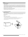
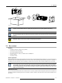
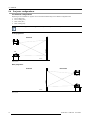
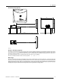
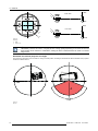
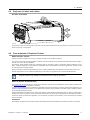

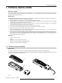
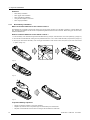
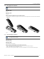
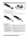
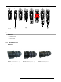
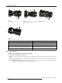
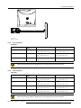
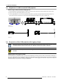
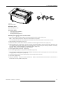

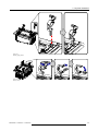
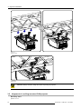
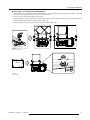

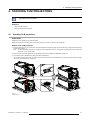
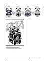
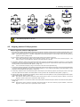
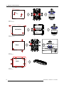
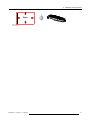


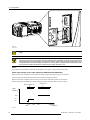
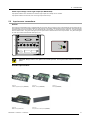
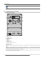
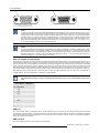


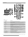
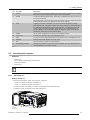
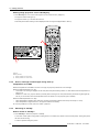
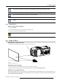
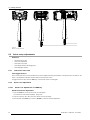
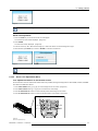
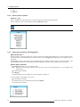
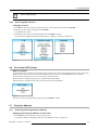
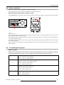

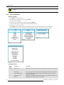
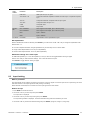
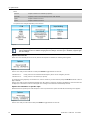
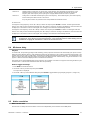
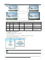
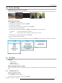
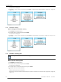
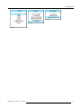

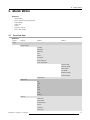
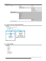
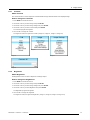
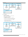
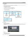
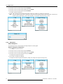
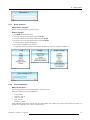
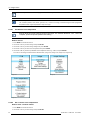
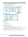
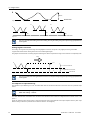
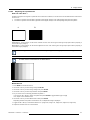
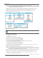
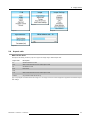
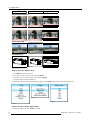
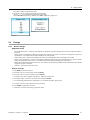
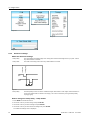
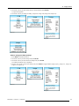
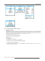
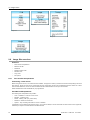
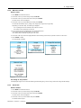
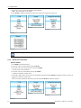
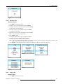
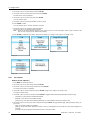
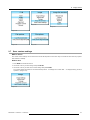

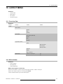
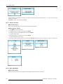
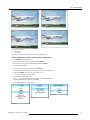

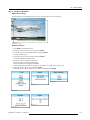
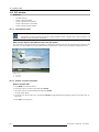
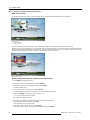
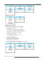
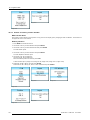
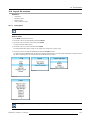
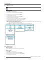
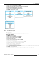
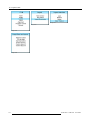
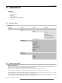
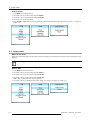
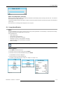
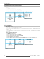
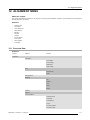
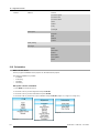
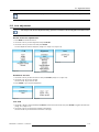
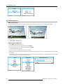
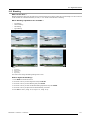
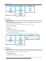
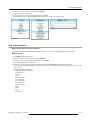
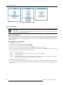
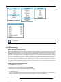
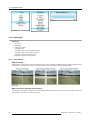
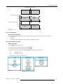

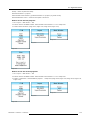
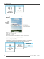

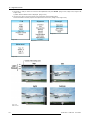
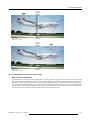
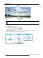
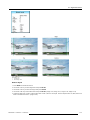
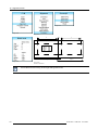
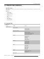
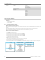
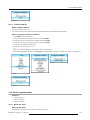
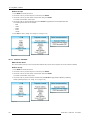
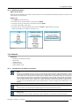
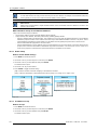

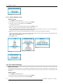
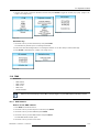
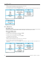
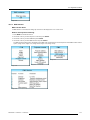

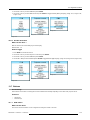
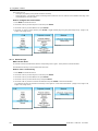
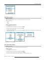

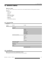
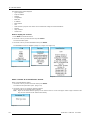

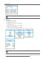
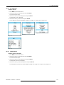
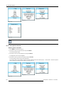
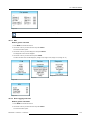
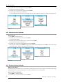
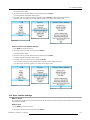
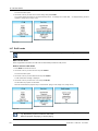
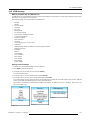
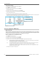
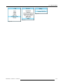

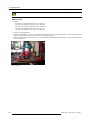
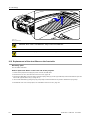
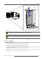
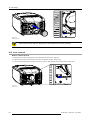
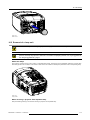
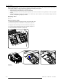
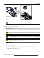
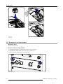
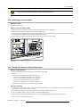
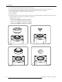
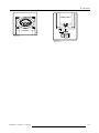

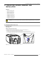
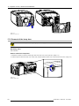
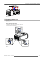
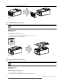
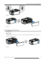
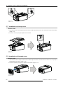
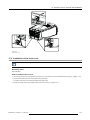
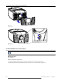


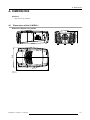
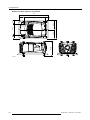
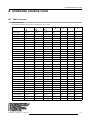
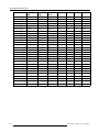

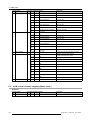
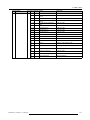

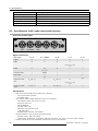
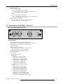
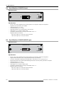
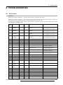
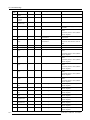
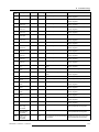

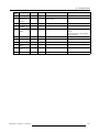

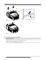
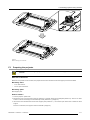
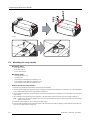
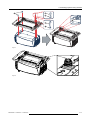


![FLM HD18 [v08]](http://vs1.manualzilla.com/store/data/005664321_1-9e0d84f2b9cac33a4ebfb5904f0dafa1-150x150.png)