1
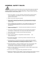
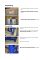
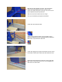
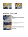
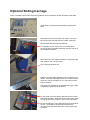
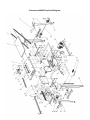
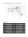
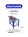
TABLE SAW
OPERATORS MANUAL
MODEL: W625
Charnwood, Cedar Court, Walker Road,
Hilltop Industrial Estate, Bardon Hill, Leicestershire, LE67 1TU
Tel. 01530 516 926 Fax. 01530 516 929
email: [email protected] website: www.charnwood.net
GENERAL SAFETY RULES
WARNING: Do not attempt to operate the machine until you have read thoroughly and understood
completely all instructions, rules, etc. contained in this manual. Failure to comply may result in
accidents involving fire, electric shock, or serious personal injury. Keep this owner's manual and
review frequently for continuous safe operation.
1. Know your machine. For your own safety, read the owner's manual carefully.
Learn its application and limitations, as well as specific potential hazards
pertinent to this machine.
2. Make sure all tools are properly earthed.
3. Keep guards in place and in working order. If a guard must be removed for
maintenance or cleaning, make sure it is properly replaced before using the
machine again.
4. Remove adjusting keys and spanners. Form a habit of checking to see that
the keys and adjusting spanners are removed from the machine before
switched it on.
5. Keep your work area clean. Cluttered areas and workbenches increase the
chance of an accident.'
6. Do not use in dangerous environments. Do not use power tools in damp or
wet locations, or expose them to rain. Keep work areas well illuminated.
7. Keep children away. All visitors should be kept a safe distance
8. from the work area.
9. Make workshop childproof. Use padlocks, master switches
remove starter keys.
and
10. Do not force the machine. It will do the job better and be safer at the rate
for which it is designed.
11. Use the right tools. Do not force the machine or attachments to do a job for
which they are not designed. Contact the manufacturer or distributor if there is
any question about the machine's suitability for a particular task.
12. Wear proper apparel. Avoid loose clothing, gloves, ties, rings, bracelets, and
jewellery which could get caught in moving parts. Non-slip footwear is
recommended. Wear protective hair covering to contain long hair.
13. Always use safety glasses. Normal spectacles only have impact resistant lenses.
They are not safety glasses.
14. Do not over-reach. Keep proper footing and balance at all times.
15. Maintain the machine in good condition. Keep the machine clean for best and safest
performance. Follow instructions for lubrication and changing accessories.
16. Disconnect the machine from power source before servicing and when
changing the blade.
17. Never leave the machine running unattended. Turn the power off. Do not leave the
machine until it comes to a complete stop.
18. Do not use any power tools while under the effects of drugs, alcohol or medication.
19. Always wear a face or dust mask if operation creates a lot of dust and/or chips.
Always operate the tool in a well ventilated area and provide for proper dust removal.
Use a suitable dust extractor.
ADDITIONAL RULES FOR CIRCULAR SAWS
1. Ensure that the saw table is clear of off-cuts, tools or anything else that might foul the
work-piece.
2. If your saw has a dust extractor hose connected to the crown guard, ensure that it is
held clear of the table and will not foul the work-piece as it passes over the table.
3. When cutting large sheets of material or long boards use one or more roller stand(s)
to support the work or have a competent helper to support it as it feeds off the rear of
the table.
4. Never use the saw without the riving knife and check that it is in line with the blade
before using the saw.
5. Always use a brush to clear the table of dust or debris. NEVER use your hands,
especially when the machine is running.
6. ALWAYS USE A PUSH STICK WHEN IT IS NECESSARY TO PUSH ANY PIECE
OF MATERIAL OF SUCH SIZE THAT IT WOULD BRING YOUR HANDS WITHIN 30
CM OF THE BLADE.
7. Do not cut material that is badly warped or which has screws or nails in it
8. Be extra vigilant when cutting stock which has loose knots in it as these may fly out
of the saw.
9. NEVER remove the table insert when the saw is running.
10. To avoid exposure to hazardous dust, do not use this saw without connecting it to a
suitable dust extractor.
11. Always work with a sharp saw blade and feed the work at a rate suited to the
thickness and hardness of the material.
Note: This table saw has been designed and built solely as a woodworking machine.
Do not modify it in any way or use for anything other than its designated purpose. Neither the
manufactures nor the supplies are liable for any damage or injury caused by incorrect
assembly, operation or electrical connection of this machine.
Specification
Table size
550(w) x 1600(d)mm
Table size with optional table extension
950(w) x 1600(d)mm
Table height
800mm
Motor (carbon brush)
1600W, 240v single phase
300mm (12”) 30mm
Blade diameter and bore
Blade rotation speed (no load)
3000 rpm
Maximum depth of cut at 90o
60mm
Maximum depth of cut at 45o
40mm
Maximum cutting width
290mm (12”)
Cutting width with optional table extension
690 mm (27”)
Dust extractor hose connection
100mm
Dimensions (WxDxH)
600mm x 1690mm x 1050mm
Weight
60 kg
Rating
Trade
(Note: Imperial measurements approximate)
Risk of Injury!
Never reach into
the running saw blade.
Wear Eye
Protection
Wear Ear
Protection
Rating Description
Trade: Suitable for daily use by professional woodworkers.
Continuously rated, high power and a heavy duty construction. Typically used by several different
operators in a small or medium sized business. Will be used up to the machines maximum limit with
some long work periods. Expected maximum use of 1000 hours annually.
Unpacking
This saw is best unpacked on the floor as it is quite
heavy.
Open the carton, carefully unpack all of the contents
and lift the body of the saw onto a bench, leaving it
inverted.
Familiarise yourself with the parts and take the time to
sort out the various types of nuts and bolts.
Assembly
Leave all bolts finger tight until assembly of the legs is
completed.
Locate the leg with the square hole cut out for the NVR
switch and place it on the table as shown, inside the
turned down edges of the table.
Secure the leg with 4 bolts. M6 x 16mm long bolts with
washes and nuts.
Repeat for the other 3 legs
Next, bolt on the four braces which fit half way down each
leg. There are 2 long rails and 2 short rails.
Bolt the four rails together as shown, using three M6 x
16mm bolts with washers and nuts in each corner.
It does not matter which pair, the long or the short are on
top but please keep this symmetrical.
Place the four black rubber feet on the legs.
True up the assembly and tighten all the bolts.
Locate the rear extension table.
Attach the two support braces, using four M6 x 16mm
bolts with washers and nuts. Noting that they fit inside the
table and on top of the floor stand rail.
Locate the ripping fence guide rail and bolt it onto the front
of the table. Use an M6 x 16mm bolt with washer and nut.
At the other end of the fence guide rail, use a longer bolt
M6 x 20mm. Note how there is a cut out in the guide rail
which fits over a bolt head.
Offer up the NVR switch and fix it in place with the two
self tapping screws provided.
Bolt on the dust extractor port noting that the side entry
faces away from the motor.
Use four M3 x10mm long bolts.
Fit the wheels using four M6 x 16mm bolts with washers
and nuts.
Adjust them, so that the wheels are just clear of the
ground when all four feet are supporting the saw.
The wheels will make contact with the floor and take the
weight of the saw when it is lifted by means of the
handles, which will be fitted later.
Raise the blade by turning the handle at the front of the
saw (See Using the Table Saw on page 13)
Locate the crown guard, loosen the bolt near the dust port
and fit the guard to the riving knife. The bolt will slide into
the slot at the top of the knife. When it is fully seated,
retighten the bolt.
Loosen the two bolts at the right, rear of the table and slot
in the dust hose support. Retighten the bolts.
Fit one end of the dust collection hose to the spigot on the
back of the crown guard, fit the other end to the side inlet
of the dust extractor port and clip the middle into the
support bracket you have just fitted.
Bolt on the two lifting handles, using two M6 x 16mm
bolts, washers and nuts for each one.
Fit the hook to the front right leg, which is used to hang
the push stick.
Locate the fence carrier assembly and the L shaped
fence. Assemble the fence by sliding two square head
bolts into the T-slot in the extrusion, passing them through
the vertical face of the mitre fence base, securing them
with a washer and yellow knob.
The black handle is used to lock the fence along the guide
rail. When the handle is lifted the fence assembly will slide
smoothly along the rail, when the handle is fully
depressed the fence is locked in position.
This is how the completed fence should look. With it
mounted on the front rail and the adjustable mitre gauge
set to 0° it can be used as a rip fence.
When mounted on the left hand side rail, the mitre angle
can be set for crosscutting, up to 60 degrees each way.
Rip fence
Mitre fence
Optional Side Extension Table
If you have purchased the optional right hand extension
table;
Bolt the two support braces to the right hand side floor
stand rail. This gives support to the table while you are
attaching it.
Push a bolt through each of the two holes adjacent to the
legs. Place a washer and nut on the back end. Leave
them loose and with a good length of the bolt protruding
on the outside of the table.
Slot the table over the two protruding bolts and support
the outer edge by guiding the braces so that they sit
inside the turned down edge of the extension table, as
shown. Level the extension table to the main table and
tighten all the bolts.
Optional Sliding Carriage
Note: If installed, remove the mitre fence guiderail which is bolted to the left hand side of the table.
Unpack the components and familiarise yourself with
them.
Identify the front and rear guide rail carriers. Fit one to
each end of the left hand side of the table, as shown.
Note that the front and rear are different.
To install the carrier, remove two of the bolts which
secure the leg to the table. Refit them with the carrier on
the outside of the table.
Next, bolt on the two support brackets, using three bolts,
with washers and nuts, as shown.
Use the larger M8 bolt here.
Slide the carriage table assembly onto the guide rail, as
shown. There are 6 bearings which sit in contact with the
guide rail. They are a tight fit so you may need to push
to get it started.
The lower pair of bearings can be adjusted to get a tight
fit against the guide rail as necessary.
Fix the guide rail to the carriers with the four hex socket
head bolts provided. Note that the front end of the guide
rail, will project about 110mm in front of the main table.
Fit the remaining two cap head bolts through the ends of
the rail. These will act as travel limit stops for the
carriage and prevent the table from coming off the end
of the rail.
Setting The Sliding Table
Firstly set the height:
These holes are slotted so that the carrier may be
adjusted up or down to bring the sliding carriage to the
correct height. Ideally it will be just proud of the table
(0.5mm to 1mm) to allow the work piece to easily slide
over the main table.
Next set the level:
Use this bolt to level the carriage. Turning the bolt
clockwise, will lift the left hand side of the table. Once a
good level has been achieved tighten the nut up against
the face of the guide rail carrier to lock it.
Use a straight edge (or the fence carrier that you have
removed) to check the level of the sliding table. Here
you see a carriage that needs adjusting. Keep adjusting
the bolts until the sliding table and the main table are
correctly aligned.
Take the pivot bolt, M10 x 65mm, place an M10 steel
washer over the bolt and then pass the bolt through the
fence support. Next place a black plastic washer onto
the bolt and then screw the bolt into the threaded hole in
the sliding table. The plastic washer sits between the
fence support and the sliding table.
Tighten the bolt securely but check the fence can still
pivot freely around this point.
Take the locking handle, place a steel washer over the
bolt and then pass the bolt through the fence support.
Next place a black plastic washer onto the bolt and then
pass the bolt through the hole in the sliding table.
Secure the bolt with a steel washer and nyloc nut. The
plastic washer sits between the fence support and the
sliding table.
Use a spanner to adjust the nyloc nut so that when the
locking handle is pressed down the fence will not pivot.
When the handle is lifted the fence should swing around
pivot point.
Slide the heads of the two bolts, M6 x 45mm, into the Tslot of the mitre fence extrusion, pass them through the
fence support and secure them with washers and the
two black plastic wing nuts.
There is an adjustable, flip-over length stop on the
fence, to speed up repetitive work.
Use a set square to set the mitre fence extrusion at 90
degrees to the blade.
The mitre scale has two fixing screws which can be
loosened to make an adjustment to the scale if
necessary.
Next set the 90 degree return stop. The round silver
stop, has a fixing bolt drilled off centre. With the fence
still locked at the 90 degree position, loosen the fixing
bolt and rotate the stop until it touches the back of the
fence support. Tighten the fixing bolt.
Using The Table Saw
Start / Stop Switch
Blade Angle Scale
Blade Angle Locking Knob
Blade Height Scale
Blade Height Adjustment Handle
On/Off Switch
To turn the saw on, press the green button. Wait for the blade to reach its maximum speed
of rotation before commencing with the cut.
To turn the machine off again, press the red button.
The machine is fitted with an NVR (No Voltage Release) switch. This type of switch is
designed so that if the machine is disconnected from the mains whilst running and then
reconnected, the motor will not automatically restart.
Cutting Depth
Adjustments to the cutting depth should be made only when the saw is not running.
Turn the crank handle to set the blade to the required depth. Turn anticlockwise to lower the
blade, turn clockwise to raise the blade. The blade height should always be set so that only
the carbide tips of the blade (approx. 5mm) projects above the wood.
Angle of Cut
Adjustments to the angle of cut should be made only when the saw is not running.
To tilt the blade for making bevel cuts, there are 2 locking knobs. Loosen both of the yellow knobs,
located at the front and the rear of the machine. Push the bottom blade housing around to the required
angle, a scale is provided for guidance. Lock the angle by tightening both of the yellow knobs.
Cutting Width
The rip fence is used to make longitudinal (with the grain) cuts. Set the fence to the required
dimension by measuring with a rule between the fence and the blade. Clamp the fence in
place by firmly pressing down the locking lever.
To avoid kickback, the far end of the fence extrusion should be set correctly.
The fence extrusion should be set so that the end is level with the centre of the saw blade.
This allows the timber space to expand into, after the cut has been made.
When cutting wider pieces the fence extrusion can be moved further towards the back of the
blade, in a line projecting at roughly at 45 degrees out from the centre of the blade.
Mitre Fence
To cut across the grain, use the sliding mitre fence. To set 90 degrees or any other angle,
undo the locking handle and rotate the quadrant to the desired angle. Lock the angle setting
with the plastic handle. The fence extrusion can then be adjusted so thet the end is close to
the blade, giving better support to the work piece. When setting the fence, take care to
ensure the fence will not contact the blade.
Making a cut
Ensure there is enough space around the table for the work piece before starting the cut.
Position your feet in a stable and balanced stance.
When feeding the timber, place your hands on the section of timber being kept. Never hold
the waste part of the timber.
Never force timber through the saw, always let it cut at its own speed.
When cutting narrow pieces - use the push stick.
Blade Removal and Replacement
Always switch off and unplug the saw before removing or replacing the blade.
The table insert panel surrounding the blade is
removable to allow access to the interior of the saw.
Remove the crown guard and then remove the four
screws using a cross head screw driver and lift out the
panel.
The saw is supplied with 2 spanners. Use the peg
spanner to lock into the saw blade flange and hold the
blade stationary. Use the 13mm spanner to undo the
locking bolt.
Please Note: The bolt is Left Hand Thread
Turn it clockwise to undo it.
Refit the blade, flange and bolt in the same way.
Troubleshooting
Saw vibrates
Check all nuts and bolts for tightness and
check that blade is not damaged.
Cuts are slow, wood is blackened
Examine the blade. If any Tungsten tips are
missing or broken the blade should be
replaced. If the tips are blunt, the saw blade
may be professionally sharpened.
Saw stalls
Feed rate too high, slow down.
Rip fence is not parallel to blade
Bring the fence up to the blade and re-align
the fence so it is parallel, using the large
locking know on the mitre fence base.
Lower saw guard fills with dust
It is essential to use a vacuum extractor or
chip collector with this machine. If one is
being used, check for blockages in the hose.
When pressing start, nothing happens
Check power supply, fuse in plug and switch.
Declaration of Conformity for CE Marking
Charnwood Declare that Woodworking Circular Saw, Model W625
Conforms with the following Directives:
Machinery Directive 2006/42/EC
Low Voltage Directive 2006/95/EC
EMC Directive 2004/108/EC
And further conforms to the machinery example for which the EC type examination
Certificate No. BM 50163884, AN 50232926 and AE 50221146 have been issued by TUV
Rheinland LGA Products GmbH, Tillystrasse 2, 90431, Nurnberg.
I hereby declare that equipment named above has been tested and found to comply with the
relevant sections of the above referenced specifications. The machinery complies with all
essential requirements of the directive.
Signed:
Richard Cook, Director
Dated: 11/11/2009
Location: Leicestershire
Charnwood W625 Exploded Diagram
W625 Parts List
Item
01
02
03
04
05
06
07
08
09
10
11
12
13
14
15
16
17
18
19
20
21
22
23
24
25
26
27
28
29
30
31
32
33
34
35
36
37
38
39
40
41
42
43
44
45
46
47
48
49
50
51
52
53
54
Part
Table
Leg
Rail - long
Rail - short
Rear extension table
Brace for extension table
Saw blade
Locating plate
Spacer
Riving knife support
Pressure plate
Riving knife
Crown guard - right
Crown guard - left
Rise and fall handle
Guide block
Connection block
Motor bracket
Blade housing box
Blade assy. support - front
Blade assy. support - rear
Blade arbour
Blade flange - inner
Blade flange - outer
Blade housing plate
Protective cap
Pointer
Mitre fence base
Fence Extrusion
Fence guide rail
Roundhead Screw M3 x 40mm
Circlip 6mm Diameter
Spring
Washer M6
Locking plate
Mitre fence locking knob
Pin
Table insert
Dust extraction port
Scale
Angle indicator
n/a
Wheel
Wheel bracket - left
Wheel bracket - right
Axle
Push Stick
Handle lift limiter
Handle attachment bracket
Lifting Handle
Dust hose support
Blade Changing Spanner
Depth of cut scale
Push Stick hanger
QTY
1
4
2
2
1
2
1
1
2
1
1
1
1
1
1.
1
1
1
1
1
1
1
1
1
1
1
1
1
1
2
2
1
1
58
1
1
1
1
1
1
1
2
1
1
1
1
2
2
2
1
1
Item
55
56
57
58
59
60
61
62
63
64
65
66
67
68
69
70
71
72
73
74
75
76
77
78
79
80
81
82
83
84
85
86
87
88
89
90
91
92
93
94
95
96
97
98
99
100
101
102
103
104
105
106
107
108
Part
Motor, Induction 240v, 1600w
NVR switch
Depth of cut adjustment handle
Tilt locking knob
Hinge
Pivot bolt (M6 x 8mm special)
Plastic Nut
Pointer
Dust extractor hose (not shown)
Cam
Cap head bolt M6 x 20mm
Nut M6
Washer M6
Spring washer M6
Hex. head bolt M6 x 16mm
Self tapping screw 14mm
Coach bolt
Coach bolt
Pan head screw M6 x 25mm
Coach bolt M6 x 20mm
Hex. Nut
Hex. head bolt M8 x 45mm
Hex. head bolt
Hex. head bolt
Hex. head bolt
Hex. head bolt M6 x 16mm
Hex. head bolt
Hex. head bolt
Hex. head bolt
Hex. Nut
Locking handle
Hex. Nut
Hex. Nut M10
Hex. Nut
Self locking nut
Self locking nut M6
Coach bolt
Screw
Round head bolt M3 x 10mm
Screw
Hex Head Bolt M3 x 10mm
Mitre gauge support plate
Bolt M3 x 16mm
Self tapping screw M2 x 24mm
Lock washer M3
Lock washer
Self locking nut M8
Circlip 12mm Diameter
Large washer M6 x 18mm
Large washer
Self locking nut M10
Rubber foot
Circlip
Hex. nut
QTY
1
1
1
1
2
1
2
1
1
1
6
6
58
10
45
4
2
1
1
2
1
2
2
1
1
45
4
4
4
1
1
1
1
2
3
4
2
2
11
5
11
1
4
5
7
1
12
1
9
4
1
4
1
2
Charnwood W625SC Exploded Diagram - Sliding Carriage Assembly
W625SC Parts List
Item
01
02
03
04
05
06
07
08
09
10
11
12
13
14
15
16
17
18
Part
Cap head bolt M6 x 16mm
Guide rail carrier – rear
End cap
Wing nut M6
Hex head bolt M6 x 16mm
Support bracket – rear
Hex. head bolt M6 x 16mm
Washer M6
Spring washer M6
Nut M6
End cap
Washer M6
Spring washer M6
Nut M6
Bolt (M6 x 45mm special)
Flip-over stop
Locking handle
Stop bracket
QTY
2
1
2
8
2
1
4
4
2
2
1
16
4
8
2
1
1
1
Item
19
20
21
22
23
24
25
26
27
28
29
30
31
32
33
34
35
Part
Cap head bolt
Self tapping screw
End cap
Mitre fence extrusion
Pivot bolt M10 x 65mm
Plastic Washer M10
End cap
Fence Support
Washer M10
Sliding Table
Wing nut M6
Cap head bolt M6 x 16mm
Support bracket – front
Guide rail carrier – front
Bearing bracket
Guide rail
Hex. head bolt M6 x 16mm
QTY
1
2
1
1
1
1
2
1
2
1
2
4
1
1
1
1
8