1
CESSNA
CESSNA
MORE PEOPLE SUY AND
FLY CESSNA AIRPLANES
THAN ANY OTHER MAKE
"TAKE YOUR CESSNA HOME
FOR SERVICE
MODEL
AT THE SIGN
OF THE CESSNA SHIELD"
I
1960
CESSNA AIRCRAFT COMPANY
WICHITA. KANSAS
THE WORLD'S LARGEST
PRODUCER OF GENERAL
AVIATION
AIRCRAFT
SINCE 1956
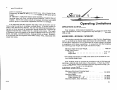
OWNER'S
MANUAL
Congratulations . . . . . .
Welcome to the ranks of Cessna owners! Your Cessna has been designed and constructed to give you the most in performance, economy,
and comfort. You will find flying it, either for business or pleasure, a
pleasant and profitable experience.
This Owner's Manual has been prepared as a guide to help you get
the most pleasure and utility from your airplane. It contains information about your Cessna's equipment, operating procedures, and performance; and suggestions for its servicing and care. We urge you to
read it from cover to cover, and to refer to it frequently.
Our interest in your flying pleasure has not ceased with your purchase
of a Cessna. World-wide, the Cessna Dealer Organization backed by
the Cessna Service Department stands ready to serve you. The following services are offered only by your Cessna Dealer:
t.O
t.O
¢
G
G
..-'
¢
~z
If)-
~0..
(./)
z
N
u
0
_J
I
5I
J
a:
:::l
:z:
a:
:&
.V)
a:
UJ
:z:
3
0
(")
5I
10
J
U)
en
....
0
........
....N
N-
If)
0
0.
P199·13-RAN0-200-8n6
5I
........
sM
5I
sa:
N:Z:
('IIV)
¢V)
coUJ
cou
1) FACTORY TRAINED MECHANICS to provide you
with courteous expert service.
2) FACTORY APPROVED SERVICE EQUIPMENT to
provide you with the most efficient and accurate workmanship possible.
3) A STOCK OF GENUINE CESSNA SERVICE PARTS on
hand when you need them.
4) THE LATEST AUTHORITATIVE INFORMATION
FOR SERVICING CESSNA AIRPLANES, since Cessna
Dealers have all of the Service Manuals and Parts Catalogs,
kept current by Service Letters and Service News Letters
published by Cessna Aircraft Company .
We urge all Cessna owners to use the Cessna Dealer Organization to
the fullest.
A current Cessna Dealer Directory accompanies your new airplane.
The Directory is revised frequently, and a current copy can be obtained from your Cessna Dealer. Make your Directory one of your
cross-country flight planning aids; a warm welcome awaits you at
every Cessna Dealer.
1------------ 211'-7"-------i
Table of Contents
* If J:Otatlng beacon is installed on vertical fin,
add 3" to maximum height o( alrpla.D.e.
:==:=::==:=:=:=:=:=::=:==:=::=:=:==:=:=::=:=:=:==::page=:
SECTION I
DESCRIPTION
. 1-1
SECTION II
NORMAL PROCEDURES
. 2-1
SECTIONffi
OPERATING DETAILS .
3-1
SECTION IV
EMERGENCY PROCEDURES
4-1
SECTIONV
OPERATING LIMITATIONS
5-1
SECTION VI
CARE OF THE AIRPLANE
6-1
DEALER FOLLOW -UP SYSTEM
SECTION VII -
OPERATIONAL DATA
ALPHABETICAL INDEX . • . . • . • .
6-8
7-1
Index-1
1------------ 35'-9"------------1
ii
iii
~
bll
--
a;~~.~t
u~
oo~
0
bbg
~
>
.......... ~&.JW.!.t£.....L.... ...... •
fl. 01
~ ~
sg
0
&14
.s
]~
Description
0.,~
.z,.,.aau~b'il~
ocuu.o~8s
u
e.g.g~ "'U~<
SB'E-tr-. e~-uGI ~
~"ee-oaii~"
P..$-·~t,~
... ~ ll
!jill!:_
~"~"s<3,.~P..~
ilalt.t. ~
E:_gt~.~ft;§tll·-u>
o .....
:g~~,~>-
.... JM:-
;;8,.:::.!P,'il i:lj!.!l
ONE OF THE FIRST STEPS in obtaining the utmost performance, service, and flying enjoyment from your Cessna is to familiarize yourself
with your airplane's equipment, systems, and controls. This section describes location, operation, and function of the various items of equipment,
intentionally omitting reference to some items which are obvious.
<~~<liilo..:IP..oo<
ENGINES.
Two horizontally - opposed, sixcylinder, Continental 10-470-D engines, rated at 260 horsepower at
2625 RPM, power your 310D. The
engines have wet-sump oil systems,
dual magnetos, continuous-flow fuel
injection, and jet-augmenter exhaust
systems including mufflers.
ENGINE CONTROL PEDESTAL
§~
..
.5
.
~~
>~
-
..,liii.S
p..
~
.,...
ll' a<3 go
o "a~
CJ S:aC>
..,;~8-c
~ a-~~
ee!i-§
::loEQ)~
""bu eli-;""'
~
!!!.
11.1
~
..,::l •...
a ...
.c~
".:l
~,S~o~~~~ic
11lt~!l!lllll!i1ilti!!:~i1!~:-tt!t!!llitit~:!:!tlli~l !lli! I£ ii!
iv
The throttle, mixture levers, and
propeller pitch levers are grouped
on top of the engine control pedestal. They are readily accessible
from either the pilot's or copilot's
seats. Control lever selections are
clearly marked between each group
of controls. Numbered index marks
are also provided between the mixture levers to facilitate mixture settings. A knurled friction knob on
the right side of the pedestal can be
rotated to adjust friction on the control levers to prevent creeping.
The pedestal also houses the induction air control handles and trim
tab control wheels, and has provisions for mounting an automatic
pilot control head.
Refer to Sections II, III, and IV
for further discussion concerning
the use of engine and propeller controls under normal and emergency
conditions.
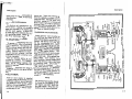
INDUCTION AIR CONTROL HANDLES.
The induction air control handles
operate doors in the engine air intakes to select either filtered cold
air or air heated by exhaust manifold heaters. Cooling and induction
air flow is shown in the Air Induction System Diagram on page 1-3.
If ice should form in the induction
system, as evidenced by an unexplained drop in manifold pressur'e,
pull the induction air control handle,
for the engine involved, full out and
lock it in position by rotating it. Do
not use an intermediate position.
The alternate air (heated air) doors
are spring-loaded closed and their
control linkage permits engine suction to open them automatically if
1-1
Description
is blocked, regardless
l'Pomon of the induction air
control handles.
IGNITION SWITCHES.
The four ignition switches control
the dual magnetos on each engine.
The switches may be operated individually; or by using a hinged bar
mounted above them, all four may
be turned off at once. For normal
operation, all four switches should
be ON. Individual switches should
be turned off only for checking purposes. When the engines are stopped, all four switches should be OFF
(down).
STARTER BUTTONS.
The starter switches are pushbuttons with red, cup-shaped guards
to prevent them from being pressed
accidentally.
PROPELLERS.
The airplane is equipped with two
all-metal, hydraulically-operated,
constant-speed, full-feathering, twobladed propellers. Propeller operation is controlled by the propeller
pitch levers through a mechanical
linkage to the engine-driven propeller governor on each engine.
OIL SYSTEM.
The oil capacity of each engine is
twelve quarts. The last six quarts
of oil are considered unusable because, in an eld:reme nose high climb
with a low oil level, it is possible
1-2
to uncover the oil pick-up line, resulting in low oil pressure. Add oil
if the level is below nine quarts, and
fill the sump if an extended flight is
planned.
The oil quantity is easily checked
by opening the left rear access door
on each engine nacelle, and reading
the oil level on the dipstick located
just aft of the rear left cylinder of
each engine. The dipstick incorporates a spring lock which prevents
it from working loose in flight. The
dipstick is removed by rotating it
until the lock is disengaged, and
pulling it out. When replacing the
dipstick, make sure that the spring
lock is engaged.
Th-e oil filler caps are under the
small access door on top of each
nacelle, and can be removed by rotating them counterclockwise. In
replacing the oil filler caps, see
that they are on firmly and turned
clockwise as far as they will go.
The oil sump drain plug is accessible through a hole in the bottom
of the cowl.
The engine oil coolers are thermostatically -controlled, to maintain
oil temperatures near optimum. To·
prevent oil congealing in the coolers
when operating in low temperatures,
warm oil circulates continuously
through warm-up passages in their
centers. For most winter weather,
no special shutters or baffles are
necessary with these coolers.
3=:::~
ENGINE AIR INDUCTION SYSTEM
Ram
Filtered
Air
ENGINE
CYLINDER
INDUCTION
AIR FILTER
INDUCTION
AIR HANDLE
=C>
=C>
=C>
RAM AIR
MANIFOLD
HEATER
FUEL.AIR
CONTROL UNIT
·:::;:::::: :::::::::::::::::;:::::::::~:::::::::::::::::::::::;:::=::::::::~::::::::~:::::::::::::~~~==::=:::::::::::~::::::::: =::::::::::
Heated
ENGINE
CYLINDER
:::::::;:::::::::::;:~:::::::::::::::::·:::::::::::::::~=::;x::::::::::::::::::::::::::. ::::: ::::::::::::~::::::::::::: :::::::::::;~:=::::::: =:=:::::::::::::::::
INDUCTION
AIR FILTER
ALTERNATE
AIR DOOR
Air
BACKFIRE
DOORS
,____
INDUCTION
AIR HANDLE
J )1~\;
Jl.
·--· ~
=C>
RAM AIR r:::::l>
c::::t>
FUEL-AIR
CONTROL UNIT
r:::::::::C>
OIL SPECIFICATION AND GRADE.
CODE
Refer to the Servicing Diagram on
pages 6-6 and 6-7 and the Service
Requirements Table on the inside
.
ALTERNATE
AIR DOOR
{
IIIIll!D!lJ>
_.
C 0 LD A I R
FILTERED COLD AIR
HEATED AIR
MANIFOLD
HEATER
f~~!i
1-3
Description
Description
back cover for the recommended oil
specification, grades, and servicing
intervals.
OIL SYSTEM INSTRUMENTS.
An electric oil temperature gage
and a direct- reading oil pressure
gage are included in the engine gage
unit for each engine. A green arc
on each gage dial indicates the normal operating range. Refer to Section V for instrument markings.
OIL DILUTION SYSTEM.
To prevent oil congealing when the
engines are shut down in extremely
low temperatures, the optional oil
dilution system injects fuel into the
engine oil system, reducing oil viscosity. When the engines are started and warmed up again, the fuel
evaporates and the oil returns to its
normal viscosity.
The oil dilution system is controlled by a single, three-position
switch placarded L (left engine),
OFF, and R {right engine). The
switch is spring-loaded to the OFF
position.
Detailed instructions for using the
oil dilution system are given in Section III.
FUEL SYSTEM.
Fu·el for each engine is supplied
by a main tank oiX' each wing tip and
an optional auxiliary tank in the wing
just outboard of each nacelle. Each
engine has its own complete fuel system; the two systems are interconnected only by a crossfeed for emer1-4
gency use. Vapor and excees fuel
from the engines are returned to the
main fuel tanks. Submerged electric
auxiliary pumps in the main fuel
tanks supply fuel for priming and
starting, and for engine operation
if an engine-driven pump fails. The
optional auxiliary tanks have no return lines or electric pumps.
V)
~
z
<
.....
FUEL SELECTOR VALVE HANDLES.
Rotary selector valve handles on
the cabin floor just back of the engine control pedestal control the fuel
system. The selector valve placards
for the standard fuel system are
marked LEFT ENGINE OFF, LEFT
MAIN and RIGHT MAIN for the left
engine selector, and RIGHT ENGINE
OFF, RiGHT MAIN and LEFT MAIN
for the right engine selector. The
crossfeed position of each selector
valve is the one marked for the opposite main tank. With optional auxiliary tanks, each selector has a
fourth position, marked AUXILIARY
which will feed its engine only from
its auxiliary tank. The auxiliary
tanks cannot be crossfed.
The fuel selector valve handles
form the pointers for the selectors.
The ends of the handles are arrowshaped and point to the position on
the selector placard which corresponds to the valve position.
NOTE
The selector valve handles should
be turned to LEFT MAIN for the
left engine and RIGHT MAIN for
the right engine, during take-off,
landing and all normal operation.
...J
w
::::>
u..
>D'
<
::::i
><
::::>
<
•~ e
~~
... \ .
D
~
e:
~ t i! ~'
~~ "
~~~~=
~!~>~
~Ri'i u~m
:I:
e:; ~~!
BOt~~m
.....
~
•
=~
I
i!W
t~
:E
w
~~
~§
.....
V)
>V)
...J
w
::::>
u..
.
~
d
~~
=
t~~·
~s
~~
1-5
D~acription
AUXILIARY FUEL PUMP SWITCHES.
Th~ auxiliary fuel pump switches
are three-position switches, marked
·ON, OFF and PRIME. The PRIME
positionruns the pumps at low speed,
providing approximately 5 psi pressure for priming and starting. The
ON position also runs the pumps at
low speed, as long as the enginedriven pumps are functioning. With
the switch in the ON position, however, if an engine-driven pump fails,
. the auxiliary pump on that side will
"be switched to high speed automatic. ally, providing sufficient fuel for
. all engine operations including take. off power. As a safety measure,
always take-off and land with the
auxiliary pump switches in the ON
position.
FUEL QUANTITY INDICATORS.
Fuel quantity in each main tank is
shown by a dual-reading fuel quantity
indicator on the right side of the
instrument panel. A second dual
gage shows the fuel in each optional
auxiliary tank. The indicators are
electrically-operated, and with the
battery switch on, indicate in gallons
the amount of fuel remaining.
FUEL PRESSURE GAGE.
The fuel pressure gage is a dual
instrument calibrated in pounds per
square inch. The fuel pressure gage
used with the Continental injection
system indicates metered fuel pressure; i.e., the pressure at which
fuel is delivered to the spray nozzles
and fuel pressure at this point cor-
1-6
Description
relates directly with fuel flow. Thus,
the gage is primarily a flowmeter.
The gage dial is marked with segments of arc corresponding to the
proper fuel pressures for various
power settings, so that it may be
used to set the mixture quickly and
accurately. It has cruise power settings on its low-pressure portion and
take-off pressure settings for various
altitudes on its high-pressure portion. The take-off markings indicate maximum-performance take-off
mixtures for the altitudes shown,
making it practical to lean the mixture on a high-altitude take-off .
In the cruise power range, the lowpressure edge of each green segment
is the normal-lean setting and the
high-pressure edge is the best-power
setting, for that percentage of power.
In the take-off and climb range, each
segment represents a maximumpower mixture for an altitude range:
the low-pressure edge is the setting
for the marked altitude and the highpressure edge is the setting for a
thousand feet lower. The sea-level
s~ment represents a full-rich takeoff power range.
NOTE
The fuel pressure settings on the
take-off and climb power segment
of the dial are for 2625 RPM and
full throttle, only. Climb power
settings at lower RPM should be
taken from the power computer.
FUEL STRAINERS AND DRAINS.
Water and solid materials which
may collect in the fuel tanks are
trapped by strainers and sumps in
each tank and a strainer and sediment bowl in each engine nacelle.
The nacelle fuel strainers may be
drained by opening each left rear
nacelle door and pulling a T -handle
mounted on the side of the nacelle,
which operates a valve in the strainer bowl. When the handle is released, the spring-loaded valve will
close.
The sump in each main fuel tank is
fitted with a quick drain valve, operated with a special hollow-handled
screwdriver which is kept in the
map compartment. The main tank
drains are accessible through small
holes in the lower access plates. To
drain a main sump, engage the special
screwdriver with the end of the valve,
press upward and rotate the screwdriver counterclockwise. Fluid in
the sump will flow through the hollow
handle of the screwdriver. Close
the valve by rotating the screwdriver
clockwise and releasing the upward
pressure sharply. For draining a
large quantity of fuel, the valve may
be turned full counterclockwise and
the pressure released; a detent at
this point will hold the valve open.
The auxiliary tank drains extend
through the lower wing skin and have
no detents. To drain an auxiliary
sump, press upward on the end of
the valve, using the screwdriver.
To completely drain the tank, unscrew the valve from the fitting.
Plugs for draining the fuel crossfeed lines are accessible by remov-
1-7
Desel'iption
Description
ing the lower right wing root fairing.
Recommended intervals for draining the sumps, strainers and fuel
lines are given in the Servicing Diagram on pages 6-6 and 6-7, and in
Section II.
SWITCH & CONTROL
PANELS
I
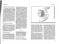
ELECTRICAL POWER SUPPLY
SYSTEM.
=
-==- - =-=
Electrical energy is supplied by a
28-volt, negative-ground, directcurrent system, powered by a 25ampere engine-driven generator on
each engine. A 50-ampere generator
system is available as optional equipment. Two 12-volt batteries, connected in series, are located in the
left wing just outboard of the engine
nacelle. An optional external power
receptacle can be installed in the left
wing under the batteries. The receptacle accepts a standard external
power plug.
BATTERY AND GENERATOR
SWITCHES.
1.
2.
3.
4.
5.
6.
7..
8.
9.
10.
11.
12.
13.
14.
15.
1-8
Battery and Generator Switches
Auxiliary Fuel Pump Switches
Left Starter Button
Ignition Switches
Right Starter Button
Automatic Pilot Power Swltch (Opt. Equip.)
Vacuum Source Selector Valve Knob
OU Dllut!on Swltch (Opt. Equip.)
Post :rYPe Llght (Typical)
Landing Gear Up PO<iition Light
Landing Gear Switch
Optional Switch Space
Wing Flaps Swttch
Left Wing Light Switch (Opt. Equip.)
Cabin Alr Temperature Control Knob
16.
17.
18,
19.
20.
21.
22.
23.
24.
25.
26.
27.
28.
29.
30.
Cabin Air Knob
Defrost Knob
Propeller Anti-Ice Power Switch (Opt, Equip.)
Propeller Anti-Ice Rheostat (Opt. Equip.)
Landing Gear Down Position Light
Lsnding Llghte Switches (Right Switch Opt.)
Taxi Light Switch (Opt. Equip.)
Navlgallon Lights Switch
Rotating Beacon Switch (Opt. Equip.)
Pilot Heat Switch
Cabin Heater Switch
Compass Light Rheostat
Switch Psnel-Fuel Selector Light Rheostat
Engine Instrument Light. Rheostat
Flight Instrument-Radio Lights Rheostat
A battery switch and two generator
switches control the electrical power
supply system. The switches may
be operated individually or all three
may be turned off at the same time,
by using the hinged bar mounted above
them.
The separate battery and generator
switches provide a means of checking
for a malfunctioning generator circuit, and permit such a circuit to be
cut off. If a generator circuit fails
or malfunctions, or when one engine
is not running, the switch for that
generator should be turned off. Operation should be continued on the
functioning generator, using only
necessary electrical equipment. If
both generator circuits should malfunction, equipment can be operated
at short intervals and for a limited
amount of time on the battery alone.
In either case, a landing should be
made as soon as possible to check
and repair the circuitS.
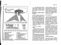
CIRCUIT BREAKERS.
All of the electrical systems l.n the
airplane are protected by "push-toreset" type circuit breakers located
in a circuit breaker panel on the left
cabin wall. The panel is covered by
a metal door which is hinged along
the bottom edge. If your airplane
is equipped with optional 50-ampere
generators, two additional circuit
breakers are mounted on a small
panel below and slightly forward of
the main panel.
If a circuit is inoperative, wait
approximately thre.e minutes for the
thermal unit to cool, then press the
circuit breaker button to reset the
breaker. If resetting the breaker
does not restore power, the circuit
should be checked for loose connections or defective components. If a
circuit breaker pops out a second
time, do not try to reset it again,
but turn off the controlling switch
for that circuit until the fault can be
corrected.
FLIGHT CONTROLS.
Conventional wheel and rudderpedal controls operate the primary
flight control surfaces. Each surface has an adjustable trim tab and
1-9
:Qes~ription
Description
TO OPTIONAl RADIO
o5o
TO OPTIONAL RADIO
TO OPTIONAL RADIO
TO OPTIONAL RADIO
RIGHT GENERATOR
SWITCH
LEFT GENERATOR
SWITCH
Number under drcuit
breaker denol~l ils
amperage capacity.
TO OPTIONAL RADIO
TO OPTIONAL RADIO
TO AUTOMATIC PILOT (OPT)
TO FLARES (OPT)
TO PITOT HEAT
TO STALL WARNING HEAT
TO LEFT ENGINE GAGE
TO LEFT LANDING LIGHT MOTOR
GENERATOR
GENERATOR
TO LEFT AUXILIARY FUEl PUMP
TO OUTSIDE AIR TEMP. INDICATOR
TO RIGHT ENGINE GAGE
TO RIGHT LANDING LIGHT MOTOR (OPT!
TO TAXI LIGHT (OPTI
TO RIGHT AUXILIARY FUEL PUMP
TO
TO
TO
TO
STARTER
SWITCH
DUAL FUEL GAGE
COMPASS LIGHT
REAR DOME LIGHT
WHITE FLOOD LIGHT
TO CABIN IUATER
TO PROPELLER ANTI-ICE (OPT)
TO WING FLAPS DOWN CIRCUIT
LEFT
STARTER
SOLENOID
STARTER
SOLENOID
' ( } - - - - - - TO TRANSMITTER SIDETONE-KEYING RELAY (OPT!
TO LEFT WING LIGHT (OPT)
TO TURN & BANK INDICATOR
TO FLAP POSITION INDICATOR
TO STALL WARNING HORN
TO WING FLAPS UP CIRCUIT
TO FLIGHT INSTRUMENT LIGHTS
TO RADIO DIAL LIGHTS
TO LANDING GEAR MOTOR
TO LANDING GEAR RELAY
EXTERNAL
POWER
(OPT)
TO LANDING GEAR INDICATOR LIGHTS
TO LANDING GEAR WARNING HORN
TO NAVIGATION LIGHTS
TO OIL DILUTION
BATTERIES
(2 - 12 VOLT CONNECTED IN SERIES)
SWITCH
BATTERY
SOLENOID
.------NOTE------,
&~
STANDARD 25- AMPERE SYSTEM IS ILLUSTRATED.
OPTIONAL SO- AMPERE SYSTEM DIFFERS ONLY IN
GENERATOR CONTROl CIRCUIT.
f:JtUete~t t)~ t)~-1-10
TO REO FLOOD LIGHT
TO FRONT DOME LIGHT
TO BAGGAGE COMPARTMENT LIGHT
TO LEFT LANDINO LIGHT
TO FRONT CIGAR LIGHTER
TO ENGINE INSTRUMENT LIGHTS
TO SWITCH PANEL LIGHTS
TO FUEL SELECTOR LIGHT
TO RIGHT LANDING LIGHT (OPT)
TO REAR CIGAR LIGHTER
TO ROTATING BEACON (OPT!
TO OPTIONAL RADIO
1-11
Description
Description
the elevator is fitted with a downspring for improved longitudinal
stability. A bungee interconnects
the ailerons and rudder, for better
lateral stability in certain flight maneuvers.
CONTROLS LOCK.
The controls lock, normally kept
in the map compartment, should be
installed on the pilot's control column
whenever the airplane is parked.
When the lock is installed, a large,
red metal flag covers the ignition
switches and starter buttons, to prevent inadvertently starting the engines with the controls locked. Install the lock as shown below.
CONTROL
LOCI(
J?t:uovr eavRt'
START/Nt: £NGINC
TRIM TAB CONTROLS AND
INDICATORS.
The aileron, elevator, and rudder
trim tabs are operated by tab control wheels. located on the engine control pedestal. A mechanical position indicator· in each system shows
the position of the trim tab. The
aileron tab position indicator is marked ROLL, with L (roll left) and R
(roll right) on their respective sides.
The elevator tab position indicator
is labeled NOSE DOWN, NOSE UP,
and TAKE-OFF. At the take-off'
marking, there is a small arrow
which shows the most satisfactory
elevator trim for normal take-offs.
The rudder tab position indicator is
labeled NOSE, with L (nose left) and
R (nose right) on their respective
sides.
WING FLAPS SWITCH.
The wing flaps switch controls the
position of the electrically-operated
wing flaps. The UP and DOWN positions of the switch are momentary
hold-on positions; the switch automatically returns to the middle (OFF)
position when released. The flaps
can be lowered or raised to any position between 0° and 45°, and stopped
at any position by allowing the flap
switch to return to the OFF position.
The flaps will remain in the selected
position until the switch is moved
to raise or lower them. At the extreme of travel, limit switches stop
the flaps automatically.
Flap position is shown by an electric indicator located just above the
engine control pedestal. The indicator is marked in degrees of flap
deflection from full up.
Under normal conditions at 4830
pounds gross weight, the use of 45°
flaps will lower the power-off stalling speed approximately 10 MPH
(84 MPH to 74 MPH TIAS), to permit a slow, steep approach for short
field landings over an obstacle. The
flaps can be extended to 15 o at any
airspeed below 160 MPH, and to 45°
at any· speed below 140 MPH. They
should never be extended above these
speeds, due to structural limitations.
For take-off, never use over 15° flap.
LANDING GEAR SYSTEM.
The landing gear is of the fully1-12
retractable, tricycle type, incorporating a steerable nosewheel. The
gear retraction system is operated
by an electric motor which actuates
a gear box mechanism and linkage.
To help prevent accidental retraction, an automatic safety switch on
the left shock strut prevents retraction as long as the weight of the airplane is sufficient to compress the
strut.
Landing gear doors fully enclose
the landing gear when retracted, and
are opened by mechanical linkage
when the gear extends. A two-tread
assist step also is mechanically connected to the landing gear linkage,
and swings down out of the fuselage
when the gear extends, to provide
easy access to the right wing walk
and cabin door.
Position lights and a warning horn
provide visual and audible gear position indications to the pilot. A pushto-reset circuit breaker protects the
landing gear motor circuit in the
event of an overload, and a handcrank is used to extend the landing
gear if the electrical system is inoperative.
LANDING GEAR SWITCH.
The landing gear switch can be
identified by its small wheel-shaped
knob. The knob must be pulled out
before the switch can be moved from
one position to another. When released, the knob automatically locks
in the slot of the selected position.
The switch is marked GEAR, and
the positions are labeled UP (to raise
the landing gear) and DOWN to lower the landing gear). A center (OFF)
1-13
Description
Description
position disconnects the electrical
circuit. The OFF position need be
used only when lowering the gear
with the handcrank.
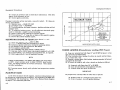
LANDING GEAR HANDCRANK.
The handcrank for manually lowering the landing gear is located just
below the right edge of the pilot's
seat. Normally, the crank is folded
and stowed in a clip beside the seat.
To use the crank, pull it out from
its storage clip and unfold it until
it locks in operating position. To
stow the crank, push the lock release button on the crank handle,
fold the handle and insert it in the
storage clip. The seat must be tilted
back at least one notch, to clear
the crank handle.
NOTE
The handcrank handle must be
stowed in its clip before the gear
will operate electrically. When
the handle is placed in operating
position, it disengages the landing gear motor from the actuator
gear.
The procedure for manually lowering the gear is given in Section IV.
LANDING GEAR POSITION LIGHTS.
Two landing gear position lights
are mounted one above and the other
below the landing gear switch. The
lights are push-to-test type with
dimmiqg shutters. Clockwise rotation of the lens holder on the lights
LANDING GEAR HANDCRANK
CD PILOT'S SEAT
0 RELEASE BUTTON
CD HANDCRANK (EXTENDED)
CD HANDCRANK (FOLDED)
CD STOWAGE CLAMP
1-14
closes the shutters, permitting only
a diffused ring of light to be transmitted through the lens. With the
shutters in the open position (lens
holder rotated counterclockwise),
illumination of the light is unobstructed. The upper light is red,
and is on at all times when the gear
is fully retracted. The lower light
is green, and illuminates only when
the landing gear is fully extended
and locked. The green light is connected in series with a down indicator switch on each wheel strut, and
remains off until all three gears are
down and locked. When neither light
is on, the landing gear is in an intermediate position.
LANDING GEAR WARNING HORN.
The landing gear warning horn is
controlled by the throttles, and will
sound an intermittent note if either
throttle is retarded below 12 inches
of manifold pressure with the gear
up. The warning horn is also connected to the UP position of the landing gear switch, and will sound if the
switch is placed in the UP position
while the airplane is on the ground.
STEERING SYSTEM.
The nosewheel is steerable with
the rudder pedals up to 15', either
right or left of center, after which
it swivels free up to a maximum
deflection of 55 o right or left of center. Using brakes and throttles,
this deflection of 55 o permits the
airplane to be turned in a relatively
small radius.
NOTE
Avoid locking a brake and spinning
the airplane on one wheel to turn
it, whenever possible. This maneuver causes tire scuffing and
wear.
The steering linkage automatically
disconnects from the nosewheel as
the wheel is retracted, and the nosewheel is automatically straightened
as it goes into the wheel well.
BRAKE SYSTEM.
The hydraulic brakes on the main
wheels are operated by applying toe
pressure to the pilot's or the copilot's
(optional) rudder pedals. The brakes
may also be set by operation of the
parking brake handle. Applying foot
pressure to the brake portion of the
rudder pedals, as the brake handle
is pulled, aids in applying the parking brakes. The parking brake mechanism has a ratchet device which
holds the handle in any applied position. Turning the handle counterclockwise releases this ratchet, allowing the spring-loaded parking
brake handle to retract and release
the brakes.
FLIGHT INSTRUMENTS
AND SYSTEMS.
PITOT-STATIC SYSTEM.
The pitot-static system provides
pitot and static pressure to operate
the airspeed indicator, and static
pressure to operate the rate-of-climb
indicator and altimeter. The system
1-15
Description
Description
is composed of an electrically-heated
pitot tube mounted on the nose of the
fuselage, an external static-pressure
port on each side of the fuselage aft
of the baggage area, and the plumbing
to connect the instruments to the
sources.
NOTE
The static -pressure openings
should be kept free of polish, wax,
and dirt for proper instrument
operation.
STATIC PRESSURE ALTERNATE
SOURCE VALVE.
A static-pressure alternate-source
valve is installed in the static system for use when the external static
sources are malfunctioning. This
valve also permits draining condensate from the static lines. The
static -pressure alternate- source
valve is located adjacent to the parking brake handle, and is opened by
pulling the valve lever aft.
Refer to Section ill, paragraph
COLD WEATHER OPERATION LET-DOWN AND LANDING for additional information concerning the
static -pressure alternate- source
valve operation.
PITOT HEATER SWITCH.
The pitot-heater switch controls
the heating elements in both the pitot
tube and stall-warning transmitter to
maintain proper operation of the two
systems during icing conditions.
Both the pitot heater and stall-warning heater circuits are protected by
a single circuit breaker.
VACUUM SYSTEM.
The directional gyro and gyro horizon are operated by engine-driven
vacuum pumps. Suction gage readings may be obtained from any of
four points in the vacuum system
with a manually-operated "push-to
turn" vacuum check selector-valve
knob (page 1-8). The points of selection, as marked on the left switch
and control panel, are Dffi GYRO
(directional gyro), HOR GYRO (gyro
horizon), L SOURCE (left pump), and
R SOURCE (right pump). The suction
gage should indicate 4. 75 to 5. 25
inches of mercury when checking
either vacuum-driven instrument.
Both the left and right source indications should be higher than the
gyro position indications.
STALL WARNING SYSTEM.
The stall-warning indicator in your
airplane is an electric horn controlled by a transmitter unit in the leading edge of the left wing. This system is in operation whenever the
master switch is turned on. The
transmitter responds to changes in
airflow over the leading edge of the
wing as a stall is approached. Thus,
it will warn you of an incipient stall
under all conditions. In both straightahead and turning flight, the warning will come 5 to 10 :MPH ahead of
the stall.
The stall-warning transmitter unit
incorporates a heater element to prevent ice from hampering its operation. The heater element is con-
trolled by the pitot-heater switch.
Both the stall-warning transmitter
heater element and the pitot-tube
heater element are protected by the
same circuit breaker. The stall
warning horn is protected by a separate circuit breaker.
the fan becomes inoperative and the
heating system can be used for ventilation by turning the heater switch
to the OFF position and opening the
heat registers as desired.
Refer to Section ill for heating systern operating procedures.
HEATING, VENTILATING, AND
DEFROSTING SYSTEM.
CABIN HEATER SWITCH.
A cabin heating, ventilation, and
windshield defrosting system is standard equipment in your airplane. The
system consists of an air inlet in the
nose of the airplane, a ventilating
fan, a gasoline combustion-type heater, and ten controllable ventilating
and heating outlets.
HEATING AND DEFROSTING.
Fresh air is picked up from the
front opening in the nose of the airplane, heated by the heater, and
ducted to the front and rear seat occupants. The heated and ventilating
air is not recirculated, but exhausts
into the slipstream through a cabin
air outlet.
The cabin heater depends upon the
airplane fuel system for its fuel supply. Fuel pressure is supplied by a
diaphragm-type fuel pump mounted
on the heater assembly; the main fuel
system auxiliary fuel pumps need
not be turned on for proper heater
operation.
On the ground, the cabin heating
system can be used for ventilation
by placing the heater switch in the
FAN position. The fan provides unheated, fresh air to the cabin through
the cabin heat registers. In flight,
The cabin heater and ventilating
fan are controlled by a three-position
toggle switch labeled CABIN HEAT.
Switch positions are HEAT, OFF,
and FAN. Placing the switch in the
HEAT position starts and maintains
heater operation. Placing the switch
in the FAN position operates the
ventilating fan only.
CABIN AIR TEMPERATURE CONTROL
KNOB.
The cabin air temperature control
knob is labeled TEMP CONTROL,
OFF (counterclockwise position), and
MAX (clockwise position).
Heater output is controlled by adjustment of the cabin air temperature
control knob. This knob adjusts a
thermostat which in turn controls
heated air temperature in a duct located just aft of the heater. When
the temperature of the heated air
exceeds the setting of the thermostat, the thermostat automatically
opens and shuts off the heater. When
the heated air cools to the thermostat setting, the heater starts again.
Thus the heater continuously cycles
on and off to maintain an even air
temperature.
The heater also will be cycled by
a thermoswitch in the cabin air duct,
1-16
1-17
Description
II
•
+
Description
CODE
which shuts off the heater when the
duct temperature reaches approximately 220°F. When the duct temperature drops to a normal operating
level, the heater will restart automatically. The action of this switch
is independent of the cabin thermostat setting, and it is not adjustable
in flight.
FRONT HEAT REGISTER TAB (ONE EACH SIDE)
OUTSIDE AIR
•
• REGISTERS OPEN •
REGISTERS CLOSED •
UNHEATED AIR
HEATEDAIR
CABIN AIR KNOB.
The airflow to all cabin heat registers is controlled by operating a pushpull type knob labeled CABIN AIR.
When the knob is pulled out, air flows
to all heat registers in the cabin except the two defroster outlets. Airflow to the heat registers is completely shut off by pushing the knob
all the way in. The knob may be set
in any intermediate position to regulate the quantity of air to the cabin.
DEFROST KNOB.
·~
\
~IV;
' \I '
--~0
CABIN HEATER
~L. !=
CABIN AIR
TEMPERATURE
CONTROL KNOB
0
1-18
NOTE
The heater should be inspected
thoroughly to determine the reason for the malfunction prior to
resetting the overheat switch.
VENTILATING SYSTEM.
In addition to the ventilation provided by the cabin heating system,
a separate ventilation system obtains
ram air from the air inlet at the nose
of the airplane, and ducts it to four
directional vents. The ventilating
system functions only in flight, since
it depends entirely on ram air pressure. For ground ventilation, the
ventilating fan of the heating system
should be used.
Windshield defrosting and defogging
is controlled by operating a pushpull type knob labeled DEFROST.
When the knob is pulled out, air flows
from the defroster outlets at the
base of the windshield. When the
knob is pushed all the way in, airflow to the defroster outlets is shut
off. The knob may be set in any
intermediate position to regulate
the defroster airflow.
LIGHTING EQUIPMENT.
OVERHEAT WARNING LIGHT.
LANDING LIGHTS.
An amber overheat warning light
is located on the instrument panel
just below the clock, and is labeled
HEATER-OVERHEAT, T & B TEST.
A retractable landing light, mounted in the bottom of the left wing, is
standard equipment. Provision is
made for an identical light under the
~~~:fAIR
AIR VENT
(TYPICAL)
When illuminated, the light indicates
that the heater overheat switch has
been actuated. This condition occurs
only when the temperature of the air
in the heater exceeds 325°F. Once
the heater overheat switch has been
actuated, the heater will not operate
until a landing can be made and the
switch reset. The overheat switch
i,s mounted on the aft end of the heater, in the nose of the fuselage to the
right of the nosewheel well. To reset the overheat switch, press the
reset button on the switch.
DEFROST
KNOB
1-19
Description
Description
FUEL SELECTOR VALVE LIGHT.
The fuel selector valve handles and
the lower pedestal are illuminated
by a light mounted on the forward
side of the front spar. The light is
controlled by the rheostat labeled
SWITCH PNL - FUEL SEL.
MAGNETIC COMPASS LIGHT.
The magnetic compass, mounted
on the windshield centerstrip, contains an integrally-mounted light.
The light is controlled by the rheostat labeled COMPASS.
DOME LIGHTS.
Three dome lights in the cabin ceiling illuminate the entire cabin area.
The front dome light is part of the
overhead console panel. A second
dome light is located in the middle
of the cabin area. The third light
serves as a dome light and baggage
area light. Each dome light has a
switch in its mounting.
OXYGEN SYSTEM.
The optional high-pressure, continuous-flow type oxygen system will
satisfy the oxygen requirements of
the pilot and four passengers for
over two hours, starting with a full
supply cylinder. The system has
automatic regulation and needs no
manual adjustment for altitude or
number of outlets in use.
For greater flexibility in installing
other optional equipment, two systems are available, one with the
supply cylinder mounted behind the
1-22
baggage compartment and the other
with the cylinder mounted in the nose.
Five oxygen outlets are mounted
in the overhead light console. The
outlet on the extreme left, marked
PILOT, contains a larger orifice
which delivers approximately twice
as much oxygen as the other four
outlets. Although intended for the
pilot's use, this orifice may be used
by any person who desires more
than the average amount of oxygen.
FACE MASKS.
The face masks used with this oxygen system are of the disposable,
partial-rebreathing type. They can
be reused many times if marked for
identification by the user, or may
be thrown away after each use. Normal conversation can be carried on
while wearing the masks. Each face
mask receives oxygen through a rubber hose into a rebreather bag. On
exhalation, the first breath exhaled
(rich in oxygen, because it never
reaches the lungs) passes into the
bag, combining with the incoming
oxygen. As soon as the bag is filled,
the remainder of the exhaled breath
(which is low in oxygen, because it
· has been in the lungs) passes to the
atmosphere through the upper sides
of the bag. On inhalation, the user
inhales the oxygen-enriched contents
of the bag. When the bag is emptied,
air is drawn through the upper sides
of the bag to satisfy the inhalation
volume of the user.
OXYGEN FLOW INDICATORS.
· face mask hose provides a visual
indication that oxygen is flowing to
the mask; when oxygen is flowing,
the red indicator flag disappears.
The oxygen flow indicators operate
in any position.
OXYGEN PRESSURE GAGE.
An oxygen cylinder pressure gage
is centrally mounted on the aft portion of the utility shelf or on the instrument panel, depending on the cylinder location. The gage should indicate 1800 PSI when the system is
fully charged. It is marked with two
green arcs: 0 to 300 PSI and 1550
to 1850 PSI. The lower green arc
indicates that the system is nearly
exhausted and a lower altitude not
requiring oxygen should be sought.
The upper green arc is the fullycharged range.
OXYGEN SYSTEM SERVICING.
The oxygen cylinder is serviced
through an external filler valve behind an access door in the right side
of the fuselage, just above the cabin
step, or on the right side of the aft
nosewheel well bulkhead. The Service
Requirements Table on the inside
back cover lists the correct type of
oxygen for refilling the cylinder.
PROPELLER ANTI-ICE SYSTEM.
The optional propeller anti-ice system will provide sufficient anti-ice
fluid to the propeller blades for approximately 1/2 hour of operation
under average icing conditions. The
system consists of slinger rings on
the propellers, to which anti-ice fluid
is delivered by a motor-driven pump
from a fluid reservoir in the right
wing just outboard of the nacelle.
The pump is controlled by a twoposition switch and a rheostat, both
marked PROP ANTI-ICE. The control rheostat is marked MIN (minimum flow rate) 1/2, 3/4 and MAX
(maximum flow rate); it may be set
in any position between these points,
to provide the desired flow rate. At
the pump's maximum flow, it pumps
approximately one quart every four
minutes to each propeller.
Propeller anti-ice operating procedures are discussed in Section Ill,
and the fluid capacity and specification are listed in the Service Requirements Table on the inside back cover.
DE-ICE SYSTEM.
A de-icing system for the wings
and horizontal stabilizer is available
as optional equipment.
MISCELLANEOUS EQUIPMENT.
SEATING ARRANGEMENTS.
Four optional seating arrangements,
in addition to the standard seating
arrangement, are available for your
airplane. The pilot's and copilot's
seats are the same for all arrangements. The standard seating arrangement offers a three-passenger
rear seat with a single-panel back
which is adjustable to five positions.
The four optional seating plans consist of the following: (1) two reclining rear seats; (2) two adjust-
An oxygen flow indicator in each
1-23
Description
able rear seats, identical to the pilot's and copilot's seats; (3) one adjustable rear seat on the right side
and a lounge on the left side behind
the pilot's seat; (4) two adjustable
rear seats plus a non-adjustable seat
located in the left, aft end of the
cabin. Folding arm rests are standard equipment on all single seats.
The lounge, adjustable rear seats
and the non-adjustable aft seat are
attached to the cabin floor with ''Wedjit" fasteners which permit them
to be removed or installed quickly
and easily. To remove a seat or
lounge, twist the slotted bolt in each
"Wedjit" assembly 90 o and lift the
seat or lounge from the floor.
To install a seat or lounge, position the attachment points above the
"Wedjit" assemblies and push down
until each is securely latched.
PILOT'S AND COPILOT'S SEATS.
The pilot's and copilot's seats are
adjustable fore-and-aft, with three
reclining positions. Handles on the
lower front of each seat are provided to control adjustments. To
move a seat forward or back, pull
the left handle up and slide the seat
to the desired position, then release
the handle and slide the seat to the
nearest locking position. To change
the seat angle, pull up on the right
handle, lean forward or back to the
desired position and release the handle. The seat backs fold forward to
load the rear seats.
The folding arm rests fold up beside the seat back for stowage. To
stow the arm rests, lift and push out
on the lower end of the arm rest
1-24
Description
vertical support rod to disengage it
from the seat, fold the rod into the
channel under the arm rest cust'don,
and push the arm rest to the stowed
position. The inboard folding arm
rests on the pilot's and copilot's seats
and on all single rear seats will slide
behind the seats in the stowed position allowing more room in the center
aisle.
THREE-PASSENGER REAR SEAT.
The standard rear seat accommodates three passengers. The seat
back is hinged at the bottom and may
be set in any one of five positions by
reaching behind the center top of the
seat back, pulling on the adjustment
handle, and moving the seat back to
the desi'red position. To gain access to the baggage area from within the cabin, pull the adjustment
handle forward and fold the back of
the seat forward and down.
RECLINING REAR SEATS.
'.T'wo individual reclining rear seats
with a removable center arm rest
may be installed in your airplane.
Each seat can be adjusted to suit the
comfort of the occupant. To adjust
the seat to a reclining position, push
forward on the adjustment handle (located just above the seat cushion on
the outside of each seat), lean backward to the position desired, andrelease the handle. To adjust the seat
to an erect position, press the handle
forward and lean forward while pushing back on the seat bottom. The
reclining seats may be used to accommodate three passengers if both
backs are positioned at the same
angle and the center arm rest is removed. To remove or install the
arm rest, simply withdraw or insert it in the mounting bracket located between the seats. For additional hip room, the arm rests on
each cabin will may be removed by
pulling them up and out of the mounting brackets.
ADJUST ABLE REAR SEATS.
Adjustable seats identical to the
pilot's and copilot's seats may be
installed in the rear seat position of
your airplane. Refer to the paragraph concerning the pilot's and copilot's seats for the adjustment procedure for these seats.
LOUNGE.
A lounge incorporating an adjustable back rest may be installed behind the pilot's seat. The lounge has
two safety belts and two pillows, and
will accommodate two passengers
sitting side-by -side. The lounge
will accommodate one passenger in
a reclining position using a safety
belt and the adjustable back rest on
the aft end of the lounge. The back
rest is adjustable to four positions:
vertical, horizontal and two intermediate positions. To adjust the
back rest, pull the handle located
behind the top of the back rest, move
the back rest to the desired position,
and release the handle.
NOTE
If a headrest is installed on the
adjustable back, it must be removed before the back can be lowered to the horizontal position.
HEADREST.
Headrests are available for use on
the lounge and all seats except the
three-passenger and reclining rear
seats. Headrests may be installed
and adjusted by inserting the two
support rods into sockets in the top
of the seat backs and sliding them
up or down to the desired height.
WRITING DESK.
A leaf-type writing desk, made of
walnut, may be installed as an optional item on the back of the pilot's
or copilot's seat or the adjustabletype rear seats. To use the desk,
lift the leaf and swing it to a horizontal position. When not in use,
the leaf may be lifted and lowered
to the stowed position, flat against
the seat back.
CABIN COMPARTMENT CURTAIN.
To permit use of the dome light in
the passenger area without distracting the pilot, a traverse-type curtain
may be installed immediately behind
the pilots' seats. A tieback strap
on the left side of the cabin secures
the curtain when it is not in use.
CABIN DOOR.
The large cabin door, on the right
side of the airplane, has a flushtype outside door handle, a conventional inside handle, and a door stop.
1-25
Description
Description
The door lock, located above the
outside handle, is operated with the
same key used for the baggage door.
It is unlocked by turning it approximately a half turn.
OUTSIDE DOOR HANDLE.
To operate the outside cabin door
handle, first press the aft end of the
handle and pull the handle out of its
recess. Rotate the handle up and
back to open the door. Once the door
is opened, return the handle to its
recess. Before closing the door
from the outside, place the inside
door handle in the CLOSE position.
Close the door, extend the outside
handle, and rotate it down and back
about 1/4 turn to lock the door. Then
return the handle to its recess.
until it engages the stop. To close
the door, put the door handle in the
CLOSE position, and pull the door
closed with the armrest. Make sure
the door is fully latched, then push
the inside handle up and forward to
LOCK.
NOTE
Make sure the door is locked before you take off. It is difficult
to lock the door in flight.
EMERGENCY EXIT.
For emergency exit, the left rear
cabin window can be jettisoned. Pull
off the plastic cover over the emergency release ring under the window.
Pull the ring to release the window
retainers, then push the window out.
INSIDE DOOR HANDLE.
BAGGAGE AREA.
To open the cabin door from the
inside, pull the inside door handle
back and down and push the door out
1-26
Baggage or cargo up to 200 pounds
may be stowed in the space back of
the rear seat. It may be loaded from
the ground through the 22 x 20 inch
baggage door on the right side of the
fuselage near the wing trailing edge.
The door has a push-button latch and
a lock operated by the key used for
the cabin door.
With the standard seating arrangement, the baggage floor area is approximately 1300 square inches.
There is also a small utility shelf
back of the baggage area for storing
small articles.
In airplanes with three individual
rear seats or a single seat and lounge
the baggage area is reduced to approximately one half, since the third
seat and a portion of the lounge occupy that space.
CARGO TIE-DOWN LUGS.
The airplane has provisions for the
installation of cargo tie-down lugs.
If your airplane has a standard rear
seat or reclining rear seats, an optional kit is available containing eight
tie-down lugs. Four.of the lugs attach to the floor of the baggage area
behind the rear seats. When additional cargo space is required, the
rear seats may be removed, and the
four remaining lugs may be installed
in the area normally occupied by the
rear seats. Two of the lugs attach
to the fuselage rear spar, and two
attach to the floor approximately 12
inches behind the front spar.
With the lounge and rear seat arrangement, the two adjustable rear
seats arrangement, and the two adjustable rear seats and fixed rear
seat arrangement, recessed tie-down
rings are set in the floorboards and
a baggage tie-down strap assembly
is optional equipment. The arrangement with two adjustable rear seats
uses six recessed rings and four
rings are used with the lounge or
third rear seat arrangement.
To secure baggage with the tiedown straps, place it between the
rings, spread the straps over it and
secure the fittings on the straps to
the rings, then tighten the straps.
COAT HANGER HOOKS.
Two coat hanger hooks are positioned on the cabin ceiling over the
baggage area so that clothing may be
hung up full length out of the passenger area.
1-27
Description
..........~mn:P..n~.l.U..... d-. .
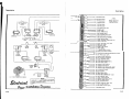
Normal Procedures
310 D
G) a.
Remove controls lock.
® a.
Remove external surface locks. lf installed.
b.
b.
c.
@ a.
~
EXTERIOR
INSPECTION
MotnentarUy turn on battery switch, and check: fuel quantity gages. Check oxygen pressure.
Check general cClnd.ltlon of elevator, rudder and trim tab hinges, hinge bolts and actuator
rod bolts,
Remove tie-down.
b.
Cheek static pressure source hole tor obstruction.
Open baggage door and cheek that oxygen masts and hoses are available. Check cylinder
c.
Close baggage door and check for security.
~hut-off
valve (rear system).
@··
Check aileron and tab hinges, and hince and actuator rod bolts.
®··
Check main fuel tank filler cap and fairing cover for security. On first flight of day, dratn
sump.
@a.
b.
c.
d.
e.
g.
Check auxiliary tank filler cap for security,
Check battery compartment cover panel for security (left side only).
Check anti-ice nuid supply. Check reservoir cover panel lor security (right side only).
Check: auxiliary tank vent lor obstruction.
Check tanding light for damage.
Remove wing tie-down.
On first night of day, drain a.uxiUary tank sump.
a.
b.
c,
Chect oil level. Minimum 9 qua.r>ts; till to 12 quarts lor extended flight.
Chect main landing gear str>ut and tire inflation. ' Check gea.r door lor security.
On first flight of the da.y, drain two ounces of fuel from the strainer.
f.
0
@ a.
b.
c.
@ a.b.
c.
d.
e.
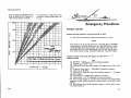
AFTER FAMILIARIZING YOURSELF with the equipment of your airplane, your primary concern will be its operation. ;!This. section. lists, in
Pilot's Check List' form, the normal procedures necessary to operate your
airplane efficiently and safely.
This section is condensed to include only normal "day-to-day flying"
procedures, and is one of your best sources of normal flying information.
It is supplemented by Section III, which contains a narrative description
of operating procedures, and Section IV, which describes emergency procedures. This subdivision of information permits quick and easy reference
to any flight procedure desired.
All airspeeds mentioned in Sections II, Ill, and IV are indicated airspeeds (IAS) with the exception of the Stall Speed Chart on page 3-10 which
is presented in true indicated airspeeds (TIAS). Corresponding true indicated airspeeds may be obtained from the airspeed correction table. in
Section VII.
Check propeller and apinner tor nicks, cracks and security.
Check oU fUler cap for security through cooling air inlet in cowl nose cap.
Check cowl access door& for security.
Chect nose rear strut and tire inflation, nose gear doors !or security,
Chect oxygen cyllnder shutoff valve {forward system),
Check pitot tube opening !or obstructions.
Chect ta.xiltght for damage.
Remove Ue-down.
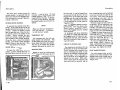
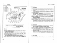
BEFORE ENTERING THE AIRPLANE.
(1) Perform an exterior inspection, following the procedure given in
the diagram on page 1-28.
BEFORE STARTING ENGINES.
(1) Adjust and lock seats in a comfortable position, and fasten safety
belts.
IMPORTANT
After a seat is moved either forward or aft, it should be tested to
see that the latching pins are locked securely.
Repeat steps "4" through "8."
(2) Lock cabin door.
(3) Check controls lock removed.
1-28
2-1
Normal Procedures
Normal Procedures
(4) Check landing gear switch -DOWN.
(5) Battery switch -ON.
NOTE
When using an external power source, do not turn on the battery
until external power is disconnected, to avoid a weak battery draining off part of the current being supplied by the external source.
(6) Generator switches - ON.
NOTE
If 50-ampere generators are installed, turn on one at a time as
the engines are started.
(7) Check circuit breaker panel for faulty circuits.
(8) Landing gear lights -push to test (check iris - open).
(9) Check fuel quantity indicators.
(10) Check left fuel selector valve handle -"- LEFT MAIN; right fuel selector valve handle -RIGHT MAIN (valves in proper detents).
(11) Adjust elevator trim tab position indicator to TAKE-OFF range.
(12) Adjust rudder trim tab position indicator to neutral position.
(13) Adjust aileron trim tab position indicator to neutral and check tab
position visually.
(14) Set altimeter and clock.
(15) Turn off all radio switches.
(16) Release parking brake and test-operate brakes, noting any spongy
action or excessive brake pedal travel.
(17} Check flight controls for free and correct movement.
(18) Set parking brake.
(19) For night flying, test-operate all lights except landing lights.
Make sure an operating flashlight is aboard.
STARTING ENGINE {Left Engine First).
(1)
(2)
(3)
(4)
(5)
Turn ignition switches ON.
Open throttle approXimately 1/2 inch.
Set propeller pitch lever full forward for HIGH RPM.
Set mixture lever full forward for FULL RICH.
Clear the propeller.
(6) Turn the auxiliary fuel pump switch to PRIME position.
NOTE
Avoid leaving the auxiliary fuel pump switch in either the PRIME
or ON position for more than a few seconds unless the engine is
running.
(7) Press starter button when fuel pressure reaches 2 to 2. 5 PSI.
NOTE
If the engines are hot, press starter button first, then turn auxiliary fuel pump switch to PRIME.
(B) Turn off auxiliary fuel pump switch when engine runs smoothly.
NOTE
During very hot weather, if there is an indication of vapor in the
fuel system (fluctuating fuel pressure) with the engine running, turn
the auxiliary fuel pump switch to ON until the system is purged.
(9) Check for an oil pressure indication within 30 seconds in normal
weather and 60 seconds in cold weather. If no indication appears, shut
off engine and investigate.
(10) Disconnect external power source, if used.
WARM-UP AND GROUND TEST (During Taxiing}.
(1) Set both engines at BOO to 1000 RPM.
(2) For night flight, check landing lights.
(3) Turn on radios if required.
(4) Continue the warm -up while taxiing out to the active runway.
(5) Stop airplane at the run-up location with nosewheel straight, and
set parking brake. To avoid propeller tip abrasion, do not run-up
engines on loose cinders or gravel.
(6) Advance throttle to 1700 RPM with control wheel neutral or forward.
(7) Check engine instruments for operation and indication.
(B) Check generator operation by turning off each generator switch
individually and noting amperage.
(9) Check magnetos (125 RPM maximum allowable drop).
(10) Check induction air heat source operation by noting RPM and manifold pressure drop.
2-2
2-3
Normal "Procedures"
Normal Procedures
(11) Place eaeh propeller pifch:lever in the. FEATHER position until
engine speed drops to .1200 RPM, then. return to iulL:forward position.
NOTE
If propeller operation has. been unusually sluggish onerratic, fea-
ther pr.opeller twice to. 600 RPM in· run-up, retarding throttle as
necessary to avoid excessive manifold pressure at low RPM. Exercising. the propeller in this manner insures .opj:imum propeller
governing in flight.
(12) Check operation of•eaeh vacuum pump and ..amount of suction to
the gyros, with·.the .vacuum selector. test valve knob.
(fS)' If each engine accelerates smoothly, and .oHpressure remains
steady at some value between 30 and 60 PSI,' the engines are warm
enough· for take-off.
BEFORE TAKE-OFF OR DURING TAXIING.·.
(1) Recheck elevator trim. tab position indicator for TAKE-OFF range.
(2) Recheck rudder trim tab position indicator for neutral position.
(3) Recheck aileron trim tab ·position indicator·fcirmeutral, and check
tab visually.
(4) Turn auxiliary fuel pump switches to ON.
(5) Check induction air - COLD.
(6} Check free and correct movement of flight•.•conttols.
(7). Check that the,cabin door and the pilot's.window are closed and
locked.
(8) Check and set flight instruments and radio as necessary.
NO'RMAL TAKE-OFF.
(1) Flaps 0 °.
(2) Apply full throttle 'smoothly ;to avoid propeller,·surging.
(3) For maximum-performance, set mixture for.JiiHd elevation.
NOTE
Leaning uring the take'-off roll is normally not. necessary; however,
ould maximum take-off or subsequent..engine-out pernee be deshied,.,ftielpressure should be adj~,Isted to match
'elevation.
{4) Maintain airplane in level attitude in take-off run.
2-4
(5) Keep heels on floor to avoid dragging brakes.
(6) Apply slight back pressure to raise nosewheel as airplane reaches
82 MPH (minimum single-engine control speed).
(7) Plan to break ground at 95 MPH (minimum safe single-engine~
speed).
(8) Apply brakes momentarily to stop wheel rotation.
(9) Retract landing gear.
(10) Accelerate to 111 MPH (best single-engine rate-of-climb speed)\
and climb to a safe single-engine maneuvering altitude.
(11) Accelerate to 119 MPH (best twin-engine rate-of-climb speed).(12) Turn auxiliary fuel pumps OFF individually, checking'final fuel·
pressure indications.
NOTE
During very hot weather, if there is an indication of vapor in the
fuel system (fluctuating fuel pressure) turn the auxiliary fuel pump
ON until cruising altitude has been obtained and the system is
purged.
CLIMB (Twin Engine).
(1) In normal operation, if no obstacle is aheadt .climb. out with flaps
retracted at 130 - 140 MPH, with 24 inches of manifold pressure and
2450 RPM.
(2) Mixture should be adjusted to the hig9,.,.pressure side of the cruise ..
power fuel pressure range for economical fuel consumption in cruising
climb.
(3) For maximum rate-of-climb, use full throttle and 2625 RPrMat
119 MPH, decreasing climb speed to 115 MPH at 10,000 feet.
(4) The mixture should ·be adjusted to the low-pressure side of the
take-off and climb dial range for maximum climb performance.
CRUISING.
(1) Select cruising power setting from range charts (see Section· Vll) ..
Normal cruising power settings are 23 inches and 2300 RPM;' and maximum cruising power settings are 24 inches and 2450 RPM..
(2) After speed is stabilized, trim airplane.
(3) Adjust mixtures to the low-pressure side of the dial.range for•normal operation at the desired power.
(4) Adjust friction knob to prevent engine controls from creeping ..
2-5
Normal Procedures
Normal Procedures
AFTER LANDING.
LET-DOWN.
(1) Reduce power to obtain desired let-down rate at cruising speed.
(2) Set mixture levers full forward (FULL RICH).
(3) For steep let-downs, decrease speed to 160 MPH or less and extend flaps 15°. If necessary, for steeper let-downs, reduce speed
to 140 MPH and extend landing gear.
NOTE
Avoid steep, power-off let-downs with low fuel.
(1) Retract flaps.
(2) Park with nosewheel aligned straight ahead if possible. If gusty
wind conditions prevail, caster the nosewheel to the extreme right or
left position, to protect the rudder from wind damage.
(3) Turn off auxiliary fuel pumps.
(4) Stop engines by putting mixture levers in IDLE CUT-OFF.
(5) After engines stop, turn ignition switches OFF.
(6) Turn all switches OFF.
(7) Set parking brakes.
(8) Install controls lock, if required.
BEFORE LANDING.
(1) Check the left fuel selector valve handle - LEFT MAIN and the
right fuel selector valve handle - RIGHT MAIN.
(2) Check mixture levers full forward (FULL RICH).
(3) Turn on auxiliary fuel pumps.
(4) Check induction air - COLD.
(5) Extend flaps to 15° in small increments below 160 MPH.
(6) Extend landing gear below 140 MPH.
(7) Check green landing gear position indicator light for illumination.
(8) Set propeller pitch levers for 2625 RPM (full forward) for maximum power in case of a go-around.
(9) Lower flaps to 30° - 45° below 140 MPH.
(10) Approach at approximately 95 MPH with or without power.
NORMAL LANDING.
(1) Land on main wheels first.
(2) Lower nosewheel gently to runway after speed is reduced.
(3) Avoid excessive braking unless obstacle is ahead.
GO-AROUND (Twin Engine).
(1) Apply full thrcttle and increase engine speed to 2625 RPM, if necessary.
(2) Reduce flap setting to 15°.
(3) Trim airplane for climb.
(4) Retract flaps as soon as all obstacles are cleared and a safe altitude and airspeed are obtained.
2-6
l
2-7
Normal Procedures
vf/ol1s
..........~HJP..!.LL.. LLL~
+
~
Operating Details
THIS SECTION GIVES, in narrative form, detailed information on those·
check list items in S~ction II that require further explanation.
PREFLIGHT CHECK.
The exterior inspection described
in Section n is recommended for the
first flight of the day. Inspection
procedures for subsequent flights are
normally limited to brief checks of
the tall surface hinges, fuel and oil
quantity, and security of fuel and oil
filler caps. If the airplane has been
in extended storage, has had recent
major maintenance, or has been operated from marginal airports, a
more extensive exterior inspection
is recommended.
Mter major maintenance has been
performed, the flight and trim tab
controls should be double-checked
for free and correct movement and
security. The security of all inspection plates on the airplane should
be checked following periodic inspections. Since radio and heater maintenance requires the mechanic to
work in the nose compartment, the
nose gear doors are often disconnected to allow more room. Therefore, it is important after such maintenance to double-check the security
of these doors. If the airplane has
been waxed or polished, check the
external static pressure source holes
2-8
for stoppage.
If the airplane has been exposed to
much ground handling in a crowded
hangar, it should be checked for
dents and scratches on wings, tip
tanks, fuselage, and tail.surfaces;.
as well as damage to navigation and·'
landing lights, de-icer boots, and
radio antennae. Outside storage for
long periods may result in water andi
obstructions in airspeed system lines,
condensation in fuel tanks, and dust
and dirt on the intake air filters and
engine cooling fins.
If the airplane has been operated
from muddy fields or in snow and
slush, check the main gear wheel
wells and nosewheel mud shield for
obstructions and cleanliness. Opera.tion from a gravel or cinder field
will require extra attention to propeller tips and abrasion on leading
edges of the horizontal tail. Stone
damage to the outer six inches of the
propell~r tips can seriously reduce
the fatigue life of the blades.
Airplanes that are operated from
rough fields, especially at high altitudes, are subjected to abnormal
landing gear abuse. Check frequently
all components of the landing gear
retracting mechanisms, shock struts,
3-1
Operating Details
Operating Details
tires and brakes.
If the airplane is equipped with
auxiliary fuel tanks, make sure that
the filler caps are tightly sealed to
prevent loss of fuel in flight. The
auxiliary fuel tank vents beneath the
wing should also be inspected for obstructions, especially after operation
from muddy fields.
The interior inspection will vary
accord,ing to the mission and the optional equipment installed. Prior to
high-altitude flights, it is important
to check the condition and quantity
of oxygen face masks and hoses. The
oxygen supply system should be functionally checked to insure that it is
in working order. The oxygen pressure gage should indicate between
300 and 1800 PSI depending upon the
anticipated requirements.
Satisfactory operation of the pitot
tube and stall warning tran.smitter
heating elements is determined by
observing a discharge on the ammeter when the pitot heat switch is
turned ON. The effectiveness of
each element may be verified by
cautiously feeling the heat of both
devices while the pitot heat switch is
ON.
Flights at night and in cold weather
involve a careful check of other specific areas that will be discussed in
separate sections.
STARTING ENGINES.
Since the wing obscures ground
crew personnel when they are draining the fuel strainers or connecting
the external power source to the airplane, it becomes doubly-important
to clear the airplane properly be3-2
fore starting. Calling out "clear"
in loud tones or giving a "thumbs up"
hand signal to a responsible ground
crew member is best. An answering "clear" or "thumbs up" hand
signal from visible ground crew personnel is the required response.
Using an external power supply
for starting is recommended in cold
weather, or for airplanes that are
normally used extensively in instrument or night flying. With the external power source connected, it is
preferable to start the airplane with
the battery switch OFF. If the battery switch is ON during the engine
start, weak airplane batteries will
drain off part of the current supplied
by the external power source, resulting in less electrical power available
for the start. After the external
power source is disconnected, the
battery switch should be turned ON
to supply power to electrical equipment.
If 50-ampere generators are installed, turn on each generator after
its engine is started. If both generators are turned on at once before
the engines are started, the paralleling system will reduce the output
from the operating generator.
Although either one may be started first and the procedure is identical
for both, the left engine is normally
started first. The cable from the
battery to this engine is much shorter, which permits more electrical
power to be delivered to the starter.
If batteries are low, the left engine
should start more readily.
Unlike carburetors, which supply
no fuel to the engines until an airflow has been induced by cranking,
the continuous-flow fuel injection
system will start spraying fuel in
the intake ports as soon as the throttle and mixture controls are opened
and the auxiliary pump is turned on.
Thus, fuel injection engines need no
primer; at the same time, if an auxiliary pump is turned on accidentally
while the engine is stopped, with the
throttle open and the mixture rich,
solid fuel will collect in the intake
manifolds, the quantity depending
on the amount of throttle opening
and the length of time the pump has
been operating. If this happens, it
is advisable to wait a few minutes
until this fuel drains away through
the manifold drains before starting
the engine. To avoid flooding, be
sure you are ready to crank the engine before turning on the auxiliary
pump.
If the engines are hot, starting will
be easier and the possibility of flooding will be reduced if the auxiliary
fuel pump is left off until the starter
is turning over the engine. Press
the starter button, then turn on the
auxiliary pump.
Engine mis -starts characterized by
weak, intermittent explosions followed by puffs of black smoke from the
exhaust are the result of flooding or
over -priming. This situation is
more apt to develop in hot weather,
or when the engines are hot. If it
occurs, repeat the starting procedure with the throttle open approximately 1/2, the mixture in idle cutoff and the auxiliary pump off. As
the engine fires, move the mixture
control to full rich and close the
throttle to idle.
If an engine is under-primed, which
may occur in cold weather with a
cold engine, repeat the starting procedure with the auxiliary fuel pump
switch ON until the engine fires.
If prolonged cranking is necessary, allow the starter motor to cool
at frequent intervals, since excessive heat may damage the armature
windings.
TAXIING.
A steerable nosewheel mechanism
provides positive control up to 15 o
left or right, and free turning from
15° to 55° for sharp turns during
taxiing. In addition to the nosewheel
steering, which is preferred whenever practical, steering may be accomplished with the aid of the rudder,
differential power, and differential
braking on the main wheels. These
aids are listed in the preferred order
of use.
IMPORTANT
If the airplane is parked with the
nosewheel castered in either direction, initial taxiing should be
done with caution. To straighten
the nosewheel, use full opposite
rudder and differential power, instead of differential braking. After
a few feet of forward travel, the
nosewheel will steer normally.
At some time early in the taxi run,
the brakes should be tested, and any
unusual reaction, such as uneven
braking, should be noted. If brake
operation is not satisfactory, the
3-3
·operating Details
Operating Details
MINIMUM GROUND CLEARANCE:
PROPELLERS - 9"
airplane should be returned to the
tie-down location and the malfunction
··corrected. The operation of the turnand-bank indicator and directional
gyro should also be checked during
taxiing.
Most of the engine warm-up should
be done during taxiing, with just
3-4
enough power to keep the airplane
moving. Engine speed should not
exceed 1600 RPM while the oil is
cold.
BEFORE TAKE-OFF.
Use the Pilot's Check List in the
airplane for the "before take-off"
check to prevent the possibility of
overlooking an important check item.
Most of the warm ...up will have been
conducted during taxi, and additional
warm -up before .take-off should be
restricted to the checks outlined in
Section II.
Full throttle checks on the ground
are not recommended unless there
is good reason to suspect that the
engines are not turning up properly.
Do not run up the ·engines over loose
gravel or cinders because of possible
stone damage or abrasion to the propeller tips.
If the ignition system check produces an engine speed drop in excess of 125 RPM, continue to warm
up a minute or two longer, before
rechecking the system. If there is
doubt concerning the operation of the
ignition system, checks at higher
engine speed may confirm the seriousness of the deficiency. In general, a drop in excess of 125 RPM
with a warm engine at 1700 RPM is
not considered aceeptable.
If instrument flights are contemplated, a careful check should be
made of vacuum pump operation by
switching the vacuum test selector
valve knob to all positions. The
minimum and maximum allowable
suctions are 4. 75; and 5. 25 inches
of mercury, respectively, on the
instruments. (When the ARC CD-1
Course Director is installed, the
suction limits at the instruments are
3. 8 and 4. 2 inches of mercury). The
gage readings for both source positions should be higher than the gyro
readings. Good generator condition
is also important for instrument
flight since satisfactory operation of
all radio equipment and electrical
instruments is essential. The generators are checked by observing
the charging .rate on the ammeter
during an engine run-up to 1700 RPM
while the generator on the opposite
engine is switched off momentarily.
A simple last minute recheck of
important items should include a
quick glance to see that the top row of
switches on the left switch panel are
ON, the mixture and propeller pitch
levers are forward, all flight controls have free and correct movement, and the fuel selectors are
properly positioned.
TAKE-OFF.
Since the use of full throttle is not
recommended in the static run-up,
closely observe full-power engine
operation early in the take-off run.
Signs of rough engine operation, unequal power between engines, or
sluggish engine acceleration are good
cause for discontinuing the take-off.
If this occurs, you are justified in
making a thorough full throttle static
run-up before another take-off is attempted.
Normal take-offs are conducted
with flaps retracted to provide maximum safety in case of an engine failure after take-off. The distance
required to clear a 50-foot obstacle,
after an engine failure, at 95 MPH
with flaps retracted is only approximately 60 percent of the distance
required with flaps 15 degrees. The
distance to decelerate to a stop from
any given speed is also shorter, and
3-5
Operating Details
Operating Details
there is less chance of tire damage
with heavy braking since more weight
remains on the main wheels with
flaps retracted.
Full throttle operation is recommended on take-off since it is important that a speed well above minimum single-engine control speed
(82 MPH) be obtained as rapidly as
possible. It is desirable to accelerate the airplane to 95 MPH while still
on the ground for additional safety
in case of an engine failure. This
safety may have to be compromised
slightly where short and rough fields
prohibit such high speed before takeoff.
In order to obtain maximum engine
power for take-off and climh out,
adjust the mixture controls during
the initial take-off roll to the lowpressure side of the dail range corresponding to the field elevation.
While the performance increase obtained by leaning will be small at
low altitudes, it will become greater
as field elevation increases. Consequently, this technique should always be employed when operating
from field elevations greater than
5000 feet above sea level. If you are
familiar with typical mixture lever
positions on the quadrant for best
power mixture at various field elevations for your particular airplane,
you may preset the mixture controls
before take-off. However, these
positions will vary between airplanes
because of fuel metering and mixture control rigging tolerances.
After take-off it is important to
maintain the minimum safe singleengine climb speed (95 MPH). As
you accelerate still further to best
single-engine rate-of-climb speed
(111 MPH), it is good practice to
climb rapidly to an altitude at which
the airplane is capable of circling
the field on one engine.
NOTE
For take-offs at high density altitudes, above the single-engine
service ceiling, the allowance
must be enough to clear obstacles
in single-engine drift-down flight.
Mter obstruction height is reached,
power may be reduced and climb
speeds may be established as described in Section ll.
On long runways, the landing gear
should be retracted at the point over
the runway where a wheels -down
forced landing on that runway would
become impractical. However, on
short runways it may be preferable
to retract the landing gear immediately after reaching 95 MPH.
The use of 15° flaps reduces the
ground run and the total distance
over a 50-foot obstacle by approximately 13 percent. Minimum-run
and soft-field take-offs are performed with flaps 15" by lifting the nosewheel as the airspeed approaches
60 MPH, so that the airplane will
leave the ground in a tail-low attitude. However, the airplane should
be immediately leveled off and accelerated to 95 MPH as rapidly as
possible.
Obstacle clearance take-offs from
soft fields are conducted in the same
manner except that a climb at 85
MPH is established after take-off.
From hard-surface runways the air-
plane will climb at a given airspeed
over an obstacle in approximately
the same total distance using any
lift-off speed between 65 and 85 MPH.
The best technique is to lift off as the
airspeed approaches 80 MPH, and
then establish an 85 MPH climb.
Performance data for this type of
take-off is presented in Section VII.
Crosswind take-offs are performed
with a minimum flap setting necessary for the runway length, to mintmize the drift angle after take-off.
Additional power may be carried on
the upwind engine until the rudder
becomes effective. The airplane is
accelerated to a slightly higher than
normal take-off speed, and then is
pulled off abruptly to prevent possible settling back to the runway
while drifting. When clear of the
ground, a coordinated turn is made
into the wind to correct for drift.
A take-off with one tip tank full and
the opposite tank empty creates a
lateral unbalance at take-off speed.
This is not recommended since gusty
air or premature lift-off could create
a serious control problem.
AFTER TAKE-OFF.
To set up the airplane in climb
configuration, retract the landing
gear, adjust power for climb, retract the flaps (if used) at a safe altitude and airspeed, turn off the auxiliary fuel pumps, and adjust the
mixture for the power setting selected.
Power reduction will vary according to the requirements of the traffic
pattern or surrounding terrain, gross
weight, field elevation, temperature,
and engine condition. However, a
normal "after take-off" power setting
is 24 inches of manifold pressure and
2450RPM.
Before retracting the landing gear,
apply the brakes momentarily to
stop the main wheels. Centrifugal
force caused by the rapidly-rotating
wheels expands the diameter of the
tires, and if ice or mud has accumulated in the wheel wells, the rotating
wheels may rub as they enter.
CLIMB.
A cruising climb at 24 inches of
manifold pressure, 2450 RPM (approximately 75% power) and 130 to
140 MPH is recommended for saving
time and fuel for the overall trip. In
addition, this type of climb provides
better engine cooling, less engine
wear, and more passenger comfort
due to lower noise level. The mixture should be leaned in this type of
climb to give fuel pressures on the
high-pressure side of the cruising
power dial range, which is approximately best-power mixture. At this
setting, maximum performance for
the power selected will be obtained
without the high fuel consumption required for cooling at higher powers
and lower climb speeds.
If it is necessary to climb rapidly
to clear mountains or reach favorable winds at high altitudes, the best
rate-of-climb speed should be used
with maximum power. This speed
varies from 119 MPH at sea level
to 114 MPH at 15, 000 feet. During
maximum-performance climbs the
mixture should be leaned to give fuel
3-6
3-7
Operating Details
Operating·Details ·
pressures on the low-pressure side
of the take-off and climb dial range
to assure maximum.p~wer and adequate engine cooling.
If' an obstruction ahead requires
a steep. climb angle, the airplane,
should be flown at ·the best angle ..ofclimb speed with flaps up and maximum p9Wer. This·speed varies··from
97 MPH'at sea level.hll l06·. MP.H at
15,000 feet.
CRUISE.
Tabulated cruising information for
normal cruising power and altitudes
is presented in Section VII. These
charts are based on 100 and 130 gallons of fuel for cruise; normal lean
mixture, 4830 pounds gross weight,
zero wind, and no fuel reserve. Allowances for warm-up, take-off and
climb, headwinds, variations in mixture leaning technique, and fuel reserve should be estimated; and the
endurance and range shown in the
charts should be modified accordingly. Fuel allowances for take-off
and climb are given in the climb
charts on page 7-3.
Since one of the main advantages of
the airplane over ground transportation is speed, one should use the high
cruising speeds obtainable. However, if a destination is slightly out
of reach in one flight at normal cruising speed, it may save time and money to make the trip nonstop at some
lower speed. The cruising charts
show the long ranges.;obtainable at
lower cruising speeds•
Normal cruising is done.between
60% and 70% power. The manifold
pressure and RPM settings required
3-8
to obtain these ppwers at various
altitudes and outside air temperatures can be determined with your
Cessna . 310 Power Computer. A
maximum cruising power of aPproximately 75% is allowable with 24 inches of manifold pressure and. 2450
RPM.
To achieve the level flight performance shown in the·cruising charts in
Section vn, lean the mixtures to give
fuel pressures on the low-pressure
side of the cruise power dial range
for the desired power. This should
result in normal lean mixtures which
will yield airspeeds only slightly
below those available at best power
mixture but with considerably lower
fuel consumption and, consequently,
longer raJ?.ge. This leaning technique offers an optimum compromise
between speed and range for normal
cruising flight.
Should maximum speed be desirable
for short flights where range and fuel
consumption are less important, the
mixture should be leaned to the highpressure side of the cruise power
dial range. This will yield approximately best-power. mixture with a
resulting airspeed of one to two MPH
greater and a fuel flaw approximately
two gallons per hour greater than
those listed in Section VII.
If maximum range is desired, the
mixture should be.•:leaned approximately one PSI below the low-pressure edge of the dial range for the
power utilized. This should result
in airspeeds approximately 5 MPH
lower than those listed in Section VII
but with an increase.of approximately
150 miles in range. At normal cruise
power (below 75% ·power), operation
'
I
1
J
!
.
'I
l
•
•'
I
at a maximum-range mixture setting
is not detrimental to engine life providing that the engines are running
smoothly and the cylinder head ternperatures are maintained in appro ximately the middle of the green arc
range.
For a given throttle setting, select
the lowest engine speed in the green
arc range that will give smooth engine operation without evidence of
laboring.
Synchronize the propellers by setting one propeller at the desired engine speed, turning the friction control knob to prevent propeller pitch
lever creep, and then adjusting the
other propeller pitch lever until the
tachometer needles are aligned one
over the other. If synchronization
is slightly off, as indicated by an
intermittent ''beat", one propeller
pitch lever should be adjusted to
eliminate this beat. Synchronization is simplified by limiting the
adjustments to only one propeller.
To avoid slack in controls, the final
movement of the lever should be
made in a DECREASE RPM direction.
In airplanes equipped with auxiliary
fuel tanks, it is important to burn
approximately one hour of fuel from
the main tanks before switching to
auxiliary tanks. This is necessary
to provide space for approximately
7 gallons of auxiliary fuel and vapor
that are returned through vapor return lines to the main tanks. If sufficient space is not available in the
main tanks for this diverted fuel, the
tanks may overflow through the filler
cap vent hole. Since part of the fuel
from the auxiliary tanks is diverted
back to the main tanks instead of
being consumed in the engine, these
tanks will run dry sooner than may
be anticipated. However, the main
tank endurance will be increased by
the returned fuel.
Since the auxiliary fuel tanks are
designed for cruising flight, they
are not equipped with pumps. Under
cruising conditions, failure of an
engine-driven fuel pump will not be
critical because there will be ample
time to switch on the main fuel tank
and turn on the auxiliary fuel pump.
However, operation near the ground
using auxiliary fuel tanks is not recommended because of this limitation.
The fuel injection system employed
on these engines is considered to be
non-icing. In addition, the internal
location of the induction air inlets
should preclude the possibility of
impact ice covering the intake air
filters. Induction air heat is incorporated, however, to assure satisfactory operation in the unlikely event
that unusual atmospheric conditions
should cause intake system icing.
The induction air handles should be
left in the full cold position for all
normal operations. Should intake
system icing be encountered, the
handles should be pulled to the full
heat position.
FLIGHT CHARACTERISTICS.
The stability and control characteristics of the airplane are very satisfactory. Control forces are light
and adequate control is available
throughout the operating speed range.
When properly trimmed, the airplane
will remain in straight and level
3-9
Operating Details
Operating Details
~~:::::::::STALL
SPEED
CHART====~===
MPH- TIAS
4830 POUNDS GROSS WEIGHT
SPINS.
::::::::::::::;:;:;:;:;:;::::::::~:;:;:;:;:;:;:;:;:;:;:~;:;:;:;:;:;::::.;::::~;:;::::i::::::::::;:;:;:;:;:::;:;:;:::::::::;:;:::::::::;:;:::::;:;:::::::::~:::::~~:;:;:;:;:;~:;:;:;:;:~::::;:::;:;:;:;:;::::::::::::~:;:::::::;:;:;:;:::::::::::::::;:::::;:;:;
oo
Angle of Bank
20°
40°
Gear and Flaps Up
84
87
96
119
Gear Down and Flaps 15"
80
83
92
113
Gear Down and Flaps 45"
74
77
85
105
Configuration
flight with little attention from the
pilot.
NORMAL STALLS.
The stall characteristics of the
airplane are conventional in all configurations. Aural warnings are
provided by the stall warning horn
between 5 and 10 MPH above the stall
in all configurations. The stall is
also preceded by a mild aerodynamic
buffet which increases in severity as
the stall is approached. The poweron stall occurs at a very steep angle
either with or without flaps, and it
is difficult to inadvertently stall the
airplane during normal maneuvering.
The stall characteristics in all configurations are characterized by a
clean drop of the nose accompanied
by increased buffet during the stall.
The rudder should be used to prevent yaw during the approach to the
3-10
the airplane will be exceeded if accelerated stalls are performed above
163 MPH.
60°
stall since a rolling tendency will
result if the airplane is allowed to
yaw. Recovery is made very quickly with little loss of altitude if the
nose is not lowered excessively and
full available power is applied to
both engines. Landing gear and flap
position have little effect on the stall
characteristics except that the stalling speed will be lowered in proportion to the degree of flap extension.
Power-off stall speeds at maximum
gross weight are presented as true
indicated airspeeds in the stall speed
chart because indicated airspeeds
are inaccurate near the stall.
ACCELERATED STALLS.
Stalls in accelerated flight are preceded by stall warning horn indications, and by light aerodynamic buffet. The structural limitations of
Intentional spins are not permitted
in this airplane, and due to the excellent stall warning system provided, it is not probable that an inadvertent spin will be encountered.
Should a spin occur, however, the
following recovery procedure should
be employed:
(1) Cut power on both engines.
(2) Apply full rudder opposing the
direction of rotation.
(3) Approximately 1/2 turn after
applying rudder, push control wheel
forward briskly.
(4) To expedite recovery, add power
to the engine toward the inside of
the direction of turn.
(5) Pull out of dive with smooth
steady control pressure.
comparatively light, and only slight
rudder pressure is required when
rolling into and out of turns. All
trim tabs are effective throughout
the speed range of the airplane, the
rudder and elevator trim becoming
very effective at cruising airspeeds.
LEVEL FLIGHT CHARACTERISTICS UNDER VARIOUS SPEED CONDITIONS.
The airplane flight characteristics
throughout the level- flight speed
range are conventional in all respects.
Slow flying is easily accomplished
with wing flaps up or down and landing gear up or down.
MANEUVERING FLIGHT.
No acrobatic maneuvers are approved in this airplane. The airplane is, however, conventional in
all respects throughout the maneuvering range encountered in normal
flight.
FLIGHT CONTROLS.
Elevator control forces are relatively light in cruising flight at all
airplane loadings. Reducing power
and extending the flaps and landing
gear increases the elevator control
forces appreciably thereby enhancing the control feel at low airspeeds.
Aileron control forces are light, and
aileron control is much more effective than is at first apparent from
control feel. This is more pronounced at slow speeds with full wing tip
(main) tanks, where the time response to aileron deflection is increased slightly. Rudder forces are
DIVING.
Dives should be limited to the maximum diving airspeed marked on the
airspeed indicator (248 MPH}. Although trim changes and flight characteristics are conventional, caution
should be exercised because the airplane picks up speed rapidly, and if
rough air is encountered unexpectedly, it is difficult to slow the airplane down to a safe speed. Pullouts should be very gentle to avoid
excessive stresses in the airplane
as well as discomfort to the passengers.
3-11
Operating Details
Operating Details
LET-DOWN.
Let-downs should be initiated as
much as an hour before estimated
landing time to permit a gradual
rate of descent at cruising speed
using enough power to keep the engines warm and the cylinders clear.
Since the airplane is so aerodynamically clean it is difficult to descend rapidly without reducing power
to very low settings. This results
in undesirably low cylinder head
temperatures, which in turn lead to
spark plug fouling. The optimum
engine speed in a let-down is usually
the lowest one in the RPM green
arc range that will allow cylinder
head temperatures to remain in the
recommended operating range.
BEFORE LANDING.
If fuel has been consumed at uneven rates between the two main
tanks because of prolonged singleengine flight, it is desirable to balance the fuel load by operating both
engines from the fullest tank. However, if there is sufficient fuel in
both tanks, even though they may
have unequal quantities, it is important to switch the left and right
selector valves to the left and right
main tanks respectively for the landing. This will provide an adequate
fuel flow to each engine if a fullpower go-around is necessary. In
airplanes equipped with auxiliary
fuel tanks, the selector valves should
be switched to main tanks for landing
because the auxiliary tanks are not
equipped with auxiliary fuel pumps.
Landing gear extension before land-
3-12
ing is easily detected by a slight
change in airplane trim and a slight
"bump" as the gear locks down. illumination of the gear -down indicator
light {green), is further proof that
the gear is down and locked. H it is
reasonably certain that the gear is
down and the gear -down indicator
light is still not illuminated, the malfunction could be caused by a burned
out light bulb. This can be checked
by pushing to test. If the bulb is
burned out it can be replaced with
the bulb from either the compass
light, turn-and-bank test light, or
the landing gear up (red) indicator
light.
A simple last-minute recheck on
final approach should confirm that
the top· row of switches on the left
switch and control panel are ON,
the gear -down indicator light (green)
is illuminated, and the propeller
pitch levers and mixture levers are
full forward.
LANDING.
Landings are simple and conventional in every respect. If power is
used in landing approaches it should
be eased off cautiously near touchdown because the "power-on" stall
speed is considerably less than the
"power -off" stall speed. An abrupt
power reduction at five feet altitude
could result in a hard landing if the
airplane is near stall speed.
Short-field landings on hard-surface
runways are performed with 45 o flaps
from an 80 to 90 MPH approach, using as little power as practicable.
A normal flare- out is made, and
power is reduced in the flare-out.
The landing is made on the main
wheels first, and remaining engine
power is cut immediately after touchdown. The nosewheel is quickly
lowered to the ground and heavy braking is applied as required. Short
field landings on rough or soft runways are done in a similar manner
except that the nosewheel is lowered
to the runway at a lower speed to
prevent excessive nose-gear loads.
Crosswind landings are performed
with the least effort by using the
crab method. However, either the
wing-low, crab, or combination method may be used. Crab the airplane
into the wind in a normal approach
using a minimum flap setting for the
field length. Immediately before
touchdown, the airplane is aligned
with the flight path by applying downwind rudder. The landing is made
in a nearly three-point attitude, and
the nosewheel is lowered to the runway immediately after touchdown.
A straight course is maintained with
the steerable nosewheel and occasional braking if necessary.
AFTER LANDING.
Heavy braking in the landing roll
is not recommended because skiding the main wheels is probable,
with resulting loss of braking effectiveness and damage to the tires.
It is best to leave the flaps fully extended throughout the landing roll
to aid in decelerating the airplane.
After leaving the active runway, the
flaps should be retracted. Be sure
the flaps switch is identified before
placing it in the UP position. The
auxiliary fuel pump switches nor-
mally are turned OFF while taxiing
to the hangar, except in extremely
hot weather when auxiliary fuel pumps
may be needed to maintain steady
fuel pressures.
Parking is normally accomplished
with the nosewheel aligned straight
ahead. This simplifies the steering
during subsequent departures from
the parking area. However, if gusty
wind conditions prevail, .the nosewheel should be castered to the extreme right or left position. This
forces the rudder against the rudder
stop which reduces buffeting of the
rudder in gusty wind.
With the mixture levers in IDLE
CUT -OFF, the fuel flow is effectively blocked at the fuel metering
body. Thus, it is unnecessary to
place the fuel selector valve handles in the OFF position if the airplane is receiving normal usage.
However, if a long period of inactivity
is anticipated, the fuel selector valve
handles should be turned OFF to preclude any possible fuel seepage that
might develop through the metering
valve.
NIGHT FLYING.
Before starting the engines for a
night flight, the rheostats located
on the left switch and control panel
and on the overhead console panel
should be turned on and adjusted to
provide enough illumination to check
all switches, controls, etc. In addition, the dome lights may be used
if desired.
Navigation lights are then checked
by observing illumination in the small
peep holes in the inboard leading
3-13
Operating Details
Operating Details
edges of the wing tip tanks and re. flection from the pavement or ground
· below the taillight. The retractable
landing lights (the right landing light
is optional equipment) may be extended and checked momentarily. Returning the landing light switches to
OFF turns the lights off but leaves
them extended ready for instant use.
Before taxi, the interior lighting
intensity is normally decreased to
the minimum at which all the controls and switches are visible. The
optional taxi light, if installed, should
be turned on prior to taxiing at night.
The landing lights, if used during
taxiing, should be used intermittently to avoid excessive drain on
the batteries. Taxiing over loose
gravel should be avoided with the
landing lights extended. In the engine run-ups, special attention should
be directed to generator operation
by individually turning the generator
switches OFF and ON and noting the
response on the ammeter.
Night take-offs are conventional,
although the gear retraction operation is usually delayed slightly to
insure that the airplane is well clear
of the runway. The landing lights,
if used, should be retracted before
the airspeed exceeds 160 MPH.
In cruising flight, the interior lighting intensity is usually decreased
further for better outside vision.
to the higher cranking power required,
coupled with the decreased battery
output at low temperatures.
When very cold temperatures are
anticipated, oil dilution should be
employed before stopping the engines, if external preheat is not available. The starting procedure
is normal, although if the engines
do not start immediately, it may be
necessary to switch the auxiliary
fuel pumps to ON for a few seconds.
The use of external preheat will
considerably improve cold-weather
starting and materially reduce the
severity of conditions imposed on
both the engines and the electrical
system. Preheat also will thaw the
oil trapped in the oil cooler which
will probably be congealed prior to
starting in very cold temperatures.
Take-off procedures are normal
in all respects.
landing with the alternate source
valve open and the pilot's storm window closed, fly at an indicated airspeed 10 MPH faster and altitude 30
feet higher than normal. During
landings with the static source valve
open and the pilot's storm window
open make these allowances 26 MPH
and 160 feet.
CLIMB AND CRUISE.
OIL DILUTION OPERATION.
At half-hour intervals, the propellers should be exercised to flush
the cold oil from the governors and
propeller hubs. Electrical equipment should be managed to assure
adequate generator charging throughout the flight, since cold weather
adversely affects battery capacity.
If your airplane is equipped with
an optional oil dilution system and
very low temperatures are expected,
dilute the oil in each engine before
stopping the engines. Determine
the dilution time required for the
anticipated temperature from the on
Dilution Table on page 3-16. With
the engines operating at 1000 RPM,
and the auxiliary fuel pumps in the
ON position, hold the oil dilution
switch to L (left engine) and R (right
engine) for the necessary time. Fuel
will flow into the oil pump of the engine receiving dilution, at the rate of
1 quart every two minutes. Diluting
the oil in each engine for eight minutes (4 quarts of fuel) is considered
maximum.
While diluting the engine oil, watch
the oil pressure closely. A slight,
gradual pressure drop is to be expected as the oil is thinned. Stop
the engine, however if any sharp
fluctuation in pressure is observed;
it may be caused by an oil screen
becoming clogged with sludge washed
down by the fuel.
warm the governor and propeller
hub. The engines should accelerate
smoothly and oil pressure should remain normal and steady.
TAKE-OFF.
WARM-UP.
LET-DOWN AND LANDING.
ENGINE OPERATION IN
COLD WEATHER.
If the oil pressure gage is extremely slow in indicating pressure, it
may be advisable to fill the pressure
line to the gage with kerosene. No
temperature indication need be apparent on the oil temperature gage
prior to take-off if outside air temperatures are very cold. After a
suitable warm-up period (2 to 5 minutes at 1000 RPM if preheat is not
used), accelerate the engines several
times to higher RPM. If the engines
accelerate smoothly and the oil pressure remains normal and steady, the
airplane is ready for take-off.
STARTING.
BEFORE TAKE-OFF.
During let-down, watch engine tempez:atures closely and carry sufficient
power to maintain them above operating minimums.
If erroneous instrument readings
are suspected due to water or ice
in the static -pressure lines, the
static- pressure alternate- source
valve should be opened. Since this
valve vents to the relatively -low
static pressure of the cabin, the airspeed indicator and altimeter will
show slightly higher readings than
normal. Therefore, the alternate
static source should be used primarily as a drain valve to restore the
original system.
If the alternate static source must
be used for instrument operation,
compensation should be made in indicated airspeeds and altitudes. In
Whenever possible, external power
should be used in cold weather, due
The propeller should be operated
through several complete cycles to
NOTE
When the dilution system is used
3-14
3-15
Operating Details
Operating Details
I
1
OIL DILUTION TABLE
TEMPERATURE
0°F
Dilution Time
Fuel Added
•
I
-10°F
!
-20°F
2 min.
5 min.
8 min.
1 qt.
2.5 qt.
4qt.
MAXIMUM SUMP CAPACITY--16 qt.
MAXIMUM FOR TAKE-OFF-- 13 qt.
for the first time each season,
the oil should be changed and the
oil screens cleaned to remove
sludge accumulations washed down
by the fuel. Use the full dilution
period, drain the oil, clean the
screens, refill with new oil and
redilute as required for the anticipated temperature before the
engine has cooled completely.
On starting and warm -up after diluting the oil, again watch the oil
pressure closely for an indication
of sludge blocking the oil screens.
If the full dilution time was used,
starting with full sumps, run the engines long enough to evaporate some
of the fuel and lower the sump level
to 13 quarts before take-off. Otherwise, the sumps may overflow when
the airplane is nosed up for climb.
To avoid progressive dilution of the
oil, flights of at least an hour should
be made between oil dilutions.
PilOT AND STALL WARNING HEATER OPERATION.
At least five minutes before entering a potential icing condition, turn
3-16
on the_pitot and stall warning heater
switch, so these units will be warm
enough to prevent formation of ice.
Preventing ice is preferable to attempting its removal once it has
formed.
PROP'ELLER ANTI-ICE SYSTEM OPERATION.
To operate the propeller anti-ice
system, proceed as follows:
(1) Anti-ice switch -ON (up position).
(2) Anti-ice knob - MAX (turned
full clockwise) for one minute to wet
blades just before entering suspected icing conditions.
(3) Anti-ice knob - 1.\tliN (counterclockwise position) and note sound
of ice against the fuselage.
NOTE
A slushing sound against the fuselage is desired, and fluid should
be added if necessary until the
slushing sound is heard. Sharp
bangs indicate that the ice is solid
and more fluid is required.
Under average icing conditions,
the above procedure will provide
approximately one-half hour of antiicing before the fluid supply is exhausted.
HEATER OPERATION FOR
HEATING AND DEFROSTING.
The heater is operated for heating
and windshield defrosting in accordance with the following steps:
(1) Battery switch - ON.
(2) Cabin air knob- Full out.
(3) Defrost knob - Adjust as desired.
(4) Cabin air temperature control
knob - Full clockwise to MAX.
(5) Cabin heater switch -HEAT.
(6) Heat registers - Open (as desired).
NOTE
Warm air should be felt coming
out of the cabin heat registers
within approximately one minute.
If the heater does not start, return the heater switch to the OFF
position, anq check the circuit
breaker labeled CABIN HEAT.
Place the cabin heater switch in
the HEAT position and attempt
another start. If the heater still
does not start, service is required
and no further starting attempt
should be made.
(7) Cabin air temperature control
knob - Adjust as desired (after
heater has been operating for one
minute).
(8) To shut down the heater, place
the cabin heater switch in the OFF
position.
OXYGEN SYS. OPERATION.
The oxygen system operation is
automatic in that no manual regulation is required to compensate for
changes in altitude, or to shut off
the -oxygen flow when the system is
not in use. To operate the system,
proceed as follows:
Before Flight:
(1) Oxygen cylinder shut-off valve
- Check open (valve handle rotated
full counterclockwise).
(2) Oxygen pressure gage - Check
for sufficient pressure for anticipated requirements of flight (see
Oxygen Duration Chart, page 3-18.)
During Flight:
(1) Mask and hose -Select from
plastic bag on utility shelf. If mask
and hose are not connected, attach
, by inserting short plastic tube on
' mask securely into end of rubber
hose.
(2) Mask - Put on.
IMPORTANT
Permit no smoking when using
oxygen. Oil, grease, soap and
other fatty materials in contact
with oxygen constitute a serious
fire hazard. Be sure hands and
clothing are free from oil before
handling oxygen equipment.
(3) Hose coupling - Plug in overhead console.
(4) Oxygen flow indicator -Check
3-17
Operating Details
that red indicator disappears when
hose is inserted into coupling, to
insure that oxygen is flowing.
(5) Disconnect mask hoses from
overhead console panel when not
in use.
..........dt.JJP..!.tL.. .tv..... 4- .
Emergency Procedures
1500 I
I
I
I
ENGINE FAILURE.
1;;;
-=.,;
ENGINE FAILURE DURING TAKE-OFF BELOW 95 MPH .
a:
(1) Cut power on operative engine and decelerate to a stop.
w
1000 I
I
NOTE
I
«
::I
The airplane can be accelerated from a standing start to 95 :MPH
on the ground, and then decelerated to a stop with heavy braking
within 2500 feet of the starting point of the take-off run at sea level,
and within 3300 feet of the starting point at 5000 feet altitude (zero
wind, hard surface runway, standard conditions, full gross weight) .
Ill
Ill
w
CODE
«
a.
...C>
500
c(
C>
.,
0r
0
3-18
1
1
I
!OXYGEN SYSTEM DURATION CHART
1
1
2
1
1
1
1
3
4
.DURATION -
1
1
1
5
(HOURS)
1
6
1
1
7
1
ENGINE FAILURE AFTER TAKE-OFF ABOVE 95 MPH WITH ROUGH
TERRAIN AHEAD .
1
(1) Throttles -FULL FORWARD.
(2) Propeller pitch levers - FULL INCREASE RPM.
(3) Landing gear switch - UP.
(4) Determine the inoperative engine (idle engine same side as idle
foot).
(5) Propeller pitch lever - FEATHER {inoperative engine).
(6) Climb out at 95 MPH.
(7) Trim tabs -Adjust for climb with airplane banked 3° - 5° toward
operative engine.
(8) Accelerate to 111 MPH after obstacle is cleared.
(9) Flaps switch -UP (if extended) in small increments.
(10) Secure dead engine by turning OFF auxiliary fuel pump switch,
generator switch, ignition switches, mixture lever, fuel selector valve
handle.
(11) Fuel selector valve handle (operative engine) -Select tank to maintain lateral balance.
4-1
Emergency Procedures
SUPPLEMENTARY INFORMATION
CONCERNING ENGINE FAILURE
DURING TAKE-OFF.
The most critical time for an engine to fail in a twin-engine airplane
is during a two- or three -second
Emergency Procedures
period late in the take-off run while
the airplane is accelerating to a safe
engine-out climb speed. A detailed
knowledge of recommended singleengine airspeeds in the table below
is essential for safe operation of this
airplane:
SINGLE-ENGINE AIRSPEED NOMENCLATURE
lAS-MPH
·:·:·:·:·:-:-:-:-:-:·:·:·:-:·:·:·:·:·:·:·:·:·:·:·:·:·:·:·:·:·:·:·:·:·:·:·:·:·:·:·:·:·:·:·:·:·:·:·:·:·:·:·:·:·:·:·:·:·:·:·:·:·:·:·:·:·:·:·:-:-:·:·:·:·:-:-:-:-:·:·:·:·:·:·:·:·:·:·:·:·:·:·:·:·:·:·:·:·:-:-;.;.;.;.;.;.:-:·:·:·:·:·:·:·:·:-:=:·:·:::·:=:·:·:·:·:·:-:-:-:-:-:-:-:·:·:·:·:·:·:·:-:-:-:-:-:·:·:·:·:·:·:·:·:·:·:·:·:·
1. Minimum control speed ............................................ 80
2. Minimum safe climb speed ............................... , ....... 95
3. Best angle-of-climb speed ....................................... 95
4. Best rate-of-climb speed (flaps up) ........................... 111
(tt:~::=~=~r~ttt~=:=t=:~:t====t:===~''''''''''''''tt=:::::::::::=::=::=:=:===::::::rtt::::::t}'''''?tt:t:=:=:::=:::::::::::::~tt:ttt:::~:::::::=t=~=:=:t:::::t::::::::::::::::::::=:::::::=t::::=::::::::::m~=::::::::~::ti
These speeds should be memorized for instant recollection in an emergency, and it is worthwhile toreview them mentally, prior to every
take-off. The following paragraphs
present a detailed discussion of the
problems associated with engine
failures during take-off.
A multi- engine airplane has an
advantage over a single-engine airplane only after the engine-out minimum control speed is reached. This
speed is defined as the minimum
speed at which controlled flight is
maintained with one engine inoperative, and full power operation on the
other engine. Under these conditions,
full control surface deflection of any
one control is normally required to
counteract extreme yawing and rolling tendencies of the airplane. This
airplane has an engine-out minimum
control speed of 80 MPH. Since
this speed is so far below the optimum climb speed, it is not suitable
for single-engine operation near the
ground, especially with the landing
4-2
gear and flaps extended and the inoperative propeller windmilling. A
more suitable minimum safe singleengine climb speed is 95 MPH, since
at this speed altitude can be maintained more easily while the landing gear is being retracted and the
propeller is being feathered.
The best angle-of-climb speed for
single-engine operation is defined
as the speed which gives the greatest increase in altitude in a given
distance. This speed becomes important when there are obstacles
ahead on take-off, because once the
best single-engine angle -of-climb
speed is reached, altitude becomes
more important than airspeed until
the obstacle is cleared. The best
single-engine angle-of-climb speed
is approximately 98 MPH with flaps
up and 91 MPH with flaps 15° for an
average single-engine altitude. For
convenience, a speed of 95 MPH may
be used for any flap setting between
0 - 15 o, since it is an average speed
which also is identical to the recom-
mended minimum safe single-engine
climb speed.
The best rate-of-climb speed for
single-engine operation is defined
as the speed that gives the greatest
increase in altitude in the least time.
This speed becomes important when
there are no obstacles ahead on takeoff, or when it is difficult to maintain or gain altitude in single-engine
emergencies. The best single-engine
rate-of-climb speed is 111 MPH with
flaps up, and 101 MPH with flaps 15°
at sea level. The flaps-up speed at
111 MPH is of primary importance,
because rate-of-climb is appreciably
greater with flaps up than with flaps
15 o. The variation of flaps-up best
rate-of-climb speed with altitude is
shown in Section VII. For best climb
performance, the wings should be
banked 5° toward the operative engine.
Upon engine failure after reaching
95 MPH on take-off, the twin-engine
pilot has a significant advantage over
a single-engine pilot, for he has the
choice of stopping or continuing the
take-off. This would be similar to
the choice facing a single- engine
pilot who has suddenly lost slightly
SINGLE
more than half of his take-off power.
In this situation, the single-engine
pilot would be extremely reluctant
to continue the take-off if he had to
climb over obstructions. However,
if the failure occurred at an altitude
as high or higher than surrounding
obstructions, he would feel free to
maneuver for a landing back at the
airport.
Fortunately the Cessna 310D accelerates through this area where the
airplane is "slow and low" in just a
few seconds. However, to make an
intelligent decision in this type of
emergency, one must consider field
length, obstruction height, field elevation, air temperature, headwind,
and gross weight. The flight paths
illustrated in the figure below· indicate that the "area of decision" is
bounded by: (1) the point at which
95 MPH is. reached and (2) the point
where obstruction altitude is reached. An engine failure in this area
requires an immediate decision.
Beyond this area, the airplane, within the limitations of single-engine
climb performance shown in Section
Vll, may be maneuvered to a landing back at the airport.
ENGINE TAKE-OFF
_.-
I
ACCELERATE -STOP DISTANCE
TOTAL TAKE • OFF DISTANCE OVER OBSTACLE
--
.... '
a
I,,,.
.
4-3
Emergency Procedures
Emergency Procedures
At sea level, with zero wind and
4830 pounds gross weight, the distance to accelerate to 95 MPH and
stop is 2390 feet, while the total
unobstructed area required to takeoff and climb over a 50-foot obstacle
after an engine failure at 95 :MPH is
2265 feet. This total distance over
an obstacle can be reduced appreciably under more favorable conditions of gross weight, headwind, or
obstruction height, However, it is
recommended that in most cases it
would be better to discontinue the
take-off, since any slight mismanagement of single-engine procedure
would more than offset the small
distance advantage offered by continuing the take-off. The advantage
of discontinuing the take-off is even
more obvious at a 3000-foot field
elevation where the corresponding
distances are 2800 feet and 3295
feet, respectively. Still higher field
elevations will cause the engine-out
take-off distance to lengthen disproportionately until an altitude is
reached where a successful takeoff is improbable unless the airspeed and height above the runway
at engine failure are great enough
to allow a slight deceleration and
altitude loss while the airplane is
being prepared for a single-engine
climb.
During single-engine take-off procedures over an obstacle, only one
condition presents any considerable
advantage, and this is headwind. A
decrease of approximately 20% in
ground distance required to clear a
50-foot obstacle can be gained for
each 10 MPH of headwind. Excessive speed above best single-engine
4-4
climb speed at engine failure is not
nearly as advantageous as one might
expect since deceleration is rapid
and ground distance is used up quickly
at higher speeds while the airplane
is being cleaned up for climb. However, the extra speed is important
for controllability.
From a study of the preceding facts,
it is apparent that: (1) discontinuing a take-off upon engine failure is
advisable under most circumstances:
(2) altitude is more valuable to safety
after take-off than is airspeed in excess of the best single-engine climb
speed since excess airspeed is lost
much more rapidly than is altitude;
(3) climb or continued level flight at
moderate altitude is improbable with
the landing gear extended and the
propeller windmilling; (4) in no case
should the airspeed be allowed to fall
below the engine-out best angle-ofclimb speed, even though altitude is
lost, since this speed will always
provide a better chance of climb, or
a smaller altitude loss, than any
lesser speed. The engine-out best
rate-of-climb speed will provide the
best chance of climb or the least
altitude loss, and is preferable unless there are obstructions which
make a steep climb necessary.
Engine failure procedures should
be practiced in anticipation of an
emergency. This practice should be
conducted at a safe altitude, with
full power operation on both engines,
and should be started at a safe speed
of at least 110 MPH. As recovery
ability is gained with practice, the
starting speed may be lowered in
small increments until the feel of
the aircraft in emergency condi-
tions is well known. Practice should
be continued until: (1) an instinctive
corrective reaction is developed,
and the corrective procedure is automatic; and (2), airspeed, altitude,
and heading can be maintained easily
while the airplane is being prepared
for a climb. In order to simulate
an engine failure, set both engines
at full power operation, and at a
chosen speed pull the mixture control of one engine into IDLE CUTOFF, and proceed with single-engine
emergency procedures.
SINGLE-ENGINE CLIMB.
(1) Throttle - FULL FORWARD.
(2) Propeller pitch lever - FULL INCREASE RPM.
Mixture lever - Adjust fuel pressure to low side of dial range.
Landing gear switch - UP (if not previously retracted).
Wing flaps switch - UP (in small increments, if used).
Climb at 111 MPH if no obstacles are ahead.
Climb at 95 MPH with obstacles ahead.
(3)
(4)
(5)
(6)
(7)
NOTE
For maximum single-engine climb, bank the airplane 5o toward
the operating engine. Refer to Section VII for single-engine climb
data.
ENGINE FAILURE DURING FLIGHT.
At once:
(1) Throttles - FULL FORWARD.
(2) Propeller pitch levers - FULL INCREASE RPM.
(3) Mixture levers - Adjust fuel pressure to low-pressure side of
dial range.
(4) Determine inoperative engine (idle engine same side as idle foot).
(5) Trim rudder for single-engine flight.
Before securing inoperative engine:
(1) Check fuel pressure; if deficient, turn on auxiliary fuel pump.
NOTE
If fuel selector valve handle is on AUXILIARY TANK, switch to
MAIN TANK.
(2) Check fuel quantity and switch to opposite tank if necessary.
4-5
Emergency Procedures
Emergency Procedures
(3) Check oil pressure and oil temperature indications. Shut down
engine if oil pressure is low.
(4) Check ignition switches.
If proper corrective action was taken, engine will restart.
secure it as follows:
20000
(1) Mixture lever -IDLE CUT-OFF.
(2) Propeller lever - FEATHER.
(3) Turn off auxiliary fuel pump, generator, ignition switches and fuel
selector valve.
(4) To conserve battery power, turn off sufficient electrical equipment to eliminate a negative ammeter reading.
(5) Select cruise power settings on operative engine.
(6) Trim airplane 3°-5° wing-low on the side of the operative engine.
(7) Land at the nearest suitable airport.
:
I
MAXIMUM
If it does not,
16000
...fol
fol
12000
~
~
fol
Q
:::>
5
8000
WING FLAPS UP
LANDING GEAR UP
FEATHERED PROPELLERS
BEST GLIDE
SPEED 107 MPH(IAB)
ZERO WIND
<
4000
RESTARTING ENGINE IN FLIGHT {After Feathering).
(1)
(2)
(3)
(4)
(5)
(6)
(7)
(8)
(9)
Check fuel selector valve handle on MAIN.
Advance throttle until gear warning horn is silent.
Advance propeller pitch lever forward of feathering detent.
Set mixture lever full forward for FULL RICH.
Turn ignition switches ON.
Turn auxiliary fuel pump switch to PRIME position.
Depress starter button when fuel pressure reaches 2 to 2. 5 PSI.
In cold weather, turn auxiliary fuel pump switch ON, if required.
After engine starts, turn off auxiliary fuel pump.
NOTE
If start is unsuccessful, turn ignition and auxiliary fuel pump switch
to OFF, retard mixture lever to IDLE CUT-OFF, open throttle
fully, and engage starter for several revolutions. Then repeat
air start procedure.
SEA LEVEL
0
10
20
30
-
40
GROUND DISTANCE NAUTICAL MILES
FORCED LANDING {Precautionary Landing With Power).
(1) Drag over selected field with flaps 15° and 95 MPH airspeed, noting
type of terrain and obstructions.
(2) Plan a wheels-down landing if surface is smooth and hard (pasture, frozen lake, etc).
(3) Execute a normal short-field landing, keeping nosewheel off ground
until speed is decreased.
(4) If terrain is rough or soft, plan a wheels-up landing as follows:
(a) Approach with flaps down 20° at 95 MPH.
(b) Turn off all switches except ignition switches.
(10) Increase power slowly until cylinder head temperature reaches
200°F.
(c) Unlatch cabin door prior to flare-out.
IMPORTANT
MAXIMUM GLIDE.
Be prepared for mild tail buffet as cabin door is opened.
In the event of failure of both engines, maximum gliding distance can
be obtained by feathering both propellers, and maintaining 107 MPH with
the landing gear and wing flaps up. Refer to the Maximum Glide Diagram
on page 4-7 for maximum glide data.
{d) Reduce power to a minimum during flare-out.
(e) Prior to contact, turn off ignition switches.
4-7
4-6
Emergency Procedures
Emergency Procedures
IMPORTANT
If flare-out is sustained with m ooerate power, cutting power suddenly will result in a hard landing. To avoid this, reduce power
to a minimum in flare-out before turning off ignition switches.
(f) Land in a slightly tail-low attitude.
{g) Hold wheel fully back in initial slide to keep nacelles from
possibly "digging in" in rough terrain.
NOTE
Airplane will slide straight ahead about 500 feet on smooth sod
with very little damage.
FORCED LANDING (Complete Engine Failure).
{1) Feather propellers and rotate them to a horizontal position with
starter if time permits.
(2) Mixture levers in IDLE CUT-OFF.·
(3) Fuel selector valve handles - OFF.
(4) All switches OFF except battery switch.
(5) Approach at 105 MPH.
(6) If field is smooth and hard, extend landing gear within gliding distance of field.
{7) Extend flaps as necessary within gliding distance of field.
IMPORTANT
SINGLE-ENGINE LANDING.
{1)
(2)
(3)
(4)
Approach at 105 MPH with excess altitude.
Delay extension of landing gear until within gliding distance of field.
Avoid use of flaps until landing is assured.
Decrease speed below 95 MPH only if landing is a certainty.
NOTE
When speed drops below 9 5 MPH, the airplane is usually committed to land because an immediate climb-out is often difficult
at any speed lower than the minimum safe single-engine climb
speed.
{5) Land with some excess speed to allow for gusts, poor technique,
etc.
{6) Maintain enough momentum to turn off the active runway without
power because single-engine taxi is difficult at slow speed in certain
wind conditions.
GO-AROUND (Single-Engine).
(1) If absolutely necessary and speed is above 95 MPH, apply full throttle and increase engine speed to 2625 RPM.
{2) Retract landing gear.
{3} Reduce flap setting to 15 o.
(4) Climb at 111 MPH (95 MPH with obstacles directly ahead).
{5) Trim airplane for single-engine climb.
(6) Retract flaps as soon as all obstacles are cleared and a safe altitude and airspeed are obtained.
The glide path is extremely steep with flaps and gear down and
propellers windmilling.
(8) Turn battery switch OFF.
(9) Make a normal landing, keeping nosewheel off ground as long as
practical.
(10) If terrain is rough or soft, plan a wheels-up landing as follows:
{a) Approach !lt 105 MPH with gear and flaps retracted.
(b) Extend flaps to 20° within gliding distance of field.
(c) Turn battery switch OFF.
(d) Unlatch cabin door prior to flare-out.
(e) Land in a slightly tail-low attitude.
(f) Attempt to hold tail low throughout slide.
4-8
SYSTEM EMERGENCY PROCEDURES.
FUEL SYSTEM-EMERGENCY OPERATION.
In the event of an engine-driven fuel pump failure, turn the auxiliary
fuel pump switch (on the inoperative side} to ON. This pump will supply
sufficient fuel for take-off power; however, mixture control must be reset.
IMPORTANT
If both an engine-driven fuel pump and an auxiliary fuel pump fail,
fuel may be supplied to the failing engine by feeding it from the
4-9
Emergency Procedures
Emergency Procedures
tank with the operative auxiliary fuel pump. The engine with the
operative engine-driven fuel pump should be fed from the tank
containing the inoperative auxiliary fuel pump. This will permit
all fuel to be used from the main tanks. However, it is impossible
to use fuel from the auxiliary fuel tank on the same side as the inoperative engine-driven fuel pump.
Land as soon as practical if fuel pressure indication remains below
normal.
the door surface, resulting in an outward pull that increases with speed.
Consequently, if the door should open accidentally in flight because it was
not locked, it will float outward enough to disturb the airflow over the tail.
This effect is shown by moderate buffeting of the tail. This buffeting attains its maximum with gear up, flaps 200, and 80 MPH, and occasionally
produces a noticeable nose-down pitch and possibly a slight roll as the door
pops open. Although these motions are controllable, it is best to avoid
this situation close to the ground. Therefore, it is important to make sure
the door handle is in the LOCKED position before take-off.
LANDING GEAR SYSTEM-EMERGENCY OPERATION.
LANDING EMERGENCIES (Except Ditching).
When the landing gear will not extend electrically, it may be extended
manually in accordance with the following steps:
(1) Before proceeding manually, check landing gear circuit breakers
with landing gear switch DOWN. If circuit breakers are tripped, allow
3 minutes for them to cool before resetting.
(2) If circuit breaker is not tripped, put landing gear switch in the OFF
(middle) position.
{3) Pull upward on the seat right adjustment handle and tilt seat back
for easier hand cranking.
(4) Remove handcrank from stowage clip.
{5) Extend handcrank until hinged link is straight by rotating crank
slightly clockwise to engage extension mechanism gear teeth.
(6) Crank gear down approximately two turns past the point where the
gear-down indicator light {green) comes on {approximately 60 turns
of the handcrank).
(7) Check gear-down indicator light and gear warning horn with throttle
retarded.
{8) Depress button on hinged crank link, and stow the handcrank in
the stowage clip.
{9) Readjust seat to the upright position, if desired, for landing.
Landing emergencies, including landing with a flat main gear tire,
flat nose gear tire, defective main gear, and defective nose gear, and the
corrective action to be taken in each condition, are described in the following paragraphs. Under each condition, the landing approach is to be performed using normal throttle, mixture, and propeller pitch lever settings.
NOTE
The landing gear should never be retracted with the manual system, as undue loads will be imposed and cause excessive wear on
the cranking mechanism. If the gear will not retract electrically,
land and have the malfunction corrected.
FLIGHT PROCEDURE WITH OPEN CABIN DOOR.
Airflow over the curved cabin door produces negative pressure over
4-10
LANDING WITH FLAT MAIN GEAR TIRE.
If a blowout occurred during take -off, and .the defective main gear tire
is identified, proceed as follows:
(1) Landing gear switch -UP.
(2) Fuel selector valve handles - Turn to main tank on same side as
defective tire. Proceed to destination, to reduce fuel load.
NOTE
Fuel should be used from this tank first to lighten the load on this
wing prior to attempting a landing, if in-flight time permits. However, an adequate supply of fuel should be left in this tank so that
it may be used during landing.
(3) Fuel selector valve handles -RIGHT MAIN for right engine, LEFT
MAIN for left engine (prior to landing).
(4) Select a runway with a crosswind from the side opposite the defective tire if a crosswind landing is required.
(5) 'Landing gear switch- DOWN (below 140 MPH).
(6) Check landing gear down indicator light (green) for indication.
(7) Flaps switch - DOWN. Fully extend flaps to 45 o.
(8) In approach, align airplane with edge of runway opposite the defective tire, allowing room for a mild turn in the landing roll.
(9) Land slightly wing-low on side of inflated tire and lower nosewheel
4-11
Emergency Procedures
Emergency Procedures
to ground immediately, for positive steering.
(10) Use full aileron in landing roll, to lighten load on defective tire.
(11) Apply brake only on the inflated tire, to minimize landing roll
and maintain directional control.
(12) Stop airplane to avoid further tire and wheel damage, unless active
runway must be cleared for other traffic.
LANDING WITH FLAT NOSE GEAR TIRE.
If a blowout occurred on the nose gear tire during take-off, prepare
for a landing as follows:
(1) Landing gear switch - Leave DOWN.
IMPORTANT
Do not attempt to retract the landing gear if a nose gear tire blowout occurs. The nose gear tire may be distorted enough to bind
the nosewheel strut within the wheel well and prevent later gear
extension.
(2) Move disposable load to baggage area and passengers to available
rear seat space.
(3) Flaps switch -DOWN. Extend flaps from 0° to 20° as desired.
(4) Land in a nose high attitude with or without power.
(5) Maintain back pressure on control wheel to hold nosewheel off the
ground in landing roll.
(6) Use minimum braking in landing roll.
(7) Throttles - Retard in landing roll.
(8) As landing roll speed diminishes, hold control wheel fully aft until
airplane is stopped.
(9) Avoid further tire damage by holding additional taxi to a minimum.
LANDING WITH DEFECTIVE MAIN GEAR.
Attempt to extend the gear manually using the procedure described
in paragraph LANDING GEAR SYSTEM- EMERGENCY OPERATION. If
a malfunction is then verified by observers in the control tower or another
airplane, reduce the fuel load in the tank on the side of the faulty main gear
as explained in paragraph LANDING WITH FLAT MAIN GEAR TffiE. When
fuel load is reduced, prepare to land as follows:
(1) Fuel selector valve handles - RIGHT MAIN for right engine and
LEFT MAIN for left engine.
4-12
(2) Select a wide, hard surface runway, or if necessary a wide sod
runway. Select a runway with crosswind from the side opposite the
defective landing gear, if a crosswind landing is necessary.
(3) Landing gear switch -DOWN.
(4) Flaps switch- DOWN. Extend flaps to 30°.
(5) In approach, align airplane with edge of runway opposite the defective landing gear, allowing room for a ground-loop in landing roll.
(6) Battery switch - OFF.
(7) Land slightly wing-low toward the operative landing gear and lower
the nosewheel immediately, for positive steering.
(8) Mixture levers- IDLE CUT-OFF (both engines).
(9) Use full aileron in landing roll to lighten the load on the defective
landing gear.
(10) Apply brake only on the operative landing gear to maintain directional control and minimize the landing roll.
(11) Fuel selector valve handles - OFF.
(12) Evacuate the airplane as soon as it stops.
LANDING WITH DEFECTIVE NOSE GEAR.
Attempt to extend the gear manually using the procedure described in
paragraph LANDING GEAR SYSTEM- EMERGENCY OPERATION. If a
malfunction is then verified by observers in the control tower or other aircraft, prepare for a wheels-down landing as follows:
(1) Move disposable load to baggage area, and passengers to available
rear seat space.
(2) Select a smooth hard surface or sod runway.
(3) Landing gear switch -DOWN.
(4) Approach at 95 MPH with flaps down 20°.
(5) All switches except ignition switches - OFF.
(6) Land in a slightly tail-low attitude.
(7) Mixture levers -IDLE CUT-OFF (both engines).
(8) Ignition switches - OFF.
(9) Hold nose off throughout ground roll.
(10) Fuel selector valve handles -OFF.
(11) Evacuate the airplane as soon as it stops.
DITCHING.
(1) Plan approach into the wind if wind is high and seas are heavy.
With heavy swells and light wind, land parallel to swells, being careful not to allow a wing tip to hit first.
{2) Approach with the landing gear retracted, flaps 45°, and enough
4-13
Emergency Procedures
power to maintain approximately 300 ft/min. rate of descent at approximately 95 MPH at 3500 pounds, to 108 MPH at 4600 pounds gross
weight.
(3) Maintain a continuous descent until touchdown to avoid flaring and
touching down tail-first, pitching forward sharply, and decelerating
rapidly. Strive for initial contact at fuselage area below rear cabin
section (point of maximum longitudinal curvature of fuselage).
It is expected that the airplane will skip clear of the water once or
twice using the optimum technique outlined above. H the final contact is
made in the desired level attitude, the nose will submerge completely during two or three seconds of moderately abrupt deceleration, and then the
airplane will float for a short time in a nearly level attitude. The length
of floatation time will depend on the extent of damage to nose and main gear
doors, tip tanks, nacelle firewalls, fuselage bottom and wings. However,
it is believed that the airplane would settle rather slowly, especially with
empty fuel tanks.
&c-rJnn; v
..............................................................
..L
.....
Operating Limitations
OPERATIONS AUTHORIZED.
Your airplane, with standard equipment as certificated under FAA
Type Certlficatlon No. 3A10, is approved for day and night operation under
VFR or IFR.
MANEUVERS-NORMAL CATEGORY.
The airplane exceeds the requirements of the Civll Air Regulations,
Part 3, set forth by the United States Cklvernment for airworthiness. Spins
and aerobatic maneuvers are not permitted in normal category airplanes
in compliance wlth these regulations. In connection wl th the foregoing,
the following gross we lght and flight load factors apply:
Maximum Take-off Gross Weight.
Flight Load Factor*
Flaps Up . • . . . . • • .
Flaps Down • • • • • • • • •
*The design load factors are
ture exceeds design loads.
15~
.
4830 lbs.
+3. 8 -1.52
+2.0
of the above and in all cases the struc-
Your airplane must be operated in accordance with all FAA-approved
markings, placards and check lists in the airplane. If there is any information in this section which contradicts the FAA-approved markings, placards and check lis.ts, it is to be disregarded.
AIRSPEED LIMITATIONS (TIAS).
Maximum Structural Cruising Speed . . . . . . . . . .
(level flight or climb)
Maximum Speed
Flaps Extended 15 o • •
Flaps Extended 15° - 45o .
Maximum Speed, Gear Extended
4-14
210 MPH
160 MPH
140 MPH
140 MPH
5-1
Operating Limitations
Operating Limitations
Maximum Speed, Landing Light Extended
Maximum Speed, Pilot's Window Open .
Maneuvering Speed* . . . . • . . . .
160 MPH
130 MPH
164 MPH
CYLINDER HEAD TEMPERATURES.
Normal Operating Range
Maximum Temperature
*(The maximum speed at which you can use abrupt control travel or fly
through extremely turbulent air without exceeding the design load factor.)
TACHOMETER.
Normal Operating Range . . . . . . . 2100-2450 RPM (green arc)
Maximum (Engine rated speed). . . .
. . . 2625 RPM (red line)
AIRSPEED INDICATOR INSTRUMENT MARKINGS.
The following table lists the certificated true indicated airspeed (TIAS)
limitations for the airplane.
CENTER OF GRAVITY LIMITATIONS.
The center of gravity moment envelope, located at the end of this section, shows the center of gravity limitations of your airplane. A sample
problem is also provided which shows one of the many possible loading
arrangements. By using the sample problem as a guide, you can determine
if any particular loading configuration is within the balance requirements
of your airplane. If the forward and rear c. g. points, when plotted on the
center of gravity moment envelope, fall within the envelope, your airplane
meets all balance requirements.
Never Exceed (glide or dive, smooth air) . . . • 248 MPH (red line)
Caution Range . . . . . . . .
. 210-248 MPH (yellow line)
Normal Operation Range . . . . • . .
84-210 MPH (green line)
Flap Operating Range (0° -45°) . . . . . . . 74-140 MPH (white arc)
ENGINE OPERATION LIMITATIONS.
Maximum Power and Speed . . . . • . . . • 260 BHP at 2625 RPM
(for all operations)
WEIGHT LIMITATIONS.
ENGINE INSTRUMENT MARKINGS.
The maximum takeoff gross weight for this airplane is 4830 pounds.
The maximum landing gross weight is 4600 pounds. Landings may be made
at weights above 4600 pounds, if the sink rate of the airplane does not exceed 540 feet per minute. The landing gear is designed at a sink rate of
540 feet/minute at 4830 pounds gross weight and at 590 feet-minute at a
gross weight of 4600 pounds. These descent or sink speeds are based on a
maximum limit landing load factor of 3. 8.
OIL TEMPERATURE GAGES.
Normal Operating Range
Maximum Temperature
300-460°F (green arc)
. . . 460 "F (red line)
. 80-225 e (green arc)
, . . 225° (red Une)
OIL PRESSURE GAGES.
Idling Pressure .
Normal Operating Range.
Maximum Pressure
. . . 10 PSI (red line)
. 30-60 PSI (green arc)
. . .100 PSI (red line)
FUEL PRESSURE GAGE.
Normal Operating Range . • • . .
Minimum and Maximum Pressures .
. . . 2-17 PSI (green arc)
1. 5 and 17. 5 PSI (red line)
MANIFOLD PRESSURE GAGE.
Normal Operating Range
. . . . . . . . .15-24 in. Hg (green arc)
5-2
5-3
I
l
Operating Limitations
Operating Limitations
••ool-f- I.
ee«kt ~. e~
~
t;.
?lt-e , .. .1. L J.__l__ I I I L
SAMPLE PROBLEM
~
g
Example for an airplane with a licensed empty weight of 3125.0 lbs., a moment of
106.0 thousand pound-inches, 24 quarts of oil, a pilot, a front seat passenger, three
rear seat passengers, 100 gallons of fuel in the main tanks, and 180 pounds of baggage.
t:
;!
.~
~
Welght
in
pounds
0
AIRCRAFT LICENSED EMPTY WEIGHT. , , , 3125.0
AND MOMENT
(From weight and balance sheet)
106.0
45.0
0. 2
PILOT AND FRONT SEAT PASSENGER,
340.0
12. 6
REAR SEAT PASSENGERS
(Standard rear seat)
510.0
36. 2
FUEL (MAIN TANKS) ,
(100 gals. x 6 lb.jgal.)
600.0
21. 0
180.0
....!1:1.
4800.00
193.3
OIL (24 qts. x 1, 875 lb. /qt.)
BAGGAGE
TOTAL TAKE-OFF WEIGHT
750
700t=:
SUBTRACT TOTAL FUEL
LISTED ABOVE
[2~~1
650
ADD MINIMUM FUEL RESERVE (21 gals.)
600
TOTAL WEIGHT AND MOMENT WITH
MINIMUM FUEL RESERVE
550
500
~
450
0
"
400
....
350
0.
.,~
"
Moment ln thousands
of pound-inches
(Obtained from Loading
Chart)
600.0
21. 0
126.0
~
4326.0
176. B
Point l
Point II
Lucate the values of Point 1 and Point II on the Center of Gravltv Moment Envelope.
Since the polnts fall wtthln the envelope, the above loading meets·all balance requirements.
CWAJfNINGI
11 either or both polnts do not fall wlthln the Center of Gravity Moment
Envelope, the load must be rearranged before take-off.
300
250
Add the weight and moment or i.he
loaded Items to the licensed empty
weight and moment or the aircraft
to determlne the wetghl and !!enter
o[ ~ravity moment or the loaded
alrcra.!t.
200
150
~
100
50
~
ouJ~
10
15
20
25
30
35
40
45
§
The above problem Is an example of only one of many different I
To !Jest utilize the available payload for each airplane. the loadin
suited to determine proper load distribution.
,____
50
MOMENT - THOUSANDS OF POUND INCHES
<.
5-4
5-5
Operating Limitations
~Its
..........~~JJP.JL£:J.L. d-. ..
Care of the Airplane
IF YOUR AIRPLANE isto retainthat new-planeperformanceand dependability, certain inspection and maintenance requirements must be followed.
It is wise to follow a planned schedule of lubrication and preventive maintenance based on the climatic and flying conditions encountered in your
locality.
Keep in touch with your Cessna Dealer, and take advantage of his knowledge and experience. He knows your airplane and how to maintain it. He
will remind you when lubrications and oil changes are necessary, and about
other seasonal and periodic services.
GROUND HANDLING.
A tow bar is stored in the baggage
area of your airplane. When the
tow bar is attached to the swivel nose
gear, the airplane may be steered
by hand and positively controlled in
all ground handling operations. Always pull or push horizontally on the
tow bar when moving the airplane
to keep the weight on the nosewheel
for positive steering action. Do not
lift on the tow bar.
MOORING YOUR AIRPLANE.
Proper tie-down procedure is your
best protection against damage to
your parked airplane by gusty or
strong winds. To tie down your airplane securely, proceed as follows:
(1) Fasten ropes or chains of at
least 700 pounds tensile strength to
the wing tie-down fitting located on
the underside of each wing, and se-
cure the opposite ends to tie-down
rings anchored in the ground.
(2) Caster the nosewheel to the
extreme left or right position to
protect the rudder from buffeting
and wind damage.
(3) Secure a rope or chain to the
lug located on the aft side of the
nose gear strut directly behind the
upper torque link attaching point.
Secure the opposite end to a tiedown ring in the ground. An alternate tie-down location on the nose
gear strut is around the strut just
above the torque links. However,
only ropes should be tied to this
location and care should be exercised when securing the rope so
that the adjustment of the taxi light
(if installed) will not be altered.
(4) Tie a rope or chain to the tail
skid, and secure the other end to a
tie-down ring in the ground.
(5) Install the controls lock on the
pilot's control column.
6-1
5-6
l
Care of the Airplane
Care of the Airplane
(6) Set the parking brake or use
wheel chocks.
STORAGE.
The all-metal construction of your
airplane makes outside storage practical. However, inside storage will
increase its life just as it does for
your car. Cleanliness is important
under any condition.
While the airplane is stored, pull
the propellers through several revolutions every few days to keep the engine bearings, cylinder walls, and
other internal parts oiled. Leave
the propellers turned horizontally to
prevent rain water from entering the
hub mechanism if the airplane is tied
down outside. The fuel tanks should
be kept full during storage to help
prevent moisture condensation and
increase fuel tank life. Also keep
the tires and struts correctly inflated.
Regular use of your airplane will
help keep it in good condition. An
airplane left idle for any great length
of time is likely to deteriorate more
rapidly than if it is flown regularly,
and should be carefully checked over
before being put back into service
after storage.
JACKING.
The airplane is equipped with four
jack pads for use when it is desired
to raise the entire airplane for landing gear function checks, etc. However, for minor maintenance such
as tire changes, an individual wheel
may be raised as follows:
6-2
(1) To raise the nosewheel, place
weights (sandbags, etc.) on each
side of the horizontal stabilizer by
the fuselage until the tail rests securely on the tail skid. The main
wheels should be chocked or the
parking brakes set when raising the
nosewheel in this fashion.
(2) To raise either main wheel,
jacking points are provided on the
aft side of each strut. Chock the
opposite main wheel and the nosewheel before jacking, as a safety
measure.
EXTERIOR CARE.
The painted exterior surfaces of
your new Cessna have been finished
with h~gh grade synthetic materials
selected for their toughness, elasticity, and excellent adhesion. With
a minimum of care, they will retain
their original beauty for many years.
As with any paint applied to a metal
surface, the desired qualities of the
paint develop slowly throughout an
initial curing period which may be as
long as 90 days after the finish is applied. During this curing period,
precautions should be taken to avoid
damaging the finish or interfering
with the curing pr_ocess. The finish
should be cleaned only by washing
with clean, cold water and mild soap,
followed by a rinse with cold water
and drying with cloths or a chamois.
Use no polish or wax, which would
exclude air from the surface. Do
not rub or buff the finish and avoid
flying through rain, hail or sleet.
Once the finish has cured completely,
it may be kept waxed with a good
automotive wax. A heavier coating
of wax on the leading edges of the
wings and tail and on the nose caps
of the fuselage and engine nacelles
will help reduce the abrasion encountered in these areas.
Spilled fluids containing dyes, such
as fuel and hydraulic oil, if accidentally spilled on the painted surface
should be flushed away at once to
avoid a permanent stain. Battery
electrolyte must be flushed off at
once, and the area neutralized with
alkali such as baking soda solution,
followed by a thorough rinse with
clear water.
WINDSHIELD AND WINDOWS.
The plastic windshield and windows
should be kept clean and waxed at all
times. To prevent scratches and
crazing, wash them carefully with
plenty of soap and water, using the
palm of the hand to feel and dislodge
dirt and mud. A soft cloth, chamois
or sponge may be used, but only to
carry water to the surface. Rinse
thoroughly, then dry with a clean,
moist chamois. Rubbing the surface
of the plastic with a dry cloth builds
up an electrostatic charge so that it
attracts dust particles in the air.
Wiping with a moist chamois will remove both the dust and this charge.
Remove oil and grease with a cloth
moistened with kerosene. Never use
gasoline, benzine, alcohol, acetone,
carbon tetrachloride, fire extinguisher or anti-ice fluid, lacquer thinner
or glass cleaner. These materials
will soften the plastic and may cause
it to craze.
After removing dirt and grease, if
the surface is not seriously scratched
it should be waxed with a good grade
of commercial wax. The wax will
fill in minor scratches and help prevent further scratching. Apply a
thin, even coat of wax and bring it
to a high polish by rubbing lightly
with a clean, dry, soft flannel cloth.
Do not use a power buffer; the heat
generated by the buffing pad may
soften the plastic.
Do not use a canvas cover on the
windshield unless freezing rain or
sleet is anticipated. Canvas covers
may scratch the plastic.
PROPELLERS.
Preflight inspection of propeller
blades for nicks, and wiping them
occasionally with an oily cloth to remove grass and bug stains, coupled
with periodic lubrication of the hubs,
will assure long, trouble-free service. It is vital that small nicks on
the propeller, particularly near the
tips and on the leading edges, are
dressedout as soon as possible since
such nicks produce stress concentrations, and if ignored, shortly may
result in cracks. Never use an alkaline cleaner on the blades; remove
grease and dirt with carbon tetrachloride or Stoddard solvent.
Lubrication of the propeller hubs
requires special greases specified
by the manufacturer. Your Cessna
Dealer has the proper lubricants.
He should be consulted aboutlubrication, as well as other repair and
maintenance work. Civil Air Regulations require that all maintenance
except dressing small blade nicks,
cleaning, minor spinner repairs
and lubrication which does not re6-3
Care of the Airplane
Care of the Airplane
quire disassembly must be done by
an FAA-authorized propeller repair
station. For this work, too, your
Cessna Dealer will be happy to help
you.
INTERIOR CARE.
Keeping the inside of your airplane
clean is no more difficult than taking care of the rugs and furniture in
your home. It is a good idea to occasionally take the dust out of the upholstery with a whisk broom and a
vacuum cleaner.
If spots or stains get on the upholstery they should be removed as soon
as convenient, before they have a
chance to soak and dry. Any good
grade of commercial cleaning fluid
may be used for cleaning the upholstery. Water, or cleaning materials
containing water, should be avoided
since the fire-retardant chemicals
in the fabrics are water-soluble.
NOTE
Don't use too much fluid as the
cushions are padded with foam
rubber. Since some volatile solvents attack rubber, the paddings
may be damaged ifthe material
is soaked with the cleaner. Follow the manufacturer's instructions closely, and test the fluid
on an obscure part of the fabric
to be cleaned.
Spots or stains on Royalite trim
parts and panels and leather sidewalls are easily removed using a
clean cloth slightly dampened with
water. A few light strokes over the
6-4
area usually removes all dirt. Persistent stains may be removed using
a mild soap. The soap should be removed thoroughly with a clean damp
cloth and the area dried after cleaning. Never use a volatile solvent on
plastic.
SERVICING.
The Servicing Diagram on pages
6-6 and 6-7 and the Service Requirements Table outline the normal servicing points, materials and procedures for your Cessna 310D. Some
of the equipment shown is optional
and may not be installed on your airplane. The diagram and table do not
include lubrication points or intervals, but are confined to day-to-day
items that you may wish to attend to
yourself or find necessary to service
while on a strange airport. The military specifications listed on the
Service Requirements Table are not
mandatory, but are intended as guides
in choosing satisfactory materials.
Products of most reputable manufacturers meet or exceed these specifications. Lubrication information
is included in the Cessna Model 310
Service Manual. Your Cessna Dealer has the correct lubricants and the
equipment and trained persOimel to
do this job properly.
Each item should be serviced at its
prescribed interval, and at the same
time, all other items requiring more
frequent service should receive attention. The intervals shown should
be considered maximums for average
service. If your airplane is operated
under abnormal conditions, check
these items more frequently.
AIRPLANE FILE.
There are miscellaneous data, information and licenses that are a
part of the airplane file. The following is a check list for that file. In
addition, a periodic check should be
made of the latest Civil Air Regulations to insure that all data requirements are met.
A. To be carried in the airplane
at all times:
(1) Aircraft Airworthiness Certificate (Form ACA 1362).
(2) Aircraft Registration Certificate (Form ACA 500A).
(3) Airplane Radio Station License
(if transmitter installed).
(4) Weight and Balance Report or
latest copy of the Repair and Alteration Form (Form ACA 337).
(5) Airplane Equipment List.
(6) Pilot's Check List.
B. To be maintained but not necessarily carried in the airplane at
all times:
(1) Airplane Log Book.
(2) Two Engine Log Books.
(3) A form containing the following information: Model, Registration Number, Factory Serial Number, Date of Manufacture, Engine
Numbers, and Key Numbers (duplicate keys are available through
your Cessna Dealer.
Most of the items listed are required by the United States Civil Air
Regulations. Since the regulations
of other nations may require other
documents and data, owners of exported airplanes should check with
their own aviation officials to determine their individual requirements.
INSPECTION SERVICE AND
INSPECTION PERIODS.
With your airplane you will receive
an Owner's Service Policy. Coupons
attached to the policy entitle you to
an initialinspectionand the first 100hour inspection at no charge. If you
take delivery from your Dealer, he
will perform the initial inspection
before delivering the airplane to you.
If you pick up the airplane at the factory, plan to take it to your Dealer
reasonably soon after you take delivery on it. This will permit him to
check it over and to make any minor
adjustments that may appear necessary. Also, plan an inspection by
your Dealer at 100 hours or 90 days,
whichever comes first. This inspection also is performed by your
Dealer for you at no charge. While
these important inspections will be
performed for you by any Cessna
Dealer, in most cases you may prefer
to have the Dealer from whom you
purchase the airplane accomplish
this work.
Civil Air Regulations require that
all airplanes have a periodic (annual)
inspection as prescribed by the administrator, and performed by a
person designated by the administrator. In addition, 100-hour periodic
inspections by an "appropriatelyrated mechanic" are required if the
airplane is flown for hire. The Cessna Aircraft Company recommends
6-5
Care of the Airplane
0
D
0
0
Care of the Airplane
CODE:
Service Daily
Service Every
25 Hrs.
SERVICING DIAGRAM
Service Every
100 Hrs.
4
Service Every
500 Hrs.
. . - - - - - - - - - - NOTE - - - - - - - - . . ,
For quick reference, specifications and quantities of fuel,
oil, etc. , are contained in a table on the inside back cover.
0
DAlLY
EXTERNAL POWER RECEPTACLE (1}--Connect to 24-volt, DC,
negative-ground power unit.
FUEL TANK SUMP DRAINS (3)--Drain before first flight each day,
and after each refueling.
FUEL TANK FILLERS (4}--Service daily and after each flight. Keep
full to retard condensation in tanks.
FUEL STRAINER DRAINS (5}--Pull handles to drain strainers of about
two ounces before first flight each day and after refueling.
ENGINE OIL DIPSTICK AND FILLER CAP (6}--Check on preflight and
add oil as necessary.
6-6
D
25 HOURS
BATTERIES (2}--Check electrolyte level every 25 hours, oftener in
warm weather. Add distilled water to level of spllt ring. Do not
overfill.
OIL SUMP DRAINS AND OIL SCREENS (7}--Change oil, remove and
clean screens every 25 hours, oftener under severe operating
conditions.
INDUCTION AIR FILTER (B)--Service every 25 hours, oftener under
dusty conditions. Extremely dusty conditions may require daily
servicing. Follow instructions stamped on filter frame.
TIRES (11}--Maintain 22 PSI pressure in nosewheel, 37 PSI pressure
in main wheels. Wash off oil and grease with soap and water.
SIDMMY DAMPENER (12}--Check fluid level every 25 hours; replenish fluid as necessary.
ANTI-ICE RESERVOIR (13}--Check and refill every 25 hours. Check
on preflight if icing is anticipated.
OXYGEN CYLINDER (16}--Check and refill at least every 25 hours;
check against anticipated requirements on preflight. (Cylinder
may be located in nose wheel well, to meet balance requirements.}
0100 HOURS
BRAKE MASTER CYLINDERS (9}--Check fluid level in reservoirs,
refill as needed through plugs on cylinder heads.
VACUUM PUMP OIL SEPARATOR (14}--Remove separator, flush
with Stoddard solvent, dry with compressed air and reinstall.
FUEL LINE DRAIN PLUGS (15}--Drain every 100 hours, or whenever
water or sediment is found in strainers. Remove right wing root
fairing for access.
SUCTION RELIEF VALVE (17}--Check suction relief valve screen for
dirt or obstructions if suction gage readings appear high. Remove
screen and clean with compressed air or solvent and reinstall.
Q
500 HOURS
SHOCK STRUTS (10}--Follow filling instructions on strut placard.
6-7
Care of the Airplane
the 100-hour periodic inspection for
your airplane. The procedure for
this 100-hour inspection has been
carefully worked out by the factory
and is followed by the Cessna Dealer
Organization. The complete familiarity of the Cessna Dealer Organization with Cessna equipment and with
factory-approved procedures provides the highest type of service possible at lower cost.
Time studies of the 100-hour inspection at the factory and in the field
have developed a standard flat-rate
charge for this inspection at any
Cessna Dealer. Points which the
inspection reveals require modification or repairs will be brought to the
owner's attention by the Dealer, and
quotations or charges will be made
accordingly. The inspection charge
does not include the oil required for
the oil change.
Every effort is made to attract the
best mechanics in each community
to Cessna service facilities. Many
Dealers' mechanics have attended
Cessna Aircraft Company schools
and have received specialized instruction in maintenance and care
of Cessna airplanes. Cessna service instruction activity in the form
of service bulletins and letters is
constantly being carried on so that
when you have your Cessna inspected
and serviced by Cessna Dealers'
mechanics, the work will be complete and done in accordance with
the latest approved methods.
Cessna Dealers carry a full complement of Cessna service parts and
have complete repair and service
facilities, including such specialized
jigs and tools as may be necessary.
Your Cessna Dealer will be glad
to give· you current price quotations
on all parts that you might need and
will be glad to advise you on the practicability of parts replacement versus
repairs.
&t·rron; u
JJ
.............................................................
.lb.
....
Operational Data
The OPERATIONAL DATA shown on the following pages are compiled
from actual tests with the airplane and engines in good condition, and using
average piloting technique and normal lean mixture. This data, when used
in conjunction with the "Power, Fuel and Endurance Computer" furnished
with your airplane will prove to be a valuable aid when planning your flights.
The data will duplicate the information found on the computer; however,
the information presented here in tabular form may prove more valuable
for quick reference. Inasmuch as the number qf variables involved precludes great accuracy, an ample fuel reserve should be provided. The
charts make no allowance for wind, navigational error, pilot technique,
warm-up, take-off, climb, etc. All of these factors must be considered
when estimating fuel reserve.
To realize the maximum usefulness from your airplane, take advantage of the power your engines can develop. For normal cruising, choose
a cruising power setting which gives you a fast cruising speed. If your
destination is over 700 miles, it may pay you to fly at lower power settings,
thereby increasing your range and allowing you to make the trip non-stop
with ample fuel reserve. Use the range charts to solve flight planning
problems of this nature.
DEALER FOLLOW-UP SYSTEM
Your Cessna Dealer has an owner follow-up system to notify
you when he receives information that applies to your Cessna.
In addition, if you wish, you may choose to receive similar
notification directly from the Cessna Service Department. A
subscription card is supplied to you in your airplane file for
your use, should you choose to request this service. Your
Cessna Dealer will be glad to supply you with details concerning these follow-up programs, and stands ready through his
Service Department to supply you with fast, efficient, low cost
service.
AIRSPEED CORRECTION TABLE
Flaps
o•
Flaps
Flaps
45° **
TU.S
u.s
TU.S
u.s
TU.S
80
100
120
140
160
!80
200
220
240
85
103
122
142
160
180
200
220
239
70
80
90
100
110
!20
130
140
150
160
79
87
94
103
112
121
131
140
150
159
70
80
90
100
110
120
130
140
76
83
90
100
110
120
131
141
*Maximum flap speed 160 MPH
----
6-8
15°.
u.s
*
* Maximum flap speed 140 MPH
7-1
-.J
I
...
N
z
,
0
0
...,0
5: ~
~"'"'
~
;rcn
.,-
..."'
"'"'
,_,:>l
(l>
"''"'
~;;
OU>O
t-'1>1
i"
~
...O<nO
_
..,_
C:tll
,_,z
l'lo
--
~~
..,
00
::<I"'
..,_
ou.o
"'
:X:
..;
~~
>
til
,..,
"'"'
;:l
o"'
~:.
-c:
0
"'
"'
~
"'
'"'0 "'"'0
0
O<no
;:::
=:[~
...,
:.
~
"'0
0
0
"'"'0
"'0"'
~
"'
0
0
0
~
0"'
00
c.n-.fO
... "'"'
"'"'0
.., ... .,
O<nO
"'"'"'
§
~~8
__ ...,
@
'"'"'""'
"'"'"'
"'00
tl
!foo;o,_,
0
"""''"'
<0'"'
tl
.,_.,.
"'"'"'
At Sea Level and 59""F
At 5000 Ft and 41 'F
At 10000 Ft and 23-"F
At 15000 Ft and 5'F
GROSS
WEIGHT
LBS.
Best
Climb
lAS
mph
Rate
of
Climb
Ft/Min
Gal.
of
Fuel
Used
Best
Climb
lAS
mph
Rate
of
Climb
Ft/Min
From
S. L.
Fuel
Used
Climb
lAS
mph
Rate
of
Climb
Ft/Min
From
S.L.
Fuel
Used
Climb
lAS
mph
Rate
of
Climb
Ft/Mln
4000
113
2340
4.0
111
1875
5. 7
109
1410
7.6
108
4400
116
2060
4.0
114
1630
5.9
112
1200
8.1
Ill
4830
119
1800
4.0
117
1405
6.2
115
1005
8.8
I14
Best
Best
~
'V
X m
qc.
>
;a
;Ill
!l;!:
"""'
... g
~~0~.,
fi;;'~§~
-o
c
-,o
"'0
clllll
..,~
., J
;Ill
o~
~)o
0
g
"'Z
!li':
~
;Ill
WO
NO
tl
z
0
[~~~2
n
c m
Q.~
0"'
"'''l
~
..,~
~g:!:gE
"'
DATA
CLIMB
ENGINE
0
:>)'1
:>)'1
oou.
;Ill "'''l
0
§
OWO>
~0
"'':j~
~
~-
TWIN
c.~
"'0
fioo;-1-i
.-.."z1;;;-o
~o..,§f;
-o
n ,_
0"'"'
00>0"'"'
"
., I
tn
0
., "'''l
~ ~
~
c.
wo ..
"'"'ooo
---
.,_..,
"'"""'
0
:>)'1
c.
"'"'O
X
0
§g
~
tn
m-
... .,<0
-
... ...
.,... )o
>m
e.
r+"'':j<-o
ou.o
-wo
"'"
<0·~
..,..,
~g~§g
~
"'00
z
~
.... c
e.g'
c.
o.,.
"'"'-"'"'
"
'0"'
,..
"' 0
~;>:
c:O
~-
0>0 ...
..,"'
~
"'-"'
'"'"""'
0""'
>
...,
tl
"'
~
oo"'
'"'"'"'
<nOO
l'l
:>)
c:
r.
"'
oi>O><O
--"'-"'
--
;;::
"'
"'
~
:>)~
~
c
c
n
0
"''"'"'
000
-"''"'
J
iii m
~
;;::~:.:
~-
tl
0
0
ooo
"'"'O
0
!;!
-JOU
..... "'
~ "'"'-
>
N
.,
"'"'"'
g8~
...,"'"'
:-<:
0"'"'
-- ....--
0
<
~~
......
..,
'"'"'~
t:'J:g
~~~-------+-------+----+---~
"
000
>
(l
a.['g
z
~~§
~~~
:>)
~:I:
:.:>
Cll
'"1
"'0
"'d-·!0
o ..
...,o ...
0
"'~
.....
...,..., ... .,
ou.o
...O<no
<n<no
""''
~"'
o-
-~
~"'
..,,
"'
I"
0.,
-
ff~~
:0
[;~
>...,
t"'>
-(l
~-------t-------4--------i-----~
'0
I
[;~
_,
;;:..,
Qt"'
0
~
;II;
0
t'")
zz
(l'tl
c:
0
0
Q
t----t----1!-------l--~
oo
~~
>"'
z.•
'ti~Q
~ ~
~· 0
0
0
8
0
z
...
t
~
~
At 20000 Ft and -12'F
From
S.L.
Fuel
Used
Best
Climb
lAS
mph
Rate
of
Climb
Ft/Min
From
S.L.
Fuel
Used
950
9. 9
106
405
13.0
770
10.9
109
340
15.0
605
12. 3
112
205
18.2
NOTE: FULL THROTTLE, 2625 RPM, MIXTURE AT RECOMMENDED LEANING SCHEDULE, F.LAPS AND GEAR UP.
FUEL USED INCLUDES WARM-UP AND TAKE-OFF ALLOWANCE.
SINGLE
At Sea Level and 59° F
GROSS
WEIGHT
LBS.
ENGINE
At 2500 Ft and 50' F
CLIMB
At 5000 Ft and 41'F
DATA
At 7500 Ft and 32' F
At 10000 Ft and 23'F
Climb
lAS
mph
Rate
of
Climb
Ft/Min
Climb
lAS
mph
Rate
of
Climb
Ft/Min
Climb
lAS
mpb
Rate
of
Climb
Ft/Min
Climb
lAS
mph
Rate
of
Climb
Ft/Min
Climb
lAS
mph
Rate
of
Climb
Ft/Min
4000
107
675
106
545
105
420
104
290
102
160
4400
109
555
108
425
107
295
106
165
104
35
4830
111
440
110
310
109
185
108
60
107
-70
Best
Best
Best
Best
Best
NOTE: FLAPS AND GEAR UP, INOPERATIVE PROPELLER FEATHERED, WING !lANKED 5° TOWARD OPERATING
ENGINE, FULL THROTTLE, 2625 RPM AND MIXTURE AT RECOMMENDED LEANING SCHEDULE. DECREASE
RATE OF CLIMB 10 FT/MIN FOR EACH 10'F ABOVE STANDARD TEMPERATURE FOR PARTICULAR ALTITUDE.
.........
g
I"
.....
Operational Data
Operational Data
MP
%BHP
Fuel
Pressure
TAS
Gal/Hr
Endurance
100 Gal
Range
100 Gal
990
1025
1060
1100
2450
22
21
20
19
70
66
62
58
7.6
7.0
6. ~
6.1
217
211
206
200
26.6
24.9
23.5
22.1
3. 8
4.0
4.3
4. 5
B20
B45
8BO
905
4.9
5.2
5. 5
5. 9
1060
llOO
1135
1175
5.1
5.4
5. 7
6.1
1045
1080
1110
1150
2300
22
21
20
19
64
60
57
54
6. B
6. 3
5.9
5. 5
20B
203
19B
192
24.2
22.6
21.5
20.3
4.1
4.4
4. 6
4.9
855
B95
915
940
5, 4
5. 7
6. 0
6. 4
1120
1160
1190
1225
BB5
885
910
925
5. B
6.1
6. 5
6. 8
1120
1150
1185
1205
2200
22
21
20
19
59
56
53
50
6.2
5. 8
5. 4
5.2
202
195
190
1B4
22.4
21.1
20.0
19.0
4. 5
4.7
5.0
5. 3
905
920
950
970
5. B
6. 2
6. 5
6. 8
1170
1205
1235
1255
920
940
955
980
990
995
6.6
6.9
7. 3
7. 8
8.2
8. 8
1195
1220
1245
1270
1285
1295
2100
21
20
19
18
17
16
52
49
45
42
39
36
5.4
5.1
4.8
4. 6
4. 3
4.1
lBB
1B2
176
170
161
!50
19.7
18.7
17.7
18.8
15.8
14.9
5.1
5. 4
5. 7
5.9
6. 3
6. 7
955
980
1000
1005
1015
1005
6. 6
7.0
7. 3
7. 7
B.2
B. 7
1240
1270
1290
1310
1325
1305
%BHP
Pressure
TAS
Gai/Hr
Endurance
100 Gal
Range
100 Gal
Endurance
130 Gal
Range
130 Gal
2450
24
23
22
21
74
70
66
62
8. 1
7. 5
7. 0
6. 5
215
20B
203
197
2B.1
26.3
24.9
23.3
3. 6
3.B
4.0
4.3
765
790
B15
B45
4. 6
4.9
5. 2
5. 6
2300
24
23
22
21
6B
64
60
57
7. 2
6. 7
6. 3
5. 9
205
200
194
189
25. 5
24.0
22.8
21.4
3. 9
4. 2
4.4
4. 7
BOO
835
855
885
2200
23
22
21
20
59
56
53
49
6. 1
5. 8
5. 5
5.2
193
188
183
177
22.3
21.2
20.1
19.0
4. 5
4. 7
5. 0
5.2
2100
22
21
20
19
18
17
52
49
45
42
39
36
5. 4
5.1
4. 8
4. 6
4. 3
4. 1
181
176
170
163
157
147
19.7
18.7
17.7
16. 7
15.8
14.8
5.1
5.4
5.6
6.0
6. 3
6. 8
CRUISE PERFORMANCE IS BASED ON STANDARD CONDITIONS, ZERO WIND, NORMAL LEAN MIXTURE,
100 AND 130 GALLONS OF FUEL (NO RESERVE), AND 4B30 POUNDS GROSS WEIGHT.
CRUISE PERFORMANCE IS BASED ON STANDARD CONDITIONS, ZERO WIND. NORMAL LEAN MIXTURE,
100 AND 130 GALLONS OF FUEL (NO RESERVE), AND 4830 POUNDS GROSS WEIGHT.
----
-
-·~
----
--~-·
-
MP
%BHP
Pressure
TAS
Gal/Hr
Endurance
100 Gal
995
1030
1065
1100
2450
20
19
18
17
64
60
56
52
6. B
6. 3
5. 8
5. 4
213
207
200
191
24.2
22.8
21.2
19.7
4.1
4.4
4. 7
5.1
875
910
940
970
5. 4
5. 7
6.1
6. 6
1145
UBO
1225
1260
2300
5. 5
5.9
1045
1085
1115
1150
20
19
18
17
59
55
51
47
6.1
5. 7
5.4
5.0
204
198
191
183
22.1
20.9
19.7
lB. 3
4.5
4. 8
5.1
5. 5
920
950
970
1005
5.9
6.2
6.6
7.1
1200
1230
1265
1300
870
890
920
940
5. 6
6.0
6. 3
6. 7
1120
1160
1190
1230
2200
20
19
18
17
54
51
48
44
5. 6
5. 3
5. 0
4. 7
197
190
184
176
20.6
19.5
18.4
17.3
4.8
5.1
5.4
5. 8
950
970
995
1020
6. 3
6. 7
7.1
7. 5
1240
1270
1300
1325
925
945
965
985
1000
1010
6.4
6. B
7.1
7. 6
B.O
B. 5
1200
1235
1250
1285
1300
1315
2100
20
19
18
17
16
50
47
44
40
37
5.2
5.0
4. 7
4.5
4.2
189
183
176
167
157
19.2
18.2
17.2
16.2
15.3
5. 2
5.5
5. 8
6.2
6.5
985
1005
1020
1030
1020
6. 8
7.1
7.6
8.0
8. 5
1280
1300
1330
1340
1330
%BHP
Pressure
TAS
Gal/Hr
Endurance
100 Gal
Range
100 Gal
Endurance
130 Gal
Range
130 Gal
2450
24
23
22
21
77
72
68
64
8.5
7.8
7.3
6.7
222
216
210
204
29.0
27.2
25.7
24.1
3. 4
3. 7
3. 9
4.2
765
795
815
850
4. 5
4. 8
5.1
5. 4
2300
24
23
22
21
70
66
62
58
7. 5
6.9
6.5
6.1
213
206
202
196
26. 5
24.7
23.5
22.1
3. 8
4. 0
4.2
4. 5
805
830
855
885
4.9
2200
23
22
21
20
61
58
54
51
6.4
6.0
5. 6
5. 3
199
194
189
1B4
23.0
21. B
20.6
19.5
4. 4
4.6
4. 9
5.1
2100
22
21
20
19
18
17
53
50
47
44
41
37
5.5
5.2
5. 0
4.7
4.5
4.2
188
182
176
170
163
155
20.3
19.2
1B. 3
17.2
16.3
15.3
4.9
5.2
5. 5
5. 8
6.1
6, 5
s. 3
CRUISE PERFORMANCE IS BASED ON STANDARD CONDITIONS. ZERO WIND. NORMAL LEAN MIXTURE.
100 AND 130 GALLONS OF FUEL (NO RESERVE). AND 4830 POUNDS GROSS WEIGHT.
7-4
Range
130 Gal
RPM
MP
--~---
l0,0001t
Endurance
130 Gal
Range
100 Gal
RPM
--
CRUISE PERFORMANCE WITH NORMAL LEAN MIXTURE AT
5,000 ft
CRUISE PERFORMANCE WITH NORMAL LEAN MIXTURE AT
Fuel
It
Range
130 Gal
RPM
MP
-
7,500
Endurance
130 Gal
RPM
Fuel
CRUISE PERFORMANCE WITH NORMAL LEAN MIXTURE AT
2,500 ft
CRUISE PERFORMANCE WITH NORMAL LEAN MIXTURE AT
-------
-
Fuel
I
'
'
i
I
CRUISE PERFORMANCE IS BASED ON STANDARD CONDITIONS. ZERO WIND. NORMAL LEAN MIXTURE,
100 AND 130 GALLONS OF FUEL (NO RESERVE), AND 4830 POUNDS GROSS WEIGHT.
'
7-5
Operational Data
CRUISE PERFORMANCE WITH NORMAL LEAN MIXTURE AT
Gal/Hr
Endurance
100 Gal
198
19.4
5. 2
1025
6, 7
188
18.0
5, 5
1040
7.2
1355
175
16.7
6.0
1050
7.8
1365
4.2
156
15. 3
6. 5
1015
8.5
1325
4.9
188
18.1
5.5
1040
7. 2
1355
42
4.6
175
16.7
6. 0
1050
7.8
1365
39
4.3
162
15.7
6.4
1035
8.3
1340
43
4. 7
179
17.1
5. 8
1045
7. 6
1360
15.6
6.4
1055
8.3
1370
1275
Fuel
Pressure
RPM
MP
2450
16
51
5. 3
15
46
4.9
14
42
4.6
13
37
16
46
15
14
16
%BHP
TAS
Range
100 Gal
15,000 h
Endurance
130 Gal
Alphabetical Index
Range
130 Gal
A
2300
2200
2100
1325
15
40
4.4
165
14
36
4.1
145
14.8
6.8
980
8.8
16
40
4.4
167
16.1
6. 2
1035
8.1
1350
15
36
4.1
149
15.0
6. 7
1000
e. 7
1300
CRUISE PERFORMANCE IS BASED ON STANDARD CONDITIONS, ZERO WIND, NORMAL LEAN MIXTURE.
100 AND 130 GALLONS OF FUEL (NO RESERVE), AND 4830 POUNDS GROSS WEIGHT,
Accelerated Stalls, 3-10
Adjustable Rear Seats, 1-24
After Landing, 2-7,3-13
After Take-Off, 3-7
Airplane File, 6-5
Airspeed Correction Table, 7-1
Airspeed Indicator Markings, 5-2
Airspeed Limitations (TIAS), 5-1
Auxiliary Fuel Pump Switches, 1-6
B
Baggage Area, 1-26
Battery- Generator Switches, 1-9
Before Entering the Airplane, 2-1
Before Landing, 2-6,3-12
Before Starting Engines, 2-1
Before Take-Off, 2-5,3-4,3-14
Brake System, 1-15
c
CRUISE PERFORMANCE WITH NORMAL LEAN MIXTURE AT
Fuel
%BHP
Pressure
13.5
42
13
40
13.5
38
RPM
MP
2450
2300
Endurance
100 Gal
Range
100 Gal
20,000 ft
Endurance
130 Gal
Range
130 Gal
TAS
Gal/Hr
4. 7
178
17.2
5. 8
1035
7. 6
!345
4.4
168
16.2
6. 2
1035
e.o
!345
4. 3
155
15. 6
6.4
990
8. 3
1290
CRUISE PERFORMANCE IS BASED ON STANDARD CONDITIONS, ZERO WIND, NORMAL LEAN MIXTURE.
!00 AND 130 GALLONS OF FUEL (NO RESERVE), AND 4830 POUNDS GROSS WEIGHT.
Cabin Air Knob, 1-19
Cabin Temperature Control, 1-17
Cabin Compartment Curtain, 1-25
Cabin Door, 1-25
Cabin Heater Switch, 1-17
Cargo Tie-Down Lugs, 1-27
Center of Gravity Limitations, 5-3
Center of Gravity Envelope, 5-4
Circuit Breakers, 1-9
Climb, 3-7
Climb and Cruise, 3-15
Climb Data, 7-3
Climb (Twin-Engine), 2-5
Coat Hanger Hooks, 1-27
Controls Lock, 1-12
Cruise, 3-7
Cruise Charts, 7-4,7-5,7-6
Cruising, 2-5
D
Defrost Knob, 1-19
De-Ice System, 1-23
Ditching, 4-13
Diving, 3-11
Dome Lights, 1-22
E
Electrical Diagram, 1-10,1-11
Electrical System, 1-9
Emergency Exit, 1-26
Engine Air Induction System, 1-3
Engine Control Pedestal, 1-1
Engine Failure, 4-1
Engine Failure After Take-Qff
Above 95 MPH, 4-1
Engine Failure During Flight, 4-5
Engine Failure During Take-Qff
Below 95 MPH, 4-1
Engine Instrument Markings, 5-2
Engine Operation in Cold
Weather,3-14
Engine Operation Limitations, 5-2
Engines, 1-1
Exterior Care, 6-2
Exterior Inspection, 1-28
F
Face Masks, 1-22
Flight Characteristics, 3-9
Flight Controls, 1-9, 3-11
Flight Instruments -Systems, 1-15
Index-1
7-6
Alphabetical Index
Flight Procedure with Open
Cabin Door, 4-10
Forced Landing, 4-7, 4-8
Fuel Pressure Gage, 1-6
Fuel Pressure Settings, 1-7
Fuel Quantity Indicators, 1-6
Fuel Selector Valve Handles, 1-4
Fuel Selector Valve Light, 1-22
Fuel Strainers and Drains, 1-6
Fuel System, 1-4
Fuel System - Emergency
Operation, 4-9
Fuel System - With Auxiliary
Fuel Tanks, 1-5
G
Go-Arob.nd (Single-Engine), 4-9
Go-Aro~nd (Twin-Engine), 2-6
Ground Handling, 6-1
H
I
I
Headres~,
1-25
Heater Operation for Heating
and Defrosting, 3-17
Heating apd Defrosting, 1-17
Heating, Ventilating, and
Defrosting_System, 1-17, 1-18
Ignition Switches, 1-2
Induction Air Control Handles, 1-1
Inside Door Handle, 1-26
Inspection Periods, 6-5
Instrument and Radio Lights, 1-20
Instrument Panel and Control
Pedestal, iv
Interior Care, 6-4
J
Jacking, 6-2
lndex-2
Alphabetical Index
L
Landing, 3-12
Landing Emergencies, 4-11
Landing Gear Handcrank, 1-14
Landing Gear Position Lights, 1-14
Landing Gear Switch, 1-13
Landing Gear System, 1-13
Landing Gear System - Emergency
Operation, 4-10
Landing Gear Warning Horn, 1-15
Landing Lights, 1-19
Landing- Defective Main Gear, 4-12
Landing- Defective Nose Gear, 4-13
Landing - Flat Main Gear Tire, 4-11
Landing - Flat Nose Gear Tire, 4-12
Left Wing Light, 1-20
Let-Down, 2-6, 3-12
Let-Down and Landing, 3-15
Level Flight Characteristics, 3-11
Lighting: Equipment, 1-19
Loading Chart, 5-4
Lounge, 1-25
M
Maneuvering Flight, 3-11
Maneuvers - Normal Category, 5-1
Maximum Glide, 4-6, 4-7
Minimum Turning Radius, 3-4
Miscellaneous Equipment, 1-23
Mooring Your Airplane, 6-1
N
Navigation Lights, 1-20
Normal Landing, 2-6
Normal Stalls, 3-10
Normal Take-Off, 2-4
Night Flying, 3-13
Oil DilutionSystemOperation, 3-15
Oil Dilution Table, 3-16
Oil Specification and Grade, 1-2
Oil System, 1-2
Oil System Instruments, 1-4
Operations Authorized, 5-1
Outside Door Handle, 1-25,1-26
Overhead Console Panel, 1-21
Overheat Warning Light, 1-19
Oxygen Flow Indicators, 1-22
Oxygen Pressure Gage, 1-23
Oxygen System, 1-22
Oxygen System Duration Chart, 3-18
Oxygen System Operation, 3-17
Oxygen System Servicing, 1-23
p
Pilot's and Copilot's Seats, 1-24
Pitot and Stall Warning Heater
Operation, 3-16
Pitot Heater Switch, 1-16
Pitot-Static System, 1-15
Preflight Check, 3-1
Principal Dimensions, ii
Propeller Anti-Ice System, 1-23
Propeller Anti-Ice Operation, 3-16
Propellers, 1-2,6-3
R
Reclining Rear Seats, 1-24
Restarting Engine in Flight, 4-6
Rotating Beacon, 1-20
s
Sample Problem, 5-5
Seating Arrangements, 1-23
Servicing, 6-4
Servicing Diagram, 6-6,6-7
Single-Engine Climb, 4-5
Single-Engine Landing, 4-9
Single-Engine Take-Off, 4-3
Spins, 3-11
Stall Speed Chart, 3-10
Stall Warning System, 1-16
Starter Buttons, 1-2
Starting, 2-2, 3-2, 3-14
Static Pressure Alternate Source
Valve, 1-16
Steering System, 1-15
Storage, 6-2
Supplementary Information - Engine
Failure During Take-Off, 4-2
Switch - Control Panel Lights, 1-21
Switch and Control Panels, 1-8
System Emergency Procedures, 4-9
T
Take-Off, 3-5, 3-15
Take-Off and Landing Charts, 7-2
Taxiing, 3-3
Taxi Light, 1-20
Three Passenger Rear Seat, 1-24
Trim Tab Controls - Indicators,
1-12
v
Vacuum System, 1-16
Ventilating System, 1-19
w
Warm-Up, 3-14
Warm-Up and Ground Test, 2-3
Weight Limitations, 5-3
Windshield and Windows, 6-3
Wing Flaps Switch, 1-13
Writing Desk, 1-25
0
Oil Dilution System, 1-4
Index-3
WARRANTY
•
The Cessna Aircraft Company warrants each new airplane
manufactured by it to be free from defects in material and workmanship under normal use and service, provided, however, that
this warranty is limited to making good at The Cessna Aircraft
Company's factory any part or parts thereof which shall, within
ninety (90) days. after delivery of such airplane to the original
purchaser, be returned to Cessna with transportation charges
prepaid, and which upon Cessna's examination shall disclose to
its satisfaction to have been thus defective; this warranty being
expressly in lieu of all other warranties expressed or implied
and all other obligations or liabilities on the part of Cessna, and
Cessna neither assumes nor authorizes any other person to assume for it any other liability in connection with the sale of its
airplanes.
•
This warranty shall not apply to any airplane which shall
have been repaired or altered outside Cessna's factory in any
way so as, in Cessna's judgment, to affect the airplane's stability or reliability, or which airplane has been subject to misuse, negligence or accident.
~-------~--------~
..-
SERVICE
REQUIREMENTS
SPECIFICATION
I
QUANTITY, EACH TANK
IMP.
u.s.
Grnde 100 130 A\•iation
Gasoline
(MIL· F-5572)
FUEL
•Main
•Maln
51 Gal.
42.5 Gal.
•Aux.
•Aux.
15.5 Gal.
12.9 Gal.
METRIC
•Mun
193 Liters
•Awt.
58.7 Liters
Aviation Grade Straight
Mineral Oil (M1L·L·6082)•••
ENGINE
OIL
Above
~o·
F.
Below
~o·
ANTI-ICE
FLUID
SHIMMY DAMPENER
BRAKES
SHOCK STRliTS
OXYGEN
CYLINDER
F.
SAE 50
(Grade 11 00)
uu Qts.
u10 Qts.
••11.4 Liters
SAE 30
(Grade 1065)
Isopropyl Alcohol
Anti-lee Fluid
\MIL-F-5566}
Petroleum Base
Hydraulic Fluid (Red)
{MIL-H-5606)
Avt:a.tors Breathing
Oxy~en
(Fed. Spec. No. BB-0.925 )
5 Qts.
~-
2 Qts.
4. 7 Uters
As Required
As Required
M:..• Pressure, 1800 PSIG
•usa.ble (u~l. each m:un tank: 50 U.S. Ga.\s. (41.6lmp. G:a.\s .. 189.3 L1ters)
UsaUle fuel. each aux11iary tank: 15 U.S. G:a.ls. {12. Simp. Gals .. 56.8 L.1tersl
••Mimmum Cor adequate lubricauon: 6 U.S. Qt~. {5 Imp. Ots .. 5. 7 LUers)
• ••Dett>rgent otl conform•nli! to Continental Motors Corporation Specificatlon MH5·24 ma)' he ust>d
Your Cessna D~alcr C"an Suflph• an :lPI>rOV<!d brand.