1
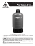
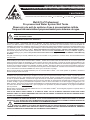
INSTALLATION, OPERATION & MAINTENANCE
INSTRUCTIONS D’INSTALLATION, D’OPÉRATION ET DE MAINTENANCE
INSTRUCTIONS INSTRUCCIONES DE INSTALACIÓN, OPERACIÓN
Y MANTENIMIENT
1400 Division Road, West Warwick, RI 02893
T: 401.884.6300
F: 401.885.2567
www.amtrol.com
Well-X-Trol® Professional
Pre-pressurized Water System Well Tanks
Réservoirs de puit de système d’eau à pressurisation initiale
Tanques hidroneumáticos prepresurizados para sistemas de agua
WARNING: REVIEW ALL GENERAL SAFETY AND PRODUCT INFORMATION PRIOR TO INSTALLATION.
AVERTISSEMENT : EXAMINER TOUTES LES INFORMATIONS CONCERNANT LA SÉCURITÉ ET LE PRODUIT
AVANT SON INSTALLATION.
ADVERTENCIA: ANTES DE INSTALARLO, REPASE LA INFORMACIÓN GENERAL DE SEGURIDAD Y L
INFORMACIÓN ACERCA DEL PRODUCTO.
Your WELL-X-TROL® Professional well tank by AMTROL® has been carefully assembled and factory tested. To enjoy the full
service your WELL-X-TROL® well tank can provide, you should read and follow all of the instructions in this manual. When all
installation steps have been completed, make sure you also follow the enclosed post-installation and start-up checklists before using
your AMTROL product. You should also read carefully the sections describing proper product maintenance, and follow the required
procedures as you use your WELL-X-TROL® . Return this booklet to its original envelope, and keep it with the WELL-X-TROL®.
This manual may become out-of-date by later amendments. Check our web site, www.amtrol.com, or ask your AMTROL supplier for
any updates relating to your product. This product comes with a limited seven (7) year warranty, see AMTROL Limited Warranty
for details.
Our goal is to ensure you are fully satisfied with your new well tank. If any questions or concerns arise, call Technical Service at
401-535-1216.
Ce réservoir de puits WELL-X-TROL® Professional d’Amtrol a été assemblé et testé à l’usine avec soin. Pour utiliser toute la
fonctionnalité que peut offrir le réservoir WELL-X-TROL® , veuillez lire et suivre toutes les instructions de ce manuel. Après avoir
effectué toutes les étapes de l’installation, il faut s’assurer de suivre aussi les listes ci-jointes de contrôle après installation et de
démarrage avant d’utiliser ce produit AMTROL. Lire aussi avec soin les sections décrivant la maintenance appropriée à ce produit
et suivre les procédures requises pour l’utilisation du WELL-X-TROL®. Remettre en place ce livret dans sa pochette d’origine et le
conserver avec le WELL-X-TROL®. Ce manuel peut être l’objet de révisions ultérieures. Consulter notre site Internet à www.amtrol.
com ou demander au fournisseur AMTROL les mises à jour concernant ce produit.
Notre but est d’assurer une entière satisfaction pour ce nouveau WELL-X-TROL® . Pour toute question ou problème, contacter le
Service technique au 401-535-1216.
Su tanque hidroneumático WELL-X-TROL® Professional fabricado por AMTROL ha sido cuidadosamente ensamblado y probado
en fábrica. Para que pueda disfrutar por completo el servicio que su tanque hidroneumático WELL-X-TROL® le puede proveer, le
recomendamos que lea y siga todas las instrucciones de este manual. Cuando complete todos los pasos de instalación, y antes
de usar su producto AMTROL, cerciórese de seguir las listas de verificación posinstalación y de puesta en marcha. Asimismo,
le recomendamos que lea cuidadosamente las secciones que describen el mantenimiento apropiado del producto y que, al usar
su WELL-X-TROL® , siga los procedimientos requeridos. Vuelva a colocar este folleto en su sobre original y téngalo junto a su
WELL-X-TROL®. Este manual puede quedar desactualizado por enmiendas posteriores, por lo que le recomendamos que verifique
en nuestro sitio de Web, www.amtrol.com, o que le pregunte a su proveedor de productos AMTROL, si hay alguna actualización
para su producto.
Nuestra meta es asegurar su completa satisfacción con su nuevo WELL-X-TROL® . Si tiene alguna pregunta o inquietud, llame al
Servicio Técnico al 401-535-1216.
THIS IS THE SAFETY ALERT SYMBOL. IT IS USED TO ALERT YOU TO POTENTIAL PERSONAL INJURY AND OTHER
HAZARDS. OBEY ALL SAFETY MESSAGES THAT FOLLOW THIS SYMBOL TO REDUCE THE RISK OF POSSIBLE INJURY
AS WELL AS PROPERTY DAMAGE.
VOICI LE SYMBOLE D’ALERTE DE SÉCURITÉ. IL EST UTILISÉ POUR SIGNALER LES RISQUES D’ACCIDENT OU AUTRES
DANGERS. IL FAUT RESPECTER TOUS LES MESSAGES DE SÉCURITÉ QUI SUIVENT CE SYMBOLE AFIN DE RÉDUIRE LES
RISQUES POTENTIELS DE BLESSURE OU DE DOMMAGE MATÉRIEL.
ESTE ES EL SÍMBOLO DE ALERTA DE SEGURIDAD. SE USA PARA ALERTARLE DE POSIBLES LESIONES Y
OTROS PELIGROS. PARA REDUCIR EL RIESGO LESIONES, ASÍ COMO DE DAÑOS MATERIALES, OBEDEZCA
TODOS LOS MENSAJES DE SEGURIDAD QUE ACOMPAÑAN A ESTE SÍMBOLO.
9015-868 (06/12)
MC#10185 (06/12)
1. GENERAL SAFETY INFORMATION
THIS TANK, LIKE MOST TANKS UNDER PRESSURE, WILL OVER TIME CORRODE OR FAIL AND/OR MAY BURST AND/OR LEAK
OR FLOOD (AND IN RARE CASES EXPLODE) WHICH CAN CAUSE SERIOUS OR FATAL PERSONAL INJURY AND PROPERTY
DAMAGE. TO MINIMIZE RISK, A LICENSED PROFESSIONAL MUST INSTALL AND PERIODICALLY INSPECT AND SERVICE THE UNIT. A DRIP PAN,
CONNECTED TO AN ADEQUATE DRAIN MUST BE INSTALLED IF LEAKING OR FLOODING CAN CAUSE PROPERTY DAMAGE.
READ CAREFULLY THE PRODUCT INSTALLATION, OPERATING AND MAINTENANCE MANUAL. FAILURE TO
FOLLOW THE INSTRUCTIONS AND WARNINGS IN THE MANUAL MAY RESULT IN SERIOUS OR FATAL INJURY
AND/OR PROPERTY DAMAGE, AND WILL VOID THE PRODUCT WARRANTY. THIS PRODUCT MUST BE INSTALLED BY A QUALIFIED
PROFESSIONAL. FOLLOW ALL APPLICABLE LOCAL AND STATE CODES AND REGULATIONS, IN THE ABSENCE OF SUCH CODES,
FOLLOW THE CURRENT EDITIONS OF THE NATIONAL PLUMBING CODE AND NATIONAL ELECTRIC CODE, AS APPLICABLE.
AS IN ALL PLUMBING PRODUCTS AND WATER STORAGE VESSELS, BACTERIA CAN GROW IN YOUR WELL-XTROL®, ESPECIALLY DURING TIMES OF NON-USE. CONSULT YOUR LOCAL PLUMBING OFFICIAL REGARDING
ANY STEPS YOU MAY WISH TO TAKE TO SAFELY DISINFECT YOUR HOME’S PLUMBING SYSTEM.
FOLLOW ALL OF THE INSTRUCTIONS AND RECOMMENDATIONS CONTAINED IN THIS MANUAL, AND THE
FOLLOWING ADDITIONAL SPECIFIC WARNINGS. FAILURE TO DO SO IS UNSAFE AND CAN CAUSE SERIOUS
EXPLOSION, SERIOUS OR FATAL PERSONAL INJURY AND PROPERTY DAMAGE.
EXPLOSION OR RUPTURE HAZARD. THE WELL-X-TROL MUST BE OPERATED SO THAT THE MAXIMUM SYSTEM
PRESSURE DOES NOT EXCEED 150 PSI OR LOCAL CODE REQUIREMENTS WHICHEVER IS LESS.
A RELIEF VALVE WITH A MAXIMUM RELIEF PRESSURE OF 125 PSI MUST BE INSTALLED IN THE SYSTEM. THE
RELIEF VALVE MUST BE CAPABLE OF DISCHARGING THE RATED CAPACITY OF THE PUMP AT THE MAXIMUM
SYSTEM PRESSURE.
FAILURE TO UTILIZE A PROPERLY SIZED WELL-X-TROL (BASED ON THE FOLLOWING SIZING INSTRUCTIONS)
WILL RESULT IN EXCESSIVE STRAIN ON THE PUMP AND MAY ULTIMATELY LEAD TO PRODUCT FAILURE,
LEAKING OR FLOODING AND PROPERTY DAMAGE.
DANGER! EXPLOSION HAZARD. IF YOU ADJUST THE PRE-CHARGE PRESSURE OR ADD PRESSURE TO A
TANK THAT IS CORRODED OR DAMAGED OR WITH DIMINISHED INTEGRITY THE TANK CAN BURST OR
EXPLODE, POSSIBLY CAUSING SERIOUS OR FATAL PERSONAL INJURY AND/OR PROPERTY DAMAGE.
• ONLY ADJUST THE PRE-CHARGE AS DESCRIBED IN THIS MANUAL WHEN THE TANK IS NEW OR WHEN THE
INTEGRITY OF THE TANK AND LACK OF INTERNAL OR EXTERNAL CORROSION IS CONFIRMED.
• ONLY QUALIFIED PROFESSIONALS SHOULD CHECK, ADJUST OR RE-CHARGE THE PRE-CHARGE OF TANKS.
DANGER! EXPLOSION HAZARD. WHEN THE WELL-X-TROL HAS BEEN IN SERVICE AND A CHANGE TO A
HIGHER PRE-CHARGE PRESSURE IS NECESSARY DUE TO A REQUIRED CHANGE IN THE PRESSURE SWITCH
SETTING, FAILURE TO FOLLOW INSTRUCTIONS BELOW CAN CAUSE A RUPTURE OR EXPLOSION, POSSIBLY CAUSING SERIOUS
OR FATAL PERSONAL INJURY, AND/OR PROPERTY DAMAGE. DO NOT ADJUST OR ADD PRESSURE IF THERE HAS BEEN A LOSS
OF AIR. DO NOT ADJUST THE PRE-CHARGE PRESSURE IF THERE IS VISIBLE EXTERIOR CORROSION. DO NOT ADJUST THE PRECHARGE PRESSURE IF THERE HAS BEEN A REDUCTION OF THE PUMP CYCLE TIME OR THE PRE-CHARGE PRESSURE COMPARED
TO ITS INITIAL SETTING. THIS IS BECAUSE REDUCTION IN PUMP CYCLE TIME CAN RESULT FROM LOSS OF TANK AIR PRESSURE
WHICH IN TURN CAN MEAN THERE MAY BE INTERNAL CORROSION AND ANY RE-PRESSURIZATION OR ADDITIONAL PRESSURE
COULD RESULT IN RUPTURE OR EXPLOSION.
CHLORINE & AGGRESSIVE WATER: THE WATER QUALITY CAN SIGNIFICANTLY INFLUENCE THE LIFE OF THIS
PRODUCT. YOU SHOULD TEST FOR CORROSIVE ELEMENTS, ACIDITY, TOTAL SOLIDS AND OTHER RELEVANT
CONTAMINANTS, INCLUDING CHLORINE AND TREAT YOUR WATER APPROPRIATELY TO INSURE SATISFACTORY PERFORMANCE
AND PREVENT PREMATURE FAILURE. FOR YOUR SAFETY, THE INFORMATION IN THIS MANUAL MUST BE FOLLOWED TO MINIMIZE
THE RISK OF ELECTRIC SHOCK, PROPERTY DAMAGE OR PERSONAL INJURY. PROPERLY GROUND TO CONFORM WITH ALL
GOVERNING CODES AND ORDINANCES.
INSTALL OR STORE WHERE TANK WILL NOT BE EXPOSED TO TEMPERATURES BELOW FREEZING OR ABOVE
100ºF. WATER FREEZING IN THE SYSTEM WILL BREAK IT. DO NOT ATTEMPT TO TREAT WATER OVER 100°F.
USE ONLY LEAD-FREE SOLDER AND FLUX FOR ALL SWEAT-SOLDER CONNECTIONS, AS REQUIRED BY
STATE AND FEDERAL CODES.
NOTE: INSPECT FOR SHIPPING DAMAGE AND NOTIFY FREIGHT CARRIER OR STORE WHERE PURCHASED IMMEDIATELY IF
DAMAGE IS PRESENT. TO AVOID RISK OF PERSONAL INJURY AND PROPERTY DAMAGE, IF THE PRODUCT APPEARS TO BE
MALFUNCTIONING OR SHOWS SIGNS OF CORROSION, CALL A QUALIFIED PROFESSIONAL IMMEDIATELY. CURRENT COPIES OF
THE PRODUCT MANUAL CAN BE VIEWED AT WWW.AMTROL.COM. USE PROPER SAFETY EQUIPMENT WHEN INSTALLING.
FAILURE TO FOLLOW THE ABOVE WARNINGS MAY RESULT IN SERIOUS OR FATAL PERSONAL INJURY OR DEATH
AND/OR PERSONAL PROPERTY DAMAGE, AND WILL VOID THE WARRANTY.
-2-
2. AMTROL INC. LIMITED PRODUCT WARRANTY
Products covered: all Products manufactured by AMTROL Inc. (“AMTROL”).
This warranty cannot be transferred – it is extended only to the original Purchaser or First User of the Product. By accepting and keeping
this Product you agree to all of the warranty terms and limitations of liability described below.
IMPORTANT WARNING – READ CAREFULLY THE INSTALLATION, OPERATING AND MAINTENANCE INSTRUCTIONS MANUAL
(“MANUAL”) to avoid serious personal injury and/or property damage and to ensure safe use and proper care of this product.
Who Receives AMTROL’s Product Warranty
All purchasers or first users of the new Product. The Warranty is non-transferable.
What is covered by this Warranty
AMTROL warrants to the purchaser or first user of the new Product that at the time of manufacture, the Product is free from defects in
material and workmanship. Any warranty claim must be made within one (1) year unless another time period is set forth in the Manual,
measured from the time the Product was purchased.
What AMTROL Will Do If You Have a Covered Warranty Claim
In the event of a breach of the foregoing warranty, AMTROL will at its option either make repairs to correct any defect in material or
workmanship or supply and ship either new or used replacement parts or products. AMTROL will not accept any claims for labor or other
costs.
What This Warranty Does Not Cover — Exclusions and Limitations
This Warranty does not cover any failure or problem unless it was caused by a defect in material or workmanship. In addition, this Warranty
shall not apply:
• if the Product is not correctly installed, operated, repaired or maintained as described in the Manual provided with the Product;
• to any failure or malfunction resulting from abuse (including freezing); improper or negligent: handling, shipping (by anyone other than
AMTROL), storage, use, operation, accident; or alteration, lightning, flood or any other environmental condition;
• to any failure or problem resulting from the use of the Product for any purpose other than those specified in the accompanying Manual or
alteration of any part of the product;
• if the Product is used anywhere except the United States, its territories or possessions, or Canada;
• this Warranty does not cover labor costs, shipping charges, service charges, delivery expenses, administrative fees or any costs incurred
in removing or reinstalling the Product;
• this Warranty does not cover any claims submitted to AMTROL or an AMTROL-authorized distributor or retailer more than 30 days after
expiration of the applicable warranty time period described in this Warranty;
• this Warranty also does not cover repair or replacement costs not authorized in advance by AMTROL.
Additional Warranty Limitations
ALL IMPLIED WARRANTIES, INCLUDING THE IMPLIED WARRANTIES OF MERCHANTABILITY AND FITNESS FOR A PARTICULAR
PURPOSE ARE SPECIFICALLY DISCLAIMED.
Limitations of Remedies
THE REMEDIES CONTAINED IN THIS WARRANTY ARE THE PURCHASER’S OR FIRST USER’S EXCLUSIVE REMEDIES. IN NO
CIRCUMSTANCES WILL AMTROL BE LIABLE FOR MORE THAN, AND PURCHASER-FIRST USER’S REMEDIES SHALL NOT
EXCEED, THE PRICE PAID FOR THE PRODUCT. IN NO CASE SHALL AMTROL BE LIABLE FOR ANY SPECIAL, INDIRECT,
INCIDENTAL OR CONSEQUENTIAL DAMAGES, WHETHER RESULTING FROM NONDELIVERY OR FROM THE USE, MISUSE, OR
INABILITY TO USE THE PRODUCT OR FROM DEFECTS IN THE PRODUCT OR FROM AMTROL’S OWN NEGLIGENCE OR OTHER
TORT. This exclusion applies regardless of whether such damages are sought for breach of warranty, breach of contract, negligence, strict
liability, in tort or under any other legal theory. Such damages include, but are not limited to, inconvenience, loss or damage to property,
mold, loss of profits, loss of savings or revenue, loss of use of the Products or any associated equipment, facilities, buildings or services,
downtime, and the claims of third parties including customers.
What To Do If You Have a Problem Covered By This Warranty
Any covered Warranty service must be authorized by AMTROL. Contact the person from whom you purchased the Product, who must receive
authorization from an AMTROL distributor or AMTROL. If you do not receive a prompt response, call AMTROL directly at 877-517-9673.
Notice of a Warranty claim should be submitted by the authorized distributor to AMTROL at the following address:
AMTROL Inc.
Warranty Claim Dept.
1400 Division Rd.
West Warwick, RI 02893
Before AMTROL determines to provide any replacement part or Product, it may as a pre-condition to making such a determination require
that the warranty claimant ship the Product, postage prepaid to an authorized AMTROL distributor, or to AMTROL and provide proof of
purchase evidenced by the original sales receipt or Product registration.
Replacement Product Warranty
In case of replacement of a Product or any component part, AMTROL reserves the right to make changes in the design, construction, or
material of the substitute components or products, which shall be subject to all of the terms and limitations of this Warranty, except that the
applicable warranty periods shall be reduced by the amount of time the warranty claimant owned the product prior to submitting notification
of the warranty claim.
AMTROL Inc. • 1400 Division Road • W. Warwick, Rhode Island 02893 • Telephone 401-884-6300 • Fax 401-885-2567
Revised 7/03
The AMTROL logo, AMTROL, Well-X-Trol, Champion, Wel-Flo, Ex-trol, Fill-Trol, Therm-X-Trol, and Boilermate are registered trademarks of AMTROL Inc. and its affiliates in the U.S. and
elswhere. All rights reserved.
-3-
3. PRE-INSTALLATION CHECKLIST
IMPORTANT STEPS AND DECISIONS REQUIRED BEFORE INSTALLATION
THIS PRODUCT MUST BE INSTALLED AND
❑
MAINTAINED BY A LICENSED PROFESSIONAL. IN
RIP PAN AND DRAIN: To avoid leaking and/or property
❑Ddamage,
install with a drip pan connected to an adequate
ADDITION TO THE INSTRUCTIONS IN THIS MANUAL,
FOLLOW ALL APPLICABLE LOCAL AND STATE
CODES OR IN THE ABSENCE OF SUCH CODES, THE
CURRENT EDITIONS OF THE NATIONAL PLUMBING
CODE AND THE NATIONAL ELECTRIC CODE.
working drain kept clear at all times.
MAXIMUM WORKING PRESSURES
RELIEF VALVE REQUIRED
Every WELL-X-TROL is air tested to 150
psig, the maximum working pressure for the WELL-X-TROL line.
A relief valve should be installed which is
set to open at excessive pressures (125 psig). This will protect
the WELL-X-TROL and other system components should the
pressure switch malfunction and fail to shut the pump off.
The relief valve should be installed at the connection of the
WELL-X-TROL to the system piping and have a discharge equal
to the pump’s capacity at 125 psig.
Should pressures exceed 150 psig, proper selection and sizing of
an A.S.M.E. constructed WELL-X-TROL should be made.
4. HOW YOUR WELL-X-TROL WORKS
OPERATING CHARACTERISTICS
The WELL-X-TROL principle employs a mechanical sealed-in
heavy duty diaphragm to allow an air cushion to be pre-pressurized
before leaving the factory.
NOTE: This is an example. Not all precharge pressure is 38 psi.
Not all system pressures shut pump off at 60 psi
Water is contained in a separate molded rigid polypropylene
liner that is supported by the outside steel shell and covered by
a diaphragm. This provides a completely non-corrosive water
reservoir, eliminating any contact of system water with ferrous
metal. The WELL-X-TROL is shipped with its total volume filled
with air pressured to a standard precharge. As water enters
the WELL-X-TROL, the diaphragm is flexed, compressing the
air cushion, reducing its volume by the same volume of water
that enters. As the volume of air decreases, the pressure in the
WELL-X-TROL increases, so that it always equals the pressure
exerted by the water. Since air pressure and water pressure are
always equal, the diaphragm is never under any strain. It merely
flexes or floats between the water and air. When properly sized,
the air cushion in the WELL-X-TROL will be of sufficient volume
at minimum pressure (pump cut-in) to allow a desired volume of
water to enter the WELL-X-TROL with the subsequent pressure
increase within the specified operating pressure range as set by
the pressure switch.
60 PSIG
38 PSIG
38
A
60
55 PSIG
55
B
C
A. Factory installed precharged air cushion. Pump off.
B. When pump starts, water enters the reservoir. At 60 psig, system
is filled. Pump shuts off.
C. When water is demanded, pressure in the air chamber forces
water into the system. Pump stays off.
-4-
5. INSTALLATION INSTRUCTIONS
System Connection
Explosion Hazard. Failure to follow
these instructions can cause a
rupture or explosion possibly causing serious or fatal
injury, flooding, and / or property damage.
In-line Models WX-101, 102, 103, 105 and 200
In-line models WX-101, 102, 103 are conventionally installed
directly in the main water supply line with a 3/4" connection. For
model WX-200, a 1" fitting is used.
System Connection
1. Locate the WELL-X-TROL in the final desired location.
Vertical Stand Models WX-201 through WX-350
Vertical stand models WX-201 through WX-302 are equipped with
an elbow system connection. The WX-201, WX-202, WX-202XL
and the WX-203 have a 1" elbow. The WX-205, WX-250, WX-251,
WX-255, WX-252, WX-302 and WX-350 have a 1 1/4" elbow.
2. Level as necessary.
3. To eliminate friction loss, do not reduce the pipe size from
the pump to the WELL-X-TROL.
Start Up
Location
Fine Tuning Procedures
Many times the actual pressure switch will vary from the
standard pressure range indicated. These variations could cause
a momentary lag of water delivery, as the pressure switch is not
“tuned to the WELL-X-TROL precharge pressure”.
1. Fill the system and WELL-X-TROL until pump cuts off.
2. Open one or more fixtures to drain the WELL-X-TROL.
3. If there is a momentary pause in the water flow from
the time the WELL-X-TROL is emptied and the pump
starts, adjust pump cut-in setting clockwise slightly (see
figure 2).
4. Close fixtures and refill WELL-X-TROL to pump cut off.
Check time to fill.
5. Open fixtures and see if pause in water is eliminated. If not,
continue adjusting pressure switch.
Proper WELL-X-TROL Location
The WELL-X-TROL should be installed as close as possible to
the pressure switch. This will reduce the adverse effects of added
friction loss and pressure switch bouncing, and the difference in
elevation between WELL-X-TROL and switch.
DANGER! EXPLOSION HAZARD.
WHEN THE WELL-X-TROL HAS BEEN
IN SERVICE AND A CHANGE TO A HIGHER PRE-CHARGE
PRESSURE IS NECESSARY DUE TO A REQUIRED CHANGE
IN THE PRESSURE SWITCH SETTING, FAILURE TO
FOLLOW INSTRUCTIONS BELOW CAN CAUSE A RUPTURE
OR EXPLOSION, POSSIBLY CAUSING SERIOUS OR FATAL
PERSONAL INJURY, AND/OR PROPERTY DAMAGE.
• DO NOT ADJUST OR ADD PRESSURE IF THERE HAS
BEEN A LOSS OF AIR.
• DO NOT ADJUST THE PRE-CHARGE PRESSURE IF
THERE IS VISIBLE EXTERIOR CORROSION.
• DO NOT ADJUST THE PRE-CHARGE PRESSURE IF THERE
HAS BEEN A REDUCTION OF THE PUMP CYCLE TIME
OR THE PRE-CHARGE PRESSURE COMPARED TO ITS
INITIAL SETTING. THIS IS BECAUSE REDUCTION IN PUMP
CYCLE TIME CAN RESULT FROM LOSS OF TANK AIR
PRESSURE WHICH IN TURN CAN MEAN THERE MAY BE
INTERNAL CORROSION AND ANY RE-PRESSURIZATION
OR ADDITIONAL PRESSURE COULD RESULT IN
RUPTURE OR EXPLOSION.
FIGURE 2
Pressure Adjustment Clockwise
To Increase Cut-Out Pressure
Counter Clockwise To
Decrease Cut-Out Pressure
Adjusting Precharge After Installation
Adjusting Precharge
Step 1. Drain tank of all water. Check precharge pressure in the
WELL-X-TROL Tank.
Step 2. Release or add air as necessary to make the recharge
pressure 2 psig below the pressure switch pump cut-in setting.
All WELL-X-TROL “Underground Tanks” are designed for
direct burial and must be installed in the vertical position only.
To eliminate danger of freezing, tank should be buried below the
frost line.
The following steps should be taken when installing a
WELL-X-TROL “Underground Tanks”:
1. Make sure that the tank will be buried below the frost line and
above the water table.
2. Remove plastic bag and check tank precharge. Factory
precharge is 38 psig. Replace air stem cap securely. Follow
adjusting precharge procedure.
3. Important: Install tank on firm rock-free earth.
4. The Water lines from the pump to the tank and switch location
should be the same size to prevent switch cycling.
5. Check the system for performance and inspect for leaks.
6. Important: Backfill hole with sand. Firmly tamp fill to prevent
settling. Failure to do so will shorten tank life.
7. Fill out pressure tank location sticker and affix to power panel or
other visible surface so tank can be easily located at a later time
Prior to Installation
Step 1. Remove protective air valve cap
Step 2. Check precharge pressure (pressure should be + or 10% of the factory setting)
Step 3. Release or add air as necessary to make the precharge
pressure 2 psig below the pressure
switch pump cut-in setting. (Example,
AIR VALVE
if you have a WX-202XL with a
LABEL
precharge of 38 psig, and you have a
pressure switch setting of 30/50 psig,
adjust precharge of your WX-202XL
from 38 psig to 28 psig.)
AIR
Step 4. Replace protective air valve cap. Peel
VALVE
off backing of label and apply over air
CAP
valve cap.
AIR VALVE LABEL
IN POSITION
OVER CAP
FIGURE 1
-5-
6. UNDERGROUND INSTALLATION
INSTALLATION SOUTERRAINE
INSTALACIÓN BAJO TIERRA
RELIEF VALVE
SOUPAPE DE DÉTENTE
VÁLVULA DE ALIVIO
POSSIBLE PRESSURE
SWITCH LOCATION
EMPLACEMENT POSSIBLE
DU PRESSOSTAT
POSIBLE UBICACIÓN DEL
INTERRUPTOR DE PRESIÓN
PRESSURE TANK LOCATION
STICKER SUPPLIED WITH
EACH UNIT
AUTOCOLLANT D’EMPLACEMENT
DU RÉSERVOIR PRESSURISÉ
FOURNI AVEC CHAQUE APPAREIL
ETIQUETA DE UBICACIÓN DEL
TANQUE DE PRESIÓN PROVISTO
CON CADA UNIDAD
WELL
PUIT
POZO N
W
(O)
BUILDING FOUNDATION
FONDATION DU BÂTIMENT
CIMIENTOS DEL EDIFICIO
E
110
S
PRESSURE TANK LOCATION,
FOR EXAMPLE
EXEMPLE D’EMPLACEMENT
DE RÉSERVOIR PRESSURISÉ
UBICACIÓN DEL TANQUE DE
PRESIÓN. EJEMPLO
FROST LINE
PROFONDEUR LIMITE DE GEL
NIVEL DE CONGELAMIENTO
WELL-X-TROL
"UG"
TO HOUSE
VERS LA MAISON
A LA CASA
ROCK FREE
COARSE SAND
GROS SABLE
SANS PIERRE
ARENA GRUESA
SIN ROCAS
PUMP
POMPE
BOMBA
7. MANIFOLD INSTALLATIONS
INSTALLATIONS À RAMPE DE DISTRIBUTION
INSTALACIÓN DE COLECTORES
-14-
8. RECOMMENDED INSTALLATIONS
INSTALLATIONS RECOMMANDÉES
INSTALACIONES RECOMENDADAS
WX-100 Series WELL-X-TROL with tank mounted at jet pump.
WELL-X-TROL série WX-100 avec réservoir monté sur pompe à jet.
WELL-X-TROL serie WX-100, con tanque montado en la bomba de
chorro.
WX-103 or WX-200 with pump stand. WX-200 with pump stand
mounting jet pump.
WX-103 ou WX-200 avec le support de pompe. WX-200 avec le
support de pompe et le montage de pompe à jet.
WX-103 o WX-200 con base para bomba. WX-200 con base para
bomba a chorro.
WX-201 through WX-350 WELL-X-TROL installed on-line with jet
pump.
WELL-X-TROL WX-201 à WX-350, installé en ligne avec la pompe
à jet.
WELL-X-TROL WX-201 a WX-350 instalado en línea con una bomba
de chorro
WX-201 through WX-350 WELL-X-TROL installed on-line using
submersible pump.
WELL-X-TROL WX-201 à WX-350, installé en ligne avec pompe
submersible.
WELL-X-TROL WX-201 a WX-350, instalado en lÌnea usando una
bomba sumergible.
WX-201 through WX-350 WELL-X-TROL use pump stand.
WELL-X-TROL WX-201 à WX-350 utilisant le support de pompe.
WELL-X-TROL WX-201 a WX-350, usando base para bomba.
-15-
SERVICE RECORD
REGISTRE D’ENTRETIEN
REGISTRO DE SERVICIO
DATE
DATE
FECHA
SERVICE PERFORMED
ENTRETIEN EFFECTUÉ
SERVICIO REALIZADO COMMENTS
COMMENTAIRES
COMENTARIOS
CONTRACTOR
ENTREPRENEUR
CONTRATISTA
Model Number / Numéro de modèle / Modelo
GPM Flow from Well / Débit (gallons/minute) du puits / Flujo del pozo en GPM
Pump cut in / Activation de la pompe / Arranque de la bomba
Pump cut out / Arrêt de la pompe / Parada de la bomba
Tank pre-charge / Charge initiale du réservoir / Precarga del tanque
1400 Division Road, West Warwick, RI 02893
9015-868 (06/12)
T: 401.884.6300
F: 401.885.2567
www.amtrol.com
MC#10185 (06/12)