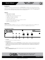
1
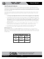
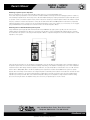
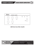
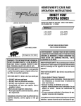
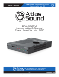
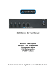
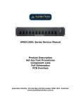
MA40G / MA60G
Mixer Amplifier
Owner’s Manual
MA40G
Front Silkscreen
Artwork
MA40G
& MA60G
Mixer Amplifiers
MA60G Front Silkscreen Artwork
Power
Limit
Input 2
Input 2
Input 3
Level
Level
Level
Signal
1601 Jack McKay Blvd
Ennis, TX 75119
800.876.3333
Input 3
Input 2 Mute
Input 3 Mute
L
Input 1
Balanced Input
Input 1
Phantom Power
Input 1
On
On
On
Mic
Off
Off
Off
Line
AtlasSound.com
Remote
Mute
Power
R
0
Limit
Signal
40 Watts
70.7V/100V
Out
InputSpeaker
2
Input 1
VOX
Sense
Unbalanced
Level
Input 2
L
R
Input 3 Mute
Phantom Power
Input 1
On
On
On
Mic
Level
1601 Jack McKay Blvd
Ennis, TX 75119
800.876.3333
Off
Off
Off
Line
0
100V -240V ~ 50Hz/60Hz 750mA
Level
Input 3
Input 2 Mute
Input 1
Balanced Input
Input 3
10
AtlasSound.com
Remote
Mute
60 Watts
70.7V/100V
Speaker Out
10
VOX
Sense
Unbalanced
100V -240V ~ 50Hz/60Hz 1A
1601 Jack McKay Blvd. • Ennis, Texas 75119 U.S.A.
Telephone: 800.876.3333 • Fax: 800.765.3435
– 1 –
Specifications are subject to change without notice.
AtlasSound.com
MA40G / MA60G
Mixer Amplifier
Owner’s Manual
Table of Contents
Important Safety Instructions................................................................................................... 3
Introduction............................................................................................................................... 5
Features.................................................................................................................................... 5
Applications............................................................................................................................... 5
Front Panel Description............................................................................................................. 5
Rear Panel Description.............................................................................................................. 6
Wiring the MA40G / MA60G.................................................................................................... 7
Optional Level Control Security Cover...................................................................................... 7
Optional Rack Mount Kit........................................................................................................... 7
Limit LED & Load Considerations............................................................................................. 8
Specifications............................................................................................................................ 10
Warranty.................................................................................................................................... 12
1601 Jack McKay Blvd. • Ennis, Texas 75119 U.S.A.
Telephone: 800.876.3333 • Fax: 800.765.3435
AtlasSound.com
– 2 –
Specifications are subject to change without notice.
MA40G / MA60G
Mixer Amplifier
Owner’s Manual
Important Safety Instructions
The lightning flash with arrowhead symbol within an
equilateral triangle, is intended to alert the user to the
presence of uninsulated “dangerous voltage “ within the
product’s enclosure that may be of sufficient magnitude
to constitute a risk of electric shock to persons.
CAUTION
ier
A35
d 35W
ngineered
ound
HINA
RISK OF ELECTRIC SHOCK
DO NOT OPEN
ATTENTION
´
RISQUE DE DECHARGE ELECTRIQUE
-NE PAS OUVRIR.
The exclamation point within an equilateral triangle is
intended to alert the user to the presence of important
operating and maintenance (servicing) instructions in the
literature accompanying the product.
TO REDUCE THE RISK OF FIRE OR ELECTRIC SHOCK
DO NOT EXPOSE THIS APPLIANCE TO RAIN OR MOISTURE.
CAUTION – When Installing the Product
WARNING
1. Read these instructions.
2. Keep these instructions.
3. Heed all warnings.
4. Follow all instructions.
5. Do not use this device near water.
6. Clean only with dry cloth.
7. Do not block any ventilation openings. Install in accordance with the manufacturer’s instructions.
8. Do not install near any heat sources such as radiators, heat registers, stoves, or other device (including amplifiers) that produce heat.
9. Do not defeat the safety purpose of the polarized or grounding-type plug. A polarized plug has two blades with one wider than the other. A grounding type plug has two blades and a third
grounding prong. The wide blade or the third prong are provided for your safety. If the provided plug does not fit into your outlet, consult an electrician for replacement of the obsolete outlet.
10.Protect the power cord from being walked on or pinched particularly at plugs, convenience receptacles, and the point where they exit from the device.
11.Only use attachments/accessories specified by the manufacturer.
12.Use only with the cart, stand, tripod, bracket, or table specified by the manufacturer, or sold with the device. When a cart is used use caution when moving the cart/device combination to avoid injury from tip-over.
13.Unplug this device during lightning storms or when unused for long periods of time.
14.Refer all servicing to qualified service personnel. Servicing is required when the device has been
damaged in any way, such as power-supply cord or plug is damaged, liquid has been spilled, or objects have fallen into the device, the device has been exposed to rain or moisture, does not operate normally, or has been dropped.
15.WARNING: To reduce the risk of fire or electric shock, this device should not be exposed to rain or
moisture and objects filled with liquids, such as a vase, should not be placed on this device.
16.To completely disconnect this equipment from the mains, disconnect the power supply cord plug from the receptacle.
17.The mains plug of the power supply cord shall remain readily operable.
1.
2.
3.
4.
5.
Plugging in or unplugging the power cord with wet hands may result in electric shock.
Never move the device with the power cord plugged into the wall, as damage to the power cord may result.
When unplugging the cord from the wall, grasp the plug, NOT the cord.
Never install this device in humid or dusty locations, nor in direct sunlight, near sources of heat, or in areas where sooty smoke or steam are present. Fire and electric shock may result.
Keep all sides of the device at least 31⁄2" away from objects that may obstruct air flow to prevent the unit's internal temperature rise.
1601 Jack McKay Blvd. • Ennis, Texas 75119 U.S.A.
Telephone: 800.876.3333 • Fax: 800.765.3435
– 3 –
Specifications are subject to change without notice.
AtlasSound.com
MA40G / MA60G
Mixer Amplifier
Owner’s Manual
WARNING – When the Device is in Use
1. To prevent electric shock, do not remove the device cover as there are high voltage components inside. Refer all servicing to Atlas Sound.
2. Should any of the following irregularities occur during use, immediately switch off the power,
disconnect the power cord from the AC outlet and contact Atlas Sound. Do not to attempt to continue operation with the device as this may cause fire or electric shock:
• Smoke or strange smell coming from the unit.
• If the device falls or the case is damaged.
• If water or any metallic objects falls into the device.
• If the power supply cord is damaged in any way.
• If the device is malfunctioning.
3. Do not insert or drop metallic objects or flammable materials into the ventilation holes of the device's cover, as this may result in electric shock or fire.
4. Do not place any containers with liquid or metallic objects on the top of the device. If any liquid spills into the unit, fire or electric shock may result.
5. Never operate this device or touch the power supply cord during an electrical storm, electric shock
may result.
6. Never exceed the wattage on the product when connecting equipment. Fire and/or property damage
may result.
7. Operate the device only with the voltage specified on the unit. Fire and/or electric shock may result if a higher voltage is used.
8. Do not modify, kink, or cut the power cord. Do not place the power cord in close proximity to heaters and do not place heavy objects on the power cord, including the device itself, doing so may result in fire or electrical shock.
9. Ensure that the safety ground terminal is connected to a proper ground. Never connect the ground to a gas pipe as a catastrophic disaster may result.
10.Be sure the installation of the product is stable, avoid slanted surfaces as the product may fall and cause injury or property damage.
CAUTION – When the Device is in Use
1. Never place heavy objects on the product, causing it to fall and/or break, resulting in personal injury and
property damage. In addition, the product itself may fall and cause injury and property damage.
2. Contact Atlas Sound for instructions on cleaning the inside of the unit. Large accumulations of dust
inside the unit may result in heat buildup and fire.
3. Ensure that the power supply plug is securely plugged into the wall outlet. Never allow dust to
accumulate on the power plug or inside the wall outlet.
4. When cleaning the unit or the unit is not to be operated for an extended time period, unplug the power
cord from the wall.
1601 Jack McKay Blvd. • Ennis, Texas 75119 U.S.A.
Telephone: 800.876.3333 • Fax: 800.765.3435
AtlasSound.com
– 4 –
Specifications are subject to change without notice.
MA40G / MA60G
Mixer Amplifier
Owner’s Manual
Introduction
Congratulations and thank you for purchasing the Atlas Sound MA40G/MA60G mixer amplifier. This new and innovative professional
grade product has been designed from the ground up to include the important features that professional installation personnel require to
meet or exceed their customer’s expectations. Small and compact, and engineered for reliability, the Atlas Sound MA40G/MA60G will
provide years of service and flexibility in today’s background music and paging applications.
Features
• MA40G - 40W into 70.7V/100V
• MA60G - 60W into 70.7V/100V
• One Balanced Mic / Line / Tel Input w/ Phantom Power
• 2 Unbalanced, Summing Line Level Inputs
• Variable Mute Sensitivity Control for Input 1
• Contact Closure Mute Terminals
• Rear Mounted Dip Switch Allows Mute Receive for Inputs Two and Three
• Global Power Supply, 100VAC-240VAC ~ 50/60Hz
• Optional Level Control Security Cover
MA40G Front Silkscreen Artwork
Applications
The Atlas Sound MA40G and MA60G are the perfect choice for distributed business paging and background music (BGM) systems,
small to medium speech privacy systems and in applications where music on hold (MOH) plus paging is required.
Front Panel Description
Power
Limit
1
2
2. Limit
L
Input 2
Input 3
Level
Level
Level
4
5
6
Signal
3
1. Power LED
Input 2
Input 3
This LED illuminates when the AC Mains are plugged in.
Input 2 Mute
Input 1
Input
LEDBalanced
Indicator
Input 1
Input 3 Mute
Phantom Power
Input 1
On
On
On
Mic
Off
Off
Off
Line
1601 Jack McKay Blvd
Ennis, TX 75119
800.876.3333
AtlasSound.com
Remote
Mute
40 Watts
70.7V/100V
Speaker Out
The LIMIT LED will illuminate when the MA40G/MA60G is in a clipping
condition, caused by excessively high input levels 0
10
or a GAIN control is turned up R
too high. An occasional flash is OK.VOX
Check that the proper signal level is being fed into the Sense
inputs and/or turn the input gain down until the LED is no longer illuminated. Refer to Limit LED & Load Conditions for Unbalanced
100V -240V ~ 50Hz/60Hz 750mA
more information.
3. Signal LED
When the signal LED illuminates, this indicates that input signals connected to the amplifier are capable of
driving the MA40G/MA60G to full power.
1601 Jack McKay Blvd. • Ennis, Texas 75119 U.S.A.
Telephone: 800.876.3333 • Fax: 800.765.3435
– 5 –
Specifications are subject to change without notice.
AtlasSound.com
MA40G / MA60G
Mixer Amplifier
Owner’s Manual
4. Input 1 Gain
Input 1 level control potentiometer varies the amplitude of the signal fed into the amplifier. Turn clockwise to increase and
counter-clockwise to decrease the signal level.
5. Input 2 Gain
Input 2 level control potentiometer varies the amplitude of the signal fed into the amplifier. Turn clockwise to increase and
counter-clockwise to decrease the signal level.
Input 1
Input 2
Input 3
6. Input 3 Gain
Power
Limit the amplitude
Signal
Input 3 level control potentiometet
varies
of the signal fed into the amplifier. Turn clockwise to increase and
counter-clockwise to decrease the signal level.
Level
Level
Level
Rear Panel Description
Input 2
Input 2 Mute
Input 3 Mute
L
Input 1
Balanced Input
1601 Jack McKay Blvd
Ennis, TX 75119
800.876.3333
Input 3
Phantom Power
Input 1
On
On
On
Mic
Off
Off
Off
Line
AtlasSound.com
0
R
40 Watts
70.7V/100V
Speaker Out
Remote
Mute
10
VOX
Sense
Unbalanced
2
3
100V -240V ~ 50Hz/60Hz 750mA
4
5
1
8
7
6
1. Multi Function Dipswitch
Understanding the functionality of the dipswitches is key to maximizing the versatility of the MA40G or MA60G.
ON
OFF
Input 2 Mute
Input 3 Mute
Phantom Power
Input 1
On
On
On
Mic
Off
Off
Off
Line
SWITCH 1 - Input 2 Mute - When "ON", Input 2 signals will be muted if a signal is present on Input 1 (Refer to VOX Sensitivity Control), or if a contact closure is present on the remote mute terminals.
SWITCH 2 - Input 3 Mute - When "ON", Input 3 signals will be muted upon a signal present on Input 1 (Refer to VOX Sensitivity Control), or if a contact closure is present on the remote mute terminals.
SWITCH 3 - Phantom Power - When "ON", applies Phantom Power 24VDC to Input 1 terminals for condenser type microphones. Note: Only use this feature if you are using condenser microphones, otherwise leave in the "OFF" position.
SWITCH 4 - Input 1 - When in the "MIC" position, Input 1 will accept microphone level signals; when in the "Line/Tel" position,
Input 1 will accept line level or telephone signals.
2. Input 1
Balanced mic or line level signals connect to the (+), (–), and (G) terminals. Refer to the chart on this page for the following setting. Switch 4, labeled Input 1, must be set to the proper position for mic or line level. If you are connecting an unbalanced line level input, tie (short) the (G) and (–) terminals together. If transformer isolation is required for Input 1, contact Atlas Sound for details.
3. Input 2
Input 2 consists of stereo summing inputs, suitable for connection to the output of CD/DVD players, etc.
1601 Jack McKay Blvd. • Ennis, Texas 75119 U.S.A.
Telephone: 800.876.3333 • Fax: 800.765.3435
AtlasSound.com
– 6 –
Specifications are subject to change without notice.
MA40G / MA60G
Mixer Amplifier
Owner’s Manual
4.
Input 3
Input 3 consists of stereo summing inputs, suitable for connection to the output of CD/DVD players, etc.
5. 6.
7.
8.
Mute Sensitivity Control
VOX Mute Sensitivity Control adjusts how sensitive the mute send circuitry on Input 1 reacts. Setting the control fully counter-
clockwise will lower the sensitivity, where a higher amplitude signal will be required at Input 1 to trigger the mute send circuits. Fully clockwise will raise the sensitivity of the mute circuits, where a lower amplitude signal will trigger a mute send. Careful
calibration of this control may be required to fully utilize the capabilities of the mute circuits.
70.7V / 100V Speaker Connections
For loudspeaker connections, follow the labeling paying special attention to the polarity or proceed to the Limit LED & Load
Considerations section. Note: Do not short the terminals together or damage may occur.
Global IEC AC Mains Power Receptacle
The MA Models support global power sources from 100V - 240V 50/60Hz. The package contains a cord that has an international IEC connector to a 120V USA type plug. It may be necessary to replace the removable power cord to meet your AC mains plug type used in your country. Note: It is not required to change the fuse for the different AC mains voltages.
Remote Mute Connector
Shorting the Remote Mute terminals will mute inputs 2 and/or 3, depending on how their dipswitch settings are set for switch positions 1 and 2 labeled "Mute Rec"/"Input 2" & "Input 3". In the "ON" position, the corresponding channel will be muted when the terminals are shorted together. This connection is usually done via remote switch on a microphone.
Wiring the MA40G/MA60G
Speaker Outputs - Use 2 conductor unshielded wire of the appropriate gauge. If you are unsure about this, contact Atlas Sound Tech
Support at 1-800-876-3333. Make sure you know how many speakers you need and what tap value you intend to use.
Mic/Line Input - 2 conductor with shield for low level signals of 20 - 22-gauge is best. Maintain the proper polarity, + to +, – to – , and
shield to ground.
Unbalanced Inputs and Outputs - Pre-made RCA cables can be purchased from vendors to simplify interconnection to external devices.
Security Cover Option
In order to prevent unauthorized operation of the MA40G & MA60G, optional security covers are available which take the place of the
front panel knobs. After the MA amplifier has been installed and is operating as desired, grasp the front panel knobs and pull straight out
from the front panel. Replace the knobs with security covers, Atlas Sound part number MPVCC-5, available in quantities of 5.
or
Front Panel Knob
Security Cover
Rack Mount Kit Option
The MA40G & MA60G can be rack mounted as a single unit or with two units together. To do so a PA702RMK Rack Mount Kit needs to
be purchased from Atlas Sound.
1601 Jack McKay Blvd. • Ennis, Texas 75119 U.S.A.
Telephone: 800.876.3333 • Fax: 800.765.3435
– 7 –
Specifications are subject to change without notice.
AtlasSound.com
MA40G / MA60G
Mixer Amplifier
Owner’s Manual
Limit LED and Load Consideration
If the Red Limit LED illuminates, the amplifier has sensed an improper load or the input signal is too high, triggering the protection
circuitry. When the load sense Limit circuitry is engaged the amp will operate but at a lower power output. It is s highly recommended
to discontinue use immediately and correct the fault condition. If you continue to operate with the RED Limit LED on, the second stage
of the current sense circuit may engage causing the amp not to pass any signal. To reset the amp turn down the Level controls and turn
the power off for 10 seconds.
In most situations when the Limit LED is in the illuminated steady state it means the speaker system load to the amp is lower than
what the amp is rated. This usually is detected when the system is first set up. Below are a few load conditions to check for if the
Limit LED is on.
1.
Connected to the wrong speaker terminal. Always check the speaker terminal to the type of load you are using. Example: If you are installing a 70V or 100V system make sure the wires are connected to the 70V/100V and common (COM) terminals.
2. Too many speakers connected to the amp. This is a very common mistake. If you are using a 60W amp and using the 70V speaker terminals, add up the number of speakers and their wattage selections at the speaker. If they exceed 60W you must retap the speakers or remove the correct amount of speaker wattage until the wattage is 60W or less. Example if you are using a 30W tap you can only connect 2 speakers to the amp. If you are using the 7.5W tap, you can connect 8 speakers. If you have too many speakers on the amp it will load the amp down, causing excessive current demand and will trigger the Limit & Protect circuit.
3. Wrong speaker tap selection. It is also common in a 70V or 100V system that one of the speakers is set at too low of an impedance (8ohm) and not a 70v or 100v tap. Note: It only takes one speaker to load the amp down incorrectly.
4. Short in system. This is common if the wire is run in metal conduit and the wire got nicked during the wire pull.
5. Speaker Level Controls. If an L-PAD or stepped attenuator is wired wrong it can also load a system down.
Measuring Speaker Loads
Below is an Impedance load chart for the MA40G and MA60G. Measure the load impedance prior to connecting the load to the
amplifier. The enclosed load chart will provide the information to determine if the load or speaker system impedance is too low for the
amplifier's rating. In every install it is always recommended to measure the load prior to turning the system on to be sure the system
is installed correctly.
MA40G & MA60G Max Load Chart
Speaker
Selection
MA40G
MA60G
70.7V
125 Ohms
83 Ohms
100V
250 Ohms
166 Ohms
1601 Jack McKay Blvd. • Ennis, Texas 75119 U.S.A.
Telephone: 800.876.3333 • Fax: 800.765.3435
AtlasSound.com
– 8 –
Specifications are subject to change without notice.
MA40G / MA60G
Mixer Amplifier
Owner’s Manual
Measuring a Speaker System's Impedance
Note: It is important to only use an Audio Impedance Meter and not a conventional Volt/Ohm meter.
A true audio frequency impedance meter is essential for reliable installation of background music and paging systems in residences,
office buildings and public areas. Avoid costly service calls and amplifier damage by verifying actual speaker system impedance prior
to operation. Unlike conventional volt/ohm meters, which measure DC resistance, an Audio Impedance Meter unit utilizes an internal
frequency oscillator to measure true impedance. It may also be utilized with 70.7V and 100V speaker line transformers, L-pads and
matching Impedance volume controls. There are several Audio Impedance meters on the market, if you need to buy one we suggest
going to MCM Electronics, Parts Express or search the internet for “Audio Impedance Meter”.
Measuring 70.7V or 100V Distributed Speaker Systems
Large distributed systems typically utilize 70.7V (North America) or100V (Europe) type system to greatly ease the connection of
multiple speakers and facilitate long cable runs. Shown below are speakers connected in parallel with wattage ratings to calculate
the overall load of the system. Connecting an Audio Impedance Meter to a speaker arrangement such as this will provide the overall
impedance of the system.
Using the following formula you can calculate the load impedance from the speaker selected wattage. The accumulative wattage of
the speaker system must not exceed the maximum wattage output rating of the amplifier or damage may occur. In this example the
measurement for a 70.7V design with three speakers of 15W each, the system impedance would measure close to 111Ω. Formula
70.7V x 70.7V = 4998, 4998 / 45W = 111Ω. The amplifier power requirements would be at least 60W for the system to operate
properly. Note: It is always recommended to use a larger amp than needed with power headroom of at least 25%. Calculate the load
impedance and compare it to the meter's audio impedance reading. Note: They will never be the same due to the additional wire
impedance, but if they are within 10% of the maximum impedance rating or if the impedance is higher than the maximum rating,
proceed connecting the load to the amplifier. If they are not recheck your speaker taps or check for shorts.
1601 Jack McKay Blvd. • Ennis, Texas 75119 U.S.A.
Telephone: 800.876.3333 • Fax: 800.765.3435
– 9 –
Specifications are subject to change without notice.
AtlasSound.com
MA40G / MA60G
Mixer Amplifier
Owner’s Manual
Specifications
Power Output: MA40G = 40W @ 70.7V (125Ω), 40W @100V (250Ω)
MA60G = 60W @ 70.7V (83Ω), 60W @ 100V (166Ω)
Frequency Response:
50Hz - 20kHz
THD+N:
.5% or Less @ 1kHz, Rated Output
Sensitivity:
Input 1 Mic = .316~3.16mV (-50 ~ -30dBV)
Line Input 500mv (600Ω)
Inputs 2/3 RCA 500mv (10kΩ)
Output Regulation:
Less Than 2dB, No Load To Full Load
Signal to Noise Ratio:
Mic = >55dB
Line = >55dB
Input 2/3 = >55dB
Indicators:
Power, Signal, Limit
Power Consumption:
MA40G:
Idle: 0.075A, 8W, 27 BTU
Average: 0.26A, 24W, 81 BTU
Max: 0.8A, 71W, 242 BTU
MA60G:
Idle: 0.075A, 8W, 27 BTU
Average: 0.41A, 34W, 116 BTU
Max: 1.25A, 102W, 348 BTU
Height:
1 RU, 1.75" (44mm)
Width:
8.5" (216mm)
Depth:
7.81" (198mm)
Weight:
PA40G: Net Weight = 2.9lbs. (1.32kg), Shipping Weight = 3.1lbs. (1.4kg)
PA60G: Net Weight = 2.9lbs. (1.32kg), Shipping Weight = 3.1lbs. (1.4kg)
Fuse:
PA40G = T630mA
PA60G = T1A
NOTE: Average power consumption is based on one third (1/3) of the maximum power rating, 50%
duty cycle.
1601 Jack McKay Blvd. • Ennis, Texas 75119 U.S.A.
Telephone: 800.876.3333 • Fax: 800.765.3435
AtlasSound.com
– 10 –
Specifications are subject to change without notice.
Owner’s Manual
MA40G / MA60G
Mixer Amplifier
NOTES
1601 Jack McKay Blvd. • Ennis, Texas 75119 U.S.A.
Telephone: 800.876.3333 • Fax: 800.765.3435
– 11 –
Specifications are subject to change without notice.
AtlasSound.com
MA40G / MA60G
Mixer Amplifier
Owner’s Manual
Limited Warranty
All products manufactured by Atlas Sound are warranted to the original dealer/installer, industrial or commercial
purchaser to be free from defects in material and workmanship and to be in compliance with our published
specifications, if any. This warranty shall extend from the date of purchase for a period of three years on all Atlas
Sound products, including SOUNDOLIER brand, and ATLAS SOUND brand products except as follows: one year
on electronics and control systems; one year on replacement parts; and one year on Musician Series stands and
related accessories. Additionally, fuses and lamps carry no warranty. Atlas Sound will solely at its discretion,
replace at no charge or repair free of charge defective parts or products when the product has been applied and
used in accordance with our published operation and installation instructions. We will not be responsible for
defects caused by improper storage, misuse (including failure to provide reasonable and necessary maintenance),
accident, abnormal atmospheres, water immersion, lightning discharge, or malfunctions when products have
been modified or operated in excess of rated power, altered, serviced or installed in other than a workman like
manner. The original sales invoice should be retained as evidence of purchase under the terms of this warranty.
All warranty returns must comply with our returns policy set forth below. When products returned to Atlas Sound
do not qualify for repair or replacement under our warranty, repairs may be performed at prevailing costs for
material and labor unless there is included with the returned product(s) a written request for an estimate of repair
costs before any nonwarranty work is performed. In the event of replacement or upon completion of repairs,
return shipment will be made with the transportation charges collect.
EXCEPT TO THE EXTENT THAT APPLICABLE LAW PREVENTS THE LIMITATION OF CONSEQUENTIAL DAMAGES
FOR PERSONAL INJURY, ATLAS SOUND SHALL NOT BE LIABLE IN TORT OR CONTRACT FOR ANY DIRECT,
CONSEQUENTIAL OR INCIDENTAL LOSS OR DAMAGE ARISING OUT OF THE INSTALLATION, USE OR INABILITY
TO USE THE PRODUCTS. THE ABOVE WARRANTY IS IN LIEU OF ALL OTHER WARRANTIES INCLUDING BUT NOT
LIMITED TO WARRANTIES OF MERCHANTABILITY AND FITNESS FOR A PARTICULAR PURPOSE.
Atlas Sound does not assume, or does it authorize any other person to assume or extend on its behalf, any other
warranty, obligation, or liability. This warranty gives you specific legal rights and you may have other rights which
vary from state to state.
Service
Should your MA Series amplifier require service, please contact the Atlas Sound warranty department at
1-877-689-8055, ext. 277 to obtain an RA number.
Atlas Sound Tech Support can be reached at 1-800-876-3333.
Visit our website at www.AtlasSound.com to see other Atlas products
©2010 Atlas Sound L.P. All rights reserved. Atlas Sound is a trademark of Atlas Sound L.P.
All other trademarks are the property of their respective owners. ATS003577 RevC 4/10
1601 Jack McKay Blvd. • Ennis, Texas 75119 U.S.A.
Telephone: 800.876.3333 • Fax: 800.765.3435
AtlasSound.com
– 12 –
Specifications are subject to change without notice.