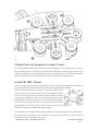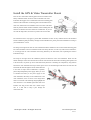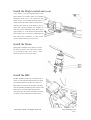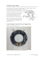
1
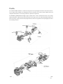
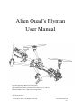
Alien Quad’s Flyman
User Manual
Special Lightweight Multi-rotor Helicopters
Special Brushless gimbal Customized for Gopro Hero 2 or Hero3
Recommended Camera: Gopro Hero3,Gopro Hero2
V1.00
2013.0823 Revision
Aliencopter Studio All Rights Reserved.
www.aliencopter.com
1/31
Disclaimer
Thank you for purchasing this aliencopter studio product, please regularly visit the Flyman
Multi-rotor web page at www.aliencopter.com, which is updated regularly more detail. Product
information,technical updates and manual corrections will be available on the website.Due to
unforeseen changes or product upgrades,the information contained in the manual is subject to
change without notice.
Read this disclaimer carefully before using this product. By using this product, you hereby agree
to this disclaimer and signify that you have read them fully. Please strictly follow the manual to
assemble and use the product. The manufacturer and seller assume no liability for any resulting
damage or injury arising from the operation or use of this product.
This product and manual are copyrighted by Aliencopter studio with all rights reserved.
No part of this product or manual shall be reproduced in any form without
the prior written consent or authorization of DJI Innovations. No patent liability is assumed with
respect to the use of the product or information contained herein.
Aliencopter Studio All Rights Reserved.
www.aliencopter.com
2/31
Profile
The ALIENCOPTER FLYMAN is a multi-rotor designed for aerial photograph which Pure carbon fiber structure,
Clever designs make assembly and configuration become especially easy and fast; protrate foldable frame and
collapsible GPS Mount are conveniently portable for optimal user experiences.
The brushless gimbal had 245 drgree super vision which to create omnidirectional aerial view and high
quality photograph. Combined with professional multi-rotor autopilot system, The ALIENCOPTER FLYMAN will
achieve hovering, cruising and other steady flight elements, which can be applied for aerial photography and other
aero-modeling activities.
Aliencopter Studio All Rights Reserved.
www.aliencopter.com
3/31
Contents
Disclaimer .........................................................................................................................................2
Profile................................................................................................................................................3
Contents ............................................................................................................................................4
Product Usage Cautions ....................................................................................................................5
Assembly Cautions....................................................................................................................5
Flight Cautions ..........................................................................................................................6
Technical Foreword...........................................................................................................................7
Compare Products .............................................................................................................................8
In The Box.........................................................................................................................................9
The Kit parts......................................................................................................................................9
main Component Parts .................................................................................................................... 11
Tools Needs.....................................................................................................................................12
Main Frame Setup...........................................................................................................................13
The First step: Front Frame Setup ......................................................................................13
The Second Step:Back Frame setup ....................................................................................14
The Third Step: Bartty Package Frame setup ....................................................................15
The Fourth Step: Mount Simple Landing Gear .................................................................16
The Final Step:Mount Brushless gimbal .............................................................................17
Attach Electric Equipment to main Frame ......................................................................................20
Install the IMU Mount ............................................................................................................20
Install the GPS & Video Transmitter Mount ...........................................................................21
Install the Flight control and so on..........................................................................................22
Install the Motor......................................................................................................................22
Install the BEC ........................................................................................................................22
Install The Lipo Bartty ............................................................................................................23
Install Gimbal Control & Power Supply Hub .........................................................................23
Full Installed Flyman Frame ...........................................................................................................24
Ready For The First Flight ..............................................................................................................25
Brushless gimbal Testing ........................................................................................................25
YS-X4 Flight Control Testing .................................................................................................27
Pre-flight Checks and Tuning..........................................................................................................29
Important Notes for Flight ..............................................................................................................30
Appendix.........................................................................................................................................31
Aliencopter Studio All Rights Reserved.
www.aliencopter.com
4/31
Product Usage Cautions
The ALIENCOPTER FLYMAN is not a toy and should beoperated with extreme care, as improper operation can
cause serious personal injury and damage to property. When flying, the fast rotating propellers may cause serious
damage(s) and injuries. Therefore, please fly with a high safety in mind at all time.
The ALIENCOPTER FLYMAN should not be flown over or around people, power lines or other aircraft. It is
important to always check The ALIENCOPTER FLYMAN and its components prior to operation. Always
maintain a safe distance fromThe ALIENCOPTER FLYMAN when in use. Never attempt to touch it when the
propellers are moving. As with any multi-rotor helicopter, The ALIENCOPTER FLYMAN is a complax and
technical machine. Novice pilots should invest sufficient time on a flight simulator and seek training from an
experienced pilot prior to operation. A flight simulator is nosubstitute for training with an experienced pilot,
particularly when it comes to learning how to safely operate The ALIENCOPTER FLYMAN. Novice pilots should
never fly without the supervision of an experienced pilot.
Always remove the props when you are making a change to the configuration of The ALIENCOPTER FLYMAN.
Always test The ALIENCOPTER FLYMAN with the props removed to make sure that the motors are spinning in
the correct direction and that the motor assignment is correct with respect to your flight control board. If you have
either of these wrong. The ALIENCOPTER FLYMAN will be uncontrolled and dangerous.
Aliencopter studio disclaims all warranties, whether express or implied, including but not limited to the implied
warran-ties or merchantability and fitness for a particular purpose. Airtechno does not assume any liability,
whether direct, indirect, special, incidental, punitive, contingent or consequential damages to persons or property
caused by The ALIENCOPTER FLYMAN. In no event shall Airtechno be liable for personal injury up to and
including
death.
It’s your responsibilty to perform a full system check of The ALIENCOPTER FLYMAN prior to flight. As
Aliencopter Studio can not control every operations of the users, like assembly, final assembly, refit or
inappropriate operation, the follow consquences or damages caused by above actions have nothing to do with
Aliencopter Studio. It’s your responsibilty to learn how to safely operate The ALIENCOPTER FLYMAN and to
adhere to all applicable rules and regulations. Fly at your own risk
Assembly Cautions
(1) Mount the GPS Module with a bracket, to avoid interference with the power board of main frame.
(2) For IMU mounting, make sure the arrow direction marking on the IMU is pointing to the aircraft nose.
(3) The receiver is strongly recommended to be attached under the bottom board of center frame, and the Head of
antenna is downward without any obstacle. Otherwise the aircraft may be out of control, since the wireless
signal may be lost.
(4) Mount the arms correctly.
a)
front Arm installed in front frame
b)
back Arm installed in back frame
(5) For removing screws in the bottom board, please proceed with cautious, avoiding damages. Do not remove
any other screws fixed with glue.
(6) Notice matching the indications is very important, please pay attention to them.
Aliencopter Studio All Rights Reserved.
www.aliencopter.com
5/31
Flight Cautions
(1) With YS-X4 or Other autopilot system, make sure the output signal of F1~F2 and M1~M6 are all
normal, to avoid serious damages and injuries.
(2) Keep flying the multi-rotor a distance from people, building, high-voltage lines, tall trees, water,
etc.
(3) Make sure to use 4S LiPo battery for power supply.
(4) Do not get close to or touch the working motors and propellers, which will cause serious injury.
(5) Do not over load the multi-rotor.
(6) Make sure the propellers and the motors are installed correctly and firmly before flying.
(7) Make sure all parts of product are in good condition before each flight. Do not fly with wore or
broken parts.
(8) Strongly recommend you to use Aliencopter Studio parts as much as possible.
Aliencopter Studio All Rights Reserved.
www.aliencopter.com
6/31
Technical Foreword
Below are a few tips from the designers to aid in assembly, flght and maintenance of the ALIENCOPTER
FLYMAN.
ALIENCOPTER FLYMAN is designed to be a lightweight lift multi-totor helicopter. As such, it is very important
totake your time and assemblr with care.
Here are a few important tips in assembling the ALIENCOPTER FLYMAN:
1)
Locknuts are needed in installing motor mounts. Make sure to install the screws tightly into the plate and
through locknuts, in case the locknuts would loosen when meet vibration. A lot of press nuts are needed to be
installed into the main frame plates, this kind of nuts will not loosen in normal conditions, but you
shouldalways install the screws tightly.
2)
Be careful working with carbon fiber booms and frame. Carbon fiber has sharp edges which can cur your
fingers and/or chafe delicate electronic wires.Any time a wire has to make a bend around the carbon fiber
booms or frame, we recommand using some kind of protective sleeve(e.g. shrink tubing,nylon braid,etc.).
Carboin fiber is also conductive, so it is very important to make sure that a flight components are
appropri-ately insulated.
3)
Always remove the props when you are making a change to the configuration of the ALIENCOPTER
FLYMAN. We always recommend first testing the ALIENCOPTER FLYMAN with the props removed to
make sure that all the motors are spinning in the correct direction, or ALIENCOPTER FLYMAN will
become uncontrolled and dangerous. Mismatch any two wires out of the three wires of the motor, the
spinning direction will be changed. You may look up how to make the motors spin in the right direction in
the instruction book of your flight control board.
4)
For different flight control system, there are different requirements in assembly and debugging. Always
assemble and debug the control system and the machine in accordance with your selected flight control
system.
Aliencopter Studio All Rights Reserved.
www.aliencopter.com
7/31
Compare Products
Key
DJI phantom
DJI S800
Aliencopter Flyman
Duration
10~15min
10~16min
10~18min
Battery
2200mah
10000mah~15000mah
5200mah~10000mah
Features
capacity
Dimensions
Weight
BASIC
Operating Temperature
-10°C ~ 50°C
Operating
PARAMETERS
Take-off Weight
<1000G
Temperature
Hovering Accuracy
Vertical: ± 0.8m
Take-off Weight
5KG~7KG
warm if you want to use it
(GPS Mode)
Horizontal:±2.5m
Hovering Accuracy
Vertical: ± 0.8m
under
Max Tilt Angle
45°
(GPS Mode)
Horizontal:±2.5m
could be -10°C or lower)
Max Ascent / Descent
±6m/s
Max Tilt Angle
45°
Take-off Weight
2.5KG~3.5KG
±6m/s
Hovering
Vertical: ± 0.5m
Accuracy
Horizontal:±2m
Speed
Max
-5°C to +60°C
Ascent
/
Operating
-10°C to +60°C
Temperature
(You have to keep the IMU
Max Flight Velocity
10m/s
Descent Speed
Diagonal
350mm
Max Flight Velocity
10m/s
(GPS Mode)
(motor center to motor
Diagonal
800mm
Max Tilt Angle
35°
center)
(motor
Max Ascent /
±6m/s
distance
distance
center
to
motor center)
low
temperature,
Descent Speed
Max
Flight
10m/s
Velocity
Diagonal
600mm
distance (motor
center to motor
center)
TX
Working Frequency:2.4GHz ISM;
Working Frequency:2.4GHz ISM;
Working Frequency:2.4GHz ISM;
PARAMETERS
Control Channels:6 Channels;
Control Channels:8 Channels;
Control Channels:8 Channels;
Communication Distance 300m;
Communication Distance 1000m;
Communication Distance 1000m;(maybe more)
Gimbal
No
Three Axis ZENMUSE GIMBAL Z15
Two Axis Brushless gimbal
AP stability
No
Very stabilizing
Good stabilizing
Aerial Photography
Aliencopter Studio All Rights Reserved.
www.aliencopter.com
8/31
Shooting vision
Very small vision - Under Propeller and landing Gear
Nice vision - Under Propeller
Super vision - Never see Propeller and landing Gear
FPV
To but not for
To but not for
To be for
Air attitude
No Clearly
No Clearly
Very Clearly
Portable
Small and All in one
disassembly
Fold
Airline
To but not for
Good but not for turning
Good and for turning
Diy Space
No
No
A lot of Space
Black Box
No
No
Have it (last 1 min flight Data)
Adjustable
Need PC and link Flight Controller
Need PC and link Flight Controller
Wifi and Mobile only
parameters
In The Box
The Kit parts
Number
Type
SN
Name
PCS
1
main frame
FA410001
IMU Mount Board
1
2
FA410002
16mm Motor Mount Board
4
3
FA410003
Simple Landing Gear
4
4
FA410004
M3*16mm Motor Mount Carbon Pad
4
5
FA410005
Front Upper Carbon Frame
1
6
FA410006
7
FA410007
Front Bottom Mount Carbon Plate
1
8
FA410008
Back Upper Carbon Frame
1
9
FA410009
Back Bottom Carbon Pad
1
10
FA410010
25mm Motor Mount Carbon Pad
1
11
FA410011
16*236mm Front Carbon Tube
2
12
FA410012
16*323mm Back Carbon Tube
2
13
FA410013
25*234mm Link Main Fream Carbon Tube
1
14
FA410014
Battery Package Carbon Frame
1
15
FA410015
25*250mm Battery Balance Carbon Tube
1
16
FA410016
Front Upper intensive Carbon Frame
1
17
FA410017
Gimbal damping Upper Carbon Frame
1
18
FA410018
electrical installations Mount Carbon
Pad
1
19
FA410019
Back Bottom Carbon frame
2
Front Bottom Carbon Frame
Aliencopter Studio All Rights Reserved.
2
www.aliencopter.com
9/31
20
FA410020
Gimbal Control Panel Upper shell
1
21
FA410021
Brushless
1
22
FA410022
Camera Mount Plate
1
FA410023
Gimble Cantilever Arm
1
FA410024
Camera Gravity Cross Plate
1
FA410025
4215 Motor for Brushless Gimbal
2
26
FA410026
Gimbal Control Panel & IMU Sensor
1
27
FA410026
1
DCDC Power Supply Module
1
FA410027
16mm Tube Clip
4
FA410028
16mm C Type Tube Clip
8
30
FA410029
6mm Silicone Damper
4
31
FA410030
16mm CNC Tube Clip
10
32
FA410031
M3 Embedded Nut
8
33
FA410032
25mm Plastic Tube Clip
9
34
FA410033
10mm Silicone Damper
8
35
FA410034
Power Supply Hub
1
36
FA410035
M4*7*30MM Nylong Hex Bolt
12
37
FA410036
8mm M2.5 Countersun Head Screw
6
38
FA410037
6mm M2.5 Countersun Head Screw
20
39
FA410038
14mm M2.5 Countersun Head Screw
8
40
FA410039
30mm M2.5 Countersun Head Screw
28
41
FA410040
M2.5 Hexagon screws
24
42
FA410041
6mm M3 Nylong Screw
8
43
FA410042
Gimbal Roll and pitch Data Cables
2
44
FA410043
10mm M3 Plasstic Screw
8
45
FA410044
40mm M3 Cup Screw
28
46
FA410045
M3 Hexagon Self Locking Nut
30
47
FA410046
5mm Nylong Plastic Bolt
4
48
FA410047
10mm Nylong Plastic Bolt
8
49
FA410048
25mm Nylong Plastic Bolt
4
50
FA410049
M3 Plastic Nut
6
51
FA410050
30mm M3 Screw
4
52
FA410051
Black Plastic Cable Tie
23
24
25
28
29
Brushless
gimbal&acce
ssories
Screw &
parts Kit
Aliencopter Studio All Rights Reserved.
Gimbal Roll Arm
Several
www.aliencopter.com
10/31
53
FA410052
M3 Inner Hexagon Spanner
1
54
FA410053
IMU Foam Double Sided Adhesive Tape
1
55
FA410054
Sticker
1
56
FA410055
Landing Gear Sponge Tube
1
57
FA410056
T Type Slope Indicator
1
58
FA410057
Self Adhansive Tape
1
59
FA410058
Gopro3 Data Cable
1
60
FA410059
Video Transmitter JST Cable
1
61
FA410060
Signal Sheilding Cable
1
62
FA410061
20mm M2.5 Countersun Head Screw
4
63
FA410062
M2.5 shims
4
64
FA410063
M4*7*6mm Nylong Plastic Bolt
10
65
FA410063
1
M4*7*22mm Nylong Plastic Bolt
10
ARF Parts List
main Component Parts
Front Frame×1
Back Frame×1
Front Frame 16*236mm Arm×2
Back Frame 16*323mm Arm×2
Link Main Frame 25mm Pipe×1
LiPo Battery Balance 25mm Pipe×1
Aliencopter Studio All Rights Reserved.
www.aliencopter.com
11/31
Simple Front Landing Gear×2
LiPo Battery Packge Frame×1
Gopro Hero Brushless gimbal×1
Screw & parts Kit
Tools Needs
No.
Tools name
1
2.00mm Hex Wrench and 2.5mm Hex Wrench
For mounting screws
2
Thread Locker
For fastening screws
3
Nylon Cable Tie
4
Scissors
5
Diagonal Cutting Pliers
6
Foam Double Sided Adhesive Tape
Aliencopter Studio All Rights Reserved.
Usage
For mounting IMU and so on
www.aliencopter.com
12/31
Main Frame Setup
The First step: Front Frame Setup
Aliencopter Studio All Rights Reserved.
www.aliencopter.com
13/31
The Second Step:Back Frame setup
Aliencopter Studio All Rights Reserved.
www.aliencopter.com
14/31
The Third Step: Bartty Package Frame setup
Aliencopter Studio All Rights Reserved.
www.aliencopter.com
15/31
The Fourth Step: Mount Simple Landing Gear
Aliencopter Studio All Rights Reserved.
www.aliencopter.com
16/31
The Final Step:Mount Brushless gimbal
1.
First, install the Gorpro Hero camera on the brushless gimbal. Gopro Hero 3 needs to be installed in the
default installation position. If it is Gorpro Hero 2 camera that you choose, you can install it by adjusting the
screws on the swashplate of the pitching motor, as you can see from the image below, until the camera
reaches a balanced position. Based on our experience, the screws are usually installed on the upper and rear
Aliencopter Studio All Rights Reserved.
www.aliencopter.com
17/31
position to the center of the swashplate.
Aliencopter Studio All Rights Reserved.
www.aliencopter.com
18/31
Please click here to view the Gimbal Installation Video Guide.
2.
When you install Gopro gimble,please make sure that the gravity center of the gimbal suspension arm,
which is curving at the top, is right on the center of the vibration absorption carbon-fiber plate. Please note
that there might be slight differences between the positions of Gopro 2 and Gopro 3 at top, as shown in the
image below.
Aliencopter Studio All Rights Reserved.
www.aliencopter.com
19/31
Attach Electric Equipment to main Frame
The ALIENCOPTER FLYMAN pack includes only the gimbal and the main frame. Therefore, please consult your
electric equipment providers for specific requirements before assembling under the following instructions. The
suggestive assembling instructions provided in this document only apply under the most common circumstances.
Aliencopter Studio shall bear no responsibility for any electric products that are not provided by us.
Install the IMU Mount
There are two types of IMU installation, the installation of integrated IMU and independent IMU, which share the
same installation solutions. This document will elaborate only on independent IMU installation.
The IMU mounting plate needs to be fixed on 4 anti-vibration rubber balls, the
size of which fits most of the flight controls or IMU. During installation, attention
needs to be paid to the direction in which IMU should be installed. In the image
on the right, the triangular arrow icon points to the direction where the aircraft is
heading and IMU needs to be installed in the center of the IMU mounting plate, as
this is also the center of the main frame. The image below displays the correct
IMU installation. The red arrow points to the front of IMU, and also the same
direction the triangle arrow on IMU mounting plate pointing to
The instructions above only apply to IMU installation under most circumstances. If there are any conflicts between
this document and the installation guide provided by the flight control manufacturers, please proceed the
installation according to your manufacturers’ version.
Aliencopter Studio All Rights Reserved.
www.aliencopter.com
20/31
Install the GPS & Video Transmitter Mount
There are two carbon-fiber mounting plates need to be installed on the
battery installation frame, which are used to hold GPS or the video
transmitter. We suggest users to install GPS on the front mounting plate,
while the video transmitter on mounting plate in the back. Because in
most cases, GPS needs to be installed as near to the center of the main
frame as possible. Similar to IMU installation, when installing GPS, the
direction of GPS also needs to be taken into consideration. As you can
see from the image below, the red arrow points to the front of GPS.
The instructions above only apply to general IMU installations. If there are any conflicts between this document
and the installation guide provided by the flight control manufacturers, please proceed the installation according to
your manufacturers’ version.
The image on the right shows how the video transmitter should be installed on the rear carbon-fiber mounting plate.
The video transmitter needs to be installed with the wire facing the back, as in this way under most circumstances,
it can help prevent the video transmitter from being blocked by the main frame, thus expanding the effective
transmission range.
The image on the right shows the installation position and direction of the video transmitter. Please use 3M
double-sided tapes in the Screw & Parts kit to hold the video camera and carbon-fiber mounting plate together, and
at the same time, use plastic zip ties to make them firmly fastened. Considering the comparatively long distance
between the video transmitter and Gopro camera, please use 2-core shielded signal cable in the Screw & Parts kit
and install the cable through the 25mm carbon-fiber tube
to the front of Gopro camera. Meanwhile, if possible,
please adopt independent power supply. When you use a
3s 850mah LiPo battery as the power supply for the
video transmitter, the battery can be installed next to the
video transmitter, as the red arrow in the image below
shows. The red line in the following image highlights the
route where the 2-core shielded signal cable needs to be
installed. You may put the cable into a harder cooper
wire or a slim tube to help it pass through the
carbon-fiber tube.
Aliencopter Studio All Rights Reserved.
www.aliencopter.com
21/31
Install the Flight control and so on
If you decide to use the integrated flight control,
please install it on the IMU mount. For installation
instructions, please refer to the “Install the IMU
Mount” section. As for independent flight control, it
usually comes with a main control device and there’s a
mounting plate below the main frame for users to
install more optional equipment, for example, the
main control device, OSD, LED control, DCDC power
supply module, etc.. as the following image indicates.
This document only uses images to demonstrate the
main control device installation. For other devices,
you may install according to your own needs.
Install the Motor
During motor installation, please make sure to keep
the motor flat and the wire outlets facing outside.
As the following image shows, there’s a bezel
outside the motor set to protect the outlets。
Install the BEC
The BEC installation needs wires connecting to the 4
motors set on both the front and back arms. The signal
wires should be linked to the main control device or
IMU mount. The red arrows in the image on the right
show the ideal BEC installation position. Motors on the
front arms are connected to BEC through 25mm
carbon-fiber tube, while wires of the back arms motors
can directly connect to BEC below the back frame.
Aliencopter Studio All Rights Reserved.
www.aliencopter.com
22/31
Install The Lipo Bartty
The main purpose of installing the LiPo battery is to adjust the center of gravity of the whole frame and try to keep
the frame’s center and its center of gravity overlapped on the back frame. Therefore, LiPo battery installation
should be the last step of the whole frame assembly, which
can only be done with all the wires and equipment installed
and Gopro Hero camera tuned. As shown in the image on
the right, the red arrows indicate the screws that need to be
loosed, which help tuning the back-and-forth position of
battery after installation. The image below shows the
innermost of the 25mm carbon-fiber tube, and the
outermost end located two rows of retaining plates。The
battery we used for testing and tuning is 4S 5800mah LiPo
battery. Once the battery reaches the balancing point, you
can adjust the height of the upper retaining plate, as the
following image shows.
Install Gimbal Control & Power Supply Hub
How to use it as the following image shows.
How to install it inside to the Flyman frame as the following image shows.
Aliencopter Studio All Rights Reserved.
www.aliencopter.com
23/31
Full Installed Flyman Frame
Below is the image of a Flyman Frame with most of the electric equipment installed, for your reference.
Aliencopter Studio All Rights Reserved.
www.aliencopter.com
24/31
Ready For The First Flight
Brushless gimbal Testing
1.
1.To make sure that the gimbal control board cable, sensor board cable and power cable are working
properly. If so, cut off the power cable first, then connect USB cable to the control board to see if the
gimbal is properly connected to your PC, and if the control board drive has been installed. If you have
not yet installed the control board drive on you PC, please click here to visit AlienCopter’s official
website to download and install the drive. Please note that there are two versions for the control board
drive, working on x86 and x64 operating system respectively. You may install the version that is
compatible with the operating system you are using.
2.
Open the gimbal configuration interface, select “COM” port in the dropdown list under “Connect” tab,
and then click on “connect”. In normal conditions, your PC will successfully connect to the gimbal
control board via COM port and read the default parameters. Before leaving the factory, the optimal
parameters for the control have been set. For Gopro Hero3 camera, you don’t have to reconfigure the
parameters. You just need to select “Load” in the dropdown list under “Profile” tab, which is on the
interface’s upper-right corner, find the default setting files and then reload the default parameters. If
you are using Gopro Hero2, please configure the parameters according to your need. The image below
is for your reference. For more details, please click here to view the videos.
Aliencopter Studio All Rights Reserved.
www.aliencopter.com
25/31
Aliencopter Studio All Rights Reserved.
www.aliencopter.com
26/31
YS-X4 Flight Control Testing
If you are going to test YS-X4 for the first time, please firstly check if the flight control has been installed, as
shown in the image below.
Connect to WiFi hotspot SSID: ZERO-TECH, Default Password: 82890430. Once the WiFi connection is
established, please complete the necessary settings and checks according to YS-X4 user manual. The link of its
official website is http://www.zerouav.com/en/Product/chanpinxilieyi/222.html. You can also download
the user manual and configure software on AlienCopter’s website. For the first-time installation, please refer to the
Aliencopter Studio All Rights Reserved.
www.aliencopter.com
27/31
“Installation Guide” on the last slide page of the YS-X4 ground station’s “Set” sheet, as shown in the image below.
Please keep testing until the flight control parameters appearing on the ground station get normal, as the image
below shows.
Aliencopter Studio All Rights Reserved.
www.aliencopter.com
28/31
If you are using our recommended types for the motor and propeller, which are 4108, kv600, apc1238 (for
propeller), please configure the sensor parameter on the ground station’s “Param” sheet once the initialization
completes. Please pay attention to the parameters in the image below.
Please It is very important to note that in the first vertical row in the image above, the Roll Sensitivity should
be set to 45, Pitch Sensitivity to 80 and Sway Compensation to 80(as the image shows). As for the Magnetic
Declination parameter, you need to set the number based on the magnetic declination of your location. Take
Shenzhen, China for instance, the Magnetic Declination parameter should be set to 2.0. Cell Number indicates the
number of battery cells. 4s battery is the type we recommend. You may leave other parameter settings as default. In
the second vertical row, you need to set “Aircraft Type” to “Quad-Rotor X” and leave other parameter settings as
default.
Pre-flight Checks and Tuning
1.
First, check the 4 motors to see if they rotate in the correct direction; if the motor plugs of the flight
control are properly plugged (Motor 1-Motor 4); and if the propellers are correctly installed. Arrows in
the image below show the correct direction in which the motors should rotate.
Aliencopter Studio All Rights Reserved.
www.aliencopter.com
29/31
2.
Second, make sure that the brushless gimbal remains flat during the its first power-up after the
installation of Gopro 2 or Gopro3。
Important Notes for Flight
1.
Because of the extraordinary design of the aircraft’s main frame, it has some unique features in flight. The
aircraft is quite good at high-speed flight and steep turns. Its center of gravity is not on the center of the
central plate。Therefore, when it flies steep turns in high speed, it needs to make a certain angle. In most
cases, when you flip the direction switch on the remote control, you need to add a certain amount of aileron
rudder, in order to achieve the flight performance similar to the fixed-wing aircrafts. For this reason, the
video recorded by this aircraft is very sharp and vivid, unlike those taken by the standard multi-rotor aircrafts,
which is more rigid.
Aliencopter Studio All Rights Reserved.
www.aliencopter.com
30/31
Appendix
Aliencopter Studio All Rights Reserved.
www.aliencopter.com
31/31