1
Decoded Output
1998 Welch Allyn, Inc. All rights reserved.
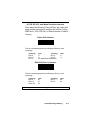
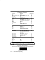
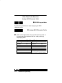
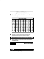
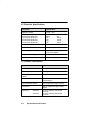
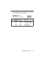
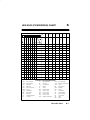
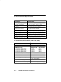
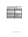
Input Power Voltage Requirements
Model
Input Power Voltage
3400XX–X0
3400XX–X2
3400XX–18
5 Volt ONLY
3400X–X1
3400X–X3
5 Volt Standard Cables or
12 Volt Special Cables
!
Disclaimer
Welch Allyn reserves the right to make changes in specifications
and other information contained in this document without prior
notice, and the reader should in all cases consult Welch Allyn to
determine whether any such changes have been made. The
information in this publication does not represent a commitment on
the part of Welch Allyn.
Welch Allyn shall not be liable for technical or editorial errors or
omissions contained herein; nor for incidental or consequential
damages resulting from the furnishing, performance, or use of this
material.
This document contains proprietary information which is protected
by copyright. All rights are reserved. No part of this document
may be photocopied, reproduced, or translated into another
language without the prior written consent of Welch Allyn,
Incorporated.
This device complies with part 15 of the FCC Rules. Operation is subject to the
following two conditions: (1) this device may not cause harmful interference,
and (2) this device must accept any interference received, including
interference that may cause undesired operation.
FCC Class B Compliance Statement
This equipment has been tested and found to comply with the limits for a Class B
digital device pursuant to part 15 of the FCC Rules. These limits are designed to
provide reasonable protection against harmful interference in a residential
installation. This equipment generates, uses, and can radiate radio frequency
energy and, if not installed and used in accordance with the instructions, may
cause harmful interference to radio communications. However, there is no
guarantee that interference will not occur in a particular installation. If this
equipment does cause harmful interference to radio or television reception,
which can be determined by turning the equipment off and on, the user is
encouraged to try to correct the interference by one or more of the following
measures:
• Reorient or relocate the receiving antenna.
• Increase the separation between the equipment and receiver.
• Connect the equipment into an outlet on a circuit different from that to which
the receiver is connected.
• Consult the dealer or an experienced radio or television technician for help.
Caution: Any changes or modifications made to this device that are not
expressly approved by Welch Allyn, Inc. may void the user’s authority to
operate the equipment.
Note: To maintain compliance with FCC Rules and Regulations, cables
connected to this device must be shielded cables, in which the cable shield
wire(s) have been grounded (tied) to the connector shell.
Canadian Notice
This equipment does not exceed the Class B limits for radio noise emissions as
described in the Radio Interference Regulations of the Canadian Department of
Communications.
Le present appareil numerique n’emet pas de bruits radioelectriques depassant
les limites applicables aux appareils numeriques de la classe B prescrites dans
le Reglement sur le brouillage radioelectrique edicte par le ministere des
Communications du Canada.
!
Caution:
DO NOT use SCANTEAM 3000 or 5500 12 Volt Interface Cables with the
SCANTEAM 3400. DAMAGE TO YOUR 3400 WILL RESULT!
Use the appropriate 3400 12 Volt Interface Cable.
The CE mark on the product indicates that the system has been tested to
and conforms with the provisions noted within the 89/336/EEC
Electromagnetic Compatibility Directive and the 73/23/EEC Low Voltage
Directive.
European Contact:
European Regulatory Manager
Welch Allyn Ltd.
28 Sandyford Office Park
Foxrock, Dublin 18
Ireland
or
Welch Allyn, Ltd.
1st Floor
Dallam Court Dallam Lane
Warrington, Cheshire WA2 7LT
England
Welch Allyn shall not be liable for use of our product with equipment
(i.e., power supplies, personal computers, etc.) that is not CE marked and
does not comply with the Low Voltage Directive.
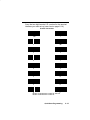
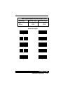
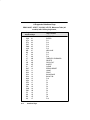
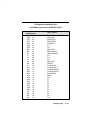
TABLE OF CONTENTS
Chapter 1
Getting Started
Section
Page
1.1
1.2
1.3
1.4
1.5
1.6
1–1
1–2
1–3
1–4
1–6
1–6
Introduction to the 3400 . . . . . . . . . . . . . . . . . . . .
Unpacking the Scanner . . . . . . . . . . . . . . . . . . . . .
Scanner Identification Label . . . . . . . . . . . . . . . . .
Connecting the Scanner . . . . . . . . . . . . . . . . . . . .
Scanning Techniques . . . . . . . . . . . . . . . . . . . . . .
Scanning Performance . . . . . . . . . . . . . . . . . . . . .
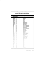
Chapter 2
Quick Start Programming Menu
Section
Page
2.1 Introduction . . . . . . . . . . . . . . . . . . . . . . . . . . . . . . .
2.2 “Plug and Play” (Single Scan) Programming . .
❖ Programming Instructions . . . . . . . . . . . . . .
❖ IBM PC Interface . . . . . . . . . . . . . . . . . . . . . .
❖ IBM 4683 Ports 5B, 9B, 17 Interface . . . . .
❖ OCIA Interface . . . . . . . . . . . . . . . . . . . . . . . .
❖ OCR, RS–232, Wand Emulation Interface
2.3 Terminal Selection Programming . . . . . . . . . . . .
❖ Programming Instructions . . . . . . . . . . . . . .
❖ Supported Terminals . . . . . . . . . . . . . . . . . . .
❖ Terminal Selection Menu . . . . . . . . . . . . . . .
2.4 Program Carriage Return Suffix . . . . . . . . . . . . .
2.5 Clear Bar Code Suffix . . . . . . . . . . . . . . . . . . . . . .
2.6 Reset Factory Settings . . . . . . . . . . . . . . . . . . . . .
2–1
2–2
2–2
2–5
2–6
2–7
2–9
2–11
2–11
2–14
2–14
2–18
2–18
2–18
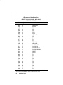
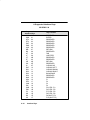
Chapter 3
Additional Programming Selections
Section
Page
3.1 Introduction . . . . . . . . . . . . . . . . . . . . . . . . . . . . . . .
❖ Programming Instructions . . . . . . . . . . . . . .
❖ Global Programming Bar Codes . . . . . . . . .
3–1
3–2
3–3
Table of Contents
i
Chapter 3
ii
Additional Programming Selections, continued...
Section
Page
3.2 Bar Code Prefix and Suffix Programming . . . . .
❖ Bar Code Prefix Selection . . . . . . . . . . . . . .
❖ Bar Code Suffix Selection . . . . . . . . . . . . . .
3.3 Dual Interface Programming . . . . . . . . . . . . . . . .
❖ Code 39 Wand Emulation Selection . . . . .
❖ Same Code Wand Emulation Selection . .
❖ RS–232 Selection . . . . . . . . . . . . . . . . . . . . .
❖ Laser Emulation Selection . . . . . . . . . . . . . .
❖ Primary Interface only Selection . . . . . . . . .
❖ Enable Dual Interface Selection . . . . . . . . .
3.4 Output Programming . . . . . . . . . . . . . . . . . . . . . . .
❖ Beeper Selection . . . . . . . . . . . . . . . . . . . . . .
❖ Keyboard Style Selection . . . . . . . . . . . . . . .
❖ Keyboard Emulation Mode . . . . . . . . . . . . .
❖ Intercharacter Delay Selection . . . . . . . . . .
❖ Interfunction Delay Selection . . . . . . . . . . . .
❖ Intermessage Delay Selection . . . . . . . . . .
❖ Output Mode Selection: . . . . . . . . . . . . . . . .
♦ Buffer Scans . . . . . . . . . . . . . . . . . . . . .
♦ Function Code Transmit . . . . . . . . . . .
♦ Laser Redundancy . . . . . . . . . . . . . . . .
❖ Country Code Selection . . . . . . . . . . . . . . . .
❖ NCR 7052 Keypad Selection . . . . . . . . . . . .
3.5 Industrial Symbology Programming . . . . . . . . . .
❖ Codabar Selection . . . . . . . . . . . . . . . . . . . . .
❖ Code 39 Selection . . . . . . . . . . . . . . . . . . . . .
❖ Interleaved 2 of 5 Selection . . . . . . . . . . . . .
❖ Code 2 of 5 Selection . . . . . . . . . . . . . . . . . .
❖ Matrix 2 of 5 Selection . . . . . . . . . . . . . . . . .
❖ Code 11 Selection . . . . . . . . . . . . . . . . . . . . .
❖ Code 93 Selection . . . . . . . . . . . . . . . . . . . . .
❖ Code 128 Selection . . . . . . . . . . . . . . . . . . . .
❖ Disable All Symbologies . . . . . . . . . . . . . . . .
3–4
3–5
3–12
3–16
3–18
3–18
3–18
3–18
3–19
3–19
3–20
3–21
3–22
3–25
3–26
3–26
3–26
3–28
3–28
3–29
3–31
3–32
3–34
3–35
3–36
3–40
3–43
3–45
3–46
3–47
3–49
3–50
3–51
Table of Contents
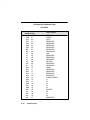
Chapter 3
Additional Programming Selections, continued...
Section
Page
3.6 Retail Symbology Programming . . . . . . . . . . . . .
❖ UPC Selection . . . . . . . . . . . . . . . . . . . . . . . .
❖ EAN Selection . . . . . . . . . . . . . . . . . . . . . . . .
❖ UPC & EAN Addenda Selection . . . . . . . . .
❖ MSI Selection . . . . . . . . . . . . . . . . . . . . . . . . .
❖ Plessey Selection . . . . . . . . . . . . . . . . . . . . .
❖ Disable All Symbologies . . . . . . . . . . . . . . . .
3.7 RS–232 Programming . . . . . . . . . . . . . . . . . . . . . .
❖ Baud Rate Selection . . . . . . . . . . . . . . . . . . .
❖ Parity Selection . . . . . . . . . . . . . . . . . . . . . . .
❖ Data Format Selection . . . . . . . . . . . . . . . . .
❖ CTS Handshake Selection . . . . . . . . . . . . . .
❖ Serial Wedge Selection . . . . . . . . . . . . . . . .
❖ Protocol Selection . . . . . . . . . . . . . . . . . . . . .
3.8 Data Formatter (Bar Code Editor) Programming
❖ Format Editor Selection . . . . . . . . . . . . . . . .
❖ Require Data Format . . . . . . . . . . . . . . . . . .
❖ Delete All Formats . . . . . . . . . . . . . . . . . . . . .
3.9 Trigger and Reread Delay Programming . . . . . .
❖ HHLC Power Up Delay Selection . . . . . . . .
❖ Trigger Mode Selection . . . . . . . . . . . . . . . .
❖ Reread Delay Selection . . . . . . . . . . . . . . . .
❖ Good Read Delay Selection . . . . . . . . . . . .
3.10 Wand Emulation and Laser Output Programming
❖ Output Polarity Selection . . . . . . . . . . . . . . .
❖ Transmission Rate Selection . . . . . . . . . . . .
❖ Data Sync / Wake Up Selection . . . . . . . . .
3.11 Status Check . . . . . . . . . . . . . . . . . . . . . . . . . . . . .
❖ Show Formats . . . . . . . . . . . . . . . . . . . . . . . .
❖ Show Software Revision . . . . . . . . . . . . . . .
3.12
SCANTEAM 3400 Cloning Instructions . . .
3–53
3–54
3–58
3–63
3–64
3–65
3–66
3–68
3–69
3–70
3–71
3–72
3–73
3–74
3–75
3–76
3–79
3–80
3–81
3–82
3–83
3–84
3–85
3–86
3–87
3–88
3–89
3–90
3–90
3–90
3–91
Table of Contents
iii
Chapter 4
Supported Interface Keys
Section
Page
4.1 Keyboard Function Relationships . . . . . . . . . . . .
4.2 Supported Interface Keys . . . . . . . . . . . . . . . . . . .
4–1
4–2
Full ASCII Code 39 Bar Code Chart . . . . . . . . . . . . . .
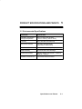
Chapter 5
4–13
Product Specifications and Pinouts
Section
Page
5.1
5.2
5.3
5.4
5–1
5–2
5–2
5–3
5–3
5–4
5–5
5–6
5–8
5–9
5–10
5–11
Environmental Specifications . . . . . . . . . . . . . . . .
Electrical Specifications . . . . . . . . . . . . . . . . . . . .
Scanner Performance . . . . . . . . . . . . . . . . . . . . . .
Pinouts . . . . . . . . . . . . . . . . . . . . . . . . . . . . . . . . . . .
❖ Laser Output only . . . . . . . . . . . . . . . . . . . . .
❖ Standard Laser Cable . . . . . . . . . . . . . . . . . .
❖ Keyboard Wedge . . . . . . . . . . . . . . . . . . . . . .
❖ Wand Emulation . . . . . . . . . . . . . . . . . . . . . .
❖ IBM 4683 Port 5B and Port 17 . . . . . . . . . .
❖ RS–232 . . . . . . . . . . . . . . . . . . . . . . . . . . . . . .
❖ Laser Output . . . . . . . . . . . . . . . . . . . . . . . . .
5.5 General Dimensions . . . . . . . . . . . . . . . . . . . . . . .
Chapter 6
Maintenance and Troubleshooting Guide
Section
Page
6.1 Maintenance . . . . . . . . . . . . . . . . . . . . . . . . . . . . . .
❖ Cleaning the Scan Window . . . . . . . . . . . . .
❖ Inspecting Cords and Connectors . . . . . . .
❖ Replacing the Interface Cable . . . . . . . . . . .
❖ Examining the Scanner Housing . . . . . . . .
6.2 Troubleshooting . . . . . . . . . . . . . . . . . . . . . . . . . . .
6–1
6–1
6–1
6–2
6–2
6–3
Chapter 7
Customer Support
Section
Page
7.1 Obtaining Factory Service . . . . . . . . . . . . . . . . . .
7.2 Technical Support . . . . . . . . . . . . . . . . . . . . . . . . .
7–1
7–3
Appendix A Limited Warranty . . . . . . . . . . . . . . . . . . .
A–1
iv
Table of Contents
Appendix B Hex ASCII (Conversion) Chart . . . . . .
B–1
Appendix C 3400/B and 3400LR/C Information
Section
C.1
C.2
C.3
C.4
C.5
C.6
C.7
C.8
Page
Scanner Identification (3400/B) . . . . . . . . . .
Scanner Identification (3400LR/C) . . . . . . .
Scanning Performance . . . . . . . . . . . . . . . . .
Environmental Specifications . . . . . . . . . . .
Electrical Specifications (3400–XX1, XX2)
Electrical Specifications (3400LR/C) . . . . .
Scanner Performance (3400–XX1, XX2)
Scanner Performance (3400LR/C) . . . . . . .
C–2
C–3
C–4
C–6
C–6
C–7
C–8
C–9
Index
Sample Bar Codes (inside back cover)
Table of Contents
v
vi
Table of Contents
1
GETTING STARTED
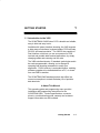
1.1 Introduction to the 3400
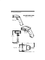
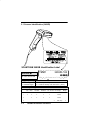
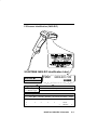
The SCANTEAM 3400 Series CCD is durable and reliable,
easy to hold and easy to aim.
Available with Instant Interface decoding, the 3400 supports
a wide range of interfaces: keyboard wedge, POS terminals,
RS-232, and wand emulation. The 3400 is also capable of
Dual Interface, which lets you use one scanner for POS
terminal and portable data terminal applications, by simply
changing cables and scanning one bar code.
The 3400 autodiscriminates 13 standard symbologies and is
bar code programmable, allowing you to change its
operating and decoding parameters to match your
application. FLASH memory is a standard feature, enabling
software upgrades to be downloaded from a PC, or cloned
from one 3400 to another.
The SCANTEAM 3400 standard product also offers low
current consumption to extend the battery life of portable
data terminals.
❖ About This Manual
This operating guide and programming menu provides
installation and programming instructions for the
SCANTEAM 3400. Product specifications, connector
pinouts, a troubleshooting guide, warranty and customer
support information are also included.
Getting Started
1–1
1.2 Unpacking the Scanner
Open the carton. The shipping carton should contain:
•
Check to make sure everything you ordered is present.
•
Keep the shipping carton to return the scanner for
servicing.
Check for damage during shipment. Report damage
immediately to the carrier who delivered the carton.
•
1–2
Getting Started
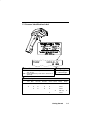
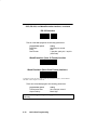
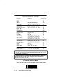
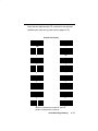
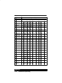
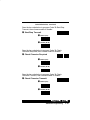
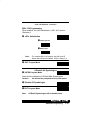
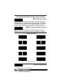
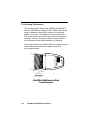
1.3 Scanner Identification Label
ITEM#
3400LR–12
➊ ➋➌
➊
➋ -#". )#"'0) "#*.'/1 !+"#. $-+) /+ /+ !)
-#". &'%& "#*.'/1 !+"#. $-+) !+*/!/ /+ !)
➌
,/'+*
- )%#
.#- 0/
*"
)0(/'+*
2
-0#
2
#1 +-" 2
#"%#
#"%#
-'+0.
-'+0.
0/+ -'%%# *0( -'%%#-
-'+0.
Getting Started
1–3
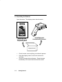
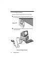
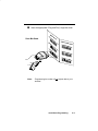
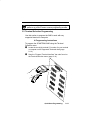
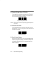
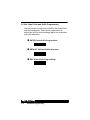
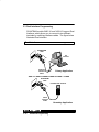
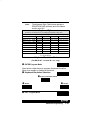
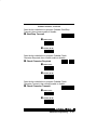
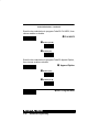
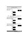
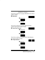
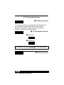
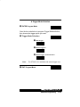
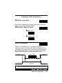
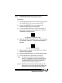
1.4 Connecting the Scanner
Install the scanner by following the steps shown below:
➊
Disconnect power to the terminal/computer by turning
the host system power switch to the “OFF” position.
➋
Connect the interface cable to the scanner and to the
terminal/computer.
3
2
1
1–4
Getting Started
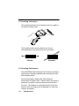
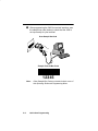
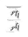
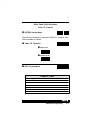
➌
Once the scanner has been fully connected, restore
power to the terminal/computer by turning the host
system power switch to the “ON” position.
➍
You must program the 3400 to work with your terminal
or computer by scanning the appropriate programming
bar code(s). (For further instructions, see Chapter 2,
section 2.2 or 2.3.)
Getting Started
1–5
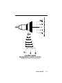
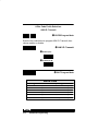
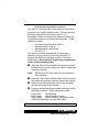
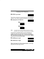
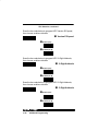
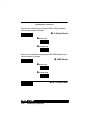
1.5 Scanning Techniques
The scanning technique for a single bar code (on a page or
an object) is shown below.
The illustration below shows where to aim the red
illuminated beam over the bar code for a good read.
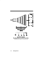
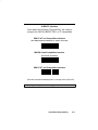
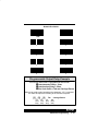
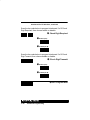
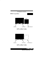
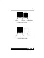
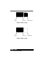
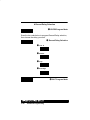
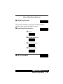
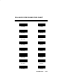
1.6 Scanning Performance
The SCANTEAM 3400 Hand Held CCD Scanner provides a
high first pass scanning capability while assuring bar code
label integrity and life.
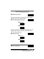
The following figures illustrate the 3400’s Scanner
Performance or depth of field. Depth of field is the range of
distances over which a scanner can accurately decode a
bar code. This distance is measured from the front of the
scanner at the exit window and is dependent on code size,
contrast, and quality.
1–6
Getting Started
4 MIL
.75
1.5
6.6 MIL
.5
.25
0
0
0
1.75
7.5 MIL
10 MIL
13 MIL
20 MIL
2.0
2.20
2.50
2.75
CM.
SCANTEAM 3400HD
Reading Distance and Bar Code Size
(Working zone shown at nominal focus)
Getting Started
1–7
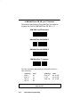
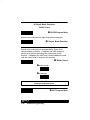
40 MIL
0
8
20 MIL
0
7
13 MIL
1.5
3
7 MIL
6
4.5
CM.
SCANTEAM 3400LR
Reading Distance and Bar Code Size
(Working zone shown at nominal focus)
1–8
Getting Started
QUICK START PROGRAMMING MENU
2
2.1 Introduction
Use this chapter to program the SCANTEAM 3400 Hand
Held CCD Scanner to work with your terminal/computer.
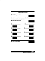
❖ About “Plug and Play” Programming
With “Plug and Play” programming (Section 2.2), you
connect the 3400 and scan only one bar code to program
the scanner (including required prefixes/suffixes).
❖ About Terminal Selection Programming
With Terminal Selection programming (Section 2.3), you
program the 3400 for any supported terminal/computer.
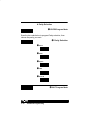
❖ Program Carriage Return (CR) Suffix
Use the single bar code in Section 2.4 to program a
carriage return suffix in the 3400.
❖ To Clear Bar Code Suffix
Use the single bar code in Section 2.5 to clear bar code
suffix in the programmed 3400.
❖ To Reset Factory Default Settings
Use the single bar code in Section 2.6 to reset the 3400
to factory default settings.
❖ Additional Programming Options
If you need additional programming options, refer to
Chapter 3 to configure the 3400 to:
•
•
selective factory default settings
any variation of the programmable features available.
Quick Start Programming
2–1
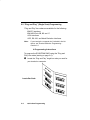
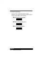
“Plug and Play” (Single Scan) Programming
“Plug and Play” bar codes are available for the following:
IBM PC Interfaces
IBM 4683 Ports 5B, 9B, and 17
OCIA Interfaces
OCR, RS–232, and Wand Emulation Interfaces.
Note:
If your terminal or computer isn’t included in the list
above, see Terminal Selection Programming –
Section 2.3.
❖ Programming Instructions
To program the SCANTEAM 3400 using the “Plug and
Play” bar codes (starting on page 2–5):
➊
Locate the “Plug and Play” single bar code you need for
your terminal or computer.
2–2
Quick Start Programming
➋
Scan the appropriate “Plug and Play” single bar code.
Note:
Programming bar codes will not output data to your
terminal.
Quick Start Programming
2–3
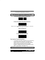
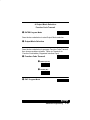
➌
After programming the 3400 for terminal interface, scan
the sample bar code (below) to check that the 3400 is
set up correctly for your terminal.
Sample Code 39 Bar Code
Note:
2–4
Other Sample Bar Codes are inside the back cover of
this Operating Guide and Programming Menu.
Quick Start Programming
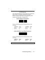
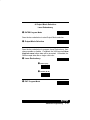
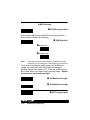
❖ IBM PC Interface
Scan one of the following “Plug and Play” bar codes to
program the 3400 for IBM AT, PS/2, or XT compatibles.
IBM PC AT and Compatibles Interface
(also PS/2 30-286, 50, 55SX, 60, 70, 70-061, 70-121, 80)
IBM PS/2 and Compatibles Interface
(for PS/2 25, 30 models)
IBM PC XT and Compatibles Interface
Each bar code above also programs a carriage return (CR) suffix.
These Plug and Play codes do not apply to 3400–X3 units.
Quick Start Programming
2–5
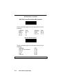
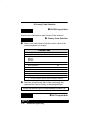
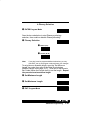
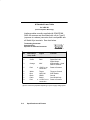
❖ IBM 4683 Ports 5B, 9B, and 17 Interface
Scan one of the following “Plug and Play” bar codes to
program the 3400 for IBM 4683 Port 5B, 9B, or 17.
IBM 4683 Port 5B Interface
IBM 4683 Port 9B HHBCR–1
IBM 4683 Port 9B HHBCR–2
IBM 4683 Port 17 Interface
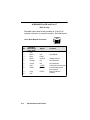
Each bar code above also programs the following suffixes for
each symbology:
symbology
suffix
symbology
suffix
EAN 8
EAN 13
UPC A
UPC E
0C
16
0D
0A
Code 39
I 2 of 5
Code 128
00 0A 0B
00 0D 0B
00 18 0B
These Plug and Play codes do not apply to 3400–X2, 3400–X3, or
3400–18 units.
2–6
Quick Start Programming
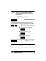
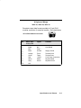
❖ OCIA Interface
Scan one of the following “Plug and Play” bar codes (this
page and the next page) to program the 3400 for
Spectra–Physics, NCR Short Format (Eight Bit), NCR
Long Format (Nine Bit), or Nixdorf OCIA.
Spectra–Physics OCIA Interface
This bar code also programs the following prefixes for each
symbology:
symbology
prefix
symbology
prefix
EAN 8
EAN 13
06 06
06
UPC A
UPC E
01
05
NCR OCIA Short Format (Eight Bit) Interface
This bar code also programs the following prefixes for each
symbology:
symbology
prefix
symbology
prefix
EAN 8
EAN 13
0F 0F
0F
UPC A
UPC E
0A
0E
These Plug and Play codes do not apply to 3400–X3 or 3400–18 units.
Quick Start Programming
2–7
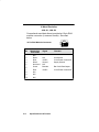
OCIA Interface, continued
NCR OCIA Long Format (Nine Bit) Interface
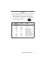
This bar code also programs the following prefixes for each
symbology:
symbology
prefix
symbology
prefix
EAN 8
EAN 13
UPC A
UPC E
46 46
46
41
45
Code 39
I 2 of 5
Code 128
42 31
42 32
42 33
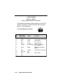
Nixdorf OCIA Interface
This bar code also programs the following prefixes for each
symbology:
symbology
prefix
EAN/ UPC with Addenda
Code 39
I 2 of 5
2 of 5
Code 128
44
44
44
44
44
4B
49
48
47
4A
These Plug and Play codes do not apply to 3400–X3 or 3400–18 units.
2–8
Quick Start Programming
❖ OCR, RS–232, and Wand Emulation Interface
Scan one of the following “Plug and Play” bar codes (this
page and the next page) to program the 3400 for Fujitsu,
IBM Port 21 OCR, RS–232, or Wand Emulation (Code 39
Format).
Fujitsu OCR Interface
This bar code also programs the following suffixes for each
symbology:
symbology
suffix
EAN 8
EAN 13
I 2 of 5
17
UPC A
17
UPC E
03 (Application Dependent)
symbology
suffix
17
17
IBM OCR (Port 21) Interface
This bar code also programs the following suffixes for each
symbology:
symbology
suffix
symbology
suffix
EAN 8
EAN 13
Code 128
0C
16
1D
UPC A
UPC E
0D
0A
These Plug and Play codes do not apply to 3400–X3 or 3400–18 units.
Quick Start Programming
2–9
OCR, RS–232, and Wand Emulation Interface, continued
RS–232 Interface
This bar code also programs the following parameters:
programmable option
setting
Baud Rate
Parity
Data Format
9600 bits per second
even
7 data bits, parity bit, 1 stop bit
(8 Bit Data)
Wand Emulation (Code 39 Format) Interface
Wand Emulation (Same Code Format) Interface [
[ Supports Code 39, UPC, EAN, Code 128, Interleaved 2 of 5, and Codabar.
All other codes output as Code 39.
These bar codes also program the following parameters:
programmable option
setting
Transmission Rate
Output Polarity
20 inches per second
Black High
Wand Emulation Plug and Play codes apply to 3400–X1 and 3400–X2
units only.
2–10
Quick Start Programming
If you’ve already programmed the 3400 using “Plug and Play”
(Section 2.2), you don’t need to continue programming the 3400.
2.3 Terminal Selection Programming
Use this section to program the 3400 to work with any
supported terminal or computer.
❖ Programming Instructions
To program the SCANTEAM 3400 using the Terminal
Selection menu:
➊ Locate the two–digit terminal I.D. number for your terminal
or computer on the Supported Terminals chart (page
2–14).
➋
Scan the “Program Terminal Interface” bar code found on
the Terminal Selection menu (page 2–14).
Quick Start Programming
2–11
➌
Scan the bar code representing the first digit of the
terminal I.D. number (also on page 2–14).
➍
Scan the bar code representing the second digit of the
terminal I.D. number.
2–12
Quick Start Programming
➎
The 3400 terminal interface is now set up. To program
a carriage return (CR) suffix see page 2–18. You may
also turn off the carriage return (or any other suffix)
using Clear Bar Code Suffix, also on page 2–18.
Terminal Selection Programming Example
You want to connect the SCANTEAM 3400 to an Esprit
terminal, model 400. The Supported Terminals Chart
(next page) lists a terminal I.D. number of “03” for the
Esprit 400 terminal.
First, scan “Program Terminal Interface” bar code
(on page 2–14).
Then, scan the Terminal I.D. number bar codes
“0” and “3”.
The 3400 has been set up, and will transmit data to the
Esprit 400.
Quick Start Programming
2–13
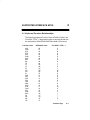
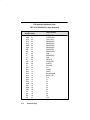
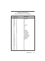
❖ Supported Terminals
Terminal
ADI
Apple Desktop Bus ADB
Bull
Burroughs
Decision Data
Model(s)
Terminal I.D.
1496
72
MAC Classic, SE SE30, II (All)
49
BDS–7 (HDS–7)
35
B25
75
DDC3596, 3597
30
DEC*
DEC
VT–220, 320, 330, 340 420
VT 510/520/525 LK411 Keyboard
(DEC Style)
VT 510/520 PC Style Keyboard
200, 400
5220
PC
700/44, 700/92, 700/94,
700/96, 700/98
DEC
Esprit
Falco
Heath Zenith
HP
04
A4
05
05
47
90
20
HP
HP
IBM
IBM
IBM
700/60
Vectra QS–16
PC XT
PS/2 25, 30
AT, PS/2 30–286, 50, 55SX,
60, 70, 70–061, 70–121, 80
79
03
01**
02**
03**
IBM
IBM 102 Key
4683, 4684
3151, 3161, 3162, 3163, 3191,
3192, 3196, 3197, 3471, 3472,
3476, 3477
3179–1, 3191, 3192, 3471,
3472, 3194
3196, 3197, 3476, 3477,
3486, 3488, 3482
3180
750
51
06
IBM 122 Key
IBM 122 Key
IBM 122 Key
IBM Thinkpad
ICL
IDEAS
ITT
Lee Data
Link
Mac
300
9271
IIS
MC–5
07
08
24
97
77
08
07
07
18
49
* Only supported by 3400–X3 units.
** The 3400–18 only supports IBM PC XT, PS2/2 25, 30, AT, PS/2 30–286, 50,
and 55SX.
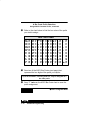
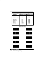
❖ Terminal Selection Menu
Scan the bar code below to program a terminal interface.
2–14
Quick Start Programming
Scan the two–digit terminal I.D. number for the terminal
interface you want set up (see chart on page 2–14).
0✽
1
2
3✽
4
5
6
7
8
9
A
B
C
D
E
F
Quick Start Programming
2–15
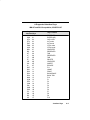
Supported Terminals, continued
Terminal
Model(s)
OCIA
OCR
Olivetti
Olivetti
Qume ANSI
M19, M24, M28, M200
240, 250, 290, 380, P500
QVT 61, 62, 70, 191, 321, 322
Terminal I.D.
52
53
01**
03**
82
Qume ASCII
Qume Enhanced PC
RS232 True
RS232 TTL
Serial Wedge*
QVT 31, 51, 61, 62, 70, 191
QVT 61, 62, 70, 82, 191, Qx15
74
38
00
00**
50
Siemens 9758
Stratus
Televideo
Telex 88 Key
(German Only)
V103
955, 965
078A, 078, 79, 80, 191, 196,
1191, 1192, 1471, 1472, 1476
078A, 078, 79, 80, 191, 196,
1191, 1192, 1471, 1472, 1476
34
14
36
25
078A, 078, 79, 80, 191, 196,
1191, 1192, 1471, 1472, 1476
46
Telex 102 Key
Telex 122 Key
45
Wand Emulation
WYSE
WYSE
WYSE ANSI[
WY–30
WY–85/185
WY 60, 120, 150, 160
61
13
16
15
WYSE ASCII[
WYSE Enhanced PC[
WY 60, 120, 150, 160, 99GT
WY 60, 120, 150, 160
14
18
* Only supported by 3400–X3 units.
** The 3400–18 only supports Olivetti M19, M24, M28, M200, Olivetti 240, 250,
290, 380, P500, and RS232 TTL.
[ Wyse 60 requires a 40 millisecond intercharacter delay. Refer to Intercharacter Delay on page 3–26 : Scan Enter, Intercharacter Delay
Selection, 0, 8 (x5ms), and Exit.
❖ Terminal Selection Menu
Scan the bar code below to program a terminal interface.
2–16
Quick Start Programming
Scan the two–digit terminal I.D. number for the terminal
interface you want set up (see chart on page 2–16).
0✽
1
2
3✽
4
5
6
7
8
9
A
B
C
D
E
F
Quick Start Programming
2–17
2.4 Program Carriage Return (CR) Suffix
If your application requires a carriage return (CR) suffix,
scan the bar code below to Program a Carriage Return
for all enabled bar code symbologies.
Caution: Scanning this code clears all previously programmed prefixes
and suffixes.
2.5 Clear Bar Code Suffix
If your application doesn’t need a bar code suffix (such as
carriage return – CR), you may scan the bar code below to
clear Bar Code Suffix.
2.6 Reset Factory Settings
Scan the bar code below to reset the SCANTEAM 3400
scanner to the factory settings. The factory settings are
indicated by “✽” (asterisks) on the programming menu
pages (Chapter 3).
2–18
Quick Start Programming
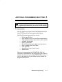
ADDITIONAL PROGRAMMING SELECTIONS
3
If you’ve already programmed the 3400 using “Plug and Play”
or Terminal Selection (Chapter 2), you don’t need to continue
programming the 3400 (unless you need to set other features).
3.1 Introduction
Use this chapter to program the SCANTEAM 3400 Hand
Held CCD Scanner for any programmable feature.
Additional programming selections include:
•
Prefixes and Suffixes
•
Dual Interface (set up for two different applications)
•
Output (beeper, delays, output mode, country codes)
•
Industrial Symbologies
•
Retail Symbologies
•
RS–232 (baud rate, parity, data format, protocols)
•
Data Formatter (Bar Code Editor)
•
CCD Operation
•
Wand Emulation and Laser Output
•
Status Check.
After you’ve programmed the SCANTEAM 3400, the
information represented by the programming bar codes is
stored in the scanner’s nonvolatile (EEPROM) memory. If
you turn the scanner off, nonvolatile memory retains the
programmed features.
Additional Programming
3–1
❖ Programming Instructions
Resetting Default Settings
The first page of each programming section allows you to
program the SCANTEAM 3400 to factory settings for that
particular section. This is useful if you’ve changed the
features (or don’t know what’s been programmed) and
want to reset the 3400 defaults, but not all its defaults.
To reset the 3400 to factory settings for a particular
programming section, turn to that section and:
➊
Scan the “ENTER” bar code to enter programming
mode.
➋
Scan the “DEFAULT” bar code to set factory settings.
Factory settings are indicated by “✽” (asterisks).
➌
Scan the “EXIT” bar code to exit programming mode.
Changing Settings
To change the default values, turn to the programming
selection you want to change:
➊
Scan the “ENTER” bar code to enter programming
mode (unless noted otherwise).
➋
Scan the Selection bar code (the bar codes toward
outside edge of page).
➌
Scan the option bar code (centered on page) to make
your programming choice, then scan “EXIT.”
Programming sequence is numbered (➊, ➋, ➌, etc.) next to bar
code, bar code title, or text describing bar code.
3–2
Additional Programming
❖ Global Programming Bar Codes
After you’ve scanned ENTER in any programming section,
you may use the bar codes below to:
DEFAULT
DEFAULT resets the scanner to factory settings.
ESCAPE
ESCAPE stops the programming sequence (programming
selections are unchanged).
EXIT
EXIT stops the programming sequence (any changed
programming selections are saved).
Additional Programming
3–3
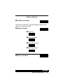
3.2 Bar Code Prefix and Suffix Programming
Use this section to program the 3400 for Bar Code Prefix
and Suffix selections. Scan the bar codes below to
default the 3400 to factory settings (✽) for bar code prefix
and suffix selections.
3–4
➊
ENTER Prefix/Suffix Program Mode
➋
DEFAULT All Prefix/Suffix Selections
➌
EXIT Prefix/Suffix Program Mode
Additional Programming
❖ Bar Code Prefix Selection:
Code I.D. Transmit
➊
ENTER Program Mode
Scan the bar code below to program Code I.D. Transmit, then
choose enable or disable.
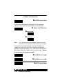
➋ Code I.D. Transmit
➍
➌
Enable (Yes)
➌
Disable (No ✽)
EXIT Program Mode
Code I.D. Chart
!" !# $
Additional Programming
3–5
❖ Bar Code Prefix Selection:
AIM I.D. Transmit
➊
ENTER Program Mode
Scan the bar code below to program AIM I.D. Transmit, then
choose enable or disable.
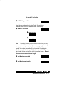
➋ AIM I.D. Transmit
➌
Enable (Yes)
➌
Disable (No ✽)
➍
EXIT Program Mode
AIM I.D. Chart
3–6
!" !# $
Additional Programming
Bar Code Prefix Example
To program a line feed prefix for UPC–A symbology only,
scan the following bar codes:
➊ ENTER (Prefix Selection)
➋ Assign ASCII Character Prefix
➌ 6, 3 (on Symbology Bar Code chart)
➍ 0, A (on ASCII Bar Code chart)
➎ F, F (on ASCII Bar Code chart)
➏ EXIT (Prefix Selection)
Where the:
“ENTER (Prefix Selection)” bar code enters programming mode.
“Assign ASCII Character Prefix” bar code starts assigning an ASCII
character prefix.
“6” and “3” bar codes specify UPC symbology (see Symbology Chart).
“0” and “A” bar codes specify Line Feed (see Hex– ASCII Chart).
“F” and “F” bar codes save the prefix assignment.
“EXIT (Prefix Selection)” bar code exits programming mode.
Bar Code Suffix Example
To program a carriage return suffix for ALL symbologies,
scan the following bar codes:
➊ ENTER (Suffix Selection)
➋ Assign ASCII Character Suffix
➌ 9, 9 (on Symbology Bar Code chart)
➍ 0, D (on ASCII Bar Code chart)
➎ F, F (on ASCII Bar Code chart)
➏ EXIT (Suffix Selection)
Where the:
“ENTER (Suffix Selection)” bar code enters programming mode.
“Assign ASCII Character Suffix” bar code starts assigning an ASCII
character suffix.
“9” and “9” bar codes specify All symbologies (see Symbology Chart).
“0” and “D” bar codes specify Carriage Return (see Hex– ASCII Chart).
“F” and “F” bar codes save the suffix assignment.
“EXIT (Suffix Selection)” bar code exits programming mode.
Additional Programming
3–7
❖ Bar Code Prefix Selection:
Assign ASCII Character Prefix
➊
ENTER Program Mode
Scan the bar code below to start assigning an ASCII
character prefix.
➋ Assign ASCII Character Prefix
➌ Refer to the chart below, then scan the two bar codes on
the next page that represent the bar code symbology
requiring a prefix.
Symbology Chart
3–8
#$
# # # # "&$ ( # &$) # %%*
# # *!# #%
$)') $#$!!" Additional Programming
1
2
3
4
5
6
7
8
9
A
B
C
D
E
Additional Programming
3–9
❖ Bar Code Prefix Selection:
Assign ASCII Character Prefix, continued
➍ Refer to the chart below to find the hex value of the prefix
you wish to assign.
Hex – ASCII Chart
NUL
SOH
STX
ETX
EOT
ENQ
ACK
BEL
BS
HT
LF
VT
FF
CR
SO
SI
00
01
02
03
04
05
06
07
08
09
0A
0B
0C
0D
0E
0F
DLE
DC1
DC2
DC3
DC4
NAK
SYN
ETB
CAN
EM
SUB
ESC
FS
GS
RS
US
10
11
12
13
14
15
16
17
18
19
1A
1B
1C
1D
1E
1F
SP
!
"
#
$
%
&
'
(
)
*
+
,
.
/
20
21
22
23
24
25
26
27
28
29
2A
2B
2C
2D
2E
2F
0
1
2
3
4
5
6
7
8
9
:
;
<
=
>
?
30
31
32
33
34
35
36
37
38
39
3A
3B
3C
3D
3E
3F
@
A
B
C
D
E
F
G
H
I
J
K
L
M
N
O
40
41
42
43
44
45
46
47
48
49
4A
4B
4C
4D
4E
4F
P 50
Q 51
R 52
S 53
T 54
U 55
V 56
W 57
X 58
Y 59
Z 5A
[ 5B
\ 5C
] 5D
^ 5E
_ 5F
`
a
b
c
d
e
f
g
h
i
j
k
l
m
n
o
60
61
62
63
64
65
66
67
68
69
6A
6B
6C
6D
6E
6F
p
70
q
71
r
72
s
73
t
74
u
75
v
76
w 77
x
78
y
79
z
7A
{
7B
|
7C
}
7D
~ 7E
DEL 7F
➎ Scan two of the ASCII Bar Codes (next page) that
represent the hex digits of the prefix you require.
Up to 20 characters, including Code I.D., may be assigned as a
bar code prefix.
➏ Scan “F” twice on the ASCII Bar Code chart to save the
prefix assignment.
➐
3–10
Additional Programming
EXIT Program Mode
0 ✽✽
1
2
3
4
5
6
7
8
9
A
B
C
D
E
F
Additional Programming
3–11
❖ Bar Code Suffix Selection:
Assign ASCII Character Suffix
➊
ENTER Program Mode
Scan the bar code below to start assigning an ASCII
character suffix.
➋ Assign ASCII Character Suffix
➌ Refer to the chart below, then scan the two bar codes on
the next page that represent the bar code symbology
requiring a suffix.
Symbology Chart
3–12
!
#!$ #!% ""&
$!" Additional Programming
1
2
3
4
5
6
7
8
9
A
B
C
D
E
Additional Programming
3–13
❖ Bar Code Suffix Selection:
Assign ASCII Character Suffix, continued
➍ Refer to the chart below to find the hex value of the suffix
you wish to assign.
Hex – ASCII Chart
NUL
SOH
STX
ETX
EOT
ENQ
ACK
BEL
BS
HT
LF
VT
FF
CR
SO
SI
00
01
02
03
04
05
06
07
08
09
0A
0B
0C
0D
0E
0F
DLE
DC1
DC2
DC3
DC4
NAK
SYN
ETB
CAN
EM
SUB
ESC
FS
GS
RS
US
10
11
12
13
14
15
16
17
18
19
1A
1B
1C
1D
1E
1F
SP
!
"
#
$
%
&
'
(
)
*
+
,
.
/
20
21
22
23
24
25
26
27
28
29
2A
2B
2C
2D
2E
2F
0
1
2
3
4
5
6
7
8
9
:
;
<
=
>
?
30
31
32
33
34
35
36
37
38
39
3A
3B
3C
3D
3E
3F
@
A
B
C
D
E
F
G
H
I
J
K
L
M
N
O
40
41
42
43
44
45
46
47
48
49
4A
4B
4C
4D
4E
4F
P 50
Q 51
R 52
S 53
T 54
U 55
V 56
W 57
X 58
Y 59
Z 5A
[ 5B
\ 5C
] 5D
^ 5E
_ 5F
`
a
b
c
d
e
f
g
h
i
j
k
l
m
n
o
60
61
62
63
64
65
66
67
68
69
6A
6B
6C
6D
6E
6F
p
70
q
71
r
72
s
73
t
74
u
75
v
76
w 77
x
78
y
79
z
7A
{
7B
|
7C
}
7D
~ 7E
DEL 7F
➎ Scan two of the ASCII Bar Codes (next page) that
represent the hex digits of the suffix you require.
Up to 20 characters may be assigned as a bar code suffix.
➏ Scan “F” twice on the ASCII Bar Code chart to save the
suffix assignment.
➐
3–14
Additional Programming
EXIT Program Mode
0 ✽✽
1
2
3
4
5
6
7
8
9
A
B
C
D
E
F
Additional Programming
3–15
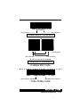
3.3 Dual Interface Programming
SCANTEAM models 3400–X1 and 3400–X2 support Dual
Interface, which allows you to connect to two different
terminals by switching interface cables. The figure below
illustrates Dual Interface.
SCANTEAM
3400
PC
Terminal
Terminal
Interface
Cable
Primary Application
SCANTEAM
3400
Portable Data Terminal
HHLC
Interface
Cable
Secondary Application
3–16
Additional Programming
Dual Interface Programming, continued
The 3400 is compatible with a wide range of terminals in
the primary (or single) interface mode. (Primary terminal
selection programming is found on page 2–11.)
Secondary interface is designed to support a limited set
of interfaces common to portable data terminals. These
interfaces include:
•
Hand Held Laser Emulation (HHLC)
•
Wand Emulation, Code 39
•
Wand Emulation, Same Code
•
RS–232 TTL.
The scanner must be programmed for secondary
interface, just as it must be for primary interface. To
program the 3400 for secondary interface, follow the
steps below. (Dual Interface single scan programming
codes on the following page.)
➊
While the scanner is connected to the primary terminal
interface, scan one of the single bar codes to enable the
secondary interface.
Note:
ENTER and EXIT bar codes are not needed for
Dual Interface.
➋
Disconnect the primary interface cable from the scanner
and attach the secondary interface cable to the scanner.
➌
Attach the secondary interface cable to the secondary
terminal and power up the terminal.
➍ Program the desired programmable selections for the
secondary interface. These selections include:
Prefix/Suffix
Reread Delay
Buffer Scans
Wand Emulation Polarity
Trigger Mode
Wand Emulation Transmission Rate
Symbology selections (including EAN ISBN).
3400–X3 and 3400–18 units do not support Dual Interface.
Additional Programming
3–17
Dual Interface Programming, continued
Dual Interface Single Scan Programming Codes
❖ Code 39 Wand Emulation Selection ✽
❖ Same Code Wand Emulation Selection [
[ ! ❖ RS–232 Selection
❖ Laser Emulation Selection
Dual Interface Programming Notes:
•
To change the secondary interface from one selection to
another (from HHLC to RS–232, for example), the
scanner must be reconnected to the primary interface,
and then reprogrammed for the new secondary
interface. Connect the scanner to the primary interface
cable. Follow steps 1–4 on page 3–17.
3400–X3 and 3400–18 units do not support Dual Interface.
3–18
Additional Programming
Dual Interface Programming, continued
•
Scanning “Plug and Play” bar codes (single scan
terminal selection bar codes – Section 2.2), or changing
the terminal type does not affect Dual Interface settings.
•
RS–232 programmable selections are used by both the
primary and secondary interfaces. Changing an
RS–232 parameter (such as baud rate or parity), while
in primary or secondary mode will affect both interfaces.
Dual Interface selection is not available if the 3400 is
programmed for an HP terminal with a Terminal I.D. of 20 or 79,
or for a WYSE terminal with a Terminal I.D. of 13–18.
Primary Interface only Selection allows you to temporarily
disable the dual interface selection, while retaining your
secondary interface setup in memory. If you want to
enable the secondary interface again, scan the Enable
Dual Interface Selection bar code.
❖ Primary Interface only Selection ✽
❖ Enable Dual Interface Selection
3400–X3 and 3400–18 units do not support Dual Interface.
Additional Programming
3–19
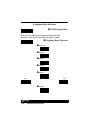
3.4 Output Programming
Use this section to program the 3400 for Output
selections. Scan the bar codes below to default the 3400
to factory settings (✽) for output selections.
3–20
➊
ENTER Output Program Mode
➋
DEFAULT All Output Selections
➌
EXIT Output Program Mode
Additional Programming
❖ Beeper Selection
➊
ENTER Program Mode
Scan the bar code below to program Beeper selection, then
choose the volume you want.
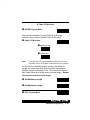
➋ Beeper Selection
➍
➌
Beeper Off
➌
Beeper Low Volume
➌
Beeper Medium Volume
➌
Beeper High Volume ✽
EXIT Program Mode
Additional Programming
3–21
❖ Keyboard Style Selection
➊
ENTER Program Mode
Scan the bar code below to program Keyboard Style
selection, then choose the keyboard style you want.
➋ Keyboard Style Selection
➌
Style A ✽
➌
Style B
➌
Style C
➌
Style D
➌
Style F
Yes
No
➌
3–22
Style G
Additional Programming
Keyboard Style Selection, continued
➌
Style H
Yes
No
➌
Style I
Yes
No
➌
Style J
Yes
➍
No
EXIT Program Mode
The charts on the following pages show the keyboard style for
supported terminals.
Note: Styles A, B, and C cannot be used with one another; however they
may be combined with other styles. All styles with Yes / No bar codes
can be scanned in combination with all other styles. For example, you
can combine style F with G. First scan F, then scan G. If Style D is
combined with another style, D must be scanned first. For example,
scan D before scanning B to enable both the CTRL ASCII and the CAPS
LOCK functions. Scanning Style A disables Style D.
Additional Programming
3–23
1
IBM XT
std
2
IBM PS/2
std
3
IBM AT
std
5
IBM AT3
DEC VT510
IBMTerminals
w/102 keys
IBMTerminals
w/122 keys
IBMTerminals
w/122 keys
Not Used*
std
6
7
8
9
std
std
std
CAPS
LOCK
CAPS
LOCK
CAPS
LOCK
CAPS
LOCK
CAPS
LOCK
SHFT
LOCK
SHFT
LOCK
SHFT
LOCK
SHFT
LOCK
SHFT
LOCK
CTRL
ASCII
CTRL
ASCII
CTRL
ASCII
CTRL
ASCII
No
CAPS
LOCK
CAPS
LOCK
SHFT
LOCK
SHFT
LOCK
std
No
No
Yes
No
No
Yes
Yes
Yes
12/9
Yes
Yes
Yes
Yes
14/3
Yes
Yes
Yes
Yes 14/11
Yes
No
Yes
Yes
No
No
No
No
Yes
Yes
No
No
No
No
Yes
Yes
No
No
No
No
No
No
10 Not Used*
std
D/E
No
No
No
No
11 Not Used*
std
D/E
No
No
No
No
19 Not Used*
std
D/E
No
No
No
No
23
std
No
No
No
No
24
std
D/E
No
No
No
No
25
std
D/E
No
No
No
No
35
std
No
No
No
No
45
std
No
No
No
No
46
std
No
No
No
No
71
std
No
No
No
No
84
std
CAPS
LOCK
CAPS
LOCK
CAPS
LOCK
CAPS
LOCK
CAPS
LOCK
No
No
No
No
97 IBM
Thinkpad
std
obĆ
obĆ
solete solete
CTRL
ASCII
No
N/A
A4 DEC VT510
LK411
std
CAPS SHFT
LOCK LOCK
CTRL
ASCII
SHFT
LOCK
SHFT
LOCK
SHFT
LOCK
SHFT
LOCK
SHFT
LOCK
* Unused in SCANTEAM 3400 (IDs 9, 10, 11, 19)
3–24
Additional Programming
obĆ
obĆ
solete solete
Yes
Yes
Yes
Yes 14/11
Yes
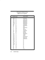
The Keyboard Style Table below applies to
SCANTEAM 3400 software prior to software
revision level 4.0.
Keyboard Style
Note:
(If terminal is not listed, then no secondary type keyboard is supported.)
IBM PC/XT
IBM PC/AT
XT
CAPS LOCK
SHIFT LOCK CTRL" + ASCII [ Gr DOS SHIFT LOCK
AT
CAPS LOCK
SHIFT LOCK CTRL" + ASCII [ Gr DOS SHIFT LOCK
NORM
CAPS LOCK
SHIFT LOCK CTRL" + ASCII [ Gr DOS SHIFT LOCK
HDS 2000, 3200
T/W
CTRL +"
IBM 3180 (122 Key)
T/W
D/E
COMTERM 6178
T/W
D/E
TELEX (88 Key)
T/W
D/E
SIEMENS 9758
NORM
CAPS LOCK
NCR 7052
34Key
56 Key
IBM PS2 (50-80)
122 Key Caps On 122 Key Caps Off
[ ASCII function codes (00-1F) are sent to the terminal via a CTRL+" sequence
(i.e., `CR'=CTRL+M)
❖ Keyboard Emulation Mode
(For IBM PC/AT – terminal ID = 03 – only)
➊
ENTER Program Mode
Scan the bar codes below to program Keyboard Emulation
Mode, then enable or disable the selection.
➋ Keyboard Emulation Selection
➌
➍
➎
Enable
Keyboard Emulation Mode
➍
Disable
EXIT Program Mode
Additional Programming
3–25
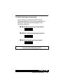
❖ Programmable Output Delay Selections
➊
ENTER Program Mode
Scan the bar code below to start Intercharacter Delay
selection.
➋ Intercharacter Delay Selection
➌ Scan two of the Numeric Bar Codes (next page) to set the
delay to any value between 00 ✽ and 99[.
Scan the bar code below to start Interfunction Delay selection.
➋ Interfunction Delay Selection
➌ Scan two of the Numeric Bar Codes (next page) to set the
delay to any value between 00 ✽ and 99[.
Scan the bar code below to start Intermessage Delay
selection.
➋ Intermessage Delay Selection
➌ Scan two of the Numeric Bar Codes (next page) to set the
delay to any value between 00 ✽ and 99[.
➍
[ x5ms
3–26
Additional Programming
EXIT Program Mode
0 ✽✽
1
2
3
4
5
6
7
8
9
Programmable Output Delay Example
The SCANTEAM 3400 is programmed as follows:
➊ Intercharacter Delay = 10ms
➋ Interfunction Delay = 50ms
➌ Bar Code Suffix = Tab and Carriage Return
When a bar code symbol containing the characters “123” is scanned,
the 3400 will output the following to the terminal / computer:
1
2
10ms
delay
3
10ms
delay
Tab
10ms
delay
Carriage Return
50ms
delay
Additional Programming
3–27
❖ Output Mode Selection:
Buffer Scans
➊
ENTER Program Mode
Scan the bar code below to start Output Mode selection.
➋ Output Mode Selection
Scan the bar code below to program Buffer Scans, then
choose enable or disable. If enabled, the 3400 accepts a
second scan while transmitting the current scan to the
terminal. If disabled, the 3400 won’t accept additional scans
until the current scan is output to the terminal.
➌ Buffer Scans
➍
Enable (Yes ✽)
➍
Disable (No)
Programming the 3400 for Wand Emulation mode disables the
Buffer Scans Output option.
➎
3–28
Additional Programming
EXIT Program Mode
❖ Output Mode Selection:
Function Code Transmit
➊
ENTER Program Mode
Scan the bar code below to start Output Mode selection.
➋ Output Mode Selection
Scan the bar code below to program Function Code Transmit,
then choose enable or disable. Refer to Chapter 4 for
Function Code tables (Supported Interface Keys).
➌ Function Code Transmit
➎
➍
Enable (Yes ✽)
➍
Disable (No)
EXIT Program Mode
Additional Programming
3–29
Output Mode Selection, continued
Function Code Transmit Enabled Example
The SCANTEAM 3400 is connected to an IBM PC XT
and is programmed as follows:
➊ Bar Code Prefix: GS (1D) – F10 key
➋ Bar Code Suffix: CR (0D) – ENTER key
➌ Function Code Transmit: Enabled
When a bar code containing the characters “1234<HT>5678” is
scanned, the 3400 will output the following to the terminal / computer:
F10
1
2
3
4 Tab 5
6
7
8
bar code
prefix
ENTER
bar code
suffix
The Supported Interface Key “HT” (IBM XT table page 4–4) has
been translated and sent as the Tab key.
Function Code Transmit Disabled Example
The SCANTEAM 3400 is connected to an IBM PC XT
and is programmed as follows:
➊ Bar Code Prefix: GS (1D) – F10 key
➋ Bar Code Suffix: CR (0D) – ENTER key
➌ Function Code Transmit: Disabled
When a bar code containing the characters “1234<HT>5678” is
scanned, the 3400 will output the following to the terminal / computer:
F10
1
2
3
4
bar code
prefix
5
6
7
8
ENTER
bar code
suffix
The “HT” has been stripped from the data string. (The prefix
and suffix are not affected by Function Code Transmit.)
3–30
Additional Programming
❖ Output Mode Selection:
Laser Redundancy
➊
ENTER Program Mode
Scan the bar code below to start Output Mode selection.
➋ Output Mode Selection
Scan the bar code below to program Laser Redundancy, then
choose enable or disable. If enabled, the 3400 requires three
identical scans before data will be accepted. If disabled, the
3400 accepts data after a single valid scan.
➌ Laser Redundancy
➎
➍
Enable (Yes)
➍
Disable (No ✽)
EXIT Program Mode
Additional Programming
3–31
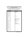
❖ Country Code Selection
➊
ENTER Program Mode
Scan the bar code below to start Country Code selection.
➋ Country Code Selection
➌ Refer to the chart below to find the numeric value of the
country keyboard you require.
Country Code
%!) ))(
# !*$
%$'" [
!%#%
&'+, [
+%
'%
'$%,*()'!
)#,
+!)-'#%
%!) !% &$
%$'" &'+, [
✽
Use special Wyse selection when using Wyse terminals.
➍ Scan two of the Numeric Bar Codes (next page) that
represent the Country Code you want programmed.
Country Code Selection applies to Keyboard Wedge interfaces only.
➎
3–32
Additional Programming
EXIT Program Mode
0 ✽✽
1
2
3
4
5
6
7
8
9
Additional Programming
3–33
Note:
The NCR 7052 Keypad Selection applies to
SCANTEAM 3400 software prior to software
revision level 4.0.
❖ NCR 7052 Keypad Selection*
➊
ENTER Program Mode
Scan the bar code below to program NCR 7052 Keyboard
Layout selection, then choose the keyboard layout you want.
➋ NCR 7052 Keypad Selection
➌
Layout 1 (telephone style keypad) ✽
➌
Layout 2 (calculator style keypad)
➌
Layout 3 (PC/AT style keypad)
➍
EXIT Program Mode
* 3400–X3 units do not support NCR 7052 Keypad
Selection.
3–34
Additional Programming
3.5 Industrial Symbology Programming
Use this section to program the 3400 for Industrial
Symbology selections. Scan the bar codes below to
default the 3400 to factory settings (✽) for industrial
symbology selections.
➊
ENTER Industrial Symbology Program Mode
➋
DEFAULT All Industrial Symbology Selections
➌
EXIT Industrial Symbology Program Mode
Examples of Industrial bar codes may be found on page 3–39 in
this programming section.
Additional Programming
3–35
❖ Codabar Selection
➊
ENTER Program Mode
Scan the bar code below to start Codabar symbology
selection, then enable or disable Codabar decoding.
➋ Codabar Selection
Note:
➌
Enable (Yes ✽)
➌
Disable (No)
If you don’t need to program additional selections, you may
scan EXIT now to exit program mode and save your changes.
To set minimum allowable length, scan the “Set Minimum
Length” bar code, then refer to the Industrial Symbologies
Min/Max Length chart (page 3–52). Scan two of the Numeric
Bar Codes (below the Length chart) to set the length. Repeat
the process to set maximum length.
➍ Set Minimum Length
➍ Set Maximum Length
Other Codabar selections include: Start/Stop Transmit,
Check Character Required, Check Character Transmit,
Concatenation, and Concatenation Required.
3–36
Additional Programming
Codabar Selection, continued
Scan the bar code below to program Codabar Start/Stop
Transmit, then choose enable or disable.
➍ Start/Stop Transmit
➎
Enable (Yes)
➎
Disable (No ✽)
Scan the bar code below to program Codabar Check
Character Required, then choose enable or disable.
➍ Check Character Required
➎ Enable (Yes)
➎
Disable (No ✽)
Scan the bar code below to program Codabar Check
Character Transmit, then choose enable or disable.
➍ Check Character Transmit
➎ Enable (Yes)
➎
Disable (No ✽)
Additional Programming
3–37
Codabar Selection, continued
Scan the bar code below to program Codabar Concatenation,
then choose enable or disable.
➍ Concatenation
➎
Enable (Yes ✽)
➎
Disable (No)
Scan the bar code below to program Codabar Concatenation
Required, then choose enable or disable.
➍ Concatenation Required
➎
Enable (Yes)
➎
Disable (No ✽)
➏
3–38
Additional Programming
EXIT Program Mode
B+12345–C
Start Character
Stop Character
Codabar without Concatenation
A12D
D34A
Concatenation
Start Character
Stop Character
❖ Scan would look like: A1234A
Codabar with Concatenation
Codabar Bar Code
*TEST–SHEET*
Start Character
Stop Character
Code 39 Bar Code
Additional Programming
3–39
❖ Code 39 Selection
➊
ENTER Program Mode
Scan the bar code below to start Code 39 symbology
selection, then enable or disable Code 39 decoding.
➋ Code 39 Selection
Note:
➌
Enable (Yes ✽)
➌
Disable (No)
If you don’t need to program additional selections, you may
scan EXIT now to exit program mode and save your changes.
To set minimum allowable length, scan the “Set Minimum
Length” bar code, then refer to the Industrial Symbologies
Min/Max Length chart (page 3–52). Scan two of the Numeric
Bar Codes (below the Length chart) to set the length. Repeat
the process to set maximum length.
➍ Set Minimum Length
➍ Set Maximum Length
Other Code 39 selections include: Start/Stop Transmit,
Check Character Required, Check Character Transmit, Full
ASCII, and Append Option.
3–40
Additional Programming
Code 39 Selection, continued
Scan the bar code below to program Code 39 Start/Stop
Transmit, then choose enable or disable.
➍ Start/Stop Transmit
➎ Enable (Yes)
➎
Disable (No ✽)
Scan the bar code below to program Code 39 Check
Character Required, then choose enable or disable.
➍ Check Character Required
➎
Enable (Yes)
➎
Disable (No ✽)
Scan the bar code below to program Code 39 Check
Character Transmit, then choose enable or disable.
➍ Check Character Transmit
➎ Enable (Yes)
➎
Disable (No ✽)
Additional Programming
3–41
Code 39 Selection, continued
Scan the bar code below to program Code 39 Full ASCII, then
choose enable or disable.
➍ Full ASCII
➎
Enable (Yes ✽)
➎
Disable (No)
Scan the bar code below to program Code 39 Append Option,
then choose enable or disable.
➍ Append Option
➎
Enable (Yes)
➎
Disable (No ✽)
➏
3–42
Additional Programming
EXIT Program Mode
❖ Interleaved 2 of 5 Selection
➊
ENTER Program Mode
Scan the bar code below to start Interleaved 2 of 5 symbology
selection, then enable or disable Interleaved 2 of 5 decoding.
➋ Interleaved 2 of 5 Selection
Note:
➌
Enable (Yes ✽)
➌
Disable (No)
If you don’t need to program additional selections, you may
scan EXIT now to exit program mode and save your changes.
To set minimum allowable length, scan the “Set Minimum
Length” bar code, then refer to the Industrial Symbologies
Min/Max Length chart (page 3–52). Scan two of the Numeric
Bar Codes (below the Length chart) to set the length. Repeat
the process to set maximum length.
➍ Set Minimum Length
➍ Set Maximum Length
Other Interleaved 2 of 5 selections include: Check Digit
Required and Check Digit Transmit.
Additional Programming
3–43
Interleaved 2 of 5 Selection, continued
Scan the bar code below to program Interleaved 2 of 5 Check
Digit Required, then choose enable or disable.
➍ Check Digit Required
➎
Enable (Yes)
➎
Disable (No ✽)
Scan the bar code below to program Interleaved 2 of 5 Check
Digit Transmit, then choose enable or disable.
➍ Check Digit Transmit
➎
Enable (Yes)
➎
Disable (No ✽)
➏
3–44
Additional Programming
EXIT Program Mode
❖ Code 2 of 5 Selection
➊
ENTER Program Mode
Scan the bar code below to start Code 2 of 5 symbology
selection, then enable or disable Code 2 of 5 decoding.
➋ Code 2 of 5 Selection
Note:
➌
Enable (Yes ✽)
➌
Disable (No)
If you don’t need to program additional selections, you may
scan EXIT now to exit program mode and save your changes.
To set minimum allowable length, scan the “Set Minimum
Length” bar code, then refer to the Industrial Symbologies
Min/Max Length chart (page 3–52). Scan two of the Numeric
Bar Codes (below the Length chart) to set the length. Repeat
the process to set maximum length.
➍ Set Minimum Length
➍ Set Maximum Length
➎
EXIT Program Mode
Additional Programming
3–45
❖ Matrix 2 of 5 Selection
➊
ENTER Program Mode
Scan the bar code below to start Matrix 2 of 5 symbology
selection, then enable or disable Matrix 2 of 5 decoding.
➋ Matrix 2 of 5 Selection
Note:
➌
Enable (Yes ✽)
➌
Disable (No)
If you don’t need to program additional selections, you may
scan EXIT now to exit program mode and save your changes.
To set minimum allowable length, scan the “Set Minimum
Length” bar code, then refer to the Industrial Symbologies
Min/Max Length chart (page 3–52). Scan two of the Numeric
Bar Codes (below the Length chart) to set the length. Repeat
the process to set maximum length.
➍ Set Minimum Length
➍ Set Maximum Length
➎
3–46
Additional Programming
EXIT Program Mode
❖ Code 11 Selection
➊
ENTER Program Mode
Scan the bar code below to start Code 11 symbology
selection, then enable or disable Code 11 decoding.
➋ Code 11 Selection
Note:
➌
Enable (Yes ✽)
➌
Disable (No)
If you don’t need to program additional selections, you may
scan EXIT now to exit program mode and save your changes.
To set minimum allowable length, scan the “Set Minimum
Length” bar code, then refer to the Industrial Symbologies
Min/Max Length chart (page 3–52). Scan two of the Numeric
Bar Codes (below the Length chart) to set the length. Repeat
the process to set maximum length.
➍ Set Minimum Length
➍ Set Maximum Length
Additional Programming
3–47
Code 11 Selection, continued
Scan the bar code below to program 2 Check Digits Required
for Code 11, then choose enable or disable.
➍ 2 Check Digits Required
➎
Enable (Yes ✽)
➎
Disable (No [)
[ ➏
3–48
Additional Programming
EXIT Program Mode
❖ Code 93 Selection
➊
ENTER Program Mode
Scan the bar code below to start Code 93 symbology
selection, then enable or disable Code 93 decoding.
➋ Code 93 Selection
Note:
➌
Enable (Yes ✽)
➌
Disable (No)
If you don’t need to program additional selections, you may
scan EXIT now to exit program mode and save your changes.
To set minimum allowable length, scan the “Set Minimum
Length” bar code, then refer to the Industrial Symbologies
Min/Max Length chart (page 3–52). Scan two of the Numeric
Bar Codes (below the Length chart) to set the length. Repeat
the process to set maximum length.
➍ Set Minimum Length
➍ Set Maximum Length
➎
EXIT Program Mode
Additional Programming
3–49
❖ Code 128 Selection
➊
ENTER Program Mode
Scan the bar code below to start Code 128 symbology
selection, then enable or disable Code 128 decoding.
➋ Code 128 Selection
Note:
➌
Enable (Yes ✽)
➌
Disable (No)
If you don’t need to program additional selections, you may
scan EXIT now to exit program mode and save your changes.
To set minimum allowable length, scan the “Set Minimum
Length” bar code, then refer to the Industrial Symbologies
Min/Max Length chart (page 3–52). Scan two of the Numeric
Bar Codes (below the Length chart) to set the length. Repeat
the process to set maximum length.
➌ Set Minimum Length
➌ Set Maximum Length
3–50
Additional Programming
Code 128 Selection, continued
EAN–128 Programming
When enabled, the 3400 substitutes a <GS> for Function
Character 1.
➍ <GS> Substitution
➎
Enable (Yes ✽)
➎ Disable (No)
Note:
➏
For complete EAN-128 support, the AIM code ID
feature also should be enabled. Refer to Page 3–6.
EXIT Program Mode
❖ Disable All Symbologies
➊
ENTER Program Mode
Scan the bar code below to Disable ALL Symbologies.
Caution:
You will not be prompted to verify this option.
➋ Disable All Symbologies
➌
EXIT Program Mode
Note:
All Retail Symbologies will be disabled also.
Additional Programming
3–51
Industrial Symbologies Min/Max Length Chart
" # ✽
✽
[
[
[
[
✽
✽
✽
✽
✽
✽
✽
✽
✽
✽
[ ! ! $ 3–52
0
1
2
3
4
5
6
7
8
9
Additional Programming
3.6 Retail Symbology Programming
Use this section to program the 3400 for Retail
Symbology selections. Scan the bar codes below to
default the 3400 to factory settings (✽) for retail
symbology selections.
➊
ENTER Retail Symbology Program Mode
➋
DEFAULT All Retail Symbology Selections
➌
EXIT Retail Symbology Program Mode
Examples of Retail bar codes may be found on pages 3–57, 3–61,
and 3–62 in this programming section.
Additional Programming
3–53
❖ UPC Selection
➊
ENTER Program Mode
Scan the bar code below to start UPC symbology selection.
➋ UPC Selection
UPC selections include: Version A, Version E0, Version
E1, Check Digit Transmit, Number System Transmit, Version
E Expand, 2–Digit Addendum, and 5–Digit Addendum.
Scan the bar code below to program UPC Version A, then
choose enable or disable.
➌ Version A
➍
Enable (Yes ✽)
➍
Disable (No)
Scan the bar code below to program UPC Version E0, then
choose enable or disable.
➌ Version E0
3–54
➍
Enable (Yes ✽)
➍
Disable (No)
Additional Programming
UPC Selection, continued
Scan the bar code below to program UPC Version E1, then
choose enable or disable.
➌ Version E1
Note:
➍
Enable (Yes)
➍
Disable (No ✽)
Version E1 only works if EAN 13 is disabled. Refer to
EAN 13 Page 3–58.
Scan the bar code below to program UPC Check Digit
Transmit, then choose enable or disable.
➌ Check Digit Transmit
➍ Enable (Yes ✽)
➍
Disable (No)
Scan the bar code below to program UPC Number System
Transmit, then choose enable or disable.
➌ Number System Transmit
➍ Enable (Yes ✽)
➍
Disable (No)
Additional Programming
3–55
UPC Selection, continued
Scan the bar code below to program UPC Version E Expand,
then choose enable or disable.
➌ Version E Expand
➍
Enable (Yes)
➍
Disable (No ✽)
Scan the bar code below to program UPC 2–Digit Addenda,
then choose enable or disable.
➌ 2–Digit Addenda
➍
Enable (Yes)
➍
Disable (No ✽)
Scan the bar code below to program UPC 5–Digit Addenda,
then choose enable or disable.
➌ 5–Digit Addenda
3–56
➍
Enable (Yes)
➍
Disable (No ✽)
Additional Programming
UPC Selection, continued
➎
EXIT Program Mode
12345
0 31425 60789 5
# System
Check Digit
5–Digit Addendum
UPC–A Bar Code
0 12345 00350 9
# System
Check Digit
NO Addendum
UPC–A Bar Code
Additional Programming
3–57
❖ EAN Selection
➊
ENTER Program Mode
Scan the bar code below to start EAN symbology selection.
➋ EAN Selection
EAN selections include: EAN/JAN 13, EAN/JAN 8, Check
Digit Transmit, 2–Digit Addendum, 5–Digit Addendum, and
ISBN Enable.
Scan the bar code below to program EAN/JAN 13, then
choose enable or disable.
➌ EAN/JAN 13
3–58
➍
Enable (Yes ✽)
➍
Disable (No)
Additional Programming
EAN Selection, continued
Scan the bar code below to program EAN/JAN 8, then choose
enable or disable.
➌ EAN/JAN 8
➍
Enable (Yes ✽)
➍
Disable (No)
Scan the bar code below to program EAN Check Digit
Transmit, then choose enable or disable.
➌ Check Digit Transmit
➍
Enable (Yes ✽)
➍
Disable (No)
Scan the bar code below to program EAN 2–Digit Addenda,
then choose enable or disable.
➌ 2–Digit Addenda
➍
Enable (Yes)
➍
Disable (No ✽)
Additional Programming
3–59
EAN Selection, continued
Scan the bar code below to program EAN 5–Digit Addenda,
then choose enable or disable.
➌ 5–Digit Addenda
➍
Enable (Yes)
➍
Disable (No ✽)
Scan the bar code below to program EAN ISBN Enable, then
choose enable or disable.
➌ ISBN Enable
➍
Enable (Yes)
➍
Disable (No ✽)
➎
3–60
Additional Programming
EXIT Program Mode
50595
97 80123 8
8 Digits
Check Digit
5–Digit Addendum
EAN 8 Bar Code
97 80123 8
8 Digits
Check Digit
NO Addendum
EAN 8 Bar Code
Additional Programming
3–61
50595
9 780123 456793
13 Digits
Check Digit
5–Digit Addendum
EAN 13 Bar Code
9 781853 360824
13 Digits
Check Digit
EAN 13 Bar Code
3–62
Additional Programming
NO Addendum
❖ UPC & EAN Addenda Selection
➊
ENTER Program Mode
Scan the bar code below to program UPC & EAN Addenda
Required, then choose enable or disable.
➋ UPC & EAN Addenda Required
➌
Enable (Yes)
➌
Disable (No ✽)
Scan the bar code below to program UPC/EAN Format, then
choose to add a space or not to add a space between the
UPC/EAN code and addenda.
➋ Addenda Format
➍
➌
Space (✽)
➌
No Space
EXIT Program Mode
Additional Programming
3–63
❖ MSI Selection
➊
ENTER Program Mode
Scan the bar code below to start MSI symbology selection,
then enable or disable MSI decoding.
➋ MSI Selection
Note:
➌
Enable (Yes)
➌
Disable (No ✽)
If you don’t need to program additional selections, you may
scan EXIT now to exit program mode and save your changes.
To set minimum allowable length, scan the “Set Minimum
Length” bar code, then refer to the Retail Symbologies
Min/Max Length chart (page 3–67). Scan two of the Numeric
Bar Codes (below the Length chart) to set the length. Repeat
the process to set maximum length.
➍ Set Minimum Length
➍ Set Maximum Length
➎
3–64
Additional Programming
EXIT Program Mode
❖ Plessey Selection
➊
ENTER Program Mode
Scan the bar code below to start Plessey symbology
selection, then enable or disable Plessey decoding.
➋ Plessey Selection
Note:
➌
Enable (Yes)
➌
Disable (No ✽)
If you don’t need to program additional selections, you may
scan EXIT now to exit program mode and save your changes.
To set minimum allowable length, scan the “Set Minimum
Length” bar code, then refer to the Retail Symbologies
Min/Max Length chart (page 3–67). Scan two of the Numeric
Bar Codes (below the Length chart) to set the length. Repeat
the process to set maximum length.
➍ Set Minimum Length
➍ Set Maximum Length
➎
EXIT Program Mode
Additional Programming
3–65
❖ Disable All Symbologies
➊
ENTER Program Mode
Scan the bar code below to Disable ALL Symbologies.
Caution:
You will not be prompted to verify this option.
➋ Disable All Symbologies
➌
Note:
3–66
EXIT Program Mode
All Industrial Symbologies will be disabled also.
Additional Programming
Retail Symbologies Min/Max Length Chart
✽
✽
✽
✽
0
1
2
3
4
5
6
7
8
9
Additional Programming
3–67
3.7 RS–232 Programming
Use this section to program the 3400 for RS–232
selections. Scan the bar codes below to default the 3400
to factory settings (✽) for RS–232 selections.
3–68
➊
ENTER RS–232 Program Mode
➋
DEFAULT All RS–232 Selections
➌
EXIT RS–232 Program Mode
Additional Programming
❖ Baud Rate Selection
➊
ENTER Program Mode
Scan the bar code below to program Baud Rate selection,
then choose the baud rate you want.
➋ Baud Rate Selection
➌
300 bps (bits per second)
➌
➌
600 bps (bits per second)
➌
1200 bps (bits per second)
➌
19200 bps (bits per second)
➌
2400 bps (bits per second)
➌
38400 bps (bits per second)
➍
EXIT Program Mode
➌
4800 bps (bits per second)
9600 bps (bits per second) ✽
Additional Programming
3–69
❖ Parity Selection
➊
ENTER Program Mode
Scan the bar code below to program Parity selection, then
choose the parity you want.
➋ Parity Selection
➌
None
➌
Mark
➌
Space
➌
Odd
➌
Even ✽
➍
3–70
Additional Programming
EXIT Program Mode
❖ Data Format Selection
➊
ENTER Program Mode
Scan the bar code below to program Data Format selection,
then choose the data format you want.
➋ Data Format Selection
➍
➌
7 Data, Parity, 1 Stop ✽
➌
7 Data, Parity, 2 Stop
➌
8 Data, Parity, 1 Stop
EXIT Program Mode
Additional Programming
3–71
❖ CTS Handshake Selection
➊
ENTER Program Mode
This selection allows you to disable the CTS Handshake if
your terminal/computer doesn’t have a CTS I/O line.
Scan the bar code below to program CTS Handshake
selection, then choose enable or disable.
➋ CTS Handshake Selection
➌
Enable (Yes)
➌
Disable (No ✽)
CTS Handshake only applies when the 3400 is in Serial Mode (RS–232,
TTL or True).
➍
3–72
Additional Programming
EXIT Program Mode
❖ Serial Wedge Selection
➊
ENTER Program Mode
Scan the bar code below to program Serial Wedge selection,
then choose the Operating Mode Output Direction you want.
➋ Serial Wedge Selection
(Model 3400–X3 only)
➌
To P1 ✽ [
➌
To P2 [
➌
To P1 and P2 [
[ P1 and P2 are serial wedge designations printed on the serial
wedge cable.
➍
EXIT Program Mode
Additional Programming
3–73
❖ Protocol Selection
➊
ENTER Program Mode
Scan the bar code below to program Protocol selection, then
choose the protocol you want.
➋ Protocol Selection
(Model 3400–X3 only)
➌
Record Protocol ✽
➌
XON–XOFF Protocol
➌
ACK/NAK Protocol
➍
3–74
Additional Programming
EXIT Program Mode
3.8 Data Formatter (Bar Code Editor) Programming
Use this section to program the 3400 for Data Formatter
(Bar Code Editor) selections. Scan the bar codes below
to default the 3400 to factory settings (✽) for Data
Formatter selections.
➊
ENTER Data Formatter Program Mode
➋
DEFAULT All Data Formatter Selections
➌
EXIT Data Formatter Program Mode
Additional Programming
3–75
❖ Format Editor Selection
➊
ENTER Program Mode
To make Data Format Editor selections, you’ll need to know the
terminal type, code I.D., code length, and editor commands your
application requires. Use the Alpha–numeric bar codes (next
page) to scan these options.
Scan the bar code below to start Format Editor selection.
➋ Format Editor Selection
➌
Terminal Type
Scan two bar codes that represent the terminal type (00–99[).
(See Section 2.3 for a list of terminal I.D. numbers.)
➍
Code I.D.
Refer to the Symbology chart (page 3–8), then scan two bar
codes from the “Hex Value” column that represent the Code
I.D. of the symbology you want formatted. (“All Symbologies”
– hex value 99 – is not supported by Data Formatter.)
➎
Length
Scan two bar codes representing the bar code length you
require (00–99[).
➏
Editor Command Sequences
Refer to the Format Editor Commands chart (page 3–78).
Scan two bar codes that represent the command you need.
➐ End Format (FF)
Scan “F” twice to end Format Editor selection.
➑
EXIT Program Mode
[ 99 is the Universal number, indicating all terminals and all code
lengths.
3–76
Additional Programming
0
1
2
3
4
5
6
7
8
9
A
B
C
D
E
F
Additional Programming
3–77
!) '' $-/!-. "*''*2! 3 5 &!3 *- "0)/%*) * ! ./-/%)# "-*(
0--!)/ 0-.*- +*.%/%*) Syntax = F1XX (XX = HEX ASCII character or
function code 00-FE HEX).
!) 5 $-/!-. "*''*2! 3 5 &!3 *- "0)/%*) * ! ./-/%)# "-*(
0--!)/ 0-.*- +*.%/%*) Syntax = F2NNXX (NN = number of characters
00-99 DEC, XX = HEX ASCII character or function code 00-EF HEX).
!) 0+ /* 0/ )*/ %)'0 %)# 5 $-/!- !-$ ) !) ./-/%)#
"-*( 0--!)/ 0-.*- +*.%/%*) '!1%)# 0-.*- +*%)/%)# /* 5 $-/!"*''*2! 3 5 &!3 *- "0)/%*) * ! Syntax = F3SSXX (SS = HEX ASCII
Character 00-7F HEX, XX = HEX ASCII character 00-7F HEX).
!) 5 $-/!- 5 /%(!. ).!-/ '!1%)# 0-.*- %) 0--!)/ 0-.*+*.%/%*) Syntax = F4XXNN (XX = HEX ASCII character 00-7F HEX, NN =
number of characters 00-99 DEC).
*1! 0-.*- $! 5 $-/!-. "-*( 0--!)/ 0-.*- +*.%/%*)
Syntax = F5NN (NN = number of characters 00-99 DEC)
*1! 0-.*- & 5 $-/!-. "-*( 0--!)/ 0-.*- +*.%/%*)
Syntax = F6NN (NN = number of characters 00-99 DEC).
*1! 0-.*- /* /$! !#%))%)# *" /$! / ./-%)# Syntax = F7.
!-$ $! "*- 5 $-/!- "-*( 0--!)/ 0-.*- +*.%/%*) '!1%)#
0-.*- +*%)/%)# /* 5 $-/!- Syntax = F8XX (XX = HEX ASCII
character 00-7F).
!-$ & "*- 5 $-/!- "-*( 0--!)/ 0-.*- +*.%/%*) '!1%)# 0-.*+*%)/%)# /* 5 $-/!- Syntax = F9XX (XX = HEX ASCII character
00-7F).
! %)# 4!-* .0++-!.. *) 0++-!.. '! %)# 4!-*!. "-*( 0--!)/ 0-.*+*.%/%*) 0)/%' "%-./ )*)4!-* $-/!- Syntax = FA.
0++-!.. 5 $-/!-. 0+ /* /$-!! ./-/%)# "-*( 0--!)/ 0-.*+*.%/%*) 0)/%' .0++-!.. %.'! *(() 5 *- !) *" "*-(/ Syntax =
FBXXFB, FBXXXXFB, FBXXXXXXFB (XX = ASCII character 00-7F).
%.'! .0++-!.. "%'/!- ) '!- '' .0++-!..! $-/!-. Syntax = FC.
*(+-! $-/!- %) 0--!)/ 0-.*- +*.%/%*) /* /$! $-/!- 5 "
$-/!-. -! !,0' %)-!(!)/ 0-.*- " $-/!-. -! )*/ !,0' )*
"*-(/ (/$ Syntax = FEXX (XX = HEX ASCII character 00 -7F).
3–78
Additional Programming
❖ Require Data Format
➊
ENTER Program Mode
Scan the bar code below to program Require Data Format,
then choose enable or disable.
➋ Require Data Format
➍
➌
Enable (Yes)
➌
Disable (No ✽)
EXIT Program Mode
Additional Programming
3–79
❖ Delete All Formats
➊
ENTER Program Mode
Scan the bar code below to Delete ALL Formats, then scan
“Yes” if you are sure you want to delete all formats or “No” if
you do not want to delete all formats.
➋ Delete All Formats
➌
Yes
➌
No
➍
3–80
Additional Programming
EXIT Program Mode
3.9 Trigger and Reread Delay Programming
Use this section to program the 3400 for Trigger/Reread
Delay selections. Scan the bar codes below to default
the 3400 to factory settings (✽) for Trigger/Reread Delay
selections.
➊
ENTER Trigger/Reread Delay Program Mode
➋
DEFAULT All Trigger/Reread Delay Selections
➌
EXIT Trigger/Reread Delay Program Mode
Additional Programming
3–81
❖ Programmable HHLC Interface Power Up Delay
➊
ENTER Program Mode
Scan the bar code below to start HHLC Interface Power Up
Delay selection. This selection delays full power up, allowing
the PDT terminal to power up on scanner trigger. The PDT
powers down between scans, greatly extending battery life.
➋ HHLC Power Up Delay Selection
➌ Scan two of the Numeric Bar Codes (below) to set the
delay to any value between 00 and 99.[ Default = 65mSec.
0
1✽
2
3✽
4
5
6
7
8
➍
[ Total delay time = scan value x 5ms.
3–82
Additional Programming
9
EXIT Program Mode
❖ Trigger Mode Selection
➊
ENTER Program Mode
Scan the bar code below to program Trigger Mode selection,
then choose the trigger option you want.
➋ Trigger Mode Selection
Note:
➍
➌
Auto–Trigger
➌
Manual Trigger ✽
➌
Manual Trigger – Switched Power
The ST3400–18 is available with manual trigger only.
EXIT Program Mode
Additional Programming
3–83
❖ Reread Delay Selection
➊
ENTER Program Mode
Scan the bar code below to program Reread Delay selection,
then choose the delay you want.
➋ Reread Delay Selection
➌
Low ✽
➌
Medium
➌
High
➌
Extra High
➍
3–84
Additional Programming
EXIT Program Mode
❖ Good Read Delay Selection
➊
ENTER Program Mode
Scan the bar code below to program Good Read Delay
selection, then choose the delay you want.
➋ Good Read Delay Selection
➍
➌
None ✽
➌
Low (500 milliseconds)
➌
Medium (1.0 second)
➌
High (1.5 seconds)
EXIT Program Mode
Additional Programming
3–85
3.10
Wand Emulation and Laser Output Programming
Use this section to program the 3400 for Wand Emulation
and Laser Output selections. Scan the bar codes below
to default the 3400 to factory settings (✽) for wand
emulation and laser output selections.
➊
ENTER Wand Emulation and Laser Output
Program Mode
➋
DEFAULT All Wand Emulation and Laser
Output Selections
➌
EXIT Wand Emulation and Laser Output
Program Mode
3400–X3 and 3400–18 units do not support Wand
Emulation and Laser Output.
3–86
Additional Programming
❖ Output Polarity Selection
➊
ENTER Program Mode
Scan the bar code below to program Output Polarity selection,
then choose the polarity you want.
➋ Output Polarity Selection
(Wand and Laser Emulation)
➌
White High (“Laser”) ✽ [
➌
Black High [
[ In Laser Emulation mode, the default output polarity is white high. In
Wand Emulation mode, the default output polarity is black high.
➍
EXIT Program Mode
3400–X3 and 3400–18 units do not support Output
Polarity.
Additional Programming
3–87
❖ Transmission Rate Selection
➊
ENTER Program Mode
Scan the bar code below to program Transmission Rate
selection, then choose the transmission rate you want.
➋ Transmission Rate Selection
➌
10 ips (inches per second)
➌
120 ips (inches per second)
➌
25 ips (inches per second) ✽
➌
150 ips (inches per second)
➌
40 ips (inches per second)
➌
80 ips (inches per second)
➌
200 ips (inches per second)
➍
EXIT Program Mode
3400–X3 and 3400–18 units do not support
Transmission Rate.
3–88
Additional Programming
❖ Data Sync / Wake Up Selection [
➊
ENTER Program Mode
Scan the bar code below to program Data Sync / Wake Up
Signal, then choose enable or disable.
➋ Data Sync / Wake Up Signal
➍
➌
Enable (Yes)
➌
Disable (No ✽)
EXIT Program Mode
Default = Off (Disable / No). If enabled, the scanner
generates a sync / wake up pulse when the trigger switch is
activated to alert the decoder or portable terminal that digital
bar code data will follow. The bar code data is transmitted
after a 200 millisecond delay from the start of pulse.
[ A unique wand emulation cable is required to support this feature.
Refer to the IPWC Interface/Cable Matrix for the cable part number.
Additional Programming
3–89
3.11
Status Check
Use this section to request a 3400 Status Check. Scan
the ENTER bar code to start Status Check.
➊
ENTER Status Check Mode
Scan the bar code below to show formats status. One format
per line will be printed out.
➋ Show Formats
➊
ENTER Status Check Mode
Scan the bar code to show the software revision level. The
software revision for retail terminals will be printed out as
“3960XXXX.” The software revision for non–retail terminals
will be printed out as “3960–XX Rev. X.X.” (The “X’s” stand
for the revision level.)
➋ Show Software Revision
There are no default settings for status check selections. After
Formats and/or Software Revision have printed out, the 3400 will
automatically EXIT programming mode.
3–90
Additional Programming
3.12
SCANTEAM 3400 Cloning Instructions
Procedure:
1)
Connect the 4 pin female mini–DIN on the cloning cable
(p/n 42204559–01) to the power supply (PS5/C).
2)
Connect the SOURCE* unit to one of the 10 pin
modular connectors on the cloning cable.
3)
Connect the DESTINATION* unit to the remaining 10
pin modular connector on the cloning cable. Scan the
“Destination” cloning bar code.
“Destination” Cloning Bar Code
4)
Scan the “SOURCE” cloning bar code. The unit’s green
LED will flash on and off. This process takes about 15
seconds.
“Source” Cloning Bar Code
5)
When cloning is complete, the SOURCE* unit will flash
its green LED on and off.
6)
Unplug the DESTINATION* unit from the cloning cable.
7)
To clone another unit, repeat steps 3 through 5.
*Note:
The SOURCE unit is the unit containing the desired
firmware. The SOURCE unit may be an original “Master”
unit, or a unit that has been cloned from the “Master” unit.
The DESTINATION unit is the unit which needs to be
updated from the SOURCE or “Master” unit.
Caution: DO NOT scan the “source” bar code unless you are
going to clone a unit. If you do, you may lock up your
unit and will have to turn the power off and back on.
Additional Programming
3–91
3–92
Additional Programming
4
SUPPORTED INTERFACE KEYS
4.1 Keyboard Function Relationships
The following Keyboard Function Code, HEX/ASCII Value, and
Full ASCII “CTRL”+ relationships apply to all terminals that can
be used with the SCANTEAM 3400 Hand Held CCD scanner.
Function Code
NUL
SOH
STX
ETX
EOT
ENQ
ACK
BEL
BS
HT
LF
VT
FF
CR
SO
SI
DLE
DC1
DC2
DC3
DC4
NAK
SYN
ETB
CAN
EM
SUB
ESC
FS
GS
RS
US
HEX/ASCII Value
00
01
02
03
04
05
06
07
08
09
0A
0B
0C
0D
0E
0F
10
11
12
13
14
15
16
17
18
19
1A
1B
1C
1D
1E
1F
Full ASCII “CTRL” +
2
A
B
C
D
E
F
G
H
I
J
K
L
M
N
O
P
Q
R
S
T
U
V
W
X
Y
Z
[
\
]
6
-
Interface Keys
4–1
The last five characters in the Full ASCII “CTRL”+ column ( [ \ ] 6 - ) apply
to US only. The following chart indicates the equivalents of these five
characters for different countries.
Country
Codes
$ $$#
*
%
*
&
*
"
"(
*
)
$(
*
'##
$ *
i
"
*
"'(
*
!
*
4.2 Supported Interface Keys
This section provides tables of Supported Interface Keys
for the following terminal interfaces:
BULL BDS–7
DDC 3596 (122 Keyboard)
DEC VT 220/320/340
DEC VT 510/520/525
HARRIS H180/191 (122 Keyboard)
HDS–3200
HONEYWELL HDS–7
HP 700/92
IBM AT/PS/2 Compatibles
IBM XT and Compatibles
IBM 30, 50–80
IBM 3191/92, 3471/72, 3196/97, 3476/77 (122 Keyboard)
IBM 3196/97, 3476/77, 3491/92, 3471/72 (102 Keyboard)
MEMOREX TELEX (All) (88 Keyboard)
MEMOREX TELEX (All) (102 Keyboard)
TELEX (All) (122 Keyboard)
WYSE PC/AT
WYSE WY–30
WYSE WY–60/150 (ASCII/ANSI Keyboards)
WYSE WY–85/185
4–2
Interface Keys
❖ Supported Interface Keys
IBM AT and PS/2 Compatibles, WYSE PC/AT
Supported
Interface Keys
NUL
SOH
STX
ETX
EOT
ENQ
ACK
BEL
BS
HT
LF
VT
FF
CR
SO
SI
DLE
DC1
DC2
DC3
DC4
NAK
SYN
ETB
CAN
EM
SUB
ESC
FS
GS
RS
US
00
01
02
03
04
05
06
07
08
09
0A
0B
0C
0D
0E
0F
10
11
12
13
14
15
16
17
18
19
1A
1B
1C
1D
1E
1F
Key Function
RESERVED
ENTER (KP)
CAP LOCK
ALT make
ALT break
CTRL make
CTRL break
CR/ENTER
RESERVED
TAB
RESERVED
TAB
DELETE
CR/ENTER
INSERT
ESCAPE
F11
HOME
PRINT
BACKSPACE
BACK TAB
F12
F1
F2
F3
F4
F5
F6
F7
F8
F9
F10
Interface Keys
4–3
❖ Supported Interface Keys
DEC VT-510/520/525 PC Style Keyboard
Supported
Interface Keys
NUL
SOH
STX
ETX
EOT
ENQ
ACK
BEL
BS
HT
LF
VT
FF
CR
SO
SI
DLE
DC1
DC2
DC3
DC4
NAK
SYN
ETB
CAN
EM
SUB
ESC
FS
GS
RS
US
4–4
00
01
02
03
04
05
06
07
08
09
0A
0B
0C
0D
0E
0F
10
11
12
13
14
15
16
17
18
19
1A
1B
1C
1D
1E
1F
Interface Keys
Key Function
RESERVED
ENTER (KP)
CAP LOCK
RESERVED
RESERVED
RESERVED
RESERVED
CR/ENTER
RESERVED
TAB
RESERVED
TAB
DELETE
CR/ENTER
INSERT
ESCAPE
F11
HOME
PRINT
BACKSPACE
BACK TAB
F12
F1
F2
F3
F4
F5
F6
F7
F8
F9
F10
❖ Supported Interface Keys
DEC VT-510/520/525 LK 411 Style Keyboard
Supported
Interface Keys
NUL
SOH
STX
ETX
EOT
ENQ
ACK
BEL
BS
HT
LF
VT
FF
CR
SO
SI
DLE
DC1
DC2
DC3
DC4
NAK
SYN
ETB
CAN
EM
SUB
ESC
FS
GS
RS
US
00
01
02
03
04
05
06
07
08
09
0A
0B
0C
0D
0E
0F
10
11
12
13
14
15
16
17
18
19
1A
1B
1C
1D
1E
1F
Key Function
RESERVED
ENTER (KP)
PF1
PF2
PF3
F11
F12
CR/ENTER
PF4
TAB
F13
F14
REMOVE
CR/ENTER
INSERT HERE
CURSOR UP
CURSOR LEFT
CURSOR DOWN
CURSOR RIGHT
RESERVED
RESERVED
HELP
F1
F2
F3
F4
F5
F6
F7
F8
F9
F10
Interface Keys
4–5
❖ Supported Interface Keys
IBM XTs and Compatibles
Supported
Interface Keys
NUL
SOH
STX
ETX
EOT
ENQ
ACK
BEL
BS
HT
LF
VT
FF
CR
SO
SI
DLE
DC1
DC2
DC3
DC4
NAK
SYN
ETB
CAN
EM
SUB
ESC
FS
GS
RS
US
4–6
00
01
02
03
04
05
06
07
08
09
0A
0B
0C
0D
0E
0F
10
11
12
13
14
15
16
17
18
19
1A
1B
1C
1D
1E
1F
Interface Keys
Key Function
RESERVED
CR/ENTER
CAPS LOCK
RESERVED
RESERVED
RESERVED
RESERVED
CR/ENTER
RESERVED
TAB
RESERVED
TAB
DELETE
CR/ENTER
INSERT
ESCAPE
RESERVED
HOME
PRINT
BACKSPACE
BACK TAB
RESERVED
F1
F2
F3
F4
F5
F6
F7
F8
F9
F10
❖ Supported Interface Keys
DDC 3596, IBM 3191/92, 3471/72, 3196/97, 3476/77, Telex (all
models), Harris H180/190 with 122 key keyboards
Supported
Interface Keys
NUL
SOH
STX
ETX
EOT
ENQ
ACK
BEL
BS
HT
LF
VT
FF
CR
SO
SI
DLE
DC1
DC2
DC3
DC4
NAK
SYN
ETB
CAN
EM
SUB
ESC
FS
GS
RS
US
00
01
02
03
04
05
06
07
08
09
0A
0B
0C
0D
0E
0F
10
11
12
13
14
15
16
17
18
19
1A
1B
1C
1D
1E
1F
Key Function
RESERVED
ENTER
F11
F12
F13
F14
F15
NEW LINE
F16
F17
F18
TAB/FIELD FORWARD
DELETE
FIELD EXIT/NEW LINE
INSERT
F19
ERROR RESET
HOME
F20
BACKSPACE
BACKFIELD/BACK TAB
F21
F1
F2
F3
F4
F5
F6
F7
F8
F9
F10
Interface Keys
4–7
❖ Supported Interface Keys
IBM 3196/97, 3476/77, 3191/92, 3471/72, Memorex Telex (all
models) with 102 key keyboards,
Supported
Interface Keys
NUL
SOH
STX
ETX
EOT
ENQ
ACK
BEL
BS
HT
LF
VT
FF
CR
SO
SI
DLE
DC1
DC2
DC3
DC4
NAK
SYN
ETB
CAN
EM
SUB
ESC
FS
GS
RS
US
4–8
00
01
02
03
04
05
06
07
08
09
0A
0B
0C
0D
0E
0F
10
11
12
13
14
15
16
17
18
19
1A
1B
1C
1D
1E
1F
Interface Keys
Key Function
RESERVED
ENTER
F11
F12
F13
F14
F15
NEW LINE
F16
F17
F18
TAB/FIELD FORWARD
DELETE
FIELD EXIT
INSERT
CLEAR
ERROR RESET
HOME
PRINT
BACKSPACE
BACK TAB
F19
F1
F2
F3
F4
F5
F6
F7
F8
F9
F10
❖ Supported Interface Keys
Memorex Telex with 88 key keyboards
Supported
Interface Keys
NUL
SOH
STX
ETX
EOT
ENQ
ACK
BEL
BS
HT
LF
VT
FF
CR
SO
SI
DLE
DC1
DC2
DC3
DC4
NAK
SYN
ETB
CAN
EM
SUB
ESC
FS
GS
RS
US
00
01
02
03
04
05
06
07
08
09
0A
0B
0C
0D
0E
0F
10
11
12
13
14
15
16
17
18
19
1A
1B
1C
1D
1E
1F
Key Function
RESERVED
ENTER
PF10
PF11
PF12
RESERVED
RESERVED
NEW LINE
FIELD FORWARD
FIELD FORWARD
RESERVED
FIELD FORWARD
DELETE
NEW LINE
INSERT
ERASE
ERROR RESET
RESERVED
PRINT
BACK SPACE
BACK FIELD
RESERVED
PF1
PF2
PF3
PF4
PF5
PF6
PF7
PF8
PF9
HOME
Interface Keys
4–9
❖ Supported Interface Keys
DEC VT 220/320/340/420[, HDS–3200,
WYSE WY–85/185,
Supported
Key Function
Interface Keys
NUL
SOH
STX
ETX
EOT
ENQ
ACK
BEL
BS
HT
LF
VT
FF
CR
SO
SI
DLE
DC1
DC2
DC3
DC4
NAK
SYN
ETB
CAN
EM
SUB
ESC
FS
GS
RS
US
00
01
02
03
04
05
06
07
08
09
0A
0B
0C
0D
0E
0F
10
11
12
13
14
15
16
17
18
19
1A
1B
1C
1D
1E
1F
RESERVED
ENTER
PF1
PF2
PF3
PF11
PF12
NEW LINE
PF4
TAB
F13
F14
REMOVE
NEW LINE
INSERT HERE
CURSOR UP
CURSOR LEFT
CURSOR DOWN
CURSOR RIGHT
DELETE
PRINT
F15
F1
F2
F3
F4
F5
F6
F7
F8
F9
F10
[ This option only available on SCANTEAM 3400–X32.
4–10
Interface Keys
❖ Supported Interface Keys
Bull BDS–7 (Honeywell HDS–7)
Supported
Interface Keys
NUL
SOH
STX
ETX
EOT
ENQ
ACK
BEL
BS
HT
LF
VT
FF
CR
SO
SI
DLE
DC1
DC2
DC3
DC4
NAK
SYN
ETB
CAN
EM
SUB
ESC
FS
GS
RS
US
00
01
02
03
04
05
06
07
08
09
0A
0B
0C
0D
0E
0F
10
11
12
13
14
15
16
17
18
19
1A
1B
1C
1D
1E
1F
Key Function
RESERVED
TRANSMIT
RESERVED
RESERVED
RESERVED
BACKTAB
RESERVED
CARRIAGE RETURN
BACKSPACE
TAB
F11
F12
DELETE CHARACTER
CARRIAGE RETURN
INSERT
CLEAR
ERROR RESET
HOME
DELETE LINE
ERASE EOP
ERASE EOF
INSERT LINE
F1
F2
F3
F4
F5
F6
F7
F8
F9
F10
Interface Keys
4–11
❖ Supported Interface Keys
HP 700/92
Supported
Interface Keys
NUL
SOH
STX
ETX
EOT
ENQ
ACK
BEL
BS
HT
LF
VT
FF
CR
SO
SI
DLE
DC1
DC2
DC3
DC4
NAK
SYN
ETB
CAN
EM
SUB
ESC
FS
GS
RS
US
4–12
00
01
02
03
04
05
06
07
08
09
0A
0B
0C
0D
0E
0F
10
11
12
13
14
15
16
17
18
19
1A
1B
1C
1D
1E
1F
Interface Keys
Key Function
RESERVED
ENTER
CAPS
RESERVED
RESERVED
RESERVED
RESERVED
RESERVED
BACKSPACE
TAB
RESERVED
RESERVED
RESERVED
RETURN
RESERVED
RESERVED
HOME
RESERVED
RESERVED
RESERVED
RESERVED
CLEAR SCREEN
F1
F2
F3
F4
F5
ESCAPE
F6
F7
F8
RESERVED
❖ Supported Interface Keys
ASCII/ANSI keyboards for WYSE WY–60/150
Supported
Interface Keys
NUL
SOH
STX
ETX
EOT
ENQ
ACK
BEL
BS
HT
LF
VT
FF
CR
SO
SI
DLE
DC1
DC2
DC3
DC4
NAK
SYN
ETB
CAN
EM
SUB
ESC
FS
GS
RS
US
00
01
02
03
04
05
06
07
08
09
0A
0B
0C
0D
0E
0F
10
11
12
13
14
15
16
17
18
19
1A
1B
1C
1D
1E
1F
Key Function
RESERVED
NEW LINE
INSERT/PF1
DELETE/PF2
CLEAR/PF3
F11
F12
NEW LINE
REPLACE/PF4
TAB FORWARD
F13
F14
F15
NEW LINE
INSERT
CURSOR UP
CURSOR LEFT
CURSOR DOWN
CURSOR RIGHT
BACKSPACE
PRINT
F16
F1
F2
F3
F4
F5
F6
F7
F8
F9
F10
Interface Keys
4–13
❖ Supported Interface Keys
WYSE WY–30
Supported
Interface Keys
NUL
SOH
STX
ETX
EOT
ENQ
ACK
BEL
BS
HT
LF
VT
FF
CR
SO
SI
DLE
DC1
DC2
DC3
DC4
NAK
SYN
ETB
CAN
EM
SUB
ESC
FS
GS
RS
US
4–14
00
01
02
03
04
05
06
07
08
09
0A
0B
0C
0D
0E
0F
10
11
12
13
14
15
16
17
18
19
1A
1B
1C
1D
1E
1F
Interface Keys
Key Function
RESERVED
ENTER
RESERVED
RESERVED
RESERVED
RESERVED
RESERVED
RETURN
RESERVED
TAB
LINE FEED
RESERVED
RESERVED
RETURN
RESERVED
CURSOR UP
CURSOR LEFT
CURSOR DOWN
CURSOR RIGHT
BACKSPACE
RESERVED
RESERVED
F1
F2
F3
F4
F5 (CTRL F1)
F6 (CTRL F2)
F7 (CTRL F3)
F8 (CTRL F4)
F9 (SHIFT F2)
F10 (SHIFT F3)
FULL ASCII CODE 39 BAR CODE CHART
%U (NUL)
$H (BS)
$A (SOH)
$I (HT)
$B (STX)
$J (LF)
$C (ETX)
$K (VT)
$D (EOT)
$L (FF)
$E (ENQ)
$M (CR)
$F (ACK)
$N (SO)
$G (BEL)
$O (SI)
Code 39 Chart
4–15
4–16
$P (DLE)
$X (CAN)
$Q (DC1)
$Y (EM)
$R (DC2)
$Z (SUB)
$S (DC3)
%A (ESC)
$T (DC4)
%B (FS)
$U (NAK)
%C (GS)
$V (SYN)
%D (RS)
$W (ETB)
%E (US)
Code 39 Chart
5
PRODUCT SPECIFICATIONS AND PINOUTS
5.1 Environmental Specifications
parameter
specification
Operating Temperature
Storage Temperature
32° F to 122° F [0°C to 50°C]
–40° F to 158° F [–40°C to 70°C]
Humidity
0% to 95% RH noncondensing
Barometric Pressure
101,000 to 69,000 Pascals
[Sea level to 3,000 meters]
Mechanical Shock
Functional after ten 5ft. [1.5m] drops
ESD Sensitivity
Functional after 15KV discharge
Ambient Illumination
Standard 3400LR and 3400HD = 10,000 lux
3400-18 = 3,000 lux
Modular Connector Life
750 insertions / disconnections
Specifications and Pinouts
5–1
5.2 Electrical Specifications
parameter
specification
Operating Voltage
5 VDC ± 10%
5VDC Input only
Current Draw (3400–X0)
Current Draw (3400–X1)
Current Draw (3400–X2)
Current Draw (3400–X3)
Current Draw (3400–18)
50 Scans/Sec
80mA
N/A
N/A
N/A
N/A
Standby Current (3400–1X)
100µA
In–Rush Current
400mA maximum
Power Supply Noise Rejection
100mV peak to peak,
from 10 to 100KHz
Acquisition Time (Trigger to Output)
100msec maximum
Mean Time Between Failure (MTBF)
50,000 hours (for ground benign)
110 Scans/Sec
N/A
180mA
170mA
170mA
180mA
5.3 Scanner Performance
parameter
specification
Pitch Angle
± 7 degrees
Skew Angle
± 30 degrees
Minimum Reflective Difference
(MRD)
37.5%
Scan Rate
112 or 50 scans per second
(set at factory)
Horizontal Scan Velocity
0 to 5 inches [127mm] per second
Illumination
660 nm Visible Red Light Emitting
Diodes
Resolution
(3400HD)
(3400LR)
5–2
4.0 mil [0.102mm] code density
minimum
7.0 mil [0.178mm] code density
minimum
Specifications and Pinouts
5.4 Pinouts
❖ Laser Output only
3400–X0
(Laser Compatible Bar Image)
Conventional laser data format provided at 10 pin RJ41
modular connector (in scanner handle). See chart below.
10 Pin RJ41 Modular Connector
10
Pin
1
2
3
4
Standard
Welch Allyn
Color Code
N/C
Braid
Blue
Black
Orange
1
Signal
Function
N/C
Lasen
Ground
Acknowledge
Cord Shield
Laser Enable
Supply Ground
Turn on Good Read LED
or Beeper
Digital Bar Code Data
Output
5
Green
Digout
8
Red
White
+5VDC
Trigger
5 Volt Power Connection
Trigger Signal to Decoder
9
Gray
SOS
Start of Scan
10
N/C
6
7
Specifications and Pinouts
5–3
❖ Standard Laser Cable
for 3400–X0
(Laser Compatible Bar Image)
Interface cables normally supplied with SCANTEAM
3400–X0 scanners are terminated with a 9 pin Type D
(squeeze–to–release) connector that is compatible with
all Welch Allyn terminals. See chart below.
Terminating Connector:
Standard 9 Pin
Squeeze–to–Release Connector
Pin
1
2
Standard
Welch Allyn
Color Code
Grey
Green
3
Orange
4
Red
5
6
7
8
9
White
Blue
Black
Drain
Red
5
1
9
6
Signal
Function
SOS
Data
Start of Scan
Digital Bar Code
Signal Output
Acknowledge – Good
Read to Scanner
ACK
♦ +5VDC or no
connection
Trigger
Laser ON
GRND
Shield
+12VDC
or no
♦
connection
Power to Scanner
Trigger to Ground
Scan Enable
Ground
Cord Shield Only
Power to Scanner
(♦) Pins 4 and 9 are populated depending on power supply voltage option.
5–4
Specifications and Pinouts
❖ Keyboard Wedge
3400–X1, 3400–X2, 3400–18
Decoded output data format provided at 10 pin RJ41
modular connector (in scanner handle). See chart below.
10 Pin RJ41 Modular Connector
10
1
2
3
4
5
6
7
8
9
Standard
Welch Allyn
Color Code
N/C
Braid
Blue
Black
Orange
Green
Red
White
Gray
10
N/C
Pin
Signal
Function
N/C
Prog 1
Ground
Tclock
Tdata
+5VDC
Kdata
Kclock
Cord Shield
1
Supply Ground
Terminal Clock
Terminal Data
5 Volt Power Connection
Keyboard Data
Keyboard Clock
Specifications and Pinouts
5–5
❖ Wand Emulation
3400–X1, 3400–X2
Conventional wand data format provided at 10 pin RJ41
modular connector (in scanner handle). See chart
below.
10 Pin RJ41 Modular Connector
10
Pin
1
2
3
4
5
6
7
8
9
10
5–6
Standard
Welch Allyn
Color Code
1
Signal
Function
N/C
Braid
Blue
Black
Not Used
N/C
+5VDC
Ground
N/C
Cord Shield
5 Volt Power Connection
Supply Ground
Green
Barcode
Bar Code Data Output
Red
N/C
+5VDC
5 Volt Power Connection
N/C
N/C
Specifications and Pinouts
The chart below shows the terminating connector pinouts
for the Wand Emulation interface cable.
Terminating Connector:
Standard 9 Pin
Squeeze–to–Release Connector
5
1
9
6
Pin
Standard
Welch Allyn
Color Code
Signal
Function
2
Green
Barcode
Bar Code Data Output
4
Red
+5VDC
5 Volt Power Connection
7
Black
Ground
Supply Ground
8
Drain
Shield
Cord Shield Only
Specifications and Pinouts
5–7
❖ IBM 4683 Port 5B and Port 17
3400–X1 only
Decoded output data format provided at 10 pin RJ41
modular connector (in scanner handle). See chart below.
10 Pin RJ41 Modular Connector
10
7
8
Standard
Welch Allyn
Color Code
N/C
Braid
Blue
Black
Orange
Green
Red
White
9
Gray
10
N/C
Pin
1
2
3
4
5
6
5–8
Signal
Function
N/C
Prog 1
Ground
NC
NC
+5VDC
Cord Shield
RX/TX
RX/TX
Specifications and Pinouts
1
Supply Ground
No connection
No connection
5 Volt Power Connection
Inverted Data to and
from Scanner
Data to and from
Scanner
❖ RS–232
3400–X1, 3400–X2 (TTL), 3400–18 (TTL) and 3400–X3 (True)
Decoded output data format provided at 10 pin RJ41
modular connector (in scanner handle). See chart below.
10 Pin RJ41 Modular Connector
10
1
1
2
3
4
5
Standard
Welch Allyn
Color Code
N/C
Braid
Blue
Black
Orange
6
Green
TXD
7
8
Red
White
+5VDC
RTS
Supply Ground
Receive Data – Serial
Data to Scanner
Transmit Data – Serial
Data from Scanner
5 Volt Power Connection
Request to Send Data
9
Gray
CTS
Clear to Send Data
10
N/C
Pin
Signal
Function
N/C
Prog 1
Ground
RXD
Cord Shield
Specifications and Pinouts
5–9
❖ Laser Output
3400–X1, 3400–X2
(Laser Compatible Bar Image, Low Power)
Conventional laser data format provided at 10 pin RJ41
modular connector (in scanner handle) with low power
feature. See chart below.
10 Pin RJ41 Modular Connector
10
1
1
2
3
4
5
Standard
Welch Allyn
Color Code
N/C
White
Blue
Black
Orange
6
Green
Digout
7
8
9
Red
Not Used
+5VDC
N/C
5 Volt Power Connection
Gray
SOS
Start of Scan
10
N/C
Pin
5–10
Signal
Function
Trigger
Lasen
Ground
Acknowledge
Trigger Signal to Decoder
Laser Enable
Supply Ground
Turn on Good Read
LED or Beeper
Digital Bar Code Data
Output
Specifications and Pinouts
5.5 General Dimensions
SCANTEAM 3400
Weight: 5.5 oz [155g]
Side View
3/4 View
5.8 in
[14.7cm]
5.8 in
[14.7cm]
Front View
Top View
3.0 in
[7.6cm]
Specifications and Pinouts
5–11
5–12
Specifications and Pinouts
MAINTENANCE AND TROUBLESHOOTING
GUIDE
6
6.1 Maintenance
The SCANTEAM 3400 provides reliable and efficient
operation with a minimum of care. Although specific
maintenance is not required, the following periodic checks
insure dependable scanner operation:
❖ Cleaning the Scan Window
Scanning performance may degrade if the scan window is
not clean. If the window is visibly dirty, or if the 3400 isn’t
scanning well, clean the scan window with a soft cloth or
facial tissue dampened with water (or a mild detergent–
water solution). If a detergent solution is used, rinse with
a clean tissue dampened with water only.
The scanner housing may also be cleaned the same way.
! Caution:
Do not submerge the scanner in water. The scanner’s housing
is not water–tight.
Do not use abrasive wipers or tissues on the scan window:
abrasive wipers may scratch the window.
Never use solvents (alcohol or acetone) on the housing or
window: solvents may damage the finish or the window.
❖ Inspecting Cords and Connectors
Inspect the 3400’s interface cable and connector for wear
or other signs of damage. A badly worn cable or damaged
connector may interfere with scanner operation. Contact
your Welch Allyn distributor for information about cable
replacement. Cable replacement instructions below....
Maintenance and Troubleshooting
6–1
❖ Replacing the Interface Cable
The standard interface cable is attached to the 3400 with
an 8–pin modular connector. When properly seated, the
connector is held in the scanner handle by a flexible
retention tab. The cable’s designed to be field replaceable.
Notes:
Order replacement cables from Welch Allyn or from an
authorized distributor.
When ordering a replacement cable, specify the cable
part number of the original interface cable.
•
•
To Replace the Interface Cable:
➊
➋
➌
➍
➎
➏
Turn the power to the host system OFF.
Disconnect the scanner cable from the terminal or
computer.
Locate the small hole on the side of the scanner
handle near the base (see Figure below).
Straighten one end of a paper clip.
Insert the end of the paper clip into
the small hole and press in. This
depresses the retention tab,
releasing the connector. Pull
the connector out of the
Cable
scanner handle while
Release
maintaining pressure
on the paper clip.
Replace with the new cable.
Insert the connector into the opening at the base of
the scanner handle. Press firmly. The connector is
“keyed” to go in only one way, and will click into place.
❖ Examining the Scanner Housing
Routinely examine the 3400 housing for signs of damage.
A damaged housing may cause the internal components
to move and may result in a malfunctioning scanner.
6–2
Maintenance and Troubleshooting
6.2 Troubleshooting
The SCANTEAM 3400 automatically performs self–tests
whenever you turn it on. If your scanner is not functioning
properly, review the following Troubleshooting Guide to
try to isolate the problem.
Troubleshooting Guide
Is the power on? Is the red illuminated beam on?
If the red scan beam on the 3400 isn’t illuminated, check that:
➊
➋
➌
the cable is connected properly.
the host system power is on (if external power isn’t used).
the trigger works (if the 3400 is equipped with one).
If the 3400 turns on when trigger is pulled, the 3400 is in
Manual trigger mode. To change to Auto trigger mode go
to Section 3.9, Trigger Mode Selection.
Is the 3400 having trouble reading your bar codes?
If the 3400 isn’t reading bar codes well, check that the bar codes:
➊
➋
➌
aren’t smeared, rough, scratched, or exhibiting voids.
aren’t coated with frost or water droplets on the surface.
are enabled in the 3400 or the decoder the 3400 is
connected to.
Is the bar code displayed but not “entered”?
The bar code is displayed on the host device correctly, but
you still have to press a key to enter it (the Enter/Return key
or the Tab key, for example).
You need to program a suffix.
Programming a suffix enables the 3400 to output the
scanned bar code plus the key you need (such as a “CR,”
carriage return) to enter the bar code into your application.
(See Section 3.2, Suffix Selection.)
Maintenance and Troubleshooting
6–3
Does the 3400 read your bar code incorrectly?
If the 3400 reads a bar code (one beep for a good read), but
the bar code is not displayed correctly on the host screen:
➊
The 3400 may not be programmed for the appropriate
terminal interface.
Example: You scan “12345” and the host displays “@es%.”
Reprogram the 3400 with the correct “Plug and Play”
or Terminal Selection bar code (see Section 2.2, 2.3).
➋
The 3400 may not be programmed to output your bar
code properly.
Example: You scan “12345” and the host displays
“A12345B.”
Reprogram the 3400 with the proper Symbology
selections (see Sections 3.5 and 3.6).
The 3400 won’t read your bar code at all?
If the 3400 will not read your bar code:
➊
Try scanning the Sample Bar Codes (found inside the
back cover).
If the 3400 reads the Sample Bar Codes, check that your
bar code is readable. (See “Is the 3400 having trouble
reading your bar codes” on the previous page.)
Verify that your bar code symbology is enabled. (See
Sections 3.5 and 3.6.)
If the 3400 does not read the Sample Bar Codes either,
continue to #2, below...
➋
6–4
If the 3400 won’t read the Sample Bar Codes either:
Verify that the bar code symbologies are enabled. (See
Sections 3.5 and 3.6.)
Scan ENTER, DEFAULT, and EXIT on the first pages of
Sections 3.5 and 3.6 to enable most symbologies. (MSI
and Plessey will have to be enabled individually in Section 3.6.)
Maintenance and Troubleshooting
To Reset Factory Settings
If you aren’t sure what programming options have been set
up in the 3400, or you’ve changed some options and now
want the factory settings restored, see Section 2.6 and scan
the “Factory Default Settings” bar code.
If All Else Fails...
If you are still experiencing problems,
call your Distributor or Welch Allyn:
315–685–8945
(8 a.m. to 4:30 p.m. EST)
(For more information on Customer Support
or Warranty information see the two sections
following this chapter.)
Maintenance and Troubleshooting
6–5
6–6
Maintenance and Troubleshooting
7
CUSTOMER SUPPORT
7.1 Obtaining Factory Service
Welch Allyn provides service for all its products through a
service center located at its manufacturing facilities in
Skaneateles, New York. To obtain warranty or non–warranty
service, return the unit to Welch Allyn (postage paid) with a
copy of the dated purchase record attached.
In the United States, please contact the Welch Allyn Product
Service Department at the address/telephone number listed
below to obtain a Return Material Authorization number
(RMA #).
Welch Allyn, Inc.
Data Collection Division
Product Service Department
4619 Jordan Road
P.O. Box 187
Skaneateles Falls, New York 13153–0187
Product Service Department
Telephone: (315) 685–4278 or 685–4360
Fax: (315) 685–4156
Customer Support
7–1
For service in Europe, please contact your Welch Allyn
representative (at appropriate address below) or your local
distributor.
European Office
Welch Allyn, Ltd.
28 Sandyford Office Park
Foxrock
Dublin 18
Ireland
Telephone: Int+353–1295–0750
Fax: Int+353–1295–6353
U.K. Office
1st Floor
Dallam Court Dallam Lane
Warrington, Chesire WA2 7LT
England
Telephone: Int+44 1925 240055
Fax: Int+44 1925 631280
For service in Asia, please contact your Welch Allyn
representative (at address below) or your local distributor.
Welch Allyn, Asia/Pacific Office
10/F Tung Sun Commercial Centre
194–200 Lockhart Road
Wanchai, Hong Kong
Telephone: Int+852–2511–3050 or 2511–3132
Fax: Int+852–2511–3557
7–2
Customer Support
7.2 Technical Support
If, after reviewing the Troubleshooting Section, you still need
assistance installing or troubleshooting your scanner, please call
your Distributor or the nearest Welch Allyn technical support office.
North America:
Telephone:
(315) 685–8945 (8am to 4:30pm EST)
Europe:
United Kingdom
Telephone: Int+44 1925 240055
Ireland
Telephone: Int+353–1295–0750
Asia:
Telephone: Int+852–2511–3050 or 2511–3132
Customer Support
7–3
7–4
Customer Support
A
LIMITED WARRANTY
Welch Allyn warrants its products to be functional and free
from manufacturing defects at the time of delivery. Welch
Allyn warrants that it will replace or repair, at its option, any
SCANTEAM 3400 that fails to perform according to its
published specifications during a period of three (3) years
from the time of shipment by Welch Allyn (or from a Welch
Allyn authorized distributor) to the user.
Any attempt on the part of the user to disassemble or
service the scanner will void the warranty.
The warranty does not apply if, in the sole opinion of Welch
Allyn, the scanner has been damaged by accident, misuse,
neglect, improper shipping and handling. The warranty is
valid only if the scanner has not been tampered with or
serviced by any party unauthorized by Welch Allyn as a
repair facility. The responsibility to protect the scanner from
static damage is solely that of the user.
THE WARRANTIES SET FORTH HEREIN ARE IN LIEU OF
ANY AND ALL OTHER WARRANTIES EXPRESSED OR
IMPLIED INCLUDING THE WARRANTIES OF
MERCHANTABILITY AND FITNESS FOR A PARTICULAR
PURPOSE. THE BUYER ACKNOWLEDGES THAT NO
OTHER REPRESENTATIONS WERE MADE OR RELIED
UPON WITH RESPECT TO THE QUALITY AND
FUNCTION OF THE PRODUCT HEREIN SOLD.
IN NO EVENT SHALL WELCH ALLYN OR ITS
RESELLERS BE LIABLE FOR ANY LOSS,
INCONVENIENCE OR DAMAGE WHETHER DIRECT,
INCIDENTAL, CONSEQUENTIAL OR OTHERWISE, AND
WHETHER CAUSED BY NEGLIGENCE OR OTHER FAULT
Limited Warranty
A–1
RESULTING FROM THE BREACH OF ANY EXPRESS
WARRANTY EXCEPT AS SET FORTH HEREIN. SOME
STATES DO NOT ALLOW THE EXCLUSION OR
LIMITATION OF INCIDENTAL OR CONSEQUENTIAL
DAMAGES, SO THE ABOVE LIMITATIONS OR
EXCLUSIONS MAY NOT APPLY TO YOU.
This warranty gives you specific legal rights and you
may also have other rights which vary from state to
state or country to country.
A–2
Limited Warranty
B
HEX ASCII (CONVERSION) CHART
BIT NUMBERS
0
0
0
0
0
0
1
1
0
0
1
1
1
0
1
0
0
1
1
1
1
0
1
1
COLUMN
b
7
b
6
b
5
b
4
b
3
b
2
b
1
0
1
DLE
2
3
4
5
6
7
SP
0
@
P
‘
p
ROW
0
0
0
0
0
NUL
0
0
0
1
1
SOH DC1
!
1
A
Q
a
q
0
0
1
0
2
STX
DC2
”
2
B
R
b
r
0
0
1
1
3
ETX
DC3
#
3
C
S
c
s
0
1
0
0
4
EOT DC4
$
4
D
T
d
t
0
1
0
1
5
ENQ NAK
%
5
E
U
e
u
0
1
1
0
6
ACK SYN
&
6
F
V
f
v
0
1
1
1
7
BEL
ETB
’
7
G
W
g
w
1
0
0
0
8
BS
CAN
(
8
H
X
h
x
1
0
0
1
9
HT
EM
)
9
I
Y
i
y
1
0
1
0
A
LF
SUB
*
:
J
Z
j
z
1
0
1
1
B
VT
ESC
+
;
K
[
k
{
1
1
0
0
C
FF
FS
,
<
L
\
l
|
1
1
0
1
D
CR
GS
–
=
M
]
m
}
1
1
1
0
E
SO
RS
.
>
N
^
n
~
1
1
1
1
F
SI
US
/
?
O
_
o
DEL
CONTROL FUNCTION DEFINITIONS
NUL
Null, or all zeros
VT
Vertical tabulation
SYN
Synchronous idle
SOH
Start of heading
FF
Form feed
ETB
End of transmission block
STX
Start of text
CR
Carriage Return
CAN
Cancel
ETX
End of text
SO
Shift out
EM
End of medium
EOT
End of transmission
SI
Shift in
SUB
Substitute
ENQ
Enquiry
DLE
Data link escape
ESC
Escape
ACK
Acknowledge
DC1
Device control 1
FS
File separator
BEL
Bell, or alarm
DC2
Device control 2
GS
Group separator
BS
Backspace
DC3
Device control 3
RS
Record separator
HT
Horizontal tabulation
DC4
Device control 4
US
Unit separator
LF
Line Feed
NAK
Negative acknowledge
SP
Space
DEL
Delete
Hex ASCII Chart
B–1
B–2
Hex ASCII Chart
3400/B AND 3400LR/C INFORMATION
C
The following pages describe the 3400/B and 3400LR/C
scanners. These scanners use the same programming
methods detailed in this User’s Guide, but their identification
labels, performance, and specifications differ from the
3400LR and 3400HD.
3400/B and 3400LR/C Information
C–1
C.1 Scanner Identification (3400/B)
SCANTEAM 3400/B Identification Label
ITEM#
➊
3400/B–122
➊ ➋ ➌➍
!*.#!+*"
!*.#!+*"
➋
0/+ -'%%# *0( -'%%#-
➌
,/'+*
- )%#
.#- 0/
➍
-#". &'%& "#*.'/2 !+"# '* !+*/!/
-#". (+1 "#*.'/2 !+"# $-+) /+ !)
*"
)0(/'+*
-0#
#2 +-" #"%#
#"%#
-'+0.
-'+0.
C–2
3400/B and 3400LR/C Information
C.2 Scanner Identification (3400LR/C)
SCANTEAM 3400LR/C Identification Label
ITEM#
➊
3400LR/C–123
➊ ➋ ➌➍
&* '&
➋
,+' )#"" )
&,$ )#"" )
➍
) * % #,% &*#+- ' * !)'% ➌
(+#'&
) %"
* ) ,+
&
%,$+#'&
)#',*
)#',*
),
-') "
"
3400/B and 3400LR/C Information
C–3
C.3 Scanning Performance
The following figures illustrate the 3400/B and 3400LR/C’s
Scanner Performance or depth of field. Depth of field is the
range of distances over which a scanner can accurately
digitize a bar code. This distance is measured from the
front of the scanner at the exit window and is dependent on
code size, contrast, and quality. Depth of field is equal to
the far distance minus the near distance ( distance).
The first figure shows the depth of field for a contact scanner
and the second figure shows the depth of field for a
non–contact scanner.
SCANTEAM 3400 Depth of Field
Contact Scanner
C–4
3400/B and 3400LR/C Information
SCANTEAM 3400 Depth of Field
Non–Contact Scanner
3400/B and 3400LR/C Information
C–5
C.4 Environmental Specifications
parameter
specification
Operating Temperature
Storage Temperature
32° F to 122° F [0°C to 50°C]
–40° F to 158° F [–40°C to 70°C]
Humidity
0% to 95% RH noncondensing
Barometric Pressure
101,000 to 69,000 Pascals
[Sea level to 3,000 meters]
Mechanical Shock
Functional after ten 5ft. [1.5m] drops
ESD Sensitivity
Functional after 15KV discharge
Ambient Illumination
3,000 lux (in contact with bar code)
Modular Connector Life
750 insertions / disconnections
C.5 Electrical Specifications (3400–XX1, XX2)
parameter
specification
Operating Voltage
5 VDC ± 10%
5VDC Input only
Current Draw (3400–X0X)
Current Draw (3400–X1X)
Current Draw (3400–X2X)
Current Draw (3400–X3X)
50 Scans/Sec
55mA
175mA
125mA
165mA
Standby Current (3400/X–1XX)
100µA
In–Rush Current
400mA maximum
Power Supply Noise Rejection
100mV peak to peak,
from 10 to 100KHz
Acquisition Time (Trigger to Output)
100msec maximum
Mean Time Between Failure (MTBF)
50,000 hours (for ground benign)
C–6
3400/B and 3400LR/C Information
100 Scans/Sec
80mA
200mA
150mA
190mA
C.6 Electrical Specifications (3400LR/C)
parameter
specification
Operating Voltage
5 VDC ± 10%
5VDC Input only
Current Draw (3400LR/C–X03)
Current Draw (3400LR/C–X13)
Current Draw (3400LR/C–X23)
Current Draw (3400LR/C–X33)
120 Scans/Sec
180mA
240mA
230mA
230mA
Standby Current (3400LR/C–1X3)
100µA
In–Rush Current
400mA maximum
Power Supply Noise Rejection
100mV peak to peak,
from 10 to 100KHz
Acquisition Time (Trigger to Output)
100msec maximum
Mean Time Between Failure (MTBF)
50,000 hours (for ground benign)
3400/B and 3400LR/C Information
C–7
C.7 Scanner Performance (3400–XX1, XX2)
parameter
specification
Pitch Angle
± 7 degrees
Skew Angle
± 30 degrees
Minimum Reflective Difference
(MRD)
37.5%
Scan Rate
100 or 50 scans per second
(factory selectable)
Field Width
2.2 in [55mm] at near contact to
3.0 in [76mm] at 1 in [25mm]
from scanner’s nose
Horizontal Scan Velocity
0 to 5 inches [127mm] per second
Illumination
660 nm Visible Red Light Emitting
Diodes (LED) with focusing reflector
Working Distance (3400–XX1)
Near contact for high density code
Working Distance (3400–XX2)
From contact to 4 in [10cm]
for low to medium density code
Resolution (3400–XX1)
(3400–XX2)
5.0 mil [0.127mm] code density
minimum
7.0 mil [0.178mm] code density
minimum
C–8
3400/B and 3400LR/C Information
C.8 Scanner Performance (3400LR/C)
parameter
specification
Pitch Angle
± 7 degrees
Skew Angle
± 30 degrees
Minimum Reflective Difference
(MRD)
37.5%
Scan Rate
120 scans per second
Field Width
2.2 in [55mm] at near contact to
5.0 in [127mm] at 4 in [101.6mm]
from scanner’s nose
Horizontal Scan Velocity
0 to 5 inches [127mm] per second
Illumination
660 nm Visible Red Light Emitting
Diodes (LED) with focusing reflector
Working Distance (3400LR–XX3) From contact to 6 in [15.2cm]
for medium density code
Resolution (3400LR–XX3)
7 mil [0.178mm] code density minimum
3400/B and 3400LR/C Information
C–9
C–10
3400/B and 3400LR/C Information
INDEX
&37,5,6,10 !,/( /%,(06 ..7/,0$6,10 $4 1'(5 108(45,10 +$46 $4 1'( :$/2.(5
1'( ',*,6 ''(0'7/
1 ''(0'7/ ',*,6 ''(0'7/
1 ''(0'7/ " 1 ''(0'7/
" 9,6+ ',*,6
''(0'7/ $41/(64,& 4(5574( ((2(4 (.(&6,10 (.6 112 7))(4 &$05 (.(&6,10 $%.( 100(&6,10 $%.( (.($5( +$0*( 41*4$//(' ()$7.65
+$465
$4 1'(5 17064; 1'( 14/$6 ',614 1//$0'5
(: 0'7564,$. ;/%1.1*,(5
,0$: (0*6+ (;%1$4' 6;.( 7/(4,& $4 1'(5 (6$,. ;/%1.1*,(5 ,0$:
(0*6+ ;/%1.1*; ;/%1.1*; $4 1'(5 .($0,0* 6+( &$0 #,0'19 .10,0* 05647&6,105 1'$%$4 +(&- +$4$&6(4 (37,4('
+(&- +$4$&6(4 !4$05/,6
10&$6(0$6,10 6$46 612 !4$05/,6 1'( +(&- ,*,65 (37,4(' 1'( 41*4$//,0* 1'( 1) 1'( 22(0' 26,10 +(&- +$4$&6(4 (37,4('
+(&- +$4$&6(4 !4$05/,6
7.. 7.. +$46 Index
7$57 723 !5$160,7 2'( 2'( (16,7< 211(&7,1* 7+( &$11(5 211(&725 ,)( 211(&725 ,12876 28175< 2'( +$57 28175< 2'( (/(&7,21 855(17 5$: 86720(5 833257 $0$*( '85,1* +,30(17 $0$*(' &$11(5 286,1* $7$ 250$77(5 =
(/(7( // 250$76 250$7 ',725 (48,5( $7$ 250$7 ()$8/7 $5 2'( ()$8/76
+$1*,1* (6(7 72 // ,6$%/( // <0%2/2*,(6 8$/ 17(5)$&( 52*5$00,1*
=
2'( ,*,7 ''(1'$ ,*,7 ''(1'$ +(&. ,*,7 !5$160,7 Index
1$%/( (025< /(&75,&$/ 3(&,),&$7,216 ## ## &48,6,7,21 !,0( 855(17 5$: 186+ 855(17 ($1 !,0( (7:((1 $,/85(6
! 3(5$7,1* "2/7$*( 2:(5 833/< 2,6( (-(&7,21
7$1'%< 855(17 19,5210(17$/ 3(&,),&$7,216
$1' 0%,(17 //80,1$7,21 211(&725 ,)( 527(&7,21 80,',7< 5(6685( +2&. !(03(5$785( 6&$3( $5 2'( (16,7,9,7< ;,7 $5 2'( (025< 250$7 ',725 200$1'6 +$57
8// 2'( +$57 81&7,21 2'( !5$160,7 ;$03/(
81&7,21 2'( !5$160,7
(/(&7,21 +(&- ,*,6 (37,4(' +(&- ,*,6 4$05/,6 (0(4$. ,/(05,105 .1%$. $4 1'(5 11' ($' (.$; (,*+6 (.2 (5- +10( 7/%(4 (: +$46 (: 108(45,10 +$46
19(4 !2 (.$; 14,<106$. &$0 "(.1&,6; 7/,',6; 2(&,),&$6,10 06(4)$&(5 41*4$//,0*
'(06,),&$6,10 $%(. 075+ 744(06 0'7564,$. ;/%1.1*;
41*4$//,0* =
052(&6,0* 14'5 $0' 100(&6145
(;%1$4' /7.$6,10 1'( (;%1$4' 70&6,10 1'(5 (;%1$4' 70&6,10 (.$6,105+,25
(;%1$4' 6;.( +$46 (;%1$4' 6;.( (.(&6,10 $5(4 76276 $6$ ;0&#$-( !2 76276 1.$4,6; 4$05/,55,10 $6( $5(4 ('70'$0&; (.(&6,10
..7/,0$6,10 (0*6+ ,/,6(' #$44$06; 06(4)70&6,10 (.$; (.(&6,10
$,06(0$0&( .($0,0* 6+( &$0 #,0'19
:$/,0,0* 6+( &$00(4
175,0* 052(&6,0* 14'5 $0'
100(&6145 (2.$&,0* 6+( 06(4)$&( $%.(
06(4.($8(' 1) $64,: 1) 06(4&+$4$&6(4 (.$; (.(&6,10
06(4)$&( $%.( (2.$&(/(06
Index
Mean Time Between Failures
(MTBF), 5-2
Mechanical Shock, 5-1
Memory, 3-1
Min/Max Length Chart
Industrial Symbologies, 3-52
Retail Symbologies, 3-67
Minimum Reflective Difference
(MRD), 5-2
Output Programming,
3-20ć3-34
Intermessage Delay Selection,
3-26
Performance, 1-6
MSI Code, 3-64
Pinouts, 5-3
IBM 4683 Port 5B and 17, 5-8
Keyboard Wedge, 5-5
Laser Output, Low Power,
5-10
RS-232, 5-9
Standard Laser Cable, 5-4
Wand Emulation, 5-6
MTBF, 5-2
Pitch Angle, 5-2
Model Number, 1-3
Modular Cable Connector Life,
5-1
MRD, 5-2
Plessey Code, 3-65
NCR 7052 Keypad Selection,
3-34
Noise Rejection, 5-2
Numeric Bar Codes, 3-27
OCIA Interfaces, Programming,
2-7
OCR Interface, Programming,
2-9
Operating Temperature, 5-1
Plug and Play" Programming,
2-2
IBM PC Interfaces, 2-5
OCIA Interfaces, 2-7
OCR, RS-232 and Wand
Emulation Interfaces, 2-9
Power Supply Noise Rejection,
5-2
Prefix
AIM I.D. Transmit, 3-6
ASCII Character, 3-8
Code I.D. Transmit, 3-5
Programming, 3-4
Prefix Programming, Example,
3-7
Ordering Replacement Cables,
6-2
Problems, 6-3
Bar Code Not Entered, 6-3
No Scan, 6-4
Poor Read Rate, 6-3, 6-4
Output Delay Example, 3-27
Programming
Operating Voltage, 5-2
Index
(CR) Suffix, 2-18
Dual Interface, 3-16ć3-19
Industrial Symbology,
3-35ć3-52
Output Parameters,
3-20ć3-34
Terminal Selection, 2-11
Programming Instructions
Plug and Play", 2-2
Default (Factory) Settings, 3-2
Programming Sequence, 3-2
Repairs, 7-1
Replacing the Interface Cable,
6-2
Scan Rate, 5-2
Scanner Performance, 5-2
3400-XX1, XX2, C-8
3400LR/C, C-9
Horizontal Scan Velocity, 5-2
Illumination, 5-2
Minimum Reflective Difference
(MRD), 5-2
Pitch, 5-2
Resolution, 5-2
Scan Rate, 5-2
Skew, 5-2
Scanning Performance, 3400/B
and 3400LR/C, C-4
Scanning Techniques, 1-6
Serial Number, 1-3
Service, 7-1
Reread Delay, 3-84
Size, 5-11
Reset Factory Settings, 2-18, 6-5
Skew Angle, 5-2
Resolution, 5-2
Standby Current, 5-2
Retail Symbology Programming,
3-53ć3-67
Status Check, 3-90
Show Formats, 3-90
Show Software Revision, 3-90
RS-232 Interface, 3-68ć3-74
Baud Rate, 3-69
CTS Handshake, 3-72
Data Format, 3-71
Parity, 3-70
Programming, 2-10
Protocol, 3-74
Serial Wedge, 3-73
Sample Bar Code, Code 3 of 9,
2-4
Saving Programming Selections,
3-3
Stopping Programming Sequence,
3-3
Storage Temperature, 5-1
Suffix
ASCII Character, 3-12
Clearing, 2-18
Programming, 3-4
Programming CR, 2-18
Suffix Programming, Example,
3-7
Supported Interface Keys, 4-1
Bull BDS-7, 4-11
DDC 3596 (122 keys), 4-7
DEC VT220/320/340, 4-10
Index
Harris H180/190 (122 keys),
4-7
HDS-3200, 4-10
Honeywell HDS-7, 4-11
HP 700/92, 4-12
IBM 3191/92, 3471/72, 3196/97,
3476/77 (122 keys), 4-7
IBM 3196/97, 3476/77, 3191/92,
3471/72 (102 keys), 4-8
IBM AT and PS/2 Compatibles,
4-3, 4-4, 4-5
IBM XT and Compatibles, 4-6
List of Terminals, 4-2
Memorex Telex (88 Keys), 4-9
Memorex Telex - all models
(102 keys), 4-8
Telex - all models (122 keys),
4-7
WYSE PC/AT, 4-3, 4-4, 4-5
WYSE WY-30, 4-14
WYSE WY-60/150
(ASCII-ANSI keys), 4-13
WYSE WY-85/185, 4-10
Supported Terminals, 2-14
Trigger Mode, 3-83
Trigger/Reread Delay, 3-81
Troubleshooting, 6-3
Troubleshooting Guide, 6-3
Unpacking the 3400, 1-2
UPC & EAN Addenda Required,
3-63
UPC Code, 3-54
2-Digit Addenda, 3-56
5-Digit Addenda, 3-56
Addenda Format, 3-63
Check Digit Transmit, 3-55
Number System Transmit, 3-55
Version A, 3-54
Version E Expand, 3-56
Version E1, 3-55
Version EO, 3-54
Symbology Bar Codes, 3-9
Symbology Chart, 3-8, 3-12
Terminal I.D. Chart, 2-14
Wand Emulation, 3-86
Data Sync/Wake Up, 3-89
Output Polarity, 3-87
Transmission Rate, 3-88
Terminal I.D. Number, 2-15,
2-17
Wand Emulation Interface,
Programming, 2-10
Terminal Selection, Programming,
2-11
Terminal Selection Programming,
Example, 2-13
Index
Warranty, A-1
Weight, 5-11
Width, 5-11
❖ SAMPLE BAR CODES ❖
0013557900
TEST–SHEET
1234567890
123456
6543210
11223344
CODE 128
5 addenda
031323120786
56098
[
44332211
[ Programming the DEFAULT All Retail
Selections" doesn't enable these symbologies.
9780330290951
[
9876
3400/DO/UG
Rev J
Data Collection Division
4619 Jordan Road
P.O. Box 187
Skaneateles Falls, New York 13153–0187