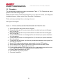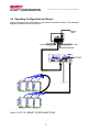
1
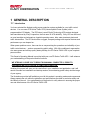
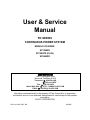
User & Service
Manual
PD SERIES
CONTINUOUS POWER SYSTEM
MODELS COVERED:
SP1250PD
SP1250PD (PLUS)
SP2000PD
CLARY CORPORATION
150 E. Huntington Drive
Monrovia, California 91016
Telephone 626-359-4486
800-44 CLARY
Fax. 626-305-0254
World Wide Web HTTP: // WWW.CLARY.COM
E-Mail SALES @ CLARY.COM
Information contained herein is the property of Clary Corporation, is proprietary,
confidential, and not to be disclosed, disseminated or used except for the purpose
provided by
CLARY CORPORATION
P/N 510-14643, REV. NR
09/2005
THE CONTINUOUS POWER COMPANY
TABLE OF CONTENTS
1
GENERAL DESCRIPTION ......................................................................................... 5
1.1
1.2
1.3
1.4
2
GENERAL CHARACTERISTICS ............................................................................. 14
2.1
2.2
3
Introduction .................................................................................................................... 27
Normal Mode ................................................................................................................. 28
Battery System Status ................................................................................................... 28
Power System Status .................................................................................................... 30
UPS System Status ....................................................................................................... 31
UPS Information............................................................................................................. 32
Event Log....................................................................................................................... 33
Options........................................................................................................................... 33
Time and Date ............................................................................................................... 36
Relays ............................................................................................................................ 37
CARE AND MAINTENANCE.................................................................................... 42
5.1
5.2
5.3
5.4
6
Installation...................................................................................................................... 20
Preparation ....................................................................................................................20
Procedure ......................................................................................................................22
Operating Configuration and Setup: .............................................................................. 23
Start-up .......................................................................................................................... 24
Optional Communication Procedure.............................................................................. 25
PROGRAMMABLE LCD DISPLAY.......................................................................... 27
4.1
4.2
4.3
4.4
4.5
4.6
4.7
4.8
4.9
4.10
5
Characteristics ............................................................................................................... 14
Specifications.................................................................................................................17
INSTALLATION AND OPERATIONS ...................................................................... 20
3.1
3.2
3.3
3.4
3.5
3.6
4
Introduction ...................................................................................................................... 5
Operating Modes ............................................................................................................. 6
Physical Description......................................................................................................... 8
Summary Of Connectors – Bypass Box ........................................................................ 12
Safety............................................................................................................................. 42
Preventive Maintenance ................................................................................................ 43
Trouble Analysis ............................................................................................................ 44
Service and Repair ........................................................................................................ 45
SCHEMATICS .......................................................................................................... 46
WARRANTY ................................................................................................................... 47
2
THE CONTINUOUS POWER COMPANY
LIST OF FIGURES
Figure 1: FRONT PANEL VIEW (N).................................................................................... 9
Figure 2: BYPASS BOX ...................................................................................................... 12
Figure 3: BYPASS BOX with GFCI Option ...................................................................... 13
Figure 3: UPS TO CABINET INTERCONNECTIONS.................................................... 23
Figure 4: SIGNAL/RS232 PIN ASSIGNMENTS.............................................................. 26
LIST OF TABLES
Table 1: FIGURE 1 DESCRIPTIONS .............................................................................. 10
Table 2: BYPASS BOX DESCRIPTIONS ........................................................................ 12
Table 3: BYPASS BOX DESCRIPTIONS ........................................................................ 13
Table 4: ELECTRICAL SPECIFICATIONS...................................................................... 17
Table 5: Physical Specifications, UPS Electronics Module ........................................... 18
Table 6: PHYSICAL SPECIFICATIONS........................................................................... 18
Table 7: ENVIRONMENTAL SPECIFICATIONS ............................................................ 18
Table 8: BATTERY SPECIFICATIONS ............................................................................ 18
Table 9: CLARY OutPostTM BATTERIES* ....................................................................... 19
Table 10: RECOMMENDED INSTALLATION EQUIPMENT ........................................ 21
Table 11: TYPICAL INSTALLATION PROCEDURE FOR TRAFFIC UPS................. 22
Table 12: LIST OF RULES ................................................................................................. 40
Table 13: ALARMS AND FAULTS .................................................................................... 41
Table 14: DEFAULT SETTINGS ....................................................................................... 41
Table 15: PREVENTIVE MAINTENANCE SCHEDULE ............................................... 44
3
THE CONTINUOUS POWER COMPANY
“IMPORTANT SAFETY INSTRUCTIONS”
“SAVE THESE INSTRUCTIONS”
This manual contains important safety instructions that should be followed during installation
and maintenance of the UPS and batteries. The instructions should be followed during installation
and maintenance of the UPS and batteries. Be aware of the following symbols and their meaning
as they appear throughout the manual:
This symbol indicates that
dangerous voltage
constituting a risk of
electrical shock is present
within the unit.
!
This symbol indicates that
there are important
operating and
maintenance instructions
in the literature
accompanying this unit.
CAUTION
RISK OF ELECTRIC
SHOCK DO NOT OPEN
!
Earth Ground Symbol:
On / Off Symbol:
Maximum Ambient Temperature 74° C.
This unit intended for installation in a controlled environment (temperature controlled, indoor area
free of conductive contaminants).
CAUTION – Do not dispose of batteries in a fire. The batteries may explode.
CAUTION - Do not open or mutilate the batteries. Released electrolyte is harmful to the skin and
eyes. It may be toxic.
CAUTION - A battery can present a risk of electrical shock and high short circuit current. The
following precautions should be observed when working on batteries.
1. Remove watches, rings, or other metal objects.
2. Use tools with insulated handles.
FCC-Rules
This equipment generates and uses radio frequency energy and if not installed and used properly in strict accordance with the
manufacturer's instructions, may cause interference to radio and television reception. All units in this manual have been tested and
found to comply with the limits for a Class A computing device in accordance with the specifications in Subpart J of Part 15 of FCC
Rules, which are designed to provide reasonable protection against such interference in a commercial installation. However, there is
no guarantee that interference will not occur in a particular installation. If this equipment does cause interference to radio and
television reception, which can be determined by turning the equipment off and on, the user is encouraged to try to correct the
interference by one or more of the following measures:
Reorient the receiving antenna.
Relocate the UPS with respect to the receiver.
Move the UPS away from the receiver.
Plug the UPS into a different outlet so that the UPS and receiver are on different branch circuits.
If necessary, the user should consult the dealer or an experienced radio/television technician for additional suggestions. The user may
find the following booklet prepared by the Federal Communications Commission helpful:
"How To Identify and Resolve Radio-TV Interference Problems"
This booklet is available from the U.S. Government Printing Office, Washington, DC 20402, Stock No. 004000003454.
4
THE CONTINUOUS POWER COMPANY
1 GENERAL DESCRIPTION
1.1 Introduction
You have selected the highest quality power protection system available for your traffic control
devices. You now own a PD Series Traffic UPS (Uninterruptible Power System) with a
programmable LCD display. The PD Series is an all Digital Technology UPS product designed
and manufactured by Clary Corporation, the first name in UPS reliability. Clary UPS can be found
on naval warships and submarines, hospital operating rooms, labs, water treatment plants and
traffic intersections. The PD Series offers a rugged, compact package with superior features and
performance you can depend on.
When power problems occur, there can be no compromising the operations and reliability of your
traffic control devices - - and no compromising public safety. With fully conditioned, regenerative,
sine wave power and military-quality battery backup, the PD Series Traffic UPS is your complete
power solution.
This Owner’s Operating Manual is provided with your new PD Series Traffic UPS. It will enhance
your understanding of the product and its functions.
WE STRONGLY URGE YOU TO READ THIS MANUAL COMPLETELY, PRIOR TO
BEGINNING INSTALLATION OR ATTEMPTING OPERATION.
Studying this manual will save you time and effort in your installation and application, and it will
assure a trouble free installation and startup session, thus enhancing public safety and the image
of your agency.
The illustrations provided will familiarize you with this product’s operating modes and components.
Always operate the unit within the guidelines and specifications provided to maximize safety and
the lifetime of the unit. Your understanding of the product is a key element in assuring the proper
use and effectiveness of the PD Series Traffic UPS.
5
THE CONTINUOUS POWER COMPANY
1.2
Operating Modes
Clary’s PD Series Uninterruptible Power Systems (UPS) are designed for powering low power
(i.e., LED & NEON) traffic & pedestrian indications, plus critical traffic control devices (i.e.,
controllers, modems, CMU’s, etc.). The power system consists of three elements, which work
together to provide critical loads with continuous, conditioned, regulated, sinusoidal waveform
power that is free from disturbances such as spikes, surges, brownouts or blackouts. These
elements are the:
1. UPS Module – (UPS)
2. Bypass Box
3. Battery Module
Backup power is achieved with a set of rechargeable, SVRLA (sealed valve-regulated lead-acid),
maintenance-free, AGM (absorbed glass mat), batteries. The complete UPS system is controlled
by an onboard digital microprocessor at all times.
There are two basic modes of operation:
•
•
Offline (Standby Operating Mode)
Online (Continuous Operating Mode)
In both modes, the UPS continuously generates 120V AC power. The selected mode determines
when and how the UPS generated power is applied to the loads in the traffic cabinet.
Standby Operating Mode (OFFLINE):
During Standby operation, utility (AC) power enters the Bypass Box then into the UPS (if Bypass
Box is switched to UPS) and passes through a normally closed relay, then directly out to the
cabinet power bus, PDA, etc. This utility power is used to power the intersection until a power
disturbance occurs at which time, the relay is switched, routing the UPS generated AC power to
the cabinet power bus. Typically, the UPS will then be drawing its power from the battery pack.
This operation continues until good utility power is restored, after which, the relays switch back to
route the utility power to the loads.
With Standby operation, 0.5 seconds (user programmable from 30ms to 2.5sec) after an outage is
detected, standby power is connected to the system and if desired, the Flash Command is
initiated, forcing the cabinet into Flash Mode operation. Depending on the size of the battery
system being used and the loading on the power system, backup power can continue for several
hours. NOTE: If the flash mode operation is not desired, make sure intersection load is not over
875 watts.
6
THE CONTINUOUS POWER COMPANY
When utility power returns, (or upon application of generator power) the PD Series UPS waits 30
seconds to be sure that the utility power has stabilized. After this built-in safety delay utility power
is restored to the cabinet. The battery charger then recharges the batteries in typically 10 to 20
times (depending on the load) the duration of the outage or battery discharge time (whichever is
shorter).
The UPS can be set to force a break in power of 2.5 seconds after utility power returns. This is
optional (not the default) and is used in intersections when a hard-restart needs to be applied to
various devices when returning from flash.
With Standby operation, the ONLY required change to cabinet wiring occurs by the introduction of
the Bypass Box. Removal and Replacement (R&R) of the UPS module is quick and easy even
with traffic control devices (TCD’s) connected to the UPS. If no TCD’s are plugged into the UPS
module (i.e. being used for LED flash backup only), R&R of the UPS module (for upgrades or in
the rare event of UPS failure) can be done without powering down the cabinet or otherwise
affecting cabinet operation in any way.
Continuous Operating Mode (ONLINE):
Continuous operation is used for low power applications such as full LED intersections, power to
the intersection is continuously conditioned and backed up by the UPS. Within the limitation of
the battery capacity, virtually all brownout and power outages are eliminated.
SP1250PD (PLUS) OPTIONAL
The PLUS has an extended load option that will allow 1400watts peak load for ten seconds. This
option allows for support of intersections that have not yet replaced the yellow incandescent traffic
lamps.
Additional Notes on Operating Modes:
•
The PD Series Traffic UPS is designed for compatibility with, and complete transparency
to, all traffic signal cabinet functions including police panel operation.
RELAY CONTACTS:
The UPS includes six (6) or eight (8) sets of normally-open (NO) and normally-closed (NC) relay
style contacts. The contacts are intended to connect to the Flash controllers or other devices in
the traffic cabinet. The contacts are actuated at various times as a means of signaling these
devices of important aspects of current operation. These relays can be programmed from the
Front Panel LCD Display. You can set any of the relays to a certain condition listed in Table 11.
See section 4.10 for programming instructions.
7
THE CONTINUOUS POWER COMPANY
1.3 Physical Description
This section will point out and illustrate the various indicators, functions and controls of the PD
Series UPS. The important attributes of the PD Series unit are numbered to assist you in locating
them on your machine and also to fully explain its function and how it relates to system operation.
Numbers on the drawing will correspond to the operating component’s name at the bottom with a
brief identification. In the next section, a complete explanation of all numbered items will be
enhanced to ensure you have a full understanding of the operation of this system.
Visual indicators used on the front panel are long lasting, very efficient, light emitting diodes
(LED). When operating the push-button switches, always hold the switch in for at least two
seconds to insure function confirmation. This feature has been implemented into the system
design to avoid inadvertent operation of any of the user-available functions.
Figure 1 is the front view of the model SP1250PD-N.
8
THE CONTINUOUS POWER COMPANY
Table 1 describes items 1 – 22.
11
8
10
9
5
4
3
15
7
6
17
19
18
N
N
N N
N N
N N
N N
N N
N N
N N
C
C
C
C
C
C
C
C
C
O
C O
C O
C O
C O
C O
C O
C O
AC INPUT BREAKER
15A/250VAC
OUTPUT
AC
IN/OUT
DC INPUT BREAKER
BATT TEST
POINTS
DC IN
+
_
GND
OUTPUT
1
21
20
2
14
Figure 1: FRONT PANEL VIEW
9
12
16
13
22
THE CONTINUOUS POWER COMPANY
Table 1: FIGURE 1 DESCRIPTIONS
PANEL VIEW DESCRIPTIONS
1
SYSTEM POWER SWITCH
12
DC INPUT – Protection circuit breaker
for battery
2
INPUT AC LINE BREAKER
13
DC IN – Input receptacle for all DC power
(to Batteries)
3
LCD DISPLAY
14
AC IN / OUT – Input terminal block for all
AC power to Bypass Box
4
SELECT/MENU MODE
15
RELAYS – NO/NC Contacts for Flash
5
ENTER/SHOW TIME
16
BATTERY TEST POINTS
6
UP ARROW +
17
AUX. TEMP. SENSOR – Input for
Optional Aux. Temp. Sensor
7
DOWN ARROW -
18
RS232 – Computer communications
signals
8
COLD START – DC start switch
19
SIGNAL – Open-collector signal
contacts
9
COLD START INDICATOR
20
CIRCUIT BREAKER – Protection for
output receptacles
10
ALARM SILENT/TEST – Dual
function switch
21
OUTPUT RECEPTACLES – Continuous
power receptacles
11
ALARM SILENT/TEST
ACKNOWLEDGE INDICATOR
22
GND - GROUND POINT
10
THE CONTINUOUS POWER COMPANY
SUMMARY OF INDICATORS AND CONTROLS
SYSTEM POWER SWITCH - The main control switch that engages utility power to the entire unit.
By activating this switch it initializes normal operation.
DC INPUT - A two pole, 20A (25A for SP1250PD (PLUS) & SP2000PD) circuit breaker used to
connect the battery to the internal UPS electronics. It also protects against over-current situations
in the battery circuit.
INPUT AC LINE BREAKER - The input line protection device to limit excessive current draw to
the system on over-loads. Rated 15A/250V (20A for SP1250PD (Plus) & SP2000PD).
COLD START - A momentary push-button switch to activate the system in the event no utility
power is available. The system will be allowed to start up by using power from the battery.
Depress this switch, the indicator above it will light, and hold it in until the audible alarm beeps
once. The system will maintain a load for a period of time depending upon the condition of the
battery. DC INPUT breaker must be ON.
ALARM - This is a fault indicator that will light in the event that the inverter generator is nonoperable. This could be due to an over-temperature situation or an inverter malfunction.
!
NOTE - Cold Start and Alarm Silent switches must be held in for at least two
seconds to engage their function. This is to prevent any inadvertent switch
operation.
RS232 - A DB-9 subminiature, female connector that outputs true RS232 communications
signals.
UPS OUTPUT - A NEMA type duplex, 5-15R output connector that provides continuous power.
This receptacle is connected to the bypass line when the inverter is not running.
UPS OUTPUT CIRCUIT BREAKER - A 15A protective circuit breaker. Protects the UPS
OUTPUT 5-15R connector noted above.
SIGNAL - A DB-9 subminiature, female connector that outputs the open-collector signal contacts
that generate a low state during utility interrupt, low battery and inverter off conditions.
AC INPUT - A six-position plug in connector provided for AC power to and from the UPS to the
Bypass Box.
DC INPUT - A two-position connector provided for battery power to the UPS.
RELAYS – Six or Eight sets of normally open (NO) and normally closed (NC) contacts. These
contacts are programmable thru the LCD display. See section 4.10 for instructions.
LCD DISPLAY & PUSH BUTTONS – An LCD Display showing UPS system data, status and
settings. See section 4.
11
THE CONTINUOUS POWER COMPANY
1.4 Summary Of Connectors – Bypass Box
Figure 2: BYPASS BOX
9
1
2
4
3
1 – To Utility - H
2 – To Utility - N
3 – To UPS IN - H
4 – To UPS IN - N
5 – To UPS OUT - H
5
6
7
8
6 – To UPS OUT - N
7 – To CABINET - H
8 – To UPS OUT - N
9 - Generator Input (Optional)
Table 2: BYPASS BOX DESCRIPTIONS
12
THE CONTINUOUS POWER COMPANY
Figure 3: BYPASS BOX with GFCI Option
11
10
1
2
1 – To Utility - H
2 – To Utility - N
3 – To UPS IN - H
4 – To UPS IN - N
5 – To UPS OUT - H
6 – To UPS OUT - N
3
4
5
6
7
8
7 – To CABINET - H
8 – To UPS OUT - N
9 - Generator Input (Optional)
10 - GFCI Outlet (Optional)
11 - Circuit Breaker for GFCI
Table 3: BYPASS BOX DESCRIPTIONS
13
9
THE CONTINUOUS POWER COMPANY
2 GENERAL CHARACTERISTICS
2.1 Characteristics
Overview
The Clary PD Series Traffic UPS is a turnkey, true on-line, power conditioner and battery backup
or uninterruptible power system (UPS) designed for the extreme environments found in traffic
cabinets (-40 to + 74 deg C).
The Clary PD Series, with its standard 41Ahr battery pack, is capable of operating, a full LED
intersection for over 2 hours at 700W (watts) output. A typical intersection consuming 450W can
be powered for approximately 4 hours. In Red-Flash operation, which consume only about 300W,
over 6 hours of backup is possible. These times assume fully charged batteries at the ambient
temperature of 25C.
Operation
The Traffic UPS is capable of producing – simultaneously -- full regenerated and regulated, true
sine wave power, with standby and continuous AC outputs. The Bypass Box is the link between
the utility power, the UPS power, and the loads.
When utility power is adequate, the UPS routes that power to the loads. Upon loss of utility power
the Traffic UPS routes UPS generated power to the loads. In the event of UPS failure and/or
battery depletion, the UPS will ensure that it will drop out and return to utility power when
available. The traffic control system will then default to normal operational mode.
The Bypass Box enables removal and replacement of the Traffic UPS without shutting down the
traffic control system (i.e. “hot swap” capability).
For 170 type cabinets, upon loss of power the Traffic UPS can actuate the existing Flash Transfer
Relays (FTRs), Mercury Contactor (MC) or Railroad Preemption to allow the traffic control system
to put the cabinet into Flash Mode operation.
Existing Flasher Modules and Flash Transfer Relays are utilized. The Traffic UPS does not
duplicate or take over flash operation or flash transfer relay functions.
The Traffic UPS is capable of providing continuous, fully regenerated, conditioned, regulated,
sinusoidal (AC) power to selected devices such as signal controllers, counters, modems,
communications hubs, NTCIP adapters, video equipment, etc.
To facilitate emergency crews and police activities, the Traffic UPS is compatible with police panel
functions (i.e. “Signals OFF” switch must kill power to the field wiring even when on UPS/Battery
power).
14
THE CONTINUOUS POWER COMPANY
Utility Voltage Windows and Battery Operation
The UPS operates from utility if the utility voltage is between 85 and 135 VAC. When the utility
falls below 85 VAC or climbs above 135 VAC the UPS operates from the batteries. In the
Standby modes of operation, the UPS relay is activated when the utility is below 100 +/- 2 VAC or
above 130 +/-2 VAC.
There is a programmable noise rejection window, which specifies how the UPS system treats
small time-duration power glitches. Power disturbances must last at least 40ms to trigger change
in operation. Small disturbances on this order occur frequently due to many different conditions.
These disturbances, however, are not detrimental to traffic controllers. To minimize nuisance
switching this noise rejection window is implemented.
After operating in Standby mode, the UPS monitors the utility voltage. When this voltage is
restored to adequate conditions for 30 seconds, the UPS returns utility power to the cabinet.
Description
The Traffic UPS consists of three major components, the UPS Power Module, the Bypass Box,
and the Battery System.
The UPS Power Module consists of the following:
•
True on line, double conversion, pure sine wave, high frequency inverter utilizing IGBT
technology.
•
Programmable LCD Display.
•
Two separate DB9F connectors for remote signal alarms and true RS232 monitoring and
remote communications.
•
Auxiliary Temp Sensor
•
Multi-stage, temperature compensated battery charger.
The Bypass Box. A three-pole, double-throw switch that switches both hot and neutral lines to
the UPS or cabinet.
The Battery Module. The battery is comprised of one or more strings of 6 individual 12V batteries
connected in series for a total string voltage of 72V DC nominal. The SP2000PD consists of 8
individual 12V batteries connected in series for a total string voltage of 76V DC nominal.
The batteries are extreme temperature, deep cycle, AGM/VRLA (Absorbed Glass Mat/ Valve
Regulated Lead Acid) batteries that have been field proven and tested by the U.S. military. The
OutPostTM batteries supplied by Clary Corporation are certified to operate at extreme
temperatures from –40°C to +74°C.
15
THE CONTINUOUS POWER COMPANY
The batteries are provided with appropriate interconnect wiring harness. Optional battery
mounting trays and brackets are available.
The interconnect cable connects to the base module via a quick-release circular connector.
The UPS module includes a charger that replenishes the Battery Pack whenever possible and
required. This charger operates with a maximum charging current of 0.6A. An optional “Fast
Charger” module can be installed into the UPS module to increase the charging current to over
3.5A.
Mounting/ Configuration
NEMA Style: mounting method is shelf-mount or wall-mount.170 Style: Mounting method is 19”
rack-mount. Shelf angles or rails, typically supplied by others, are available as optional
accessories.
Battery construction includes heavy-duty, inter-cell connections for low-impedance between cells,
and heavy-duty plates to withstand shock and vibration.
16
THE CONTINUOUS POWER COMPANY
2.2 Specifications
The various specifications of the UPS system are provided in the following tables.
Table 4: ELECTRICAL SPECIFICATIONS
Electrical Specifications
Input Specification
Nominal Input Voltage
120 VAC, Single Phase
Input Voltage Range
85 VAC to 135 VAC
Input Frequency
45 to 65 Hz (+/- 5%)
Input Configuration
3 Wire (Hot, Neutral & Ground)
Input Current (Max. draw)
8.8 amps, Power-Factor Corrected
Input Protection
Input breaker 15 amps (20 amps PD1250 (PLUS) &
SP2000)
Output Specification
Nominal Output Voltage
120 VAC, Single Phase
Power Rating
1.25 KVA (1250VA/875W), 2KVA (2000VA/1400W)
Output Voltage Regulation
+/- 2% for 100% step load change and from
High battery to Low battery condition
Output Frequency
50 or 60 Hz (+/- .5%) unit not in sync.
Output Configuration
3 Wire (Hot, Neutral & Ground)
Output Wave Form
True Sine wave
Overload capability
110% for 10 minutes 200% for 50 milliseconds
2k PLUS 160% for 10 seconds
Fault clearing
Current limit and automatic shutdown
Short circuit protection
Current limit and automatic shutdown
Efficiency
90% at full load (on utility)
Load Power Factor
.7 lagging through unity to .7 leading
17
THE CONTINUOUS POWER COMPANY
Table 5: Physical Specifications, UPS Electronics Module
Physical Specifications, UPS Electronics Module
Dimensions:
Width = 19”, Depth = 10”, Height = 6”
Weight:
UPS: 20 lbs., Shipping weight: 25 lbs.
Table 6: PHYSICAL SPECIFICATIONS
Physical Specifications, Bypass Box
Dimensions:
Width = 7”, Depth =2.5”, Height =4.5”
Weight:
BYPASS BOX: 5 lbs., Shipping weight: 5 lbs.
Table 7: ENVIRONMENTAL SPECIFICATIONS
Environmental Specifications
Temperature:
- 40°C to +74°C.
Table 8: BATTERY SPECIFICATIONS
Battery Specifications
Temperature:
– 40°C to +74°C.
Ampere-Hour ratings:
see Table 9
Hydrogen gas emissions: meets Mil-Spec #MIL-B-8565J
18
THE CONTINUOUS POWER COMPANY
Table 9: CLARY OutPostTM BATTERIES*
Estimated Runtime
(Per set @ 77°F / 25°C)
(New Batteries, fully
charged)
Clary
Volts/
Part. No.*
A-hrs.
OP72C
(Set of
Six
Batteries)
12
VDC/
300
Watts
6.5
500
700
875
Watts Watts Watts
4.0
2.5
1.8
Hrs.** Hrs.** Hrs.** Hrs.**
Unit
Weight
Overall Dimensions
Per Battery Inches (cm.)
Lbs.
Length
Width
Height
(Kg.)
L
W
H
29
7.68
5.15
7.9
(13.2)
(19.6)
(13.1)
(20.1)
41 AH
*OP72X battery sets include six (6) batteries per set. Wired in series, each set provides 72 VDC.
** Actual times may vary, runtimes are dependent on many factors.
Lower/Higher AH capacity batteries, allowing less or more runtime, are available on special order.
Contact factory for more information.
Communications, Controls & Diagnostics
Alarm Function Monitoring: The traffic UPS comes standard with a DB-9F connector with open
collectors (40 V @ 20 mA) indicating On-Battery, Low-Battery, Timeout on-battery and Alarm.
A separate RS232 Interface is provided via a DB-9F connector allowing full, interactive, remote
computer monitoring and control of the UPS functions via standard UPS protocols.
Optional TCPIP/Ethernet available, contact factory for more information.
Front Panel controls: Power ON, Cold (DC) Start, Alarm Silence, Battery Test, Bypass Circuit
Breaker, and DC/Battery Circuit Breaker.
Options
Battery Tray to hold three (3) OP72C batteries is 19” wide for use in 170 type cabinets and
mounts on standard RETMA rails.
Swing-out Battery Box, mounts on right rail inside back door of 170 type cabinets. Box is designed
to hold tree (3) OP72C batteries
Fast Battery Module, optional module provides extra charging current to the batteries when
required, reducing charging time.
19
THE CONTINUOUS POWER COMPANY
3 INSTALLATION AND OPERATIONS
3.1 Installation
The UPS system is typically rack or shelf mounted in standard traffic cabinets. When determining
how to position the UPS system inside your cabinet, the following requirements MUST be met.
•
The installation site MUST maintain an ambient air temperature of less than 165oF (74oC).
•
The air inlets, vents and fan MUST NOT be obstructed or blocked in any way. There MUST
BE clearance around each air-inlet and vent.
•
The air should remain free from excessive dust and chemical fumes.
•
Total power requirements to be drawn from the UPS must not exceed the rated power of the
UPS.
Please note these items when designing the UPS system’s mounting hardware:
•
3.2
The front panel is designed to fit in a standard 19" rack. This panel fills a 6-inch slot.
Preparation
Installation of the PD Series Traffic UPS must be preceded by careful preparation. The following
steps are typical:
• Ensure that the Installation Requirements will be met. (See previous section).
• Read this manual thoroughly.
• Assemble wiring diagrams.
20
THE CONTINUOUS POWER COMPANY
•
•
•
•
•
Unpack and ensure that all UPS System components are on-hand and operative:
o UPS System Module
o (Bypass Box)
o Battery Module (6 batteries w/cabling)
Collect appropriate mounting hardware for the particular installation.
o For 170/332 cabinets only, one or two battery trays (per shipping documents,
depends on version purchased)
Assemble your tools and inventory your equipment. Table 10 is a checklist of items
that have proved useful during previous installations.
Contact the responsible agencies to schedule a brief power down (10 to 15 minutes) at
the intersection(s) affected.
Allot 2 hours of time for the installation.
Table 10: RECOMMENDED INSTALLATION EQUIPMENT
Armored sheathing (cable protector)
Connectors (butt type and
insulated)
Cordless drill w/ bits and a spare
Crimpers (for insulated and nonbattery pack
insulated connectors)
Dikes
DVM w/ probes
Electrical Tape
Flat Head screwdriver
Hardware in spill-proof carrying case
Hold-downs (adhesive back)
Nut Driver Set
#2 Phillips head screwdriver
Phillips head drill bit
Propane torch (miniature) or
cigarette lighter
Shrink tubing
Socket Set
Socket Wrench
Current clamp meter
Wire cutters
Wire strippers
21
THE CONTINUOUS POWER COMPANY
3.3 Procedure
The recommended installation procedure is presented in Table 11 . The Table refers to, which
presents a schematic wiring diagram.
Read through the entire procedure before beginning. If any steps are unclear, do not begin the
installation process – please contact Clary Corporation for assistance.
Finish each step completely before continuing to the next.
See Figure 4 for diagram.
Table 11: TYPICAL INSTALLATION PROCEDURE FOR TRAFFIC UPS
1. Mount Bypass Box and position switch to Bypass.
2. Disconnect utility input H from input terminal block in cabinet and connect to Bypass
Box (To Utility H).
3. Disconnect utility input N from input terminal block in cabinet and connect to Bypass
Box (To Utility N).
4. Connect AWG #10 black wire from Bypass Box (To Cabinet H) to input terminal block
(H) in the cabinet.
5. Connect AWG #10 white wire from Bypass Box (To Cabinet N) to input terminal block
(N) in the cabinet.
6. Connect the AWG #10 green wire from the provided cable assembly to the ground bus
terminal in the cabinet.
7. Mount UPS in cabinet and make sure system switch is in the “OFF” position.
8. Mount Batteries and connect all interconnect connectors from the battery cable.
9. Connect Cable from the Bypass Box to the UPS.
10. Connect battery cable to UPS. Make sure the six or eight batteries are wired in series
(+ to -) with 72VDC or 96VDC full potential across complete string.
11. Connect Flash connections to the UPS.
12. Test installation for proper operation.
13. Document installation.
22
THE CONTINUOUS POWER COMPANY
3.4 Operating Configuration and Setup:
Figure 3 shows how the UPS System is connected to the traffic cabinet. This schematic
diagram illustrates the interconnections.
N
N N
N N
N N
N N
N N
N N
N
N N
C
C
C
C
C
C
C
C
O
C O
C O
C O
C O
C O
C O
C
C O
OUTPUT
AC INPUT BREAKER
15A/250VAC
AC
IN/OUT
DC INPUT BREAKER
BATT TEST
POINTS
DC IN
+
_
OUTPUT
Figure 4: UPS TO CABINET INTERCONNECTIONS
23
GND
THE CONTINUOUS POWER COMPANY
3.5 Start-up
Once the system has been properly installed, it is ready to operate. The following procedures will
explain how to start-up the system while wired into rated electrical power and also how to start-up with
no AC power available.
Normal Operation on AC Start-Up:
• Verify that the unit is wired into properly rated electrical power through the Bypass Box.
• The AC IN and DC IN cables must be fully connected to the unit. Position the DC breaker to the ON
position.
• Position the System Power Switch to the ON position.
After switching ON, the UPS performs a self-test and the display will show:
CLARY CORPORATION
mm/dd/yy
hh:mm:ss
After completion of the self-test, the display will show the default screen (values are examples).
LOAD 50% BATT 100%
AC LINE OK, INV ON
• Battery Operation after AC Start-Up:
When Utility power is lost, the Alarm LED will blink and the display will show: (values are examples)
LOAD 50% BATT 90%
AC LINE BAD, INV ON
In stand-by mode, inverter power will be supplied to the cabinet in two timing steps to control the traffic
equipment wired to the PD system, now powering the cabinet in flash mode. In continuous mode, the
cabinet operation will continue without interruption.
If the unit is allowed to operate until batteries are exhausted, it will time out and shut off completely. If
power were to return, the unit will automatically restart and return to the condition it was in at the
moment it went into Battery Mode.
Once power is returned, if in standby mode, inverter power to the traffic equipment will be
discontinued through the UPS in a sequenced timing operation. The UPS will keep the the intersection
in flash for 30 seconds to ensure Utility power is stable. In continuous mode, the cabinet operation
will continue to operate without interruption.
DC Start Operation (Cold Start)
If no utility power is available at the time backup power is required, the unit may be started to
accomplish abbreviated tasks. The limitations of the battery prevent extended operations at full load.
• Position the DC Input Breaker to the ON position.
• Position the System Power Switch to the ON position.
• Push and hold in the COLD START switch until the audible alarm beeps.
24
THE CONTINUOUS POWER COMPANY
The unit will start up similarly to normal AC start-up except the Alarm LED will continue to blink. It will
now operate as described above in battery operation.
3.6 Optional Communication Procedure
The UPS system includes additional interfaces for communications to host computers or other similar
devices. Their use is optional, but allows for remote monitoring and control of the power system.
Effective utilization of these capabilities will enhance the reliability of the traffic power system.
There are two DB-9, subminiature, female connectors. These are provided for communications links to
a computer or sophisticated monitoring device. These two connectors are labeled and used as:
o
SIGNAL provides open collector type contact closures that signal AC Input Fail/Timer, Low
Battery and UPS ON conditions.
o
RS232 is a true communications signal port. This port connects to standard PC-type serial
ports.
See Figure 4 for Pin assignments.
25
THE CONTINUOUS POWER COMPANY
SIGNAL PORT
2- AC INPUT FAIL/FLASH TIMER
3- UPS ON
RS232 PORT
1- LOW BATTERY
2- TX
4568-
34568-
COMMON SIGNAL RETURN
LOW BATTERY
+9VDC
+9VDC
SIGNAL: DB-9
CONNECTOR
RX
RS232 SHUTDOWN
GROUND
+9V
AC FAIL
RS232: DB-9
CONNECTOR
Figure 5: SIGNAL/RS232 PIN ASSIGNMENTS
26
THE CONTINUOUS POWER COMPANY
4 PROGRAMMABLE LCD DISPLAY
4.1 Introduction
The LCD display on the UPS front panel is used to show various operational parameters of the UPS (in
real time) as well as other important system information. It is also used to program options and set
points for many UPS functions.
The LCD display operates in two main modes:
1. Normal Mode - The default mode of operation for displaying real time UPS parameters. When
left unattended, the display will always revert back to normal mode.
2. Menu Mode - Used for accessing additional system information and for programming any
modifiable UPS parameters. Menu mode is accessed by pressing and holding the Select/Menu
Mode button for approximately two seconds.
The Programmable LCD Display is operated by the 4 push button switches. Once in Menu mode, the
following eight main menus can be selected:
1. Battery system status
2. Power system
3. UPS system
4. UPS info
5. Event log
6. Options
7. Time/Date
8. Relays
From the normal mode’s main screen, depress and hold the SELECT/MENU MODE button until Menu
mode is entered (The screen will change to the Battery System status screen). Press the
SELECT/MENU MODE button to go to the menu you want then press ENTER. You will now be in one
of the seven menus.
27
THE CONTINUOUS POWER COMPANY
4.2 Normal Mode
The Normal mode’s main screen shows the Load and Battery percentage, AC input status and Inverter
status. The Normal mode display will look something like the following.
LOAD 50% BATT 90%
AC LINE BAD, INV ON
To see the time and date, press the ENTER/SHOW TIME button.
LOAD 50% BATT 90%
mm/dd/yy
hh:mm:ss
4.3 Battery System Status
STATUS: BATTERY Syst
Once at this screen, press the ENTER/SHOW TIME button. Then press the SELECT/MENU MODE
button to go through the Battery System Status menu.
St20: Battery Status
78V => BAT is OK
Shows Battery status and Voltage
St21: Power Events
001 Event(s)
Shows number of times UPS went to Battery Power.
To clear events, press and hold both the UP and Down Arrow buttons simultaneously until the event
count clears.
St22: Battery Usage
10.5 hrs
Shows total time in hrs that UPS was running off of Battery Power.
To Clear usage, press and hold both the UP and Down Arrow buttons simultaneously until the time
clears.
28
THE CONTINUOUS POWER COMPANY
St23: Estim Bat Time
10 minutes
Shows estimated time remaining when UPS is running on Battery Power.
St24: Bat Condition
Battery is GOOD!
Shows condition of the Batteries.
St25: Bat Install
mm/dd/yyyy
Shows Battery installation date. Can only be set to the current date. To reset, press and hold both the
UP and Down Arrow buttons simultaneously until it resets to the current date.
St26: Battery Type
72 Volts ??Ahr
Shows the nominal battery voltage and the battery Amp hours.
29
THE CONTINUOUS POWER COMPANY
4.4 Power System Status
STATUS: POWER System
Once at this screen, press the ENTER/SHOW TIME button. Then press the SELECT/MENU MODE
button to go through the Battery System Status menu.
St30: Input Line Pwr
115Vrms 60Hz 1.5A
Shows the Input line power Voltage, Frequency and Current going into the UPS.
St31: Output Pwr Src
UTILITY
Shows the power source which the UPS is currently running off of (UTILITY or BATTERY).
St32: Output Pwr/Ld
120Vrms 60Hz
50%
Shows the Output Voltage, Frequency and Load percentage.
30
THE CONTINUOUS POWER COMPANY
4.5 UPS System Status
STATUS: UPS SYSTEM
Once at this screen, press the ENTER/SHOW TIME button. Then press the SELECT/MENU MODE
button to go through the Battery System Status menu.
St40: Operating Mode
NORMAL
Shows the operating status of the UPS (NORMAL, BACKUP,……..etc).
St41: Alarm Status
1 ALARM
Shows the Alarm status and number of alarms which are currently active (OVERTEMP, OVERLOAD,
OUTPUT BAD, GENFAIL, INPUT IS BAD,………...etc).
St42: Temperature
Loc 25C Rem 25C
Shows the local and remote temperature in degrees Celsius. Remote temperature readings are available
only when an auxiliary temperature sensor is installed.
St43: Shutdown Stat
NO SHUTDOWN PENDING
Shows shutdown status of UPS.
St44: POWERDOWN Stat
f_code: 00 BATDEAD
Shows the reason the UPS shutdown previously with an associated error code.
31
THE CONTINUOUS POWER COMPANY
4.6 UPS Information
Status:
UPS Info
Once at this screen, press the ENTER/SHOW TIME button. Then press the SELECT/MENU MODE
button to go through the UPS Information menu.
St50: UPS Model #
SP1250I
Shows UPS Model#
St51: UPS Pwr Rating
1250VA
Shows UPS power rating in VA.
St52: UPS Firmware
86501-35.301
Shows the type and revision of the UPS firmware(EPROM) installed in the unit.
St53: LCD Firmware
DEV 04-15-2005
04-08-2004 REV-A
REV-B
Shows the type and revision of the firmware installed in the LCD Display. Screen shown is just an
example.
32
THE CONTINUOUS POWER COMPANY
4.7 Event Log
Status: EVENT LOG’s
Displays a history of the most recent 100 logged events. Once at this screen, press the ENTER/SHOW
TIME button. Then press the SELECT/MENU MODE button to go to the logs.
LOG# 100 AC FAIL
mm/dd/yy
hh/mm/ss
Use the Arrow Keys to scroll through the logs. Press and hold both the up and down arrow keys
simultaneously to clear all the event logs.
4.8 Options
Status: OPTION’s
Displays the current system option values and allows selected options to be modified.
Once at this screen, press the ENTER/SHOW TIME button. Then press the SELECT/MENU MODE
button to go through the options menu.
INTERFACE DELAY
current value = 2
Not used. For future use.
FLASH TRIGGER (MINS)
current value = 120
This is the time in minutes that specifies the trip point that activates the Timed NO/NC contacts on the
UPS. Used for delayed flash. Make sure you have change the Flash Status Pin to “ON” to activate this
feature. To Change the value, press the arrow buttons. Once at the desired value, press the
Enter/Show Time button to save. The screen will now show the new value. Default is 120.
33
THE CONTINUOUS POWER COMPANY
FLASH TRIGGER (VOLT)
current value = 69
This is the battery voltage that specifies the trip point that activates the Low Battery NO/NC contacts on
the UPS. Used for delayed flash. To Change the value, press the arrow buttons. Once at the desired
value, press the Enter/Show Time button to save. The screen will now show the new value. Default is
69.
BATTERY TEST (HOURS)
current value = 160
This will set the Battery Test Interval. The unit will perform a battery self test to determine the condition
of the battery. To Change the value, press the arrow buttons. Once at the desired value, press the
Enter/Show Time button to save. The screen will now show the new value. Default is 160.
CALIB PARAMETER #9
current value =
0
This calibration parameter sets the low point at which the UPS switches over to UPS Power. Used
when unit is set in the standby mode. Flash contacts will activate. It is Not recommended to change
this parameter unless instructed to do so by the factory.
CALIB PARAMETER #10
current value =
0
This calibration parameter sets the high point at which the UPS switches over to UPS Power. Used
when unit is set in the standby mode. Flash contacts will activate. It is Not recommended to change
this parameter unless instructed to do so by the factory.
TRAFFIC ONLINE OPER
current value =
ON
This screen will allow you to operate the unit “ONLINE” (Continuous Operating Mode) or “OFFLINE”
(Standby Mode). To Change the value, press the arrow buttons. Once at the desired value, press the
Enter/Show Time button to save. Be sure your load is not over the max rating of the unit before
turning the UPS ONLINE.
34
THE CONTINUOUS POWER COMPANY
LONG RETURN ALWAYS
current value =
OFF
This option is used in the “Standby Mode”. When “ON”, the UPS will force a break in power to the
cabinet for 2.5 seconds after utility power has returned. This is used when you need a hard restart to
the controller when coming out of flash. To Change the value, press the arrow buttons. Once at the
desired value, press the Enter/Show Time button to save.
LONG RETURN FLASH
current value =
OFF
This option is used in the “Continuous Operating Mode” when delayed flash is used. When “ON”, the
UPS will force a break in power to the cabinet for 2.5 seconds after utility power has returned if flash
trigger in minutes or volts occurs. This is used when you need a hard restart to the controller when
coming out of flash. To Change the value, press the arrow buttons. Once at the desired value, press
the Enter/Show Time button to save.
FLASH STATUS PIN
current value =
OFF
This enables the flash trigger in minutes option. The Timer NO/NC contacts on the UPS will activate off
the Timer. To Change the value, press the arrow buttons. Once at the desired value, press the
Enter/Show Time button to save.
UTILITY STATUS PIN
current value =
ON
This enables the Timer NO/NC contacts on the UPS to activate whenever utility power is lost.
By changing the Flash Status Pin value, the Utility Status Pin value will change to the opposite value.
To Change the value, press the arrow button. Once at the desired value, press the Enter/Show Time
button to save.
35
THE CONTINUOUS POWER COMPANY
BROWNOUT PROTECTION
current value =
ON
This feature is used only in the standby mode. The brownout protection feature allows the UPS to
switch to inverter power from utility power to the cabinet without running off of batteries when utility
power is experiencing certain brownout conditions. When the input voltage falls below 100VAC ±2V or
rises above 130VAC ±2V, the UPS switches over to inverter power but is still running off of the utility
power. As soon as the utility voltage falls below 88VAC ±2V or rises above 135VAC ±2V, the UPS then
begins to run off of battery power. This ensures that the cabinet will see no less than 100VAC or more
than 130VAC and the UPS will not use battery power if the utility voltage drops in this window.
FAILURE STATUS DELAY
current value =
OFF
Sets a 10 second delay in the utility fail signal.
AUDIBLE ALARMS <<*>>
current value =
OFF
This screen allows you to enable and disable the audible alarm. To Change the value, press the arrow
buttons. Once at the desired value, press the Enter/Show Time button to save. Default is OFF.
4.9 Time and Date
Status:
TIME/DATE
This screen allows you to set the time and date. Once at this screen, press the ENTER/SHOW TIME
button.
display TIME & DATE
Press the Select/Menu Mode button to go to the time or date that you want to change. You can set
hours, minutes, seconds, day of week, month, year and day of month.
Once you are at the screen that you want, press the Enter/Show Time button. Use the Arrow buttons to
select the value that you want. Press the Enter/Show Time button to save.
36
THE CONTINUOUS POWER COMPANY
4.10 Relays
Status:
RELAY’s
Once at this screen, press the ENTER/SHOW TIME button. Then press the SELECT/MENU MODE
button to go through the three main Relay menus.
4.10.1 ASSIGN RULE TO RELAY
SEE TABLES 12 & 13 FOR DETAILED RULE DESCRIPTIONS AND ALARMS/FAULTS.
ASSIGN RULE to RELAY
This menu allows you to select a “Rule” for each of the eight relays. Once at this screen, press the
ENTER/SHOW TIME button. To scroll thru the eight relays, press the SELECT/MENU MODE button.
RELAY #1 IS USING:
RULE 01: ON_BAT
Once at the relay that you want to change, press the ENTER/SHOW TIME button. You can then
change the “Rule” of this relay by pressing the arrow buttons. When finished press the ENTER/SHOW
TIME button. If you want to change another Relay, press the SELECT/MENU MODE button to go to
the next desired relay.
Note: You can set all the Relays back to the default factory settings by holding both the arrow keys
down simultaneously until the screen says “Defaults are now set”. You can do this anytime you are in
the “Assign Rule to Relay” menu. All eight relays will return to their default settings(See table 14).
37
THE CONTINUOUS POWER COMPANY
4.10.2 MODIFY RULE PARAMETERS
MODIFY RULE PARAM’s
This menu allows you to change the parameters of each rule. Once at this screen, press the
ENTER/SHOW TIME button. To scroll thru the sixteen “Rules”, press the SELECT/MENU MODE
button.
RULE 02: LOW_BAT_1
New TRIP PT =
40%
Once at the desired “Rule”, press the arrow buttons to set new value for the “Rule”. When finished,
press the ENTER/SHOW TIME button. If you want to change another “Rule”, press the
SELECT/MENU MODE button to go to the next desired “Rule”.
Note: You can set all the “Rules” back to the default factory settings by holding both the arrow keys
down simultaneously until the screen says “Defaults are now set”. You can do this anytime you are in
the “Modify Rule Parameters” menu. All sixteen “Rules” will return to their default settings(See
table 14).
38
THE CONTINUOUS POWER COMPANY
4.10.3 TOGGLE RELAY ON/OFF
TOGGLE RELAY ON/OFF
This menu allows you to manually control the Relays. Once at this screen, press the ENTER/SHOW
TIME button. To scroll thru the eight relays, press the SELECT/MENU MODE button.
STATE of MANUAL MODE
Current state = OFF
When the Relay’s Manual mode is off, the current state of each relay can only be read but may not be
changed. To manually change the state of a relay, Manual mode must be first activated.
Note: Once Manual mode is active, the relay rules which normally control the relays will be ignored
(until Manual mode is again deactivated or power is cycled).
To toggle Manual mode ON/OFF, go to this screen to set the state of the relays to manual mode. Once
at this screen, press the arrow buttons to change the state from ON/OFF. After selected, press the
ENTER/SHOW TIME button. Press the SELECT/MENU MODE button to scroll thru the eight relays.
STATE of RELAY #1
Current state = OFF
Once at the desired relay screen, press the arrow buttons to select ON/OFF for that relay. Press the
ENTER/SHOWTIME button to select. Relay will now change states.
39
THE CONTINUOUS POWER COMPANY
Table 12: LIST OF RULES
#
Rule
00 Relay Off
01 On_Bat
02 Low_Bat_1
03 Bat_Timer_1
04 Alarms_1
05 Faults_1
06 Low_Bat_2
07 Bat_Timer_2
08 Alarms_2
09 Faults_2
10 Low_Bat_3
11 Bat_Timer_3
12 Alarms_3
13 Faults_3
14 Fan_Ctrl_1
Description
Parameters
Turns Relay OFF.
Activates when UPS is on
Battery Mode.
Activates when batteries reach
user settable capacity level.
Activates after user settable
time when UPS is in Battery
mode.
Activates when Alarm
conditions occur.
None
None (Use Rule#16 if you are using UPS in the
Offline(Standby) Mode to Cabinet Flash.)
Set battery capacity
in %
Set Timer in HH:MM:SS
Activates when Fault
conditions occur.
Additional Low_Bat condition.
Functions same as Low_Bat_1.
Additional Bat_Timer
condition. Functions same as
Bat_Timer_1.
Additional Alarm condition.
Functions same as Alarms_1.
Additional Fault condition.
Functions same as Faults_1.
Additional Low_Bat condition.
Functions same as Low_Bat_1.
Additional Bat_Timer
condition. Functions same as
Bat_Timer_1.
Additional Alarm condition.
Functions same as Alarms_1.
Additional Fault condition.
Functions same as Faults_1.
Activates at Temperature
levels set by user.
15 Fan_Ctrl_2
Additional Fan Control
condition.
16 UTILFAIL_IM Activates immediately when
UPS goes to battery mode.
40
See Alarm/Fault Table
Allows you to choose which alarms you want to
activate this condition. You may choose all or just
some.
See Alarm/Fault Table
Set battery capacity in %
Set Timer in HH:MM:SS
See Alarm/Fault Table
See Alarm/Fault Table
Set battery capacity in %
Set Timer in HH:MM:SS
See Alarm/Fault Table
See Alarm/Fault Table
Set Hi/Lo limits. Choose from internal sensor or
external(Aux) sensor. There is a minimum Five°C
differential limit between the HI and Low limts.
Set Hi/Lo limits. Choose from internal sensor or
external(Aux) sensor.
None (Used to activate Flash when in the
Offline(Standby) Mode)
THE CONTINUOUS POWER COMPANY
Table 13: ALARMS AND FAULTS
Alarms/Faults
Heat Sink is Hot
Input is bad
Output Strange
System Overload
Bypass Failure
Charger Failure
Fan Fail
Fuse Failure
Sleep Alarm
General Fault
All Outputs Off
Shut Off Pending
Shut Off Imminent
System Shutdown
Description
Heat Sink on main Board temperature too high.
AC input to UPS is not within limits.
Bad UPS output.
Load is higher than UPS rated load.
Bypass Line failed.
Charger not functioning properly.
Fan not functioning properly.
Open Fuse in system.
UPS in sleep mode.
UPS component failure.
Output not present.
A shutdown command has been activated.
UPS is preparing to shutdown.
UPS system switch turned Off.
Table 14: DEFAULT SETTINGS
Relay to Rule
Relay Rule
1
01-On_Batt
2
02-Low_Bat_1
3
02- Low_Bat_1
4
03-Batt_Timer_1
5
03-Batt_Timer_1
6
04-Alarms_1
7
14-Fan_Ctrl_1
8
00-Relay Off
Rule’s Parameters
Rule
02-Low_Bat_1
03-Bat_Timer_1
04-Alarms_1
05-Faults_1
06-Low_Bat_2
07-Bat_Timer_2
08-Alarms_2
09-Faults_2
10-Low_Bat_3
11-Bat_Timer_3
12-Alarms_3
13-Faults_3
14-Fan_Ctrl_1
15-Fan_Ctrl_2
41
Parameters
40%
02:00:00
All enabled
All enabled
50%
01:23:45
All enabled
All enabled
60%
01:01:01
All enabled
All enabled
27/21
27/21
THE CONTINUOUS POWER COMPANY
5 CARE AND MAINTENANCE
5.1 Safety
There are hazardous high voltages and materials present in the UPS system which present safety
risks. You MUST follow basic safety procedures when maintaining the UPS. In addition please note the
following:
ELECTRICAL SAFETY
•
•
•
•
•
Hazardous high voltages are present in this product, which can cause electrical shock.
Do not work alone under hazardous conditions.
Always wear eye-protection when servicing energized power electronics.
Connect equipment only to three wire AC outlets (two poles plus ground). The receptacle must
be connected to an appropriate protected branch circuit (fuse or circuit breaker).
Connecting this equipment in a manner other than specified may result in a shock hazard and
may violate local electrical codes.
DE-ENERGIZING SAFETY
•
•
To de-energize the UPS, BOTH the AC Power connector and the DC Power connectors must
be disconnected.
There is internal energy storage in the UPS Power Module. This energy is stored in Capacitors,
which require at least 2 minutes of discharge time after power is disconnected.
42
THE CONTINUOUS POWER COMPANY
5.2 Preventive Maintenance
CLEANING
This device is designed to be maintenance-free. It can be cleaned with a damp cloth or nonabrasive
cleanser.
WARNING: Do not use ACETONE-BASE cleaning solutions. Keep cleaning solutions out of the
electrical receptacles on this device.
Be sure filters, vents and fans are kept free from accumulation of dust, dirt or lint. Below (see Table 15)
is a simple maintenance schedule that will assist you in keeping the system at its peak level of
performance and also minimizing potential premature failures.
BATTERIES
Your system contains sealed maintenance-free batteries. When situated in the proper environment,
with the proper charging and limited cycling, these batteries can last many years.
Battery replacement should be performed or supervised by personnel familiar with the dangers of
batteries and the required precautions. DO NOT permit untrained or unauthorized personnel to replace
or service batteries.
WARNING: Never attempt to service batteries. Servicing of batteries should be performed or
supervised by personnel knowledgeable of batteries and the required precautions. Keep unauthorized
personnel away from batteries. When replacing batteries, use the same number and type batteries.
CAUTION: Do not dispose of battery or batteries in a fire. The battery may explode.
!
CAUTION: Do not open or mutilate the battery or batteries. Released electrolyte is harmful to the skin
and eyes. It may be toxic.
CAUTION: A battery can present a risk of electrical shock and high short circuit current. The following
precautions should be observed when working on batteries:
1. Remove watches, rings, or other metal objects.
2. Use tools with insulated handles.
3. Wear rubber gloves and boots.
4. Do not lay tools or metal parts on top of batteries.
5. Disconnect the charging source prior to connecting or disconnecting battery terminals.
6. Determine if the battery is inadvertently grounded. If inadvertently grounded, remove source of
ground. Contact with any part of a grounded battery can result in electrical shock. The
likelihood of such shock will be reduced if such grounds are removed during installation and
maintenance.
7. The rechargeable battery is recyclable. At the end of its useful life, under various state and
local laws, it may be illegal to dispose of this battery into the municipal waste stream. Check
with the factory for details in your area for recycling options or proper disposal.
BATTERY RECYCLING
43
THE CONTINUOUS POWER COMPANY
•
•
•
The batteries used in this equipment are recyclable. Proper disposal is required and mandated
by law. The batteries contain lead and pose a hazard to the environment and human health if
not dispose of properly.
Refer to local codes for proper disposal requirements or return the batteries to the factory.
ALWAYS contact the factory for information concerning shipment, disposal, or replacement of
batteries.
Table 15: PREVENTIVE MAINTENANCE SCHEDULE
Item
Schedule
Actions
Cleaning
6 Mos.
Blow out unit with air.
6 Mos.
Clean terminals and check for corrosion.
Battery
Fans
Check for proper operation.
6 Mos.
Trouble Analysis
5.3
Unit does not power up:
• Make sure AC & DC input connectors are connected and seated properly.
• Check front panel fuse(F1)
• Check Bypass Box for proper installation and wiring.
•
Check Bypass Box to be switched to the “UPS” position.
No Backup when utility power is lost:
• Make sure DC breaker is in the “ON” position.
• If Bypass switch is installed, make sure it is in the “UPS” position.
• Check Batteries.
Front Panel Fuse(F1) keeps going bad:
• Possible bad inverter.
On turn on, Unit goes through startup sequence then goes into alarm and inverter does not turn on:
• Possible bad inverter.
• Load on unit may be over Max. rating.
Unit in Alarm, but is still operating OK:
• Possible over temp.
• Check fans in the unit to make sure they are running.
In On-line operation, intersection goes into flash when utility power is loss:
• Check UPS for proper installation and wiring.
• Options in the program may not be set properly.
44
THE CONTINUOUS POWER COMPANY
5.4
Service and Repair
Your PD Series UPS is backed by one of the finest customer service teams available. Write or call
them at any time to obtain more information about your unit.
Clary Corporation
150 E. Huntington Drive
Monrovia, CA 91016
1-800-551-6111
If a problem should occur, it is important that you obtain a Return Material Authorization (RMA)
number from the Service Department to process any unit returned to the factory. In consulting the
factory, always have the unit model number and serial number at hand. This information is located on
the identification label and is essential in retrieving your unit’s performance and history record.
The RMA number issued to you should appear on the outside of the carton, if the unit is returned, or
on any correspondence regarding your unit. When shipping a unit back to the factory, try to use the
original packing container and shipping materials. The Service Department cannot take responsibility
for any unit damaged in return shipment. All units must be returned prepaid to:
Clary Corporation
Service Department
150 E. Huntington Drive
Monrovia, CA 91016
45
THE CONTINUOUS POWER COMPANY
6 SCHEMATICS
46
THE CONTINUOUS POWER COMPANY
WARRANTY
1.
2.
3.
TIME AND SCOPE OF WARRANTY:
1.1.
Clary Corporation hereby warrants parts shipped under this Agreement to be free from
defective workmanship for a period of 2 years following date of shipment. Accidental damage,
misuse or normal wear and tear shall not be construed as a defect.
1.2.
The date of shipment as used herein will be the date on the Bill of Lading. If no Bill of Lading is
issued the date of shipment shall be shown on seller's shipping document.
1.3.
No provision of this warranty shall cover equipment that has been altered or modified from the
original specifications to which it was manufactured unless authorized in writing.
1.4.
No provision of this warranty shall cover batteries. However, battery manufacturer's warranties
will be passed through to the customer whenever applicable.
LIMITS OF "IN WARRANTY" SERVICE LIABILITY:
2.1.
Clary is obligated during the in-warranty period to provide service and/or adjustments to
equipment returned to the factory at the expense of buyer (the term "factory" as used here-in
shall also include any field service centers which may be established by Clary) and to repair or
replace any part(s) thereof which in the opinion of authorized Clary personnel are found to
have been defective.
2.2.
Equipment requiring in-warranty services must be returned to the factory with all transportation
charges prepaid, clearly tagged, and stating the nature of the trouble experienced, and the
disposition of the equipment after repair. The equipment will be returned collect by Clary to the
location specified via the best, least expensive carrier available or via customer's shipping
instructions.
2.3.
The nature of certain equipment installations may be such that it would be impractical or
technically infeasible to remove the Clary portion of the equipment from the customer's
premises to the Clary factory. In such cases, and at the request of the buyer, Clary will
perform such service as can be satisfactorily rendered at buyer's location. The buyer will be
charged only for travel expenses incidental to the service call, provided that the warranty is
applicable.
2.4.
During the in-warranty period, no service charges shall be payable by the buyer for service
performed other than for service necessitated by accident, misuse, theft, abnormal line or
source voltage fluctuations, abnormal conditions of operation, damage by the elements or
damage resulting from adjustments, repairs, modifications made by other than Clary
Authorized personnel, or the buyer's failure to reasonably maintain the equipment.
2.5.
THE FOREGOING WARRANTY IS EXCLUSIVE AND IS GIVEN AND ACCEPTED IN LIEU
OF ANY AND ALL OTHER WARRANTIES, EXPRESSED OR IMPLIED, INCLUDING
WITHOUT LIMITATION THE IMPLIED WARRANTIES OF MERCHANTABILITY AND
FITNESS FOR A PARTICULAR PURPOSE. THE REMEDIES OF BUYER SHALL BE
LIMITED TO THOSE PROVIDED HEREIN. IN NO EVENT WILL SELLER BE LIABLE FOR
COLLATERAL OR CONSEQUENTIAL DAMAGES. No person is authorized to assume in
behalf of Clary any obligation or liability in connection with the sale, warranty or service policy
of any products manufactured and/or marketed by Clary Corporation beyond the warranty
description on the face hereof.
Clary Corporation reserves the right to make changes, additions, and/or improvements in its
products without incurring any obligation to install them on its products previously sold.
47