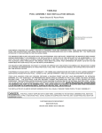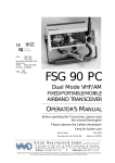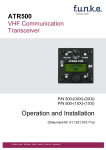
1
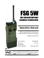
FSG 5W VHF/AM WATERPROOF HANDHELD TRANSCEIVER Operation Manual Before operating the Transceiver, please read this manual thoroughly! Keep for future use! Document No. Article No. 029.HB.04E D10177 Revision No. Date of Revision Dittel Messtechnik GmbH 7 November 2009 Avionics Division Erpftinger Straße 36 86899 Landsberg Germany Telephone +49 (0)8191/ 3351-0 Fax +49 (0)8191/ 3351-49 E-Mail: [email protected] Internet: www.dittel.com Dittel Messtechnik GmbH is certified to DIN EN ISO 9001:2000 and DIN EN ISO 14001:2005. It is an accredited manufacturer of aeronautical equipment DE.21G.0100, maintenance facility DE.145.0245, and development facility ETSO-2C37e/ETSO-2C38e. FSG 5W OPERATION MANUAL SAFETY INFORMATION Every radio, when transmitting, radiates energy into the atmosphere that may, under certain conditions, cause the generation of sparks. All users of our radios should be aware of the following warning: Do not operate radio near flammable liquids or nearby explosive devices. During normal use, the radio will subject you to radio energy substantially below the level where any kind of harm is reported. TO ENSURE PERSONAL SAFETY, please observe the following simple rules: • DO NOT transmit when the antenna is very close to, or touching, exposed parts of the body, especially the face and eyes. • DO NOT transmit inside vehicles or aircraft with the whip antenna, always operate the radio with a suitable external antenna! • DO NOT hold the transmit (PTT) key in when not actually desiring to transmit. • DO NOT allow children to play with any radio equipment containing a transmitter. • DO NOT operate the radio whilst driving. It should also be noticed that the use of a hand held microphone while driving could constitute an offense under the Road Traffic Regulations. • In order to prevent corrosion, the radio should be rinsed with tap-water after use in sea-water. Wipe dry using a clean, lint-free cloth. Nickel-metal hydride Batteries Handling Precaution • Never dispose of Ni-MH batteries in a fire or expose to high temperatures. • Do not connect the positive (+) and negative (-) terminals of Ni-MH batteries together with electrically conductive material, including lead wires. • Do not transport or store Ni-MH batteries with their uncovered terminals. • Do not strike or drop Ni-MH batteries. Sharp impacts or concussion to batteries may result in leakage, heat generation and bursting. • Never disassemble, modify or reconstruct Ni-MH battery packs. • Ni-MH batteries contain a strong colorless alkali liquid. The alkali is extremely corrosive and will cause skin damage. If any liquid from a Ni-MH battery comes in contact with a user's eyes, they should immediately flush their eyes with clean water enough and consult a doctor. The strong alkali can damage eyes and lead to permanent loss of eyesight. Ni-MH This radio contains a Ni-MH battery! DO NOT dispose worn out Ni-MH batteries with domestic waste. Consumers are obliged by law to return Ni-MH batteries at the end of their service lives to the public collecting points set up for this purpose or point of sale. Copyright 2009 Dittel Messtechnik GmbH This document contains proprietary information and such information may not be disclosed to others for any purpose nor used for manufacturing purposes without written permission from: Dittel Messtechnik GmbH, Avionics Division, 86899 Landsberg am Lech, Germany. All rights reserved. The information in this Operation Manual does not profess to include all the details of design, production, or variation of the equipment, or to cover all the possible contingencies which may arise during operation or maintenance. Should any unusual problem arise or further information be desired, please contact the Dittel Messtechnik GmbH Sales Department. Subject to modification 2 Printed in Germany D10177 November 2009 FSG 5W OPERATION MANUAL FSG 5W DIMENSIONS November 2009 D10177 3 FSG 5W OPERATION MANUAL Table of Contents Section 1, General Description ........................................................................................5 1.1 Introduction..............................................................................................................5 1.2 Equipment Description ............................................................................................5 1.3 Modes of Operation .................................................................................................6 1.4 Scope of Delivery ....................................................................................................7 1.5 Optional Accessories...............................................................................................7 Section 2, Charging and Battery Test.................................................................. 9 2.1 2.2 2.3 2.4 Battery Information................................................................................................9 Battery Replacement.............................................................................................9 Battery Test...........................................................................................................9 Recharging the Battery using DL-5A/5W ............................................................ 11 Section 3, Operating Instructions .................................................................................. 13 3.1 3.2 3.3 3.4 3.5 3.6 3.7 3.8 Introduction ......................................................................................................... 13 Preparation for Use ............................................................................................. 13 Operation in the Receive Mode........................................................................... 13 Operation in the Transmit Mode.......................................................................... 14 Switching OFF .................................................................................................... 15 Accessory Socket ............................................................................................... 15 Tips to Obtain Maximum Radio Range ............................................................... 16 Functional Checks .............................................................................................. 16 Section 4, Technical Data ............................................................................................... 17 4.1 General ............................................................................................................... 17 4.2 Receiver.............................................................................................................. 18 4.3 Transmitter.......................................................................................................... 18 Appendix A, CERTIFICATE............................................................................... 19 4 D10177 November 2009 FSG 5W OPERATION MANUAL Section 1 General Description 1.1 Introduction This Operation Manual, 029.HB.04E, contains instructions and descriptions for application and operation of the Dittel’s FSG 5W hand-held VHF AM transceiver with 1,040 operating channels. The Maintenance/Overhaul Manual 029.HB.HB.12 contains a detailed circuit description, repair instructions, alignment procedure, testing instructions, and a detailed Illustrated Parts List. 1.2 Equipment Description The basic model FSG 5W is the heavy-duty water- and dustproof version of the proven self-contained portable hand-held AM transceiver FSG 5 with extended frequency range. It operates throughout the VHF band 118.000 to 143.975 MHz with 25 kHz channel spacing, thus providing 1,040 communication channels in every single unit, being down compatible to ICAO Annex 10. The channel selection is done by turning two knobs (MHz- and kHz-knob) and by reading the frequency display (5 digit liquid crystal display), which are conveniently located on the front cover. A one-Watt transmitter (approx. 3.6 Watt PEP) and a highly sensitive and selective receiver make long-range communication links possible, depending on the location and antenna in use. The ultra low current consumption (e.g. 17 mA drain in standby) makes 15 to 24 hrs of operation with 10% to 5% in transmit mode from one standard battery charge a reality. The solid aluminum case is dust- and waterproof, enabling the transceiver of being used even under rough environmental conditions (-20°C … +60°C/ -4°F…+140°F). Well-selected accessories are available for body-worn, hand-held, portable, mobile and ground station operation even in noisy environment. If desired, dynamic standard or dedicated microphones, headsets, helmet sets, voice operated PTTs and battery chargers can be connected by means of a waterproof general-purpose connector on top of the case. Internal circuits used in the FSG 5W are a combination of high quality components, sophisticated design and new electronics technology. The design of this tiny package was enabled by a high degree of circuit integration (21 integrated circuits versus 14 transistors). Electrically, the FSG 5W consists of nine sections: receiver, transmitter, modulation processor, speaker amplifier, voltage regulator, frequency synthesizer, frequency selector, frequency display, and a battery test circuit. Two coding switches activated by two knobs on the front cover perform the generation of the 12-bit frequency code. One switch generates the megahertz-part of the code (26 steps between stops from 118 to 143 MHz) and the other switch generates the kilohertz-part (40 steps from 000 to 975 kHz). The selected frequency is shown in five digits (e.g., frequency of 135.925 MHz is shown as November 2009 D10177 5 FSG 5W OPERATION MANUAL ‘135.92’) in a liquid crystal display (LCD) on the front cover. The LCD is lighted by LEDs when pressing the ‘LAMP/BATT. TEST’ button on top of the case. The FSG 5W also offers a transmit sidetone output as standard. Receive/sidetone audio volume is adjustable in five steps. Accessory like voice operated PTT keys can be supplied via the accessory socket with switchable 12 VDC from the radio’s battery. 1.3 Modes of Operation The transceiver may be operated in either of two modes; transmit or receive, as selected by the Press-to-Talk (PTT) switch of the transceiver: Transmit Mode - When the built-in or accessory PTT switch is depressed, the transceiver will operate in the transmit mode. Transmission will occur on one of the 1,040 channel frequencies according to the indication of the frequency display, determined by the setting of the two frequency switches. Receive Mode - When the PTT switch on the radio is released, the transceiver will operate in the receive mode. Reception on one of the channel frequencies, as selected by the frequency switches, will occur. The setting of the 'VOL' control determines the audio level produced from the internal loudspeaker and/or the external headphone. When the 'VOL' control is adjusted in the clockwise direction, the audio level will increase. NOTE: In certain operating conditions, an external microphone-loudspeaker, a headset, or a voice operated PTT switch may be connected to the accessory socket of the transceiver. In this case, the PTT switch of the external equipment operates the transceiver via the accessory lead and connector. When the connector of an external microphone or headset is connected to the transceiver accessory socket, the internal loudspeaker and microphone are disconnected and the VOLUME control will control the audio level applied to the external microphone-loudspeaker or headphone, as applicable. Connection of only a headphone (without microphone) does not disable the built-in microphone and loudspeaker. 6 D10177 November 2009 FSG 5W OPERATION MANUAL 1.4 Scope of Delivery VHF/AM hand-held Transceiver FSG 5W, 1,040 channels, frequency range 118.000 MHz to 143.975 MHz, ready for use; including attached battery pack, helical antenna, and Operation Manual. 1.5 Optional Accessories Various audio, control, antenna, and charger accessories allow mobile flight co-ordination and many other demanding applications, besides even specialized operations, like airfield, Search And Rescue, parachute, helicopter winch man, fire fighting, Naval air and/or Army air mission use, consisting of: 10-pole connector to connect customer's accessories to FSG 5W, twist lock, sealed ............................................................................................ F10172 Spare portable helical antenna, 118 … 144 MHz, TNC connector .................E51359 TNC antenna coaxial cable connector, solder type ........................................E08976 DL-5A/5W drop-in automatic 10 hrs automatic Ni-MH battery charger, 115/230 VAC, temperature controlled, continuous/trickle use ........................ F10366 Spare/backup Ni-MH battery 12 V / 1.5 Ah, protected, sealed .......................E51389 Heavy-duty leather carrying case for FSG 5W ..............................................W00005 Additional/spare carrying strap ......................................................................W00023 Microphone-Loudspeaker, fist type, coiled cord, rain proof, 10-pole plug.................................................................................................... F10168 External inline PTT key U-94 A/U, coiled cord, 10-pole plug .......................... F10170 November 2009 D10177 7 FSG 5W OPERATION MANUAL THIS PAGE INTENTIONALLY LEFT BLANK 8 D10177 November 2009 FSG 5W OPERATION MANUAL Section 2 Charging and Battery Test 2.1 Battery Information The Snap-On type battery pack of the radio FSG 5W contains a top quality rechargeable nickel-metal hydride (Ni-MH) battery 12 VDC / 1.5 Ah. It provides sufficient electrical DC power to supply the radio and other connected special accessory. To maintain the battery performance and its cycle service life, the following should be noticed: • Do not discharge battery completely during normal radio operation (no LED indicator ON). • Never store the switched ON radio for more than two days. After such a 100% depth of discharge the Ni-MH battery may not recover during normal recharge. • Self-discharge of battery when not in use (radio switched OFF) is usual and permitted (maximum storage time three years at room temperature). • To prevent Ni-MH batteries from losing capacity, they should be fully discharged and charged cyclically at least once a month (avoids memory effect). • Use only DITTEL Ni-MH battery chargers otherwise you risk to lose the 24 months warranty as well as battery performance/reliability. 2.2 Battery Replacement IMPORTANT! • When removing or replacing the battery pack the handheld transceiver must be turned OFF! • To remove the battery pack (13), take the transceiver into one’s hand and the battery pack in the other. Depress the locking mechanism (12) on both sides of the transceiver's case. Gently pull off the battery pack. • The battery pack is safe against wrong polarity! To replace the battery pack, align battery and radio case and give a push until locking mechanism 'clicks'. Check for proper seat. • Rechargeable DITTEL battery packs can be charged separately or while attached to the radio. • Periodically check the contacts on the bottom of battery pack for dirt that may prevent a good electrical contact with the charging base. • Do not dispose a battery pack in fire. An explosion may occur. DO NOT dispose worn out Ni-MH batteries with domestic waste. Consumers are obliged by law to return Ni-MH batteries at the end of their service lives to the public collecting points set up for this purpose or point of sale. Ni-MH November 2009 D10177 9 FSG 5W OPERATION MANUAL 2.3 Battery Test The battery status should be checked repeatedly/frequently after battery replacement and/or before important missions begin. Disconnect charger or remove radio from drop-in charger before testing, if applicable. Press LAMP/BATT. TEST button (4) for a few seconds. The LED indicators (11) will light up sequentially. 5 LEDs ON: Battery fully charged. 3 to 4 LEDs ON: Battery partially discharged, reduced operating time. 2 or less LEDs ON: Battery discharged (11 VDC or less). STOP using the radio! Charge the battery immediately or replace it by a fully charged battery pack. Release the LAMP/BATT. TEST button. Press LAMP/BATT. TEST button (4), notice LED indicators. Additionally, press the PTT key (9). Almost no change of LEDs indicates a stable/normal battery condition. If indicator varies more than one dot, take care for immediate battery replacement. Release the LAMP/BATT. TEST button. 10 D10177 November 2009 FSG 5W OPERATION MANUAL 2.4 Recharging the Battery using DL-5A/5W (2) (1) (3) The drop-in charger DL-5A/5W is designed for connecting to 115 VAC or 230 VAC, 50 to 60 Hz mains. First of all, check that the unit's operating voltage is identical with your local mains supply. If required, set the voltage selector switch (3) by means of a suitable tool to the respective voltage, changing of fuses is not required. DL-5A/5W is factory set to 230 VAC! Plug the mains cable into a suitable wall outlet. The red pilot lamp (1) lights up. For charging, insert the complete hand-held transceiver FSG 5W or just the removed Ni-MH battery pack upright into the charging chamber. A certain position of the battery pack is not required. If the battery is discharged, the charger switches immediately to rapid charge (yellow lamp (2) lights up). Rapid charge - yellow pilot lamp (2) lights The duration of charge depends on the state of the battery and is approx. 10 hours at 250 mA (for a 1.5 Ah battery).When the switch-off voltage is reached the charger switches automatically to trickle charge. The capacity at the end of rapid charging is about 90% of the full rated capacity. Trickle charge - yellow pilot lamp (2) goes off The Ni-MH battery pack is now continuously charged on low current. The full capacity of the battery is thus guaranteed. Overcharging the battery is not possible due to automatic and temperature controlled charging function, even if the trickle charge is maintained over a long period. Batteries in chargers operating on trickle charge are fully charged. IMPORTANT! • To prevent fire or shock hazard, do not expose the unit to rain or moisture. • To avoid electrical shock, do not open the cabinet. Refer repairing to qualified personnel only. • The chargers must not be operated on or near heaters or in direct sunlight. • Charging should be done within the ambient temperature range of 10°C to +40°C, otherwise the battery may not be fully charged. • The VHF Transceiver FSG 5W with attached battery pack may be operated while being inserted into the drop-in charger, e.g. for temporary fixed base use. • If a fully charged battery is removed briefly from the charger and then reinserted the charging cycle starts again from the beginning: brief rapid charging (yellow LED lights) followed by trickle charge. The NiMH battery incurs no damage. • If the battery is flat it is first recharged on trickle charge until its terminal voltage reaches a certain limit where rapid charging switches on automatically. November 2009 D10177 11 FSG 5W OPERATION MANUAL 12 D10177 November 2009 FSG 5W OPERATION MANUAL Section 3 Operating Instructions 3.1 Introduction A view of the transceiver FSG 5W is given on the last page of this Manual. Please fold out the back flap when reading the operating instructions. Each number of a control, switch, etc. corresponds to the number of the control, switch, etc. given below. 3.2 Preparation for Use To prepare the transceiver for use: • Verify the antenna connection of the helical antenna, or the plug of an external antenna, is tightened. • When using the DITTEL helical antenna, hold the radio so that the antenna shows mainly away from operator's face, head or body, if the radio front (speaker and microphone) is held close to the mouth. Besides reduced RF power impact to the body, a very good antenna radiating efficiency is also obtained for long radio communications distance. • Check proper seat of the battery pack. Ensure Snap-On CLICK. • Rotate the 'VOL' Control (3) clockwise to turn the radio ON. • With the MHz- (7) and kHz switches (8) set the desired operating frequency on the frequency display (6). • Depress the LAMP/BATT. TEST button (4) and check the battery status. • Proceed to Operation in the Receive Mode, paragraph 3.3 or Operation in the Transmit Mode, paragraph 3.4, as appropriate. 3.3 Operation in the Receive Mode To operate the transceiver in the receive mode, proceed as follows: • Ensure that the press-to-talk switch (9) is NOT depressed. • Verify that the display (6) shows your desired operating frequency. • Set the squelch switch (2) to the "SQ" position. • Set the "VOL" Control (3) to a desired audio level. The VOLUME Control can be adjusted in a clockwise direction to increase the audio level, or in a counterclockwise direction to decrease the audio level which can be heard on the internal loudspeaker. IMPORTANT! When an external headset or microphone-loudspeaker is connected to the accessory socket (1) of the transceiver, the internal loudspeaker is not disabled. The 'VOL' Control (3) will now control the audio level of both, the internal and external loudspeaker or headset, as applicable. November 2009 D10177 13 FSG 5W OPERATION MANUAL • On a free channel NO basic receiver noise should be audible in the speaker (Squelch = ON). • To check the receiver's squelch circuit, set squelch switch (2) to 'SQ OFF' position. On a free channel, basic receiver noise with constant volume should be audible (only at an interference free location). • For receiving normal communication, the squelch switch (2) should be in the "SQ" position. Receiver noise, weak signals, and interference signals are blocked, the power consumption of the radio is reduced. • If the squelch switch (2) is set to the 'SQ OFF' position, maximum receiving radio range is obtained and very weak signals can be received satisfactorily, but with noise content. • To change the operating frequency, adjust with MHz- (7) and kHz-switches (8) the desired new frequency readable on the display (6). 3.4 Operation in the Transmit Mode To operate the transceiver in the transmit mode, proceed as follows: • Please, keep radio discipline. The channel must be clear before transmitting. • Verify that the display (6) shows your desired operating frequency. • Hold the transceiver FSG 5W in the left hand, with the microphone area (10) as close as possible to the upper lip. This technique is necessary because the noise cancelling feature of the microphone favors sound close to the microphone and discriminates against sounds away from the microphone. • Depress and hold the press-to-talk (PTT) switch (9) during transmission. • Speak loudly, slowly and distinctly into the built-in microphone (10) from a distance of 3 to 5 cm. • When message is ended, release the PTT switch (9) in order to clear the channel. • The transceiver is now operating in the receive mode. • To change the operating frequency, set with MHz- (7) and kHz-switches (8) your new desired frequency readable on the display (6). During transmit operation a part of the decoupled RF power modulation signal is fed as "Sidetone" to the ear/headphone output of the accessory socket (1). The built-in speaker is switched OFF during transmitting. Therefore sidetone is only audible when the radio FSG 5W is operated with an ear/headphone. Transmit sidetone audio volume corresponds with the receive volume setting of the transceiver. IMPORTANT! The transmitter output amplifier is protected against any antenna mismatch by a directional coupler circuit. Transmitting without any antenna will therefore not harm the output amplifier. Significant antenna mismatch will reduce dramatically the range of transmission. 14 D10177 November 2009 FSG 5W OPERATION MANUAL 3.5 Switching OFF To switch off the transceiver: Turn the "VOL" rotary switch (3) to the OFF position. IMPORTANT! In order to prevent corrosion, the radio should be rinsed with tap-water after use in sea-water. Wipe dry using a clean, lint-free cloth. 3.6 Accessory Socket The sealed 10pole twist lock accessory socket (1) allows connection of accessories for various applications and operating conditions. • When an external dynamic microphone with a d.c. impedance of less than 200 Ohms is connected, the built-in microphone is automatically switched OFF. Otherwise both the external and internal microphones are active. • An external power supply (12 VDC from car or aircraft supply, negative ground) or a battery charger may also connected via socket (1). Even the 12 VDC supply of external accessories like our VOX 90 is possible (then the FSG 5W must be switched ON) • In noisy environment a second loudspeaker or a noise cancelling headphone is recommended. The impedance of it shall be at least 30 Ohms at maximum audio level setting. For certain applications two headsets can be operated in parallel. • Always recap accessory socket when not in use! Pin assignment: A: Earphone/headphone/loudspeaker, at least 30 Ohms (to 8 Ohms permitted); B: GND (power, PTT, AF); C: Ext. microphone 5 … 200 Ohms; D: Not connected; E: Not connected; F: External PTT key (common return via contact B); G: Microphone GND; H: +11.7 to +15.1 VDC: 1) Input to charge the battery 2) 12 V-Output to supply VOX 90 or other accessories (FSG 5W must be switched ON) 3) Supply from 12 VDC car or aircraft J: Not connected; K: Not connected; November 2009 D10177 15 FSG 5W OPERATION MANUAL 3.7 Tips to obtain Maximum Radio Range For best results when operating in the open field an all-round obstacle free location and a vertically hold antenna are the most important requirements. The receiving/ transmitting range will be reduced partly − when the radio is operated within, or nearby large metal structures, − when the own body or persons very close are screening the antenna, − when mayor obstacles exist between the transceiver and the station being called, like aircraft, vehicles, buildings, mountains, etc. − when strong high frequency sources like ignition systems or electromotors are nearby. Never transmit without an antenna! Make sure, external antenna is DC grounded! Obtain a geographic line of sight location to 'see' the station called! When using the transceiver in buildings, vehicles or aircraft, the radio should always be operated on a suitable external antenna. CAUTION: During Transmit mode, keep antenna radiator tip at least 10 cm away from head or skin of the body! Hold antenna neither close to your skin, eyes, other electronic equipment, nor touch it! 3.8 Functional Checks When the transceiver FSG 5W does not operate correctly, check the following: • Is desired operational frequency adjusted? • Carry out a battery test without any charger or external supply connected. • Switch OFF squelch when receiving weak signals. • Operate radio without any accessory. Same malfunction? • Is helical antenna or antenna plug/cable damaged? • Is voice level too low or distance to microphone too far? • Does multipath effect occur? Change location. • In case of doubt, compare operation of the transceiver with that of another transceiver FSG 5/FSG 5W at the same location. • Should the unit require service, contact your authorized dealer or service department. 16 D10177 November 2009 FSG 5W OPERATION MANUAL Section 4 Technical Data 4.1 General Dimensions : 232 mm × 87.5 mm × 54 mm (without antenna) Weight : 1,100 g including battery and helical antenna Frequency range : 118.000 … 143.975 MHz / 1,040 channels, directly switchable Channel spacing : 25 kHz Modulation : AM 6A3 Modulation frequency 350 Hz ... 2,500 Hz Supply voltage : 11.0 … 14.4 VDC internal 11.7 … 15.1 VDC external Internal battery : Ni-MH 12 VDC / 1,500 mAh nominal, detachable Battery operating time : 9 hours to 45 hours, depends on operating mode Current consumption : Transmit - 550 mA or less Receive - 150 mA ± 20 mA at 0.5 W AF power Standby - 17 mA ± 3 mA Antenna impedance : 50 Ohm Antenna Jack : TNC, flexible Helix Antenna Operating temperature range : -20°C … +60°C / -4°F … +140°F Charging temperature range : 0°C … +40°C / +32°F … +104°F Submersible (helical antenna and battery pack must be attached) : Fulfills EN 60 529, Class IP X7 1.0 m (3 ft) for 30 minutes, additional tested to: 3.0 m (10 ft) for 30 seconds IMPORTANT! • In order to prevent corrosion, the radio should be rinsed with tap water after use in seawater. Wipe dry using a clean, lint-free cloth. November 2009 D10177 17 FSG 5W OPERATION MANUAL 4.2 Receiver Sensitivity : 1 µV / 50 Ω or less for 6 dB S+N/N, 1 kHz/m = 30% Squelch : AM/Pulse combined, automatic, defeatable, threshold internally adjustable Selectivity : 6 dB or less at ± 8 kHz 40 dB or more at ± 17 kHz 60 dB or more at ± 25 kHz Radiated Interference : at least 64 dBm down (50 Ohm) Modulation AF Response 4.3 AF output : 0.5 Watt or more into built-in 8 Ohm speaker @ 12 VBatt Headphone output : 2 VRMS or more into at least 30 Ohms Transmitter Power output @ 12 VBatt : 1 Watt (-0.2 W / +0.3 W) carrier into 50 Ohms (ca. 3.6 W PEP) Frequency Stability : ± 10 ppm (± 1.5 kHz) or better at -20°C to +60°C Spurious / Harmonic Radiation : - 60 dBc or less Adjacent Channel Suppression : at least -70 dB: 1,250 Hz, m = 60% + 10 dB (± 25 kHz) Modulation type : 6A3 (AM) Modulation depth : Typical 75% @ 12 VBatt, (max 95%) Distortion Factor : 10% or less @ 1 kHz / m = 70% Built-in microphone : Electret type Microphone Level : 1 mV … 10 mV Suitable external microphone 18 6 dB or less @ 350 … 2,500 Hz : Dynamic microphone 5 … 200 Ohms/ ≥ 1.5 mV. Connection of an external microphone disables the internal microphone. D10177 November 2009 FSG 5W OPERATION MANUAL Appendix A Certificate November 2009 D10177 19 FSG 5W OPERATION MANUAL THIS PAGE INTENTIONALLY LEFT BLANK 20 D10177 November 2009 FSG 5W OPERATION MANUAL FSG 5W Operator's switches, controls and indicators November 2009 D10177 21