1
Owner’s Manual
Model Numbers
AHE-100-02S -12 VDC
AHE-200-02S - 24 VDC
Aqua-Hot™ Motor Coach Heating System Owner's Manual 05/02
OWNER’S INFORMATION
Owner’s Name:
Address:
CUT HERE AND MAIL IN
City:
State:
Zip Code:
Telephone:
Coach Model:
Coach Date of Purchase:
Aqua-Hot Model No:
Aqua-Hot Serial No:
Please Mail To:
Vehicle Systems Warranty Department
15549 East Highway 52
Ft. Lupton, CO 80621
Aqua-Hot™ Motor Coach Heating System Owner's Manual 05/02
Vehicle Systems, Inc.
Warranty Department
15549 East Highway 52
Ft. Lupton, CO 80621
Aqua-Hot™ Motor Coach Heating System Owner's Manual 05/02
TABLE OF CONTENTS
1.0
Overview
2.0
Operating Instructions
2.1
Activating the Aqua-Hot Heating System
2.2
Zone Thermostat(s) Operation
2.3
Using the Domestic Hot Water System
2.4
Using the Engine Preheat System
2.5
Diesel-Burner Operational Flow-Chart
2.6
Precautions
3.0
Maintenance
3.1
Maintenance Schedule
4.0
Winterization
4.1
Domestic Hot Water System
5.0
Troubleshooting
Aqua-Hot™ Motor Coach Heating System Owner's Manual 05/02
SECTION 1: OVERVIEW
Aqua-Hot
Overview
Page 1-1
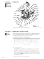
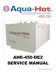
The Aqua-Hot Motor Coach Heating System is an on-board Hydronic Heating
System (heating with hot water) that provides a continuous, on-demand
supply of domestic hot water, as well as interior zone heating where and when
it is needed. Both heating features are accomplished by a unique Diesel-Fired
Burner and an AC powered Electric Heating Element (120 VAC). These two
heating sources maintain the temperature of the Aqua-Hot's solution of water
and antifreeze. In addition, the Aqua-Hot has been designed to preheat the
vehicle's engine prior to starting. This feature provides easy engine start-up
whenever cool weather conditions are present. Be sure to review Figure 1
for complete component overview.
Aqua-Hot™ Motor Coach Heating System Owner's Manual 05/02
SECTION 1: OVERVIEW
Ho
t
Aqua-Hot
Overview,
continued
Expansion
Tank
Fill / Radiator
Cap
Co
ld
Zone A
Supply
Thermostat
Access Panel
Zone A
Return
Zone B
Return
Zone B
Supply
VAC Service
Input
Zone C
Return
Terminal
Board
Zone C
Supply
VAC Access
Panel
Zone
Circulation
Pump
Fuse Block
Engine Preheat
Circulation
Pump
I.D Plates
Zone Relay #A
Diesel-Burner
Head
Zone Relay #B
Engine Coolant
Supply
Zone Relay #C
Electric Heating
Element Access
Panel
Diesel Fuel
Supply
Diesel Fuel
Return
Engine
Coolant
Return
Diesel-Burner
Control
Unit
Mixer
Valve
Pressure-Relief
Cold Water
Valve
Inlet
Hot Water
(Domestic
Water)
Outlet
(Domestic Water)
Aqua-Hot™ Motor Coach Heating System Owner's Manual 05/02
Figure 1
Page 1-2
SECTION 2: OPERATING INSTRUCTIONS
Heat
Source
Please read the complete Owner’s Manual prior to operating your AquaHot Heating System. Also, be sure to fill out and mail in your Owner’s
Information Card located at the front of this manual.
2.1 Activating The Aqua-Hot Heating System
Diesel-Burner
Turn the Diesel-Burner Control Switch ON. This procedure will activate
the Diesel-Burner and the indicator light located on or near the Switch.
Please contact your specific motorhome manufacturer for the exact
Diesel-Burner Control Switch location. Allow 10-20 minutes for the System to reach operating temperature. Please note that the Diesel-Burner is
the main heat source for heating both the interior and the domestic hot
water. So, be sure to leave this switch ON during normal heating requirements.
Electric Heating Element
The VAC Electric Heating Element is wired directly into your motorhomes
120 VAC electrical system and is operational whenever VAC power is
available. Allow 1-2 hours for the System to reach operating temperature.
Please note that the Electric Heating Element will adaquately provide all
your heating needs only for low heating demand situations, such as when
moderate ambient temperatures exist and/or when there is a low demand
for domestic hot water.
Page 2-1
Aqua-Hot™ Motor Coach Heating System Owner's Manual 05/02
SECTION 2: OPERATING INSTRUCTIONS
Heat
Source,
continued
NOTE: Both the Diesel-Burner and the 120 VAC Electric Heating Element
are thermostatically controlled. Either, or both, heating sources will
automatically maintain the temperature of the Aqua-Hot's water and
antifreeze solution between approximately 175-200 degrees Fahrenheit.
So simply choose how you want to heat your coach/hot water and just
leave the Switch(s) (Diesel, Electric, or both) ON.
Comfort
Control
2.2 Zone Thermostat(s) Operation
Interior Room Thermostats
Simply adjust each Room Thermostat to the desired temperature. Then
whenever a Room Thermostat “calls-for-heat” the Aqua-Hot’s Circulation
Pump(s) and Interior Zone Fans will be activated. These devices together
will supply warmth and comfort to each interior heating zone. Please
contact your specific motorhome manufacturer for the exact Room
Thermostat location(s).
Bay Thermostat
Simply adjust the Bay Thermostat to approximately 40 degrees
Fahrenheit. This will prevent freezing of the domestic water storage
system. Please contact your specific motorhome manufacturer for the
exact Bay Thermostat location.
Aqua-Hot™ Motor Coach Heating System Owner's Manual 05/02
Page 2-2
SECTION 2: OPERATING INSTRUCTIONS
Hot Water
2.3 Using the Domestic Hot Water System
When the Aqua-Hot is at operating temperature, the domestic water is
automatically heated as it is being used. Because the Aqua-Hot does not
store any hot water simply open any hot water faucet and a continuous
supply of domestic hot water will be present within a few seconds. This hot
water feature is continuous and is accomplished by the Aqua-Hot’s Mixer
Valve and Intergal Domestic Hot Water Heating System. Please note that
the Diesel-Burner Control Switch must be ON to get an unlimited supply of
hot water (i.e. during showers).
Engine
Preheat
2.4 Using the Engine Preheat System
When the Aqua-Hot is at operating temperature, and the Diesel-Burner
and/or the 120 VAC Electric Heating Element Switch(s) is ON, follow
these simple instructions:
A. Turn the Aqua-Hot's Engine Preheat Switch ON. This procedure will
activate the Engine Preheat Circulation Pump. Circulating the engine's
coolant through the Engine Preheat System will adequately warm the
engine for easy start-ups on cool mornings. Please contact your specific
motorhome manufacturer for the exact Engine Preheat Switch location.
NOTE: Allow approximately 1 to 2 hours of engine preheating run time.
Time will be shortest when the Diesel-Burner Control Switch is ON.
Page 2-3
Aqua-Hot™ Motor Coach Heating System Owner's Manual 05/02
SECTION 2: OPERATING INSTRUCTIONS
Engine
Preheat,
continued
B. Turn OFF the Aqua-Hot's Engine Preheat Switch whenever engine
preheating is not desired.
NOTE: The Aqua-Hot's Engine Preheating System acts as a supplemental heating source, in addition to the Diesel-Burner and the 120
VAC Electric Heating Element. While traveling, the engine's heated
coolant will automatically pass through the Engine Preheat / Motoraide
System, transferring heat into the Aqua-Hot's Heat Tank. This design
feature reduces the total operating hours of the Diesel-Burner and the
120 VAC Electric Heating Element.
Aqua-Hot™ Motor Coach Heating System Owner's Manual 05/02
Page 2-4
SECTION 2: OPERATING INSTRUCTIONS
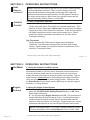
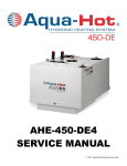
DieselBurner
Component
Overview
1.
2.
3.
4.
5.
6.
7.
8.
9.
Control Unit
Motor
Ignition Coil
Clutch
Combustion Air Fan
Fuel Solenoid Valve
Electrode Holder
Ignition Electrodes
Fuel Nozzle
Figure 2
Page 2-5
Aqua-Hot™ Motor Coach Heating System Owner's Manual 05/02
10.
11.
12.
13.
14.
15.
16.
Combustion Chamber
Heat Exchanger
Exhaust Port
Flame Detection Photocell
Fuel Pump
Fuel Ports (Supply / Return)
Combustion Air Port (Intake)
with Adjustable Shutter
SECTION 2: OPERATING INSTRUCTIONS
DieselBurner
Operational
Flow-Chart
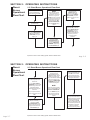
2.5 Diesel-Burner Operational Flow-Chart
Operation sequence once the
Aqua-Hot's Diesel-Burner
Control Switch is turned ON.
The Control Switch's indicator
light will illuminate.
NOTE:
If the Aqua-Hot's Coolant
reservoir temperature is
approximately 175 degrees
Fahrenheit, or higher, the
"MOTOR" (#2) will not operate.
Only when the temperature has
dropped below 175 degrees
Fahrenheit will the "VDC
CONTROL THERMOSTAT"
allow the "MOTOR" (#2) to
operate.
Simultaneously the
"IGNITION COIL" (#3)
produces a High Voltage
Spark across the "IGNITION
ELECTRODES" (#8) which
ignites the incoming Air / Fuel
mixture.
Once the ignited Air / Fuel
mixture (FLAME) is observed
by the "FLAME DETECTION
PHOTOCELL" (#13), the
"IGNITION COIL" (#3) will
automatically switch OFF. The
combustion process now
continues to operate
unassisted.
The "MOTOR" (#2) (which
turns the "COMBUSTION AIR
FAN" (#5) and drives the
"FUEL PUMP" (#14)) will
begin to run.
After approximately 10 - 25
seconds the "FUEL
SOLENOID VALVE" (#6)
opens and fuel is sprayed
into the "COMBUSTION
CHAMBER" (#10) through
the "FUEL NOZZLE" (#9).
Aqua-Hot™ Motor Coach Heating System Owner's Manual 05/02
Page 2-6
SECTION 2: OPERATING INSTRUCTIONS
DieselBurner
Operational
Flow-Chart
2.5 Diesel-Burner Operational Flow-Chart
The combustion process will
continue to operate in this
manner until:
A.) The "VDC CONTROL
THERMOSTAT", (which senses
Coolant Temp.), reaches the
preset temperature of
approximately 190 degrees
Fahrenheit.
B.) The Aqua-Hot's DieselBurner Control Switch is turned
OFF.
The "MOTOR" (#2) will
continue to run for
approximately three (3)
additional minutes. This is
called the "Purge-Cycle",
which cools down the Heater's
internal components and
purges the "COMBUSTION
CHAMBER" (#10) of any
residual exhaust gases.
NOTE:
When the Aqua-Hot's DieselBurner is switched OFF by the
"CONTROL THERMOSTAT".
A.) The "MOTOR" (#2) will
shut-off once the three (3)
minute "Purge-Cycle" has
expired.
Once the Heater switches
OFF, thermostatically or
manually, the "FUEL
SOLENOID VALVE" (#6)
closes, which interrupts the
supply of diesel fuel to the
"FUEL NOZZLE" (#9).
Page 2-7
B.) The Aqua-Hot's DieselBurner will automatically turn
back ON once the coolant
temp. reaches the preset
temperature of approximately
175 degrees Fahrenheit.
Aqua-Hot™ Motor Coach Heating System Owner's Manual 05/02
SUMMARY:
The Aqua-Hot's Diesel-Burner is
operational anytime the operator
activates the Diesel-Burner
Control Switch to the ON
position. The Diesel-Burner will
then automatically maintain the
temperature of the coolant
without any additional
involvement from the operator.
SECTION 2: OPERATING INSTRUCTIONS
Important
Information
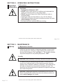
2.6 Precautions
CAUTIONS:
• The Aqua-Hot's Exhaust is HOT!
• DO NOT park in areas where dry conditions exist underneath the
vehicle, as a fire may result (i.e. dry grassy fields) .
• DO NOT operate the Aqua-Hot’s Diesel-Fired Burner inside an
enclosed building.
• Operating the Aqua-Hot Diesel-Burner or the 120 VAC Electric
Heating Element without the water and antifreeze solution will cause
serious damage to the Heater.
• The Heater should be switched OFF when refueling.
Aqua-Hot™ Motor Coach Heating System Owner's Manual 05/02
Page 2-8
SECTION 3: MAINTENANCE
Upkeep
3.1 Maintenance Schedule
Monthly
Check the Aqua-Hot's solution of water and antifreeze to ensure that it
is at the proper level. Do this by visually checking the coolant level in
the Aqua-Hot's Expansion Tank, see Figure 1. This should be checked
only when the Aqua-Hot is at operating temperature, “HOT.”
Annually
CAUTION: Before cleaning or servicing, disconnect all power supplies.
It is ideal to have your Aqua-Hot tuned-up yearly. A tune-up should
consist of a Fuel Nozzle and Fuel Filter replacement and a thorough
cleaning of the Combustion Chamber, if necessary. This simple tune-up
will keep your Aqua-Hot running smoothly throughout the year. This
annual tune-up will also allow service personnel to inspect for wear and
tear of other components.
CAUTION: Operating the Aqua-Hot’s Diesel-Burner or the 120 VAC
Electric Heating Element without the water and antifreeze solution will
cause serious damage to the Heater.
Page 3-1
Aqua-Hot™ Motor Coach Heating System Owner's Manual 05/02
SECTION 4: WINTERIZATION
Storage
4.1 Domestic Hot Water System
The Aqua-Hot's domestic hot water system must be completely drained of
domestic water any time the heater is stored where freezing temperatures
may be experienced.
CAUTION: Not winterizing your Aqua-Hot, when freezing temperatures
are present, will result in serious damage to the Aqua-Hot's domestic
hot water system.
NOTE: The Aqua-Hot can still be used for interior zone heating even if the
domestic hot water system has been drained and winterized.
Follow the instructions listed below when winterizing the Aqua-Hot’s
domestic water system:
A. Completely drain the fresh water storage tank.
NOTE: If your coach is equipped with appliances that use fresh water (i.e.
ice makers, water purifiers, etc.) follow the manufacturer's
recommendation for winterization.
B. Disconnect the domestic water demand pump's suction line from the
fresh water storage tank.
C. Attach an adequate piece of hose onto the suction side of the domestic
water demand pump.
D. Place the opposite end of the hose into an adequate supply of FDA
approved RV-Antifreeze; approximately 2 gallons will be required.
Aqua-Hot™ Motor Coach Heating System Owner's Manual 05/02
Page 4-1
SECTION 4: WINTERIZATION
Storage,
continued
E. Open/close all interior and exterior water faucets, one at a time, until only
pure RV-Antifreeze is present. Perform this procedure for both hot and cold
faucets.
F. Remove the hose and reconnect the domestic water demand pump's
suction line to the fresh water storage tank.
G. Disconnect all electrical power supplies to the Aqua-Hot during storage.
NOTE: 1. For de-winterization, fill the fresh water storage tank with fresh
water. Open/close all interior and exterior water faucets, one at a time, until
only clear water is present/visible.
CAUTION: If you’re disinfecting your potable water system, after de-winterizing, be sure to follow RVIA’s “Instruction for Disinfection of Potable Water
Systems on Recreation Vehicles.” These instructions can be found in the
ANSI A119.2 Handbook for Recreational Vehicle Standards. To receive a
copy of this RVIA Standard, write to: Recreation Vehicle Industry Association, 1896 Preston White Drive, P.O. Box 2999, Reston, VA 20195-0999, or
visit the RVIA website at www.rvia.com.
Page 4-2
Aqua-Hot™ Motor Coach Heating System Owner's Manual 05/02
SECTION 5: TROUBLESHOOTING
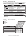
Prior to troubleshooting your Aqua-Hot, be sure to reference Figure 1 for a complete overview of the
heating system, and Figure 2 for a complete component overview of the Diesel-Burner. Also, please
review Section 2.5 of this manual for details on the Diesel-Burner’s operation. Use the following
chart when troubleshooting your Diesel-Burner only.
Failure Symptom
Probable Cause
Remedy
No Indicator Light on the
Diesel-Burner Control Switch or
Indicator Light goes Off after 30
sec.
Diesel-Burner Control Switch is
On, but the Diesel-Burner’s
Motor does not function, see
Figure 2.
Less than 10 Volts DC to the Aqua-Hot.
No Fuel to the Diesel-Burner.
Defective Fuel Nozzle.
Defective Indicator Light Bulb.
Check House Batteries and Charging System.
Check Fuel Filter and Fuel System.
Replace Fuel Nozzle.
Replace Indicator Light Bulb.
Loose Harness Plug Connections at the Control Unit.
Open “E” or “F” Fuse at the Aqua-Hot.
Less than 10 Volts DC to the Aqua-Hot.
Defective Diesel-Burner Control Switch or Loose Conn.
Check Harness Plug Connections to be secure and in
place on the underside of the Control Unit.
Replace “E” or “F” Fuse.
Check House Batteries and Charging System.
Replace Switch or Repair Loose Connection.
Diesel-Burner does not respond
with the 10-25 sec. Purge-cycle
Diesel-Burner’s Combustion
Process does not take place.
Less than 10 Volts DC to the Aqua-Hot.
Check House Batteries and Charging System.
Loose Harness Plug Connections at the Control Unit.
Check Harness Plug Connections to be secure and in
place on the underside of the Control Unit.
Replace “E” or “F” Fuse.
Check Fuel Filter and Fuel System.
Replace Fuel Nozzle.
Check Harness Plug Connections to be secure and in
place on the underside of the Control Unit.
Check House Batteries and Charging System.
Open “E” or “F” Fuse at the Aqua-Hot.
No Fuel to the Diesel-Burner.
Defective Fuel Nozzle.
Loose Harness Plug Connections at the Control Unit.
Diesel-Burner’s Combustion
Process stops after 30 sec.
Less than 10 Volts DC to the Aqua-Hot.
Use the following chart when troubleshooting your 120 VAC Electric Heating Element only.
120 VAC Electric Heating
Element does not produce heat,
or hot water, when motorhome
is plugged into shore power.
VAC Breaker is Off or Switch is Defective.
Turn VAC Breaker On or replace Switch.
Aqua-Hot™ Motor Coach Heating System Owner's Manual 05/02
Page 5-1
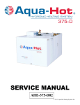
SECTION 5: TROUBLESHOOTING
Aqua-Hot
Quick
Reference
Chart
No Function
Diesel Control Switch Indicator Light
Engine Preheat Control Switch
No indicator light
Motor is not operating
Diesel-Burner
No 10-25 second prime cycle
Diesel-Burner
Ignition Coil will not spark
Diesel-Burner
No Combustion
Diesel-Burner
Combustion stops after 30 seconds
120 VAC Heating Element
Page 5-2
No indicator light or "Off" after 30 sec.
Diesel-Burner
Engine Preheat
Di
FAILURE SYMPTOM
COMPONENTS
Diesel Control Switch "On"
es
el
Sw Con
tro
itc
lS
hI
wi
nd
Aq
tch
ica
ua
to
-H
r
o
VD
L
t
igh
("
CV
tB
olt E" &
ulb
ag
VD
"
F"
eL
CW
)F
e
us
ve
iri
VA
es
l to
ng
,C
C
a
Aq
Ci
on
ua
rcu nd B
tin
En
uit
H
it B
Pl
o
gin
y?
ug
t
re
eP
Ha
ak
Aq
re
e
r
n
r
ua
he
es
-H
at
sC
ot
Fu
on
("A Con
el
n.
t
ro
")
Su
lS
Fu
pp
Fu
wi
s
l
y
e
el
tch
s,
(N
No
Co
oF
zz
Di
nt
ue
le
es
inu
lo
elity
ra
Bu
?
ir
rn
lea
er
k)
CPl
ug
Ha
rn
es
sC
on
n.
CHECK OR REPLACE IF NECESSARY
No heat / hot water when plugged into shore power
Diesel Engine Remains cold
Aqua-Hot™ Motor Coach Heating System Owner's Manual 05/02
WARRANTY POLICY
- FOR AQUA-HOT MODELS Vehicle Systems Inc. warrants the AQUA-HOT Heater, to the original owner, to be free from defects
in material and workmanship under design usage and service conditions for a period of two (2)
years on parts and labor beginning on the date of purchase of the vehicle. Replacement parts are
covered for the remainder of the heating systems warranty or for six months (180 days) which ever
is greater.
This warranty does not apply to damage or failure of the AQUA-HOT Heater or the vehicle
into which it was installed due to improper installation, assembly, maintenance, abuse,
neglect, accident, or the use of parts not supplied by Vehicle Systems Inc. Vehicle Systems
is not responsible for incidental or consequential damages.
The intent of this warranty is to protect the end user of the heating system from such defects, which
would occur in the manufacture of the product. The warranty is not intended to protect the end
user from problems, which are outside the ability of Vehicle Systems’ control.
To obtain warranty repair authorization or for additional information please contact our Technical
Support Department at 1-800-685-4298 (8 AM to 5 PM) Mountain Standard Time.
Aqua-Hot™ Motor Coach Heating System Owner's Manual 05/02
OWNER’S SERVICE LOG:
Date
Scheduled Service
Service Center
Aqua-Hot™ Motor Coach Heating System Owner's Manual 05/02
(Continued)
Date
OWNER’S SERVICE LOG:
Scheduled Service
Service Center
Aqua-Hot™ Motor Coach Heating System Owner's Manual 05/02
(Continued)
Date
OWNER’S SERVICE LOG:
Scheduled Service
Service Center
Aqua-Hot™ Motor Coach Heating System Owner's Manual 05/02
Aqua-Hot™ Motor Coach Heating System Owner's Manual 05/02
Motor Coach Heating Specialists · Manufacturers and Distributors
15549 East Highway 52 • Fort Lupton, Colorado 80621 • 1-800-685-4298 • Fax: 303-857-9000
Copyright 2002 Vehicle Systems, Inc. All rights reserved
www.aqua-hot.com
Aqua-Hot™ Motor Coach
Heating System Owner's Manual 05/02
LTE-LMA-002