1
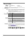
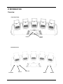
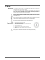
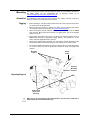
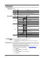
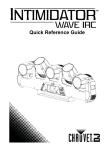
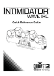
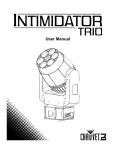
User Manual
TABLE OF CONTENTS
1. Before You Begin .......................................................................................................... 4
What Is Included ............................................................................................................................... 4
Unpacking Instructions ..................................................................................................................... 4
Claims ....................................................................................................................................................... 4
Text Conventions ............................................................................................................................. 4
Symbols ............................................................................................................................................ 4
Disclaimer ......................................................................................................................................... 4
Product at a Glance .......................................................................................................................... 5
Safety Notes ..................................................................................................................................... 5
2. Introduction ................................................................................................................... 6
Overview........................................................................................................................................... 6
Dimensions ....................................................................................................................................... 7
3. Setup .............................................................................................................................. 8
AC Power ......................................................................................................................................... 8
Fuse Replacement ................................................................................................................................... 8
Power Linking ............................................................................................................................................ 9
Mounting ......................................................................................................................................... 10
Orientation ............................................................................................................................................... 10
Rigging .................................................................................................................................................... 10
4. Operation ......................................................................................................................11
Control Panel Operation ................................................................................................................. 11
Menu Map....................................................................................................................................... 11
Configuration (DMX) ....................................................................................................................... 11
Starting Address ...................................................................................................................................... 11
DMX Personalities ................................................................................................................................... 12
Master Auto ............................................................................................................................................. 12
4-Head Program ...................................................................................................................................... 12
Master Auto ............................................................................................................................................. 13
2-Head Program ...................................................................................................................................... 13
Master Auto ............................................................................................................................................. 13
1-Head Program ...................................................................................................................................... 13
DMX Assignments ............................................................................................................14
34CH .............................................................................................................................................. 14
DMX Assignments (Cont.) ...............................................................................................15
34CH .............................................................................................................................................. 15
DMX Assignments (Cont.) ...............................................................................................16
34CH .............................................................................................................................................. 16
DMX Assignments (Cont.) ...............................................................................................17
34CH .............................................................................................................................................. 17
DMX Assignments (Cont.) ...............................................................................................18
34CH .............................................................................................................................................. 18
DMX Assignments (Cont.) ...............................................................................................19
34CH .............................................................................................................................................. 19
DMX Assignments (Cont.) ...............................................................................................20
34CH .............................................................................................................................................. 20
DMX Assignments (Cont.) ...............................................................................................21
14CH .............................................................................................................................................. 21
DMX Assignments (Cont.) ...............................................................................................22
Page 2 of 32
Intimidator™ Wave IRC User Manual Rev. 1
14CH .............................................................................................................................................. 22
DMX Assignments (Cont.) ...............................................................................................23
14CH .............................................................................................................................................. 23
DMX Assignments (Cont.) ...............................................................................................24
14CH .............................................................................................................................................. 24
DMX Assignments (Cont.) ...............................................................................................25
14CH .............................................................................................................................................. 25
DMX Assignments (Cont.) ...............................................................................................26
14CH .............................................................................................................................................. 26
Configuration (Standalone) ............................................................................................................ 27
Sound-Active Mode ................................................................................................................................. 27
Automatic Mode....................................................................................................................................... 27
Manual Reverse Tilt Operation ................................................................................................................ 27
Manual Tilt Angle Range ......................................................................................................................... 27
Display Blackout and Reverse ................................................................................................................. 28
Master/Slave Mode .................................................................................................................................. 28
Reset Software ............................................................................................................................... 28
Factory Defaults ............................................................................................................................. 28
5. Technical Information ..................................................................................................29
Product Maintenance ..................................................................................................................... 29
6. Technical Specifications..............................................................................................30
Returns .............................................................................................................................31
Contact Us ........................................................................................................................32
Intimidator™ Wave IRC User Manual Rev. 1
Page 3 of 32
1. BEFORE YOU BEGIN
What Is
Included
·
·
Intimidator™ Wave IRC
Hanging bracket with mounting
hardware
·
·
·
Power cord
Warranty card
Quick Reference Guide
Unpacking
Instructions
Carefully unpack the product immediately and check the container to make sure all the
parts are in the package and are in good condition.
Claims
If the box or the contents (the product and included accessories) appear damaged from
shipping, or show signs of mishandling, notify the carrier immediately, not Chauvet
Failure to report damage to the carrier immediately may invalidate your claim. In
addition, keep the box and contents for inspection.
For other issues, such as missing components or parts, damage not related to shipping,
or concealed damage, file a claim with Chauvet within 7 days of delivery.
Text
Conventions
Symbols
Convention
1–512
50/60
Settings
Menu > Settings
<ENTER>
ON
Symbol
Meaning
A range of values
A set of values of which only one can be chosen
A menu option not to be modified
A sequence of menu options to be followed
A key to be pressed on the product’s control panel
A value to be entered or selected
Meaning
Critical installation, configuration, or operation information. Not
following these instructions may make the product not work, cause
damage to the product, or cause harm to the operator.
Important installation or configuration information. The product
may not function correctly if this information is not used.
Useful information.
Disclaimer
The information and specifications contained in this User Manual are subject to change
without notice. Chauvet assumes no responsibility or liability for any errors or omissions,
and reserves the right to revise or recreate this manual at any time. Download the latest
version from www.chauvetlighting.com.
© Copyright 2014 Chauvet All rights reserved.
Electronically published by Chauvet in the United States of America.
Page 4 of 32
Author
Date
Editor
Date
M. Trouard
10/17/2014
A. Leon
11/3/14
Intimidator™ Wave IRC User Manual Rev. 1
Product at a
Glance
Use on Dimmer
Outdoor Use
Sound-Activated
DMX
Master/Slave
Safety Notes
x
x
P
P
P
Auto Programs
Auto-ranging Power Supply
Replaceable Fuse
User-Serviceable
P
P
P
x
These notes include important information about the mounting, usage, and maintenance
of this product; read before using the product.
·
·
·
·
·
·
·
·
·
·
·
·
·
·
·
·
·
·
·
·
Always connect the product to a grounded circuit to avoid the risk of electrocution.
Always disconnect the product from the power source before cleaning or replacing
the fuse.
Avoid direct eye exposure to the light source while the product is on.
Make sure the power cord is not crimped or damaged.
Never disconnect the product from power by pulling or tugging on the cord.
If mounting the product overhead, always secure to a fastening device using a
safety cable.
Make sure there are no flammable materials close to the product when operating.
Do not touch the product’s housing when operating because it may be very hot.
Always make sure that the voltage of the outlet to which you are connecting the
product is within the range stated on the decal or rear panel of the product.
The product is for indoor use only! (IP20) To prevent risk of fire or shock, do not
expose the product to rain or moisture.
Always install the product in a location with adequate ventilation, at least 20 in
(50 cm) from adjacent surfaces.
Be sure that no ventilation slots on the product’s housing are blocked.
Never connect the product to a dimmer.
Make sure to replace the fuse with another of the same type and rating.
Never carry the product from the power cord or any moving part. Always use the
hanging/mounting bracket or the handles.
The maximum ambient temperature (Ta) is 104 °F (40 °C). Do not operate the
product at higher temperatures.
In the event of a serious operating problem, stop using the product immediately.
Never try to repair the product. Repairs carried out by unskilled people can lead to
damage or malfunction. Contact the nearest authorized technical assistance center.
This product is not intended for permanent installation.
To eliminate unnecessary wear and improve its lifespan, during periods of non-use
completely disconnect the product from the power via breaker or by unplugging it.
Keep this User Manual for future use. If you sell the product to another user, be sure to
give this document to the next owner.
Intimidator™ Wave IRC User Manual Rev. 1
Page 5 of 32
2. INTRODUCTION
Overview
Front Panel View
Head
2
Head
1
Display
Head
3
Head
4
Head
5
Control
Buttons
Back Panel View
Fuse Holder
Page 6 of 32
Power In
Power Out
DMX In
DMX Out
Intimidator™ Wave IRC User Manual Rev. 1
Dimensions
28 in
712 mm
9.6 in
243 mm
4.4 in
113 mm
Intimidator™ Wave IRC User Manual Rev. 1
Page 7 of 32
3. SETUP
AC Power
The Intimidator™ Wave IRC has an auto-ranging power supply and it can work with an
input voltage range of 100–240 VAC, 50/60 Hz.
To determine the product’s power requirements (circuit breaker, power outlet, and
wiring), use the current value listed on the label affixed to the product’s back panel, or
refer to the product’s specifications chart. The listed current rating indicates the
product’s average current draw under normal conditions.
Always connect the product to a protected circuit (circuit breaker or fuse). Make
sure the product has an appropriate electrical ground to avoid the risk of
electrocution or fire.
Never connect the product to a rheostat (variable resistor) or dimmer circuit, even
if the rheostat or dimmer channel serves only as a 0 to 100% switch.
Disconnect the product from power before replacing the fuse.
Fuse
Replacement
1.
2.
3.
4.
5.
Disconnect the product from power.
Use a Phillips #2 head screwdriver to unscrew the fuse
holder cap from the housing.
Remove the blown fuse.
Replace with a fuse of the same type and rating.
Screw the fuse holder cap back in place and reconnect
power.
Always replace a blown fuse with another of the same type and rating.
Page 8 of 32
Intimidator™ Wave IRC User Manual Rev. 1
Power Linking
The product provides power linking via the Edison/IEC outlet located in the front/back of
the unit.
st
1 Product
Power Linking
Diagram
nd
2 Product
rd
3 Product
Additional Products
You can power link up to 5 Intimidator™ Wave IRC units on 120 VAC or up to
13 Intimidator™ Wave IRC units on 230 VAC.
The power linking diagram shown above corresponds to the North American
version of the product ONLY! If using the product in other markets, you must
consult with the local Chauvet distributor as power linking connectors and
requirements may differ in your country or region.
Intimidator™ Wave IRC User Manual Rev. 1
Page 9 of 32
Mounting
Before mounting the product, read and follow the safety recommendations indicated in
the Safety Notes. For our CHAUVET® line of mounting clamps, go to
www.chauvetlighting.com/cables-clamps-main.html/.
Orientation
The Intimidator™ Wave IRC may be mounted in any position; however, make sure
adequate ventilation is provided around the product.
Rigging
·
Before deciding on a location, always make sure there is easy access to the product
for maintenance and programming.
·
Make sure that the structure or surface onto which you are mounting the product
can support the product’s weight (see the Technical Specifications).
·
When mounting the product overhead, always use a safety cable (such as CH-05
from Chauvet). Mount the product securely to a rigging point, such as an elevated
platform or a truss.
·
When rigging the product onto a truss, you should use mounting clamps (such as
CLP-15 from Chauvet) of appropriate weight capacity. The bracket has 13-mm
holes, which are appropriate for this purpose.
·
When power linking multiple products, you must always consider the length of the
power linking cable and mount the products close enough for the cable to reach.
·
The mounting bracket also allows for surface mounting. When mounting the product
on the floor, make sure that the product and cables are away from people and
vehicles.
Mounting
Clamps
Safety
Cable
Hanging/
Mounting
Bracket
Mounting Diagram
Rubber Feet
(x4) for floor
mounting
When using only one mounting clamp with this fixture, you must use a clamp with a
captive bolt to prevent accidental loosening.
Page 10 of 32
Intimidator™ Wave IRC User Manual Rev. 1
4. OPERATION
Control Panel
Operation
To access the control panel functions, use the four buttons located underneath the
display.
Button
<MENU>
<UP>
Menu Map
Function
Selects an operation mode or backs out of the current menu option
Scrolls up the list of options or selects a higher value
<DOWN>
Scrolls down the list of options or selects a lower value
<ENTER>
Activates a menu option or a selected value
Mode
Programming Levels
Address
001–512
Sets DMX starting address
14CH
DMX
Run Mode
Description
34CH
Sets DMX personality
Auto01–
Sets an auto program
Auto16
Auto
Sound
Slave
Sets Sound mode
S-1–S-4
IR
Mast Set
Sets a Slave mode
Sets Infrared mode
M-1–M-4 Sets a Master mode of M-1, M-2 or M-4
Tilt Reverse
ON
OFF
Sets reverse tilt operation
90
Tilt Angle
180
Sets tilt angle range
270
Setup
Display
Screen Reverse
Sensitivity
System Info
ON
OFF
ON
OFF
1–100
Starting Address
Sets screen orientation
Sets sound sensitivity
Reset
Resets all motor defaults
Factory Reset
Resets to factory defaults
Ver XX
Displays software version
Running Mode XXXXX
DMX Address XXX
Configuration
(DMX)
Sets display blackout
Displays current operating mode
Displays current DMX address
Set the product in DMX mode to control with a DMX controller.
1. Connect the product to a suitable power outlet.
2. Connect a DMX cable from the DMX output of the DMX controller to the DMX input
on the product.
When selecting a starting DMX address, always consider the number of DMX channels
the selected DMX mode uses. If you choose a starting address that is too high, you could
restrict the access to some of the product’s channels.
The Intimidator™ Wave IRC uses up to 34 DMX channels in its 34-channel personality,
which defines the highest configurable address to 479.
If unfamiliar with DMX, download the DMX Primer from www.chauvetlighting.com.
To select the starting address, do the following:
1. Press <MENU>
2. Use <UP> or <DOWN> to select the Address.
3. Press <ENTER>.
4. Use <UP> or <DOWN> to enter your starting address.
5. Press <ENTER>.
Intimidator™ Wave IRC User Manual Rev. 1
Page 11 of 32
DMX
Personalities
The Intimidator™ Wave IRC has two DMX personalities, a 34-channel personality and a
14-channel personality.
To choose which DMX personality to use, follow the steps below:
1. Press <MENU>.
2. Use <UP> or <DOWN> to select Run Mode.
3. Press <ENTER>.
4. Use <UP> or <DOWN> to select DMX.
5. Press <ENTER>.
6. Use <UP> or <DOWN> to select your DMX personality and press <ENTER>.
Master Auto The Master Auto built-in programs control the actions of two or more Intimidator™ Wave IRC
units linked together by DMX data connection. A single Intimidator™ Wave IRC (the master)
Programs controls the actions of another Intimidator™ Wave IRC (the slave). Configure the Master Auto
programs in conjunction with the Slave modes as follows:
Master Auto The Master Auto 4-Head program allows all 5 heads of four linked Intimidator™ Wave IRC units
to operate in unison. The master unit will be set to operate in the
4-Head M-4 program, while the slave unit will be set to operate in either Slave S-1, Slave S-2,
Program Slave S-3, or Slave S-4 mode.
Configure the units as indicated below.
Master unit:
1. Press <MENU> and use <UP> or <DOWN> to select Setup.
2. Press <ENTER>.
3. Use <UP> or <DOWN> to select Mast Set and press <ENTER>.
4. Use <UP> or <DOWN> to scroll to M-1, M-2, or M-4.
5. Press <ENTER>.
6. Use <UP> or <DOWN> to select M-4.
7. Press <ENTER>.
Slave unit:
1. Press <MENU> and use <UP> or <DOWN> to select Run Mode.
2. Press <ENTER>.
3. Use <UP> or <DOWN> to select Slave S-1, Slave S-2, Slave S-3, or Slave S-4.
4. Press <ENTER>.
5. Select Slave S-1 for 100% synchronized actions.
6. Select Slave S-2, S-3 or S-4 for a delayed show with all 5 heads, up to 20 heads total, in the
same direction but with a delay creating a wave effect.
7. Press <ENTER>.
Page 12 of 32
Intimidator™ Wave IRC User Manual Rev. 1
Master Auto The Master Auto 2-Head program allows a single Intimidator™ Wave IRC to control the actions
of another Intimidator™ Wave IRC. The master unit will be set to operate in the M-2 program,
2-Head while the slave unit will be set to operate in either Slave S-1 or Slave S-2 mode.
Program Configure the units as indicated below.
Master unit:
1. Press <MENU> and use <UP> or <DOWN> to select Setup.
2. Press <ENTER>.
3. Use <UP> or <DOWN> to select Mast Set and press <ENTER>.
4. Use <UP> or <DOWN> to scroll to M-1, M-2, or M-4.
5. Press <ENTER>.
6. Use <UP> or <DOWN> to select M-2.
7. Press <ENTER>.
Slave unit:
1. Press <MENU> and use <UP> or <DOWN> to select Run Mode.
2. Press <ENTER>.
3. Use <UP> or <DOWN> to select Slave S-1, or Slave S-2.
·
4.
Select Slave S-1 for 100% synchronized actions with both units, up to 10 heads in
tandem.
·
Select Slave S-2 for a delayed wave, up to 10 heads.
Press <ENTER>.
Master Auto The Master Auto 1-Head program allows all 4 heads of two linked Intimidator™ Wave IRC units
to operate in unison. The master unit will be set to operate in the
1-Head M-1 program, while the slave unit will be set to operate in Slave S-1, Slave S-2, Slave S-3, or
Program Slave S-4 mode.
Configure the units as indicated below.
Master unit:
1. Press <MENU> and use <UP> or <DOWN> to select Setup.
2. Press <ENTER>.
3. Use <UP> or <DOWN> to select Mast Set and press <ENTER>.
4. Use <UP> or <DOWN> to scroll to M-1, M-2, or M-4.
5. Press <ENTER>.
6. Use <UP> or <DOWN> to select M-1.
7. Press <ENTER>.
Slave unit:
1. Press <MENU> and use <UP> or <DOWN> to select Run Mode.
2. Press <ENTER>.
3. Use <UP> or <DOWN> to select Slave S-1, Slave S-2, Slave S-3, or Slave S-4.
4. Press <ENTER>.
5. Select Slave S-1 for 100% synchronized control of up to another 20 heads.
6. Press <ENTER>.
Intimidator™ Wave IRC User Manual Rev. 1
Page 13 of 32
DMX ASSIGNMENTS
34CH
Channel
Function
Value
1
Head 1 Tilt
000ó255 0–270°
2
Head 2 Tilt
000ó255 0–270°
3
Head 3 Tilt
000ó255 0–270°
4
Head 4 Tilt
000ó255 0–270°
5
Head 5 Tilt
000ó255 0–270°
Percent/Setting
000ó047 No function
048ó055 Program 1
056ó063 Program 2
064ó071 Program 3
072ó079 Program 4
080ó087 Program 5
088ó095 Program 6
096ó103 Program 7
104ó111 Program 8
112ó119 Program 9
120ó127 Program 10
128ó135 Program 11
136ó143 Program 12
6
Head Tilt Programs 144ó151 Program 13
152ó159 Program 14
160ó167 Program 15
168ó175 Program 16
176ó183 Program 17
184ó191 Program 18
192ó199 Program 19
200ó207 Program 20
208ó215 Program 21
216ó223 Program 22
224ó231 Program 23
232ó239 Program 24
240ó247 Program 1 all heads
248ó255 Sound program
Page 14 of 32
7
Head Tilt Program
000ó255 Fast to slow
Speed
8
Head 1 Red
Dimmer
000ó255 0–100%
9
Head 1 Green
Dimmer
000ó255 0–100%
Intimidator™ Wave IRC User Manual Rev. 1
DMX ASSIGNMENTS (CONT.)
34CH
Channel
Function
Value
10
Head 1 Blue
Dimmer
000ó255 0–100%
11
Head 1 White
Dimmer
000ó255 0–100%
12
Head 2 Red
Dimmer
000ó255 0–100%
13
Head 2 Green
Dimmer
000ó055 0–100%
14
Head 2 Blue
Dimmer
000ó255 0–100%
15
Head 2 White
Dimmer
000ó255 0–100%
16
Head 3 Red
Dimmer
000ó255 0–100%
17
Head 3 Green
Dimmer
000ó255 0–100%
18
Head 3 Blue
Dimmer
000ó255 0–100%
19
Head 3 White
Dimmer
000ó255 0–100%
20
Head 4 Red
Dimmer
000ó255 0–100%
21
Head 4 Green
Dimmer
000ó255 0–100%
22
Head 4 Blue
Dimmer
000ó255 0–100%
23
Head 4 White
Dimmer
000ó255 0–100%
24
Head 5 Red
Dimmer
000ó255 0–100%
25
Head 5 Green
Dimmer
000ó255 0–100%
26
Head 5 Blue
Dimmer
000ó255 0–100%
27
Head 5 White
Dimmer
000ó255 0–100%
Intimidator™ Wave IRC User Manual Rev. 1
Percent/Setting
Page 15 of 32
DMX ASSIGNMENTS (CONT.)
34CH
Channel
Function
Value
Percent/Setting
000ó007 No function
008ó015 Color 1
016ó023 Color 2
024ó031 Color 3
032ó039 Color 4
040ó047 Color 5
048ó055 Color 6
056ó063 Color 7
064ó071 Color 8
072ó079 Color 9
080ó087 Color 10
28
Colors
088ó095 Color 11
096ó103 Color 12
104ó111 Color 13
112ó119 Color 14
120ó127 Color 15
128ó179 Reserved
180ó201 Fade rainbow clockwise (speed fast to slow)
202ó207 Full on of current color
208ó229
Fade rainbow counter-clockwise
(speed fast to slow)
230ó234 All colors 100%
235ó249 Snap change (speed fast to slow)
250ó255 Sound color
Page 16 of 32
Intimidator™ Wave IRC User Manual Rev. 1
DMX ASSIGNMENTS (CONT.)
34CH
Channel
Function
Value
Percent/Setting
000ó007 ●●●●●
008ó015 ●●●●○
016ó023 ●●●○○
024ó031 ●●○○○
032ó039 ●○○○○
040ó047 ○○○○○
048ó055 ○○○○●
056ó063 ○○○●●
064ó071 ○○●●●
072ó079 ○●●●●
080ó087 ●●●●●
088ó095 ○○○○●
096ó103 ○○○●○
104ó111 ○○●○○
112ó119 ○●○○○
29
Heads On/Off
120ó127 ●○○○○
128ó135 ○○○●●
136ó143 ○○●●○
144ó151 ○●●○○
152ó159 ●●○○○
160ó167 ●○○○●
168ó175 ○○●●●
176ó183 ○●●●○
184ó191 ○○●●●
192ó199 ●●○○●
200ó207 ●○○●●
208ó215 ○●●●●
216ó223 ●●●●○
224ó231 ●●●○●
232ó239 ●●○●●
240ó247 ●○●●●
248ó255 ●●●●●
Intimidator™ Wave IRC User Manual Rev. 1
Page 17 of 32
DMX ASSIGNMENTS (CONT.)
34CH
Channel
Function
Value
Percent/Setting
000ó015 No function
016ó020 Program 1
021ó025 Program 2
026ó030 Program 3
031ó035 Program 4
036ó040 Program 5
041ó045 Program 6
046ó050 Program 7
051ó055 Program 8
056ó060 Program 9
061ó065 Program 10
066ó070 Program 11
071ó075 Program 12
076ó080 Program 13
081ó085 Program 14
086ó090 Program 15
091ó095 Program 16
096ó100 Program 17
30
Auto Programs
101ó105 Program 18
106ó110 Program 19
111ó115 Program 20
116ó120 Program 21
121ó125 Program 22
126ó130 Program 23
131ó135 Program 24 (built-in for all)
136ó140 Program 25
141ó145 Program 26
146ó150 Program 27
151ó155 Program 28
156ó160 Program 29
161ó165 Program 30
166ó170 Program 31
171ó175 Program 32
176ó180 Program 33
181ó185 Program 34
186ó190 Program 35
191ó195 Program 36
Page 18 of 32
Intimidator™ Wave IRC User Manual Rev. 1
DMX ASSIGNMENTS (CONT.)
34CH
Channel
Function
Value
Percent/Setting
196ó200 Program 37
201ó205 Program 38
206ó210 Program 39
211ó215 Program 40
216ó220 Program 41
30
Auto Programs
(Cont.)
221ó225 Program 42
226ó230 Program 43
231ó235 Program 44
236ó240 Program 45
241ó245 Program 46
246ó250 Program 47
251ó255 Program 48 (built-in for all)
31
Program Speed
000ó255 Slow to fast
32
Dimmer All Heads
000ó255 0–100%
000ó019 Off
020ó024 On
025ó064 Shutter 1 even on/even off (fast to slow)
065ó069 On
070ó084 Shutter 2 fast on/slow off (fast to slow)
085ó089 On
090ó104 Shutter 3 slow on/fast off (fast to slow)
105ó109 On
110ó124 Shutter 4 random shutter (fast to slow)
125ó129 On
130ó144
33
Shutter Programs
Shutter 5 random shutter fast on/slow off
(fast to slow)
145ó149 On
150ó164
Shutter 6 random shutter slow on/fast off
(fast to slow)
165ó169 On
170ó184 Shutter 7 pulse shutter (fast to slow)
185ó189 On
190ó204 Shutter 8 random pulse shutter (fast to slow)
205ó209 On
210ó224 Shutter 9 on and off gradually (fast to slow)
225ó229 On
230ó244 Shutter 10 pulse shutter (fast to slow)
245ó255 On
Intimidator™ Wave IRC User Manual Rev. 1
Page 19 of 32
DMX ASSIGNMENTS (CONT.)
34CH
Channel
Function
Value
Percent/Setting
000ó009 No function
010ó014 Move-in-black
015ó019 Cancel move-in-black
34
Settings
(Set these values
before setting
other DMX
channels. There is
a 10 sec delay
before the settings
take effect)
020ó024
Independent macros – cancels macro product
combinations below
025ó029
Macros used when linking 2 products together: This is
the value for first product
030ó034
Macros used when linking 2 products together:
This is the value for second product
035ó039
Macros used when linking 4 products together:
This is the value for first product
040ó044
Macros used when linking 4 products together:
This is the value for second product
045ó049
Macros used when linking 4 products together:
This is the value for third product
050ó054
Macros used when linking 4 products together:
This is the value for fourth product
055ó059 No function
060ó064 Reset tilt only
065ó069 No function
070ó074 Reset all
075ó089 No function
090ó094 Reverse tilt
095ó099 No function
100ó104 Cancel reverse tilt
105ó114 No function
115ó119 Controls all heads with head 1 channels
120ó124
Cancels control of all heads with
head 1 channels
125ó255 No function
Page 20 of 32
Intimidator™ Wave IRC User Manual Rev. 1
DMX ASSIGNMENTS (CONT.)
14CH
Channel
Function
Value
1
Head 1 Tilt
000ó255 0–270°
2
Head 2 Tilt
000ó255 0–270°
3
Head 3 Tilt
000ó255 0–270°
4
Head 4 Tilt
000ó255 0–270°
5
Head 5 Tilt
000ó255 0–270°
Percent/Setting
000ó047 No function
048ó055 Program 1
056ó063 Program 2
064ó071 Program 3
072ó079 Program 4
080ó087 Program 5
088ó095 Program 6
096ó103 Program 7
104ó111 Program 8
112ó119 Program 9
120ó127 Program 10
128ó135 Program 11
136ó143 Program 12
6
Head Tilt Programs 144ó151 Program 13
152ó159 Program 14
160ó167 Program 15
168ó175 Program 16
176ó183 Program 17
184ó191 Program 18
192ó199 Program 19
200ó207 Program 20
208ó215 Program 21
216ó223 Program 22
224ó231 Program 23
232ó239 Program 24
240ó247 Program 1 all heads
248ó255 Sound program
7
Head Tilt Program
000ó255 Fast to slow
Speed
Intimidator™ Wave IRC User Manual Rev. 1
Page 21 of 32
DMX ASSIGNMENTS (CONT.)
14CH
Channel
Function
Value
Percent/Setting
000ó007 No function
008ó015 Color 1
016ó023 Color 2
024ó031 Color 3
032ó039 Color 4
040ó047 Color 5
048ó055 Color 6
056ó063 Color 7
064ó071 Color 8
072ó079 Color 9
080ó087 Color 10
8
Colors
088ó095 Color 11
096ó103 Color 12
104ó111 Color 13
112ó119 Color 14
120ó127 Color 15
128ó179 Reserved
180ó201 Fade rainbow clockwise (speed fast to slow)
202ó207 Full on of current color
208ó229
Fade rainbow counter-clockwise
(speed fast to slow)
230ó234 All colors 100%
235ó249 Snap change (speed fast to slow)
250ó255 Sound color
Page 22 of 32
Intimidator™ Wave IRC User Manual Rev. 1
DMX ASSIGNMENTS (CONT.)
14CH
Channel
Function
Value
Percent/Setting
000ó007 ●●●●●
008ó015 ●●●●○
016ó023 ●●●○○
024ó031 ●●○○○
032ó039 ●○○○○
040ó047 ○○○○○
048ó055 ○○○○●
056ó063 ○○○●●
064ó071 ○○●●●
072ó079 ○●●●●
080ó087 ●●●●●
088ó095 ○○○○●
096ó103 ○○○●○
104ó111 ○○●○○
112ó119 ○●○○○
9
Heads On/Off
120ó127 ●○○○○
128ó135 ○○○●●
136ó143 ○○●●○
144ó151 ○●●○○
152ó159 ●●○○○
160ó167 ●○○○●
168ó175 ○○●●●
176ó183 ○●●●○
184ó191 ○○●●●
192ó199 ●●○○●
200ó207 ●○○●●
208ó215 ○●●●●
216ó223 ●●●●○
224ó231 ●●●○●
232ó239 ●●○●●
240ó247 ●○●●●
248ó255 ●●●●●
Intimidator™ Wave IRC User Manual Rev. 1
Page 23 of 32
DMX ASSIGNMENTS (CONT.)
14CH
Channel
Function
Value
Percent/Setting
000ó015 No function
016ó020 Program 1
021ó025 Program 2
026ó030 Program 3
031ó035 Program 4
036ó040 Program 5
041ó045 Program 6
046ó050 Program 7
051ó055 Program 8
056ó060 Program 9
061ó065 Program 10
066ó070 Program 11
071ó075 Program 12
076ó080 Program 13
081ó085 Program 14
086ó090 Program 15
10
Auto Programs
091ó095 Program 16
096ó100 Program 17
101ó105 Program 18
106ó110 Program 19
111ó115 Program 20
116ó120 Program 21
121ó125 Program 22
126ó130 Program 23
131ó135 Program 24 (built-in for all)
136ó140 Program 25
141ó145 Program 26
146ó150 Program 27
151ó155 Program 28
156ó160 Program 29
161ó165 Program 30
166ó170 Program 31
171ó175 Program 32
Page 24 of 32
Intimidator™ Wave IRC User Manual Rev. 1
DMX ASSIGNMENTS (CONT.)
14CH
Channel
Function
Value
Percent/Setting
176ó180 Program 33
181ó185 Program 34
186ó190 Program 35
191ó195 Program 36
196ó200 Program 37
201ó205 Program 38
206ó210 Program 39
10
Auto Programs
(Cont.)
211ó215 Program 40
216ó220 Program 41
221ó225 Program 42
226ó230 Program 43
231ó235 Program 44
236ó240 Program 45
241ó245 Program 46
246ó250 Program 47
251ó255 Program 48 (built-in for all)
11
Program Speed
000ó255 Slow to fast
12
Dimmer All Heads
000ó255 0–100%
000ó019 Off
020ó024 On
025ó064 Shutter 1 even on/even off (fast to slow)
065ó069 On
070ó084 Shutter 2 fast on/slow off (fast to slow)
085ó089 On
090ó104 Shutter 3 slow on/fast off (fast to slow)
105ó109 On
110ó124 Shutter 4 random shutter (fast to slow)
125ó129 On
130ó144
13
Shutter Programs
Shutter 5 random shutter fast on/slow off
(fast to slow)
145ó149 On
150ó164
Shutter 6 random shutter slow on/fast off
(fast to slow)
165ó169 On
170ó184 Shutter 7 pulse shutter (fast to slow)
185ó189 On
190ó204 Shutter 8 random pulse shutter (fast to slow)
205ó209 On
210ó224 Shutter 9 on and off gradually (fast to slow)
225ó229 On
230ó244 Shutter 10 pulse shutter (fast to slow)
245ó255 On
Intimidator™ Wave IRC User Manual Rev. 1
Page 25 of 32
DMX ASSIGNMENTS (CONT.)
14CH
Channel
Function
Value
Percent/Setting
000ó009 No function
010ó014 Move-in-black
015ó019 Cancel move-in-black
14
Settings
(Set these values
before setting
other DMX
channels. There is
a 10 sec delay
before the settings
take effect)
020ó024
Independent macros – cancels macro product combinations
below
025ó029
Macros used when linking 2 products together: This is the value
for first product
030ó034
Macros used when linking 2 products together:
This is the value for second product
035ó039
Macros used when linking 4 products together:
This is the value for first product
040ó044
Macros used when linking 4 products together:
This is the value for second product
045ó049
Macros used when linking 4 products together:
This is the value for third product
050ó054
Macros used when linking 4 products together:
This is the value for fourth product
055ó059 No function
060ó064 Reset tilt only
065ó069 No function
070ó074 Reset all
075ó089 No function
090ó094 Reverse tilt
095ó099 No function
100ó104 Cancel reverse tilt
105ó114 No function
115ó119 Controls all heads with head 1 channels
120ó124
Cancels control of all heads with
head 1 channels
125ó255 No function
Page 26 of 32
Intimidator™ Wave IRC User Manual Rev. 1
Configuration
(Standalone)
Set the product in one of the standalone modes to control it without a DMX controller.
Connect the product to a suitable power outlet.
Never connect a product that is operating in any standalone mode (Static,
Automatic, or Sound-Active) to a DMX string connected to a DMX controller.
Products in standalone mode may transmit DMX signals that could interfere with
the DMX signals from the controller.
Sound-Active
Mode
To enable the Sound-Active mode, do the following:
1. Press <MENU> and use the <UP> or <DOWN> buttons to select Run Mode.
2. Press <ENTER>.
3. Use <UP> or <DOWN> to select Sound.
4. Press <ENTER> and Sound (M-1, M-2 or M-4) shows on the display.
The product will only respond to low frequencies of music (bass and drums).
Automatic Mode
Manual Reverse
Tilt Operation
Manual Tilt Angle
Range
To enable the Automatic mode, do the following:
1. Press <MENU> and use the <UP> or <DOWN> buttons to select Run Mode.
2. Press <ENTER>.
3. Use <UP> or <DOWN> to select Auto and press <ENTER>.
4. Use <UP> or <DOWN> to scroll through the auto programs (1–16) and press
<ENTER> to make your selection.
Auto Program
Sweep Angle
Color
1
180°
All
Movement
2
90° Front
Chase
Wave
3
180°
Chase
Wave
4
45° Front
Chase
Wave
5
90° Up
Chase
Wave
6
45° Back
Chase
Wave
7
90° Back
Chase
Wave
8
90° Front
1 & 2 color scroll
Synchronized
9
180°
1 & 2 color scroll
Synchronized
10
45° Front
1 & 2 color scroll
Synchronized
11
90° Up
1 & 2 color scroll
Synchronized
12
90° Back
4 color scroll
Synchronized
13
90° Back
All
Synchronized
14
90° Front
1 color scroll
Alternate
15
180°
1 color scroll
Alternate
16
45° Front
1 & 2 color scroll
Alternate
Wave, alternate & synchronized
To select whether you want the Intimidator™ Wave IRC to operate with normal tilt or
inverted (reverse) tilt, do the following.
1. Press <MENU> and use the <UP> or <DOWN> buttons to select Setup.
2. Press <ENTER>.
3. Use <UP> or <DOWN> to select Tilt Reverse and press <ENTER>.
4. Use <UP> or <DOWN> to select ON or OFF and press <ENTER>.
To select the range for the tilt angles on the Intimidator™ Wave IRC, do the following:
1. Press <MENU> and use the <UP> or <DOWN> buttons to select Setup.
2. Press <ENTER>.
3. Use <UP> or <DOWN> to select Tilt Angle and press <ENTER>.
4. Use <UP> or <DOWN> to select 90 (90°), 180 (180°), or 270 (270°).
5. Press <ENTER>.
Intimidator™ Wave IRC User Manual Rev. 1
Page 27 of 32
Display Blackout
and Reverse
You can flip the LED display for easy readability in any mounting situation or blackout
the display entirely.
To select your display angle:
1. Press <MENU> and use the <UP> or <DOWN> buttons to select Setup.
2. Press <ENTER>.
3. Use <UP> or <DOWN> to select Screen Reverse and press <ENTER>.
4. Use <UP> or <DOWN> to select ON or OFF and press <ENTER>.
To select blackout display:
1. Press <MENU> and use the <UP> or <DOWN> buttons to select Setup.
2. Press <ENTER>.
3. Use <UP> or <DOWN> to select Display and press <ENTER>.
4. Use <UP> or <DOWN> to select ON or OFF and press <ENTER>.
Master/Slave
Mode
The Master/Slave mode allows a single Intimidator™ Wave IRC unit (the master) to
control the actions of one or more Intimidator™ Wave IRC units (the slaves) without a
DMX controller. The master unit operates in either Automatic or Sound-Active mode,
while the slave units operate in Slave mode. Once set and connected, the slave units
will operate in unison with the master unit.
Configure the units as described below.
Slave units:
1. Press <MENU> and use <UP> or <DOWN> to select Run Mode.
2. Press <ENTER>.
3. Press <UP> or <DOWN> to select Slave S-1.
4. Press <ENTER>.
5. Set the DMX address to 001.
6.
7.
Connect the DMX input of the first slave unit to the DMX output of the master unit.
Connect the DMX input of the subsequent slave units to the DMX output of the
previous slave unit.
8. Finish setting and connecting all the slave units.
Master unit:
1.
2.
Set the master unit to operate in either Automatic or Sound-Active mode.
Make the master unit the first unit in the DMX daisy chain.
·
Configure all the slave units before connecting the master unit to the DMX
daisy chain.
·
Never connect a DMX controller to a DMX string configured for Master/Slave
operation because the controller may interfere with the signals from the
master unit.
·
Do not connect more than 4 slave units to the master unit.
Reset
Software
To reset the software on the Intimidator™ Wave IRC, do the following:
1. Press <MENU> and use the <UP> or <DOWN> buttons to select Setup.
2. Press <ENTER>.
3. Use <UP> or <DOWN> to select Reset.
4. Press <ENTER>. The product will reset all settings in the software.
Factory
Defaults
To load the factory defaults on the Intimidator™ Wave IRC, do the following:
1. Press <MENU> and use the <UP> or <DOWN> buttons to select Setup.
2. Press <ENTER>.
3. Use <UP> or <DOWN> to select Factory Reset.
4. Press <ENTER>. The product resets to factory default settings.
Page 28 of 32
Intimidator™ Wave IRC User Manual Rev. 1
5. TECHNICAL INFORMATION
Product
Maintenance
Dust build-up reduces light output performance and can cause overheating. This can
lead to reduction of the light source’s life and mechanical wear. To maintain optimum
performance and minimize wear, clean the product at least twice a month. However,
usage and environmental conditions contribute to increased cleaning frequency.
To clean the product, follow the instructions below:
1.
Unplug the product from power.
2.
Wait until the product is at room temperature.
3.
Use a vacuum (or dry compressed air) and a soft brush to remove dust collected
on the external surface/vents.
4.
Clean all external optics and glass/transparent surfaces with a mild soap solution,
ammonia-free glass cleaner, or isopropyl alcohol.
5.
Apply the solution directly to a soft, lint-free cotton cloth or a lens cleaning tissue.
6.
Softly wipe any dirt or grime to the outside edges of the external optics or
glass/transparent surface.
7.
Gently polish the external optics and glass/transparent surfaces until they are
free of haze and lint.
Always dry the external optics and glass/transparent surfaces carefully after
cleaning them.
Do not spin the cooling fans using compressed air because you could damage
them.
Intimidator™ Wave IRC User Manual Rev. 1
Page 29 of 32
6. TECHNICAL SPECIFICATIONS
Dimensions and
Weight
Length
Width
Height
Weight
28 in (712 mm)
4.4 in (113 mm)
9.6 in (243 mm)
17.2 lb (7.8 kg)
Note: Dimensions in inches rounded to the nearest decimal digit.
Power
Light Source
Photo Optic
Thermal
DMX
Ordering
Page 30 of 32
Power Supply Type
Range
Voltage Selection
Switching (internal)
100 to 240 VAC, 50/60 Hz
Auto-ranging
Parameter
120 V, 60 Hz
230 V, 50 Hz
Consumption
173 W
174 W
Operating current
2.5 A
1.3 A
Power linking current (units)
13.6 A (5 units)
13.6 A (13 units)
Fuse
F 5 A, 250 V
F 5 A, 250 V
Power I/O
US/Canada
UK/Worldwide
IEC
Power input connector
IEC
Power output connector
Edison
IEC
Power Cord plug
Edison (US)
Local plug
Type
Power
Lifespan
LED
12 W
50,000 hours
Color
Quantity
Current
RGBW
5
3.9 A
Parameter
Illuminance @ 2 m
11,500 lx
Beam angle
5°
Strobe rate
0 to 23 Hz
Maximum External Temp.
Cooling System
104 °F (40 °C)
Fan-cooled
I/O Connectors
Connection Type
Channel Range
3-pin XLR
Sockets
14 or 34
Product Name
Item Code
UPC Number
Intimidator™ Wave IRC
08010857
781462212056
Intimidator™ Wave IRC User Manual Rev. 1
RETURNS
To return a product or request support:
· In the U.S., contact Chauvet World Headquarters (see Contact Us).
· In the UK or Ireland, contact Chauvet Europe Ltd. (see Contact Us).
· In Mexico, contact Chauvet Mexico (see Contact Us).
In any other country, DO NOT contact Chauvet. Contact your distributor. See
www.chauvetlighting.com for distributors outside the U.S., United Kingdom, Ireland, or Mexico.
If you live outside the U.S., United Kingdom, Ireland, or Mexico, contact your distributor of
record and follow their instructions on how to return Chauvet products to them. Visit our
website for contact details.
Call the corresponding Chauvet Technical Support office and request a Return Merchandise
Authorization (RMA) number before shipping the product. Be prepared to provide the model
number, serial number, and a brief description of the cause for the return.
You must send the merchandise prepaid, in its original box, and with its original packing and
accessories. Chauvet will not issue call tags.
Clearly label the package with the RMA number. Chauvet will refuse any product returned
without an RMA number.
Write the RMA number on a properly affixed label. DO NOT write the RMA number directly on
the box.
Before sending the product, clearly write the following information on a piece of paper and place
it inside the box:
1. Your name
2. Your address
3. Your phone number
4. RMA number
5. A brief description of the problem
Be sure to pack the product properly. Any shipping damage resulting from inadequate
packaging will be your responsibility. FedEx packing or double-boxing are recommended.
Chauvet reserves the right to use its own discretion to repair or replace returned product(s).
Intimidator™ Wave IRC User Manual Rev. 1
Page 31 of 32
CONTACT
US
WORLD HEADQUARTERS - Chauvet
General Information
Technical Support
Address:5200 NW 108th Avenue
Voice: (954) 577-4455 (Press 4)
Sunrise, FL 33351
Fax:
(954) 756-8015
Voice: (954) 577-4455
Email: [email protected]
Fax:
(954) 929-5560
World Wide Web www.chauvetlighting.com
Toll free: (800) 762-1084
UNITED KINGDOM AND IRELAND - Chauvet Europe Ltd.
General Information
Address:Unit 1C
Brookhill Road Industrial Estate
Pinxton, Nottingham, UK
NG16 6NT
Voice: +44 (0)1773 511115
Fax:
+44 (0)1773 511110
MEXICO - Chauvet Mexico
Technical Support
Email: [email protected]
World Wide Web www.chauvetlighting.co.uk
General Information
Technical Support
Address:Av. Santa Ana 30
Email: [email protected]
Parque Industrial Lerma
World Wide Web www.chauvet.com.mx
Lerma, Mexico C.P. 52000
Voice: +52 (728) 285-5000
Outside the U.S., United Kingdom, Ireland, or Mexico, contact your dealer. Follow their
instructions to request support or to return a product. Visit our website for contact details.
Page 32 of 32
Intimidator™ Wave IRC User Manual Rev. 1