1
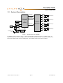
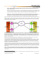
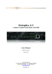
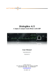
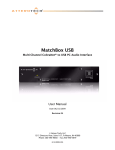
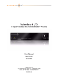
BoomBox NA4 User Manual Date 05/30/13 Revision 02 Attero Tech, LLC 1315 Directors Row, Suite 107, Ft Wayne, IN 46808 Phone 260-496-9668 • Fax 260-496-9879 www.atterotech.com 614-00006-02 BoomBox NA4 User Manual IMPORTANT SAFETY INSTRUCTIONS The symbols below are internationally accepted symbols that warn of potential hazards with electrical products. This symbol, wherever it appears, alerts you to the presence of un-insulated dangerous voltage inside the enclosure -- voltage that may be sufficient to constitute a risk of shock. This symbol, wherever it appears, alerts you to important operating and maintenance instructions in the accompanying literature. Please read the manual. 1. 2. 3. 4. 5. 6. 7. 8. 9. 10. 11. 12. 13. 14. 15. 16. 17. 18. 19. Read these instructions. Keep these instructions. Heed all warnings. Follow all instructions. Do not use this apparatus near water. Clean only with a dry cloth. Do not block any ventilation openings. Install in accordance with the manufacturer's instructions. Do not install near any heat sources such as radiators, heat registers, stoves, or other apparatus (including amplifiers) that produce heat. Do not defeat the safety purpose of the polarized or grounding-type plug. A polarized plug has two blades with one wider than the other. A grounding type plug has two blades and third grounding prong. The wider blade or the third prong is provided for your safety. If the provided plug does not fit into your outlet, consult an electrician for replacement of the obsolete outlet. Protect the power cord from being walked on or pinched particularly at plugs, convenience receptacles, and the point where they exit from the apparatus. Only use attachments/accessories specified by Attero Tech Use only with the cart, stand, tripod, bracket, or table specified by the manufacturer, or sold with the apparatus. When a cart is used, use caution when moving the cart/apparatus combination to avoid injury from tip-over. Unplug this apparatus during lightning storms or when unused for long periods of time. Refer all servicing to qualified service personnel. Servicing is required when the apparatus has been damaged in any way, such as power-supply cord or plug is damaged, liquid has been spilled or objects have fallen into the apparatus, the apparatus has been exposed to rain or moisture, does not operate normally, or has been dropped. This apparatus shall be connected to a mains socket outlet with a protective earthing connection. When permanently connected, on all-pole mains switch with a contact separation of at least 3mm in each pole shall be incorporated in the electrical installation of the building. If rack mounting, provide adequate ventilation. Equipment may be located above or below this apparatus but some equipment (like large power amplifiers) may cause an unacceptable amount of hum of may generate too much heat and degrade the performance of this apparatus, This apparatus may be installed in a industry standard equipment rack. Use screws through all mounting holes to provide the best support. TO REDUCE THE RISK OF FIRE OR ELECTRIC SHOCK, DO NOT EXPOSE THIS APPARATUS TO RAIN OR MOISTURE. Attero Tech LLC 2011-2013 Page i 614-00006-02 BoomBox NA4 User Manual Note: This equipment has been tested and found to comply with the limits for a Class A digital device, pursuant to Part 15 of the FCC Rules and EN55022. These limits are designed to provide reasonable protection against harmful interference when the equipment is operated in a commercial environment. This equipment generates, uses, and can radiate radio frequency energy and, if not installed and used in accordance with the instruction manual, may cause harmful interference to radio communications. Operation of this equipment in a residential area is likely to cause harmful interference, in which case the user will be required to correct the interference at his own expense. Attero Tech LLC 2011-2013 Page ii 614-00006-02 BoomBox NA4 User Manual Contents 1 – Overview.....................................................................................................................................................................................................................1 1.1 – What’s in the Box? .................................................................................................................................................... 1 1.2 – Optional Extras......................................................................................................................................................... 1 1.3 – System Description .................................................................................................................................................. 2 2 – Installation ................................................................................................................................................................................................................3 2.1 – Mechanical................................................................................................................................................................ 3 2.2 – Electrical ................................................................................................................................................................... 4 3 – Configuration...........................................................................................................................................................................................................5 3.1 – Audio Configuration................................................................................................................................................. 5 3.2 – Output Controls ...................................................................................................................................................... 5 3.2.1 – Master Controls................................................................................................................................................ 5 3.2.2 – Channel Controls ............................................................................................................................................. 6 4 – Troubleshooting.....................................................................................................................................................................................................7 4.1 – Checking the Network Connection .......................................................................................................................... 7 4.2 – Common Faults ........................................................................................................................................................ 7 5 – ARCHITECTS & ENGINEERS SPECIFICATION ...........................................................................................................................................8 5.1 – Device Specifications................................................................................................................................................ 8 APPENDIX A – Introduction to CobraNet ....................................................................................................................................................... A-1 APPENDIX B – Reference Documents ...............................................................................................................................................................B-1 Attero Tech LLC 2011-2013 Page iii 614-00006-02 BoomBox NA4 User Manual 1 – Overview The BoomBox NA4 CobraNet Audio Interface is a cost-effective four-channel networked power amplifier for paging and background music applications. Each channel can amplify either of two received CobraNet audio streams. Each channel has its own volume control and signal routing control, and both of these features are configurable and controllable over the network. The BoomBox features the following connectivity: o Audio Output - Four power amplified channels with remotely adjustable volume control o CobraNet Interface Port - Connects the BoomBox to a CobraNet network using standard CAT-5 cable. The BoomBox can be powered by either using PoE from a standard IEEE802.3af compatible PoE network switch, a standard IEEE802.3at compatible PoE+ network switch or injector, or by using an external +12V - +24V DC source. *Note: Maximum output power from a BoomBox requires using either an IEEE802.3at PoE+ switch or a 12V - 24V DC supply. The BoomBox automatically limits its output when using an IEEE802.3af PoE switch to prevent it from exceeding the maximum rating of the PoE connection. Therefore, the output is somewhat reduced. Configuration of the BoomBox is done using the Attero Tech Control Center software. This control software allows realtime manipulation of all signal routing and system configuration. 1.1 – What’s in the Box? The BoomBox comes supplied with the following o BoomBox device 1.2 – Optional Extras All of the following are available as options for the BoomBox: o A 12 V DC power supply is available if PoE or PoE+ power is not required or available. o Single device 1U rack-mount kit. o Dual device 1U rack-mount kit Each optional item required must be ordered separately to the BoomBox. Attero Tech LLC 2011-2013 Page 1 614-00006-02 BoomBox NA4 User Manual 1.3 – System Description Digital Amplifier Control Speaker Output Reset and Fault Interrupts Attero Tech CobraNet LE AT2224 VCXO EEPROM RJ45 CobraNet I/F Regulated +12 to +24VDC Speaker Output 4 Channel Digital Amp Digital Audio Speaker Output XFMR PoE +12V +24V AutoSwitch DC Selector Speaker Output +3.3V +3.3V Switching Regulator Figure 1 – System diagram of a BoomBox The BoomBox system is shown in Figure 1. Power to the BoomBox is supplied via PoE or a regulated supply. The CobraNet LE processor receives the digital audio via the CobraNet Ethernet connector. The LE processor passes the audio to the amplifier which drives the analog output. The amplifier outputs on the NA4 are bridged. Attero Tech LLC 2011-2013 Page 2 614-00006-02 BoomBox NA4 User Manual 2 – Installation Figure 2 – BoomBox Connectors and Indicators 1 Power LED 2 Power Socket – Use with optional 12V to 24 V DC wall wart only. 3 CobraNet Ethernet interface connector and indicators 4 Speaker outputs 2.1 – Mechanical The BoomBox should be securely mounted before connecting the electrical connections. If installation is to be in a rack, use either single or dual rack kits. The rack kit is ordered separately and comes as a separate kit and thus will need attaching to the BoomBox prior to installation into the rack. The rack kits comprise of rack ears and rack extension pieces. The dual rack kit also has an additional center spacer plate. All the screws to attach the rack kits are included though screws to attach the completed rack mountable unit into the rack will be required. To attach a rack kit, attach the rack ears to the fronts of the unit using the supplied pan-head screws. If using the dual rack kit, position the two units, right way up and side by side and use the center spacing plate to connect the two units together using the countersunk screws to form a single mechanical unit. Finally, attach the rack extension pieces to the outside rack ears. Attero Tech LLC 2011-2013 Page 3 614-00006-02 BoomBox NA4 User Manual 2.2 – Electrical Attach the speakers to be used to the appropriate outputs When powering using PoE: o Attach the CobraNet I/F port to a spare PoE-enabled port on a PoE switch using a CAT-5 cable. If a midspan injector is being used, connect a spare input port to the CobraNet network switch using a CAT-5 able, and then connect the corresponding output port to the CobraNet I/F of the BoomBox When powering using an optional external supply: o Attach the CobraNet I/F port to a spare port on the CobraNet network switch using a CAT-5 cable o Attach the power supply to the power input jack and then power up the external supply If all steps are performed correctly, the power light on the front should be lit. There may also be some activity on the BoomBox CobraNet I/F LED indicators. With no CobraNet network, the LED on the right of the CobraNet I/F port will be on. If another active CobraNet device is detected on the network or the Attero Tech Control Center application or other similar CobraNet application program is active on the network, the left hand LED will be flashing at a rate around three times per second and the right hand LED will remain steady. Attero Tech LLC 2011-2013 Page 4 614-00006-02 BoomBox NA4 User Manual 3 – Configuration Configuration of the BoomBox requires the use of the Attero Tech Control Center application. Refer to the Attero Tech Control Center User’s Guide for installation and setup instructions for the application. *Note: Setup of CobraNet parameters on the BoomBox such as bundle setup is done the same as any other device and can be done with software other than Control Center. However, other configuration settings use parameters that are outside the standard set of CobraNet parameters and they require Control Center to set them. 3.1 – Audio Configuration The BoomBox can only make use of two streams at any one time. These audio streams can be selected from any submap of any bundle the BoomBox can receive. Use the Bundle Setup form in Control Center for the BoomBox to setup the required incoming CobraNet audio. Typing “33” into one of the receiver submap fields designates that particular audio stream to be channel 1. Alternately, type “34” to designate a particular audio stream to be channel 2. You do not have to use both if both streams are aren’t required though if you don’t designate a stream for an output and later try and use it, the BoomBox will output nothing. *Note: Both 33 and 34 can only exist once in a particular receiver submap table. If more than one field has 33 or 34 and both bundles are active, the output audio may not be what is expected! Figure 3 shows a receiver setup where both audio streams are being taken received from a single bundle. Figure 3 - Bundle Receiver setup *Note: To ensure the bundle setup is retained during power down, ensure that the BoomBox also has persistence enabled (on the main form). 3.2 – Output Controls Configuration of the BoomBox output parameters can be done by selecting the device in the device list on Control Center and then clicking the Device Setup button. Alternately, you can right click on the desired device and click on the Device Setup option from the menu that pops up. As can be seen from Figure 4, the BoomBox has a set of local output channel controls as well as a master set of controls. The output level of a given output is a combination of the settings for the local channel controls for that channel and the master controls. 3.2.1 – Master Controls Each BoomBox has a master volume control and a master mute control (see the left most controls in Figure 4). The master volume does not override the individual channel volumes but works with them, reducing or increasing, the volume on all channels simultaneously. Figure 4 - BoomBox Configuration Screen The master mute will, when active, mute all output channels. Any changes to any local channel controls or the master volume control will not have any affect on the output level whilst the master mute is active. Attero Tech LLC 2011-2013 Page 5 614-00006-02 BoomBox NA4 User Manual 3.2.2 – Channel Controls Each individual output has its own local set of controls (see Figure 5). At the top is the channel select. This allows selection of which of the two possible audio streams to use for that particular output. Which audio streams are available is determined by the bundle setup. The active channel button will show green, and the inactive channel button show grey. One or the other of the channel select buttons will always be active. To select the other audio stream, simply click the inactive channel select button. There are no restrictions on how many outputs on a given unit can use a particular audio stream or in which order the streams are allocated to the outputs. The channel selection can also be changed on the fly. Figure 5 – Channel Controls Slightly below that is the mute button (marked with an ‘M’). When the button is grey, as shown in Figure 5, the mute is not active. When the button is grey, the mute is active. Clicking the mute button will turn it toggle the mute on or off. The channel mute only affects an individual output. The main control is the volume fader. The fader has a minimum value of 0 and a maximum of 100 Is this still true, or have we audio scaled this?. Moving the fader up increases the volume, moving it down reduces it. Altering the value will change the volume on that channel only. Click and hold the left mouse button down on the slider and drag the mouse forward or backward to move the slider upward or downward respectively. The new volume value is sent to the BoomBox once the mouse button is released. The volume control also accepts a value that is typed in. A single left click on the control will highlight the volume controls text value and typing a new value will overwrite the current text. Once the required value is entered, press the Enter key to complete the process and accept the new value. If a valid number is entered, the control will change to the newly entered number or as close to it as the control’s range allows. The control will revert back to its previous value if an invalid number is entered. If the Enter key is not pressed after entering a new value and a different control is selected, the control that was being edited will revert to its previous value. Attero Tech LLC 2011-2013 Page 6 614-00006-02 BoomBox NA4 User Manual 4 – Troubleshooting 4.1 – Checking the Network Connection The CobraNet network connection can be diagnosed by noting the status of the LEDs just above the Ethernet connector on the BoomBox. These LEDs will be on, off, or flashing depending on the current state of the network connection. Below is a table showing the states of the LEDs and what device status they represent. LED status Device Status Neither LED On No Ethernet Connection Left LED on permanently Right LED off but flashes every 3 seconds Ethernet connected but no devices found Left LED on permanently Connected and CobraNet devices found Right LED flashing 3 times a second Device is a performer Table 1 - CobraNet Interface LED Status 4.2 – Common Faults Below are some common faults. Accompanying each one is a list of the most common solutions. While the lists of solutions are not exhaustive, they represent the majority of the likely failures. The BoomBox does not show up on in Control Center. o If using PoE, check the BoomBox is attached to a PoE-enabled port on a switch or the output port on a midspan injector and the power light on the switch/injector is on o If using the optional wall wart, check power is supplied and the power light is on o Ensure the PC is running Windows 98SE or later (Windows 95 is not suitable) o If running Vista or Windows 7, ensure a Vista compatible version of Control Center is running (1.1.0 onwards) o Check the Ethernet cable is correctly connected o If connected to a switch ensure the link indicator is lit and activity flashes at least occasionally. If not, ensure the correct type of cable is used for the switch. Some switches require standard patch cables. Others can use standard or crossover cables o If connected directly to a PC, ensure the Ethernet cable is a crossover type No audio from an output o If using PoE, check the BoomBox is attached to a PoE-enabled port on a switch or an output port on a mid-span injector and the power light on the switch/injector is on o Check the power light on the unit is lit o Check the LED indicators on the Ethernet port are flashing constantly o Check the unit is receiving a valid bundle o Check the bundle being received has active audio in it o Check the submap settings to ensure active audio is being used o Check the master mute and local channel mute are not active o Check the master volume is at a sufficient level o Check the local channel volume is at a sufficient level Attero Tech LLC 2011-2013 Page 7 614-00006-02 BoomBox NA4 User Manual 5 – ARCHITECTS & ENGINEERS SPECIFICATION The CobraNet interface unit shall provide four channels of speaker level audio amplification. Each channel shall be capable of reproducing either of two CobraNet audio channels that the interface can receive. Each channel shall support volume control. The internal digital to analog signal conversion shall be performed at 16-bit resolution with a sampling frequency of 48 kHz. The CobraNet interface unit shall receive power over the Ethernet cable from an 802.3af or 802.3at PoE compliant network switch, or from a +12 V DC to +24 V DC external power supply (autoswitching). The CobraNet interface shall be compatible with Attero Tech Control Center software monitoring in system applications. The CobraNet interface shall be compliant with the RoHS directive. The CobraNet interface shall be the Attero Tech BoomBox NA4. 5.1 – Device Specifications CobraNet Network Audio Outputs Number of Channels 4 Physical Level: Output Power Based on power source – see below Connector: Single RJ-45 Cable Quality: CAT-5 Transmission Speed: 100 Mbps 802.3af PoE 2W/channel 802.3at PoE or DC 4W/channel THD <.1% @ 1kHz, full power Output Noise <-75dBu Standard Ethernet Class 4, will operate correctly with 802.3af or 802.3at or Power Requirements Optional external PSU 12 V DC @ 2A or 24 V DC @ 1A Attero Tech LLC 2011-2013 Power Consumption < 30 W (PSU dependant) Dimensions 7.5”W x 1.75”H x 5.0”D Weight 27 oz, 760 g Operating Temperature 0 ºC - 40 ºC Compliance RoHS, UL Listed power source, FCC Part 15 Class A Compliant Page 8 614-00006-02 BoomBox NA4 User Manual APPENDIX A – Introduction to CobraNet CobraNet is an audio networking technology for delivery and distribution of real-time, high quality, uncompressed digital audio using a standard Ethernet network. It is implemented using a combination of hardware, firmware, and the CobraNet protocol. Unlike other audio networking or distribution technologies, CobraNet is a true network and exists on standard Ethernet networks using standard Ethernet hardware. Since it is a true network, audio routing is highly flexible between network nodes and can be used in a variety of audio distribution applications. In addition to the high degree of routing flexibility that CobraNet provides, the technology also incorporates the ability to monitor and control CobraNet devices remotely. This is a key feature that is highly important in fixed installation applications where the audio distribution equipment may not be readily accessible. All CobraNet devices on the network can be controlled and monitored from a central location by sending control commands and monitoring device specific parameters. CobraNet provides this capability by implementing Simple Network Management Protocol (SNMP). SNMP is a standard protocol typically used for monitoring network devices such as Ethernet switches. In the case of CobraNet, it allows users to communicate with any CobraNet device using standard SNMP tools or a customized user interface designed specifically for CobraNet, such as Attero Tech’s Control Center application. The figure above represents the types of data that coexist on a CobraNet network. Before a CobraNet system can be configured, it is important to first understand how CobraNet distributes audio between devices. Audio is sent in "bundles" on a CobraNet system. Each bundle is capable of holding up to 8 logical audio channels. Every CobraNet device has a number of bundle transmitters and bundle receivers. These transmitters and receivers are the mechanism used to send and receive bundles between devices. For a transmitted bundle, audio may be sourced either directly from the local audio inputs of the device or from internal audio via the on-board DSP1, but not both simultaneously. Internal audio from the onboard DSP could have originally been sourced from the local device inputs, sent from another CobraNet device or even generated by the DSP itself. Combinations of the local or internal audio may exist within a bundle in any order. Additionally, a single audio source in a device may be used multiple times in a single transmitter bundle or across multiple transmitter bundles. For a received bundle, the received network audio may be routed directly to the device’s local outputs, the internal DSP1 or simply ignored. Once the contents of a bundle have been decided, the next step is to pass the bundle to another CobraNet device. To do this, every CobraNet device has up to 4 bundle transmitters. Each bundle transmitter has a transmit mode that must first be selected. This affects how many devices may receive that particular bundle at a time. The modes are as follows: 1 Not available on all devices – CS496xxx devices only Attero Tech LLC 2011-2013 Page A-1 614-00006-02 BoomBox NA4 User Manual o Unicast – Used for one-to-one connections. In this mode, only one receiver at a time can receive this bundle. Once a link is established from this transmitted bundle to a receiver, any future requests for that bundle from other potential receivers will fail. o Multicast – Used for one-to-many connections. This mode broadcasts its contents over the entire network. There is no restriction on the number of receivers. However, the downside is that CobraNet packets are distributed to all nodes on the network, whether they need them or not thus creating possible network bandwidth issues. o Multi-unicasts – Another one-to-many mode. Whilst this is the most efficient method for getting a bundle to multiple receivers in terms of network bandwidth, it requires more processing power on the CobraNet device so in this mode there is a maximum limit of four receiver connections (this can be reduced if required). If more connections are required than the limit, the node can be configured to automatically switches to multicast. Note: When a bundle must be transmitted to multiple receivers, multi-unicast transmissions should be used where possible. Once the mode is selected, to enable a device to transmit the bundle, simply allocate the particular transmitter bundle a non-zero number. Since this number identifies all the network packets sent out by that transmitter, each transmit bundle number must be unique on a network2. Now that the transmitter is set up, it is time to set up the receivers. In order to receive bundles, each CobraNet device has up to eight bundle receivers. To enable a device to receive a bundle, simply allocate one of that device’s bundle receivers the same bundle number as a transmitted bundle. By doing so, a virtual link is created and audio should now be passed from one device to the other. It should be noted that no knowledge of a device’s network topology or connection is thus required in order to configure audio connections. The only restriction to this is that a device cannot be set up to receive a bundle it is also transmitting. The above case creates a simple, one-to-one, unidirectional link. If more devices are required to receive that bundle, allocate the same transmitted bundle number to a bundle receiver on the other CobraNet devices. It is also important to note that CobraNet supports simultaneous bidirectional audio distribution in each device. Not only could audio be sent from Device A to Device B but at the same time, should it be needed, audio could also be sent from Device B to Device A. The exact bundle and routing configuration will be determined by the needs of each individual installation. An installation may have multiple units transmitting multiple bundles. The only restriction is the bandwidth available on the network to transfer the audio. CobraNet does more than just transfer audio data. It can be used to pass serial information as well. A feature called serial bridging has been incorporated that allows the passage of serial data between nodes. Each node can pass serial data to a specific node or multicast the data to multiple nodes. A node can also receive data from either a single source or multiple sources. Baud rates, data bits, stop bits, parity, and so on are all configurable. There is also support for multi-drop serial buses as well. Finally, CobraNet has the capability to alter all of the above options in real time making the whole system completely dynamic. By use of control software, all of the bundle assignment parameters can be configured with no need to change cables, switch out connectors, or pull new wiring. Most importantly, this control capability can be implemented from a single location! Bundle numbers range from 1 through 65535. A value of 0 represents an inactive bundle. Numbers 1-255 are reserved for multicast mode transmissions only. 2 Attero Tech LLC 2011-2013 Page A-2 614-00006-02 BoomBox NA4 User Manual APPENDIX B – Reference Documents The following table lists the relevant reference documents. Document Title Revision CobraNet Programmer’s Reference (Cirrus Logic) Attero Tech LLC 2011-2013 v2.5 Page B-1 614-00006-02