1
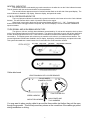
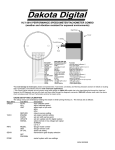
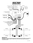
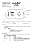
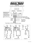
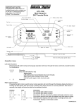
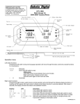
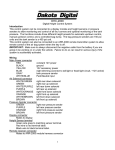
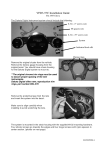
MODEL HLY-5000X
Rev. A
BAR MOUNT
SPEEDOMETER/TACHOMETER
INFORMATION SYSTEM
Please read this before beginning installation or wiring.
POWER
Connect the red wire from the main harness to accessory power from the ignition switch.
A good quality, solid state ignition switch should be used. The contacts on a mechanical “bar” switch can
bounce due to the vibration and cause the system to momentarily loose power and reset itself.
Never connect this to a battery charger alone. It needs to have a 12 volt battery connected to it. Battery
chargers have an unregulated voltage output that will cause the system to not operate properly.
GROUND
The black wire is the main ground for display system. This should be connected directly to the negative
cable on the battery. Connecting to a tank or frame ground can cause a weak or intermittent ground connection. A
poor ground connection can cause improper or erratic operation.
SPEEDOMETER
Failure to calibrate the speedometer may cause your odometer mileage to increase very rapidly.
The speed input connector plugs into the speed sensor to tell how fast you are traveling. On cable driven
applications, the external sensor connects to the speedometer cable and provides the electric signal. The sensor
has a 5/8” course thread fitting that accepts mid-80’s and earlier cables directly. For newer cycles the speedometer
cable will need to be replaced with one having the correct fitting. With two-wire speed sensors the polarity of the
two wires does not matter.
With transmissions having the built-in electric sensor, a three-wire harness adapter connects the
transmission speed sensor to the speedometer. This system will also accept most after-market inductive, Halleffect, or ground switch sensors.
The speedometer is fully adjustable and calibration is listed below.
SPEEDOMETER CALIBRATION
The speedometer calibration is done using the function (trip) switch. The speedometer can be calibrated
two different ways. The first method is to place the unit in auto-cal mode and drive exactly one mile (one km for
metric). The second method is to place the unit in adjust mode and the speed reading can be moved up or down
while driving.
METHOD 1, AUTOCAL
1. Make sure the key is off so the gauge is not powered.
2. Press and hold the function switch.
3. Turn the key on. With the switch still held, start the bike. The display will show “ -- “.
4. Release the function switch. The display will switch between “AUtO” (auto cal), “AdJ” (adjust), “CYL” (cylinder
select), and “SEt” (shift bar).
5. When “AUtO” is displayed press the function switch. This will place the unit in auto calibration mode.
6. Release the function switch. The speedometer will show “–00.0”.
7. Drive exactly one mile (or 1km). The speedometer display will increase as signal pulses are received from the
speed sensor.
8. Press and release the function switch. The calibration value will be calculated and stored. The gauge will now
restart in normal mode with the new speed calibration.
1
1.
2.
3.
4.
5.
6.
7.
8.
9.
METHOD 2, ADJUST SPEED
Make sure the key is off so the gauge is not powered.
Press and hold the function switch.
Turn the key on. With the switch still held, start the bike. The display will show “ -- “.
Release the function switch. The display will switch between “AUtO” (auto cal), “AdJ” (adjust), “CYL” (cylinder
select), and “SEt” (shift bar).
When “AdJ” is displayed press the function switch. This will place the unit in calibration adjustment mode.
Release the function switch. The speed display will flash to indicate that it is in the adjust mode. The
tachometer will operate normally.
Drive at a known speed. Following another vehicle that is driving at a constant, known speed can do this.
Press the function switch. The speed reading will begin increasing until the function switch is released. The
next time the function switch is pressed, the speed reading will begin decreasing until it is released.
Once the speedometer is reading correct release the function switch. The new calibration will be saved if no
adjustments are made for 7-10 seconds.
TACHOMETER
The tachometer is used by connecting the green wire from the main power harness to the negative side of
the coil or to an ignition module tach output. The tachometer is adjustable for 1, 2, 4, 6, or 8 cylinder settings. The
1 cylinder setting is used for single-fire ignition systems without a buffered tach output.
The following instructions are used to set the tachometer calibration:
1. Make sure the key is off so the gauge is not powered.
2. Press and hold the function switch.
3. Turn the key on. The display will show “ -- “.
4. Release the function switch. The display will switch between “AUtO” (auto cal), “AdJ” (adjust), “CYL” (cylinder
select), and “SEt” (shift bar).
5. When “CYL” is displayed press the function switch. This will place the unit in the tach calibration mode.
6. Release the function switch. The display will switch between “1CYL”, “2CYL”, “4CYL”, “6CYL”, and “8CYL”.
7. When the desired setting is displayed press the function switch. The display will show “tACH”.
8. Release the function switch. The system will now start up normally with the new setting.
TACHOMETER RED LINE/SHIFT INDICATOR
A single bar will light up to indicate a shift point or red line. The rpm where the bar lights up is user
selectable and can be turned off completely if desired. The bar is factory set to about 5000 rpm.
The following instructions are used to set the tachometer warning bar:
1. Make sure the key is off so the gauge is not powered.
2. Press and hold the function switch.
3. Turn the key on. The display will show “ -- “.
4. Release the function switch. The display will switch between “AUtO” (auto cal), “AdJ” (adjust), “CYL” (cylinder
select), and “SEt” (shift bar).
5. When “SEt” is displayed press the function switch. This will place the unit in the shift/red line set mode.
6. Release the function switch. The bar display will start at 2 and begin moving up. After it reaches the top it will
go out and then start back at 2.
7. When the desired rpm setting is displayed press the function switch. To disable this feature, press the function
switch while the bar is not displayed. The display will show “tACH” once the new setting is stored.
8. Release the function switch. The system will now start up normally with the new setting.
TRIP ODOMETER
The trip odometer is activated by the push button function switch located on the back, left side of the unit.
Pressing and releasing the button will toggle the display from the trip mileage to the standard speedometer reading
or from the speedometer to the trip odometer. Pressing and holding the button while the trip odometer is displayed
will reset the trip odometer. The trip odometer will read from 0 to 999.9 miles. While the trip mileage is displayed
the unit will occasionally flash “trIP” to indicate it is in trip odometer display mode.
ODOMETER
The trip odometer is activated by the push button function switch located on the back, left side of the unit.
Pressing and holding the button will while the speed is displayed will cause the unit to read out the odometer
mileage. The odometer will read from 0 to 99,999 miles. The speed display will first show “odo”, then the
thousands of miles, then the hundreds of miles.
For example, 34,792 miles would be displayed as “odo”, “ 34”, “ 792”, “ “ and then return to the
speedometer reading.
2
NEUTRAL INDICATOR
The neutral indicator is activated by a ground connection to the white wire on the 5-wire indicator harness.
This will interface with the stock neutral switch on the transmission.
The neutral indicator appears as a pair of vertical bars that flash on the left side of the speed display. The
neutral indicator is disabled in trip display, odometer display, and speed cal modes.
LOW OIL PRESSURE INDICATOR
The low oil pressure indicator is activated by a ground connection to the brown wire on the 5-wire indicator
harness. This will interface with the stock oil pressure switch on the engine.
When there is a ground to the brown wire the speed display will flash “ LO “, “ OIL”. Pressing the push
button function switch will toggle between the speed, trip, and lo oil displays. The low oil indicator is disabled in
speed cal modes.
TURN SIGNAL AND HIGH BEAM INDICATORS
The right turn, left turn, and high beam indicators are activated by 12 volts at their respective hook-up wires
on the 5-wire indicator harness (not the 3-wire harness). The right turn signal wire is green, the left turn signal wire
is black, and the high beam wire is red. These can be connected to the same wires that the indicator lights are
connected to. The display system wire colors may not match the wire colors in your electrical wire harness. The
turn and high beam indicators are disabled in low oil display, trip display, odometer display, and speed cal modes.
This system does not have a speed output wire for automatic turn signal canceling modules.
Cable attachment
VEIW FROM BACK WITH COVER REMOVED
BLACK WIRES
TOWARDS CENTER
FUNCTION SWITCH
SPEED HARNESS
MAIN POWER AND
TACH HARNESS
INDICATOR HARNESS
You may want to place a nylon cable tie around the three cables just before they exit the case
though the grommet. This will help avoid any stress on the connectors if the cables get pulled
during installation or driving.
3
MOUNTING
A mounting bracket must be purchased for your application. Some of the current brackets are: BKT-5001
1” bar mount, BKT-5002 flat triple-tree mount, BKT-5003 35° triple-tree mount, BKT-5004 1-1/4” bar mount, BKT5005 1-1/2” bar mount, and BKT-5006 1” riser bar mount. The bar mount brackets can be used for above-the-bar
mounting or below-the-bar mounting. The 35° triple-tree mounts are only available for above-the-bar mounting.
The triple-tree mounting bracket replaces the original handle bar mount. The gauge attaches to the back
side of the bracket with the supplied screws.
The bar mount brackets have a curved front bracket and two rear brackets. The longer screws attach the
gauge to the back side of the bracket and the shorter screws go into the recessed openings on the rear brackets.
The mount fits tight and will need to be pulled together by the screws.
To mount the gauge under the bar:
1. Remove the rear plate by unscrewing the four screws.
2. Remove the rubber cap from the switch.
3. Flip the rear plate over so the mounting tab is on the top. The hole for the switch should stay on the
same side.
4. Place the switch through the hole and replace the rubber cap.
5. Reattach the rear plate using the four screws.
6. Place bar mount bracket on the handle bars so that the recessed screw holes are on the top.
7. Using the long screws, secure the gauge to the bottom side of the bar mount bracket.
Drawings for using bar mount brackets above the bar and below the bar.
back plate for
under-bar mounting.
WIRING
In order to ensure that there are no problems with voltage drops causing the system to shut down, a heavy
duty, solid state ignition switch is recommended. Also, the black wire should be connected directly to the negative
battery terminal to avoid erratic operation due to a poor ground connection. The stock harness color is listed for
reference only. Actual colors may vary with different models and years.
HLY-5000X 3-wire
Stock harness color Function
RED
ORANGE/WHITE
+12 volt with key on
BLACK
BLACK
ground (connect directly to battery)
GREEN
PINK
tachometer signal
HLY-5000X 5-wire
Stock harness color Function
RED
WHITE
High Beam indicator
BLACK
VIOLET
Left Turn indicator
GREEN
BROWN
Right Turn indicator
WHITE
TAN
Neutral indicator
BROWN
GREEN/YELLOW
Low Oil Pressure indicator
4
Speedometer connection varies depending on the year and model of the cycle. Using different speed adapter kits
the speedometer can read a speedometer cable, a stock electric transmission speed sensor, or an aftermarket
gear-tooth sensor. Each adapter kit connects to the speedometer using the three pin connector on the back of the
system, underneath the back plate.
SEN-5011:
The cable adapter accepts a 5/8” thread fitting and can be mounted in a concealed location.
Cycles that have a metric-threaded speedometer cable will need to have the cable modified or replaced.
SEN-5012:
The adapter harness for using a stock transmission speed sensor converts the triangular connector
to the in-line connector on the speed/tach system.
SEN-5017:
The transmission speed sensor mounts into the stock sensor port on most 96 and up OEM and
aftermarket big twin transmissions. The sensor reads the final drive gear inside the transmission. With aftermarket
transmissions or aftermarket gear sets be sure to check the sensor to gear spacing.
SEN-5018:
The rear wheel sensor kit consists of a sensor mounted to the rear wheel spacer and a harness to
connect it to the digital speedometer. The sensor reads the hub bolts. It will work with most softail® and rigid
applications.
SEN-5019:
The gear-tooth sensor kit consists of a two-terminal sensor and a harness to connect it to the
speed/tach system. The sensor needs to be mounted within 1/8” of the teeth on a steel final drive gear.
WARRANTY
All DAKOTA DIGITAL instruments are warranted free of defects in material and workmanship for 2
years from the date of purchase. In the event of a problem with one of our products within the warranty period, DAKOTA
DIGITAL will replace or repair the instrument at no charge. (The decision to repair or replace is solely that of DAKOTA
DIGITAL. DAKOTA DIGITAL is not responsible for shipping costs of products returned under warranty or for labor charges for
product installation and removal.) This warranty becomes invalid if the product is misused, altered or installed incorrectly.
For warranty coverage, you must first call to receive an RMA#. Ship the product transportation prepaid via UPS or
insured Parcel Post. A copy of the original invoice or dated bill of sale along with a description of the defect is also required.
Make sure that the RMA number is clearly visible on the outside of the package as well as inside on the paper work.
The above warranties, both expressed and implied, do not cover damages caused by improper installation, misuse,
abuse, fire, unauthorized modifications, floods or acts of God, or reimbursement of customer or shop time. The extent of the
warranty is limited only to the product and does not cover any loss or damage to vehicle, equipment, or non-DAKOTA DIGITAL
products.
SERVICE AND REPAIR
DAKOTA DIGITAL offers complete service and repair of its product line. In addition, technical consultation is available
to help you work through any questions or problems you may be having installing one of our units.
Should you ever need to send the unit back for repairs, please package the product in a good quality box along with
plenty of packing material. Ship the product by UPS or insured Parcel Post. Be sure to include your RMA#, a complete
description of the problem, your full name and address (street address preferred), and a telephone number where you can be
reached during the day. A return authorization number (RMA#) for products being return for repair is required. Do not
send any money. We will bill you for the repair charges.
Troubleshooting guide.
Problem
Gauge will not light up
Possible cause
Red wire does not have
power.
Black wire is not getting
a good ground.
Gauge is damaged.
Solution
Connect to a location that has power.
Return gauge for repair. (see instructions)
Gauge lights up, but displays
“SPd” “Err”
Speed calibration is invalid
Gauge must be recalibrated (see instructions).
Gauge lights up, but displays
“tCH” “Err”
Tach calibration is invalid
Reset cylinder selection (see instructions).
Gauge lights up, but displays
just “Err” only
Gauge is damaged.
Return gauge for repair. (see instructions)
Gauge lights up, but speed
will only show zero.
Speed harness is not connected Check 3 pin connector on the back of the
properly to speedometer.
speedometer.
Speed harness is not connected Check connection from speed harness
properly to sensor.
to the speed sensor.
Speed sensor not grounded
Move ground to different location,
properly.
preferably close to speedometer ground.
Speed sensor is not being
Check cable connection at both ends
turned by the cable.
Sensor can be tested by spinning the
cable with a drill.
Connect ground to a different location.
5
Gauge lights up, but speed
will only show zero, cont.
Speed harness is not connected Check 3 pin connector on the back of the
Sensor is not sending a speed See speed sensor voltage checks listed
signal.
below.
Gauge is not calibrated
Gauge must be recalibrated (see instructions).
Speed reading is erratic or
jumps around.
Speed sensor wire is loose
or broken.
Cable is loose or broken.
Poor ground connection.
Check all wire connections and inspect wire
for breaks.
Check cable between sensor and
transmission.
Check ground connection on speedometer
and sensor.
Speed reading is incorrect.
Gauge is not calibrated
correctly.
Gauge must be calibrated (see instructions).
Speedometer reads “255”
while driving.
Gauge is not calibrated
correctly.
Gauge must be calibrated using “auto cal”
(see instructions).
Gauge lights up, but tach
will only show zero.
Tach wire is not connected
properly.
Ignition system not grounded
properly.
Gauge is not grounded
properly.
Gauge is not calibrated
Check connection from green tach wire to
tach signal wire.
Check engine and ignition system grounds.
Tach reading is erratic or
jumps around.
Tach signal wire is loose
or broken.
Poor ground connection.
Tach reading is incorrect.
Gauge is not calibrated
correctly.
Check gauge and engine grounds.
Gauge must be recalibrated (see instructions).
Check all wire connections and inspect wire
for breaks.
Check ground connection on tachometer
and engine.
Gauge must be calibrated (see instructions).
Speed sensor voltage checks. All checks should be made with the sensor connected to the gauge and the
key on. Checks should be done with a volt meter and not a test light.
3-wire sensor: Red wire should have 9-11 volts dc, slightly less than battery voltage.
Black wire should show ground, 0 volts dc at all times.
Green wire should vary between 0 and 5 volts dc as the gear teeth pass by the sensor.
2-wire sensor: Measure the voltage between the two sensor wires. With the wheel spinning the voltage should be
about 1-10 volts ac (make sure the meter is set to AC volts and not DC volts for this check).
4510 W. 61ST St. N., Sioux Falls, SD 57107
Phone: (605) 332-6513 FAX: (605) 339-4106
www.dakotadigital.com
[email protected]
©Copyright 2003 Dakota Digital Inc.
6