1
F4-BMS 2.0 Technical Manual
FALCON 4.0
BMS v 2.0
Manual
All trademarks and registered trademarks are the property of their respective owners.
1
Table of contents
FEATURE OVERVIEW.................................................................................................................... 7
2
3
4
1.1
Graphics Engine............................................................................................................ 7
1.2
Performance Enhancements ....................................................................................... 7
1.3
Artificial Intelligence...................................................................................................... 7
1.4
Avionics.......................................................................................................................... 7
1.5
Sound Engine ................................................................................................................ 8
1.6
2D / 3D Cockpit .............................................................................................................. 8
1.7
Interactive Training ....................................................................................................... 8
1.8
Input Devices ................................................................................................................. 8
1.9
Cockpit Building ............................................................................................................ 8
INSTALLATION ....................................................................................................................... 9
2.1
General Installation ....................................................................................................... 9
2.2
The F4-BMS Config Editor.......................................................................................... 10
2.3
Theater Installation...................................................................................................... 13
CONFIGURATION................................................................................................................. 15
3.1
Graphics Setup ............................................................................................................ 15
3.2
Advanced Graphics Setup ......................................................................................... 16
3.3
Simulation Setup ......................................................................................................... 17
3.4
Sound Setup ................................................................................................................ 19
WEATHER ............................................................................................................................. 21
4.1
Introduction.................................................................................................................. 21
4.2
Dynamic Weather ........................................................................................................ 21
4.3
Turbulence ................................................................................................................... 22
5
ARTIFICIAL INTELLIGENCE ................................................................................................ 23
6
AVIONICS .............................................................................................................................. 24
2
6.1
Doppler Beam Sharpening (DBS).............................................................................. 24
6.2
Track While Scan(TWS) / “Twiz“ ............................................................................... 24
F4-BMS 2.0 Technical Manual
7
8
6.3
Non F-16 HUD Symbology ......................................................................................... 25
6.4
Voice Messaging System (VMS) / Bitching Betty.................................................... 26
6.5
UHF Radio Fix.............................................................................................................. 26
6.6
Antenna Elevation ....................................................................................................... 26
6.7
Mavericks ..................................................................................................................... 27
6.8
Other Fixes / Enhancements...................................................................................... 27
6.9
Micro-managing the Stores Management System.................................................. 32
6.10
HUD / Avionics............................................................................................................. 34
AIRCRAFT ............................................................................................................................. 35
7.1
Dynamic Roll Inertia.................................................................................................... 35
7.2
Two Engines ................................................................................................................ 35
7.3
F-16................................................................................................................................ 35
7.4
F/A-18............................................................................................................................ 36
7.5
F-14................................................................................................................................ 37
7.6
F-15................................................................................................................................ 38
7.7
F-4.................................................................................................................................. 39
AUTOPILOT........................................................................................................................... 40
8.1
9
Changes from SP3 ...................................................................................................... 40
BMS AP Operation Summary................................................................................................ 42
9.1
10
Guidelines for AP Use................................................................................................. 43
INPUT DEVICES ............................................................................................................... 44
10.1
Native TrackIR Support............................................................................................... 44
10.2
Changes to the handling of input devices ............................................................... 45
11
2D / 3D COCKPIT.............................................................................................................. 56
11.1
3D Clickable Cockpit................................................................................................... 56
11.2
Cockpit Auto Scaling .................................................................................................. 56
11.3
Mouse Scroll Wheel and Middle Mouse Button....................................................... 56
11.4
Adjustable FOV............................................................................................................ 57
11.5
Other Additions To The 2D Cockpit .......................................................................... 57
3
11.6
12
ADDITIONAL FIXES / FEATURES................................................................................... 59
12.1
Miscellaneous .............................................................................................................. 59
12.2
New Keystrokes........................................................................................................... 62
12.3
Winamp Support.......................................................................................................... 62
12.4
Displacement Cam ...................................................................................................... 63
12.5
Air Traffic Control - New Traffic Calls ....................................................................... 63
12.6
TACAN Radio Horizon ................................................................................................ 64
12.7
Updated Nose Wheel Steering................................................................................... 64
13
14
4
Other ADditions To The 3D Cockpit.......................................................................... 58
MULTIPLAYER ENHANCEMENTS.................................................................................. 65
13.1
TCP/IP Maximum Transmission Unit size (MTU)..................................................... 65
13.2
Disable packets loss ................................................................................................... 65
13.3
Bandwidth Switch ....................................................................................................... 66
13.4
standardize UI comms and bandwidth setting ........................................................ 66
REFUELING ......................................................................................................................67
F4-BMS 2.0 Technical Manual
Appendices
Appendix A: COUNTERMEASURES PLACEMENT .................................................................... 68
Appendix B: NEW KEYBOARD COMMANDS AND COUGAR PROFILE................................... 69
Appendix C: AIRCRAFT CONFIG NOTES.................................................................................... 70
Appendix D: 2D COCKPIT ADDED FEATURES .......................................................................... 73
Appendix E: COCKPIT ADDED SWITCHES AND DOF’S ........................................................... 78
Appendix F: BMS COCKPIT BUILDER’S GUIDE ......................................................................... 83
Appendix G: DDS AND COMPRESSED TEXTURES NOTES .................................................. 146
Appendix H: FLIGHT MODEL NOTES ........................................................................................ 147
Appendix I: INTERACTIVE TRAINING........................................................................................ 151
Appendix J: PARTICLE EXPLOSION EFFECTS........................................................................ 158
Appendix K: REFUELING NOTES .............................................................................................. 163
Appendix L: SOUND TABLE NOTES.......................................................................................... 166
BENCHMARKSIMS CREDITS .................................................................................................... 168
5
6
F4-BMS 2.0 Technical Manual
FEATURE OVERVIEW
1.1
GRAPHICS ENGINE
New features include: D3D-compliant hardware and software TNL (transform and lighting), ZBuffering, DXTn compressed texture support, light scattering, terrain vertex lighting, volumetric
vertex fog, highly detailed 3D cumulus, cirrus, stratus, and overcast clouds, cloud shadows,
heavy cloud transitions, lightning, rain, and an all-new particle system for high quality FX.
NOTE:
Due to fundamental changes in the weather engine, bad weather is undergoing a complete
rewrite and is not yet fully implemented, and has therefore been disabled from the UI.
1.2
PERFORMANCE ENHANCEMENTS
Optimized graphics and sim performance is one of the highlights of F4-BMS 2.0. The infamous
“Falcon stutters“, especially in feature-rich areas, and over the FLOT, are a thing of the past.
Coupled with the offloading of graphical chores from the CPU to the GPU (video card), and SSE
optimizations throughout the executable, Falcon 4 is no longer the performance dog it once was.
NOTE:
One remaining campaign pause (rare 1-2 second stutter) has eluded us so far and is currently
under investigation.
1.3
ARTIFICIAL INTELLIGENCE
Various additions and bug fixes have been introduced, such as more realistic helicopter
operations, improved BVR logic, individual aircraft attack speeds, and the ability to customize AirTo-Ground attack altitudes.
1.4
AVIONICS
Avionics upgrades and bug fixes constitute a significant portion of this update. Much time and
effort has gone into refining many areas in the avionics department. This includes a massive
Auto-Pilot overhaul, HUD enhancements and weapons employment.
7
1.5
SOUND ENGINE
The Falcon 4 sound engine now features doppler and distance effects, improved engine effects,
and general positional sound improvements. Users may now customize their sounds more than
ever via the f4sndtable.txt file, and control the properties of all sounds in any way they so choose.
1.6
2D / 3D COCKPIT
Automatic 2D cockpit resizing, a clickable 3D pit, and a host of other enhancements.
1.7
INTERACTIVE TRAINING
Interactive training missions can now be written, which can teach the user hands on how do fly
the aircraft.
1.8
INPUT DEVICES
Falcon 4 now has fully native TrackIR support and a new mouselook mode. The controller polling
routines have been substantially rewritten, now allowing the simultaneous use of up to 16 devices
for up to 23 in-game axis.
1.9
COCKPIT BUILDING
Much work has gone into adding support for those who build their own physical cockpits. Endless
callbacks and exports have been made, as well as a key file with every function and every state
available in Falcon 4. This should make the cockpit builder’s life much easier.
8
F4-BMS 2.0 Technical Manual
2
INSTALLATION
2.1
GENERAL INSTALLATION
The instructions provided below do not cover the installation of patches from the F4UT or
FreeFalcon groups. BMS 2.0 requires Falcon SP3, SP4, or FreeFalcon 2 or FreeFalcon 3.
2.1.1.1
Back up your log book (callsign.lbk) (and any other files you may wish to retain, but
NOT callsign.pop, or display.dsp!).
2.1.1.2
Install a fresh copy of Falcon 4 from your CD, followed by the 1.08US patch, then
either SP3/SP4, or SP3+FreeFalcon2. Install any additional cockpit, skins, terrain
tiles, or models before installing F4-BMS.
DO NOT INSTALL ANY NEW THEATERS AT THIS POINT IN TIME.
2.1.1.3
Run the F4-BMS 2.0 installer and install the patch. Following file extraction, two tools
will automatically run: LxFixer and TexCompress. Do not interrupt them, they will
automatically close upon completion and are vital to a successful install. Finally, the
installer will launch the F4-BMS Config Editor program.
NOTE:
With the exception of 2D cockpit textures, F4-BMS no longer supports paletted textures
(BMP object textures or PCX terrain tiles) in-sim. However, compatibility with all existing
skin addons and terrain tiles is guaranteed with the new TexCompress and
SeasonSwitcher tools.
The TexCompress and SeasonSwitcher tools replace the in-game texture compression
features found in F4-BMS 1.03. TexCompress extracts and converts Falcon’s paletted BMP
textures to compressed DXTn DDS textures, and need only be used with first-time installs, or
after adding BMP textures via F4Patch or LOD Editor. SeasonSwitcher offers the ability to
extract terrain tiles, applying one of 4 seasons. To switch to a different season, or after installing
new tiles, you must re-run SeasonSwitcher to compress the paletted PCX terrain tiles
(texture.zip).
9
2.1.1.4
In the Editor, tick the "(SP) Falcon Configuration" check-box and hit "Apply". Now is a
good time to go through the sub-patches and apply the options you want as there are
many that are not applied by default. After checking the boxes you want, hit “Apply“
again, and close the program.
2.1.1.5
Double-click on the F4-BMS shortcut, located on your desktop, to launch F4-BMS.
Once in-sim, create a new pilot, then configure your Graphics, Sound, Sim, and Input
settings. Be sure to click both "Advanced" buttons in both the Graphics tab and the
Controllers tab.
NOTE:
When making changes to any of the advanced Graphics options, or when changing video card
and/or driver, you must restart Falcon for the changes to take effect.
2.1.1.6
Quit F4-BMS, then copy your previously saved log book (callsign.lbk) over to the
[FalconRoot]\config\ directory.
NOTE:
TE´s and campaigns created or saved with BMS 2.0 are NOT compatible with any previous
versions of Falcon 4. Furthermore, TE’s and campaigns created or saved with any prior version
of BMS are NOT compatible with BMS 2.0.
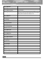
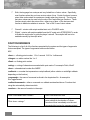
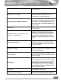
2.2
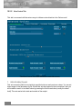
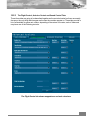
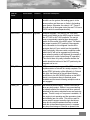
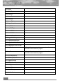
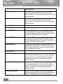
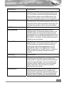
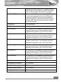
THE F4-BMS CONFIG EDITOR
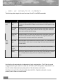
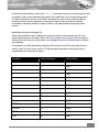
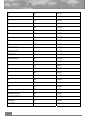
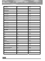
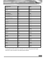
At this point in time, you may wish to further tailor the configuration options located in the BMS
Config Editor. The following table offers descriptions and recommended settings for each
configuration option in the “Settings Benchmark Sims” tree.
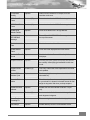
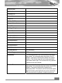
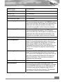
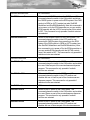
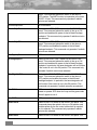
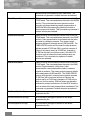
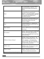
Table 3.2
Patch
Recommendation
Remarks
3D Clickable
Cockpit
Optional
Enables the 3d Clickable Cockpit.
Aeyes DED Font
Spacing Fix
Optional
Fixes issues with Aeyes 1600x1200 DED font
spacing.
Any Waypoint
Tasking
Optional
Select any tasking order for any waypoint, regardless
of mission. For advanced users only.
Auto Scale Fonts
Optional
Automatically scales cockpit fonts one step at 1600.
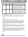
10
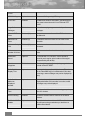
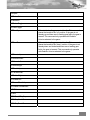
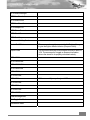
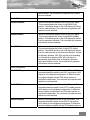
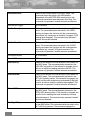
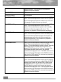
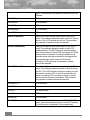
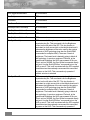
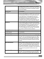
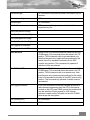
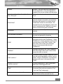
F4-BMS 2.0 Technical Manual
Cockpit Auto
Scaling
Optional
Scales various resolutions of cockpits, from one
resolution to the next.
DSB1 Scan Rate
Factor
Enabled (.75)
Determines how fast the DSB1 Radar image is drawn.
DSB2 Scan Rate
Factor
Enabled (.85)
Determines how fast the DSB2 Radar image is drawn.
Disable High
Altitude Fartiles
Optional
Never let the fartiles kick in at high altitudes.
Disable ACMI
RECORDING
Message
Optional
Turns off the ACMI RECORDING message shown at
the top of the screen.
Disable Lens
Flare
Optional
Disables the sun lens flare effect.
Disable Missile
Flame
Optional
Turns off the star displayed with missile flames.
Disable UI Takeoff
Sound
Optional
Disables the UI takeoff sound effect. Helpful for
Multiplayer.
DisplacementCam
Optional
Activating this option makes the camera 'float' around
the currently viewed (flying) aircraft while in orbit view
mode.
Doppler Sound
Update
Enabled (10)
How many milliseconds must elapse before the sound
code updates.
Enable FCC
SubNav Cycle
Optional
Enables cycling Nav steerpoint modes with the FCC
submodes key.
Dynamic Roll
Inertia
Optional
The roll inertia will now increase when you add stores
to your aircraft. It is dynamic in that will account for fuel
weight in wing tanks and when you drop weapons.
Enable Hud AOA
Indicator
Optional
Enables the HUD AoA indicator for NON F-16 jets
only.
FOV Increment
Enabled (05)
Set how much the field of view should change for
each keypress in degrees.
Force Feedback
Centering Fix
Enabled
Fixes centering for some force feedback joysticks.
GR Bullseye
Optional
Enables Bullseye cursor in Ground Radar modes.
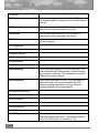
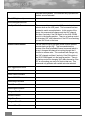
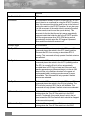
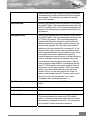
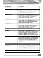
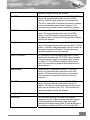
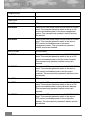
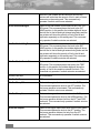
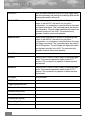
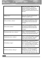
11
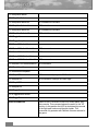
Cursor
HTML Briefings
Optional
Generates Briefings using HTML tags.
HUD Fixes
Enabled
Enables bent negative pitch ladder, extended horizon
line, ghost horizon line and X'd out FPM and STPT
boxes.
Large Strike
Packages
Enabled
Allows for campaign to generate > 4 ship strike
packages.
Maverick EXP
Zoom
Enabled (2.0)
Controls the amount of zoom of the EXP modes on
the Maverick.
Maverick FOV
Zoom
Enabled (4)
Controls the amount of zoom of FOV mode on the
Maverick
Maximum Cockpit
FOV
Enabled (80)
Limits the maximum amount that the FOV can be
increased.
Maximum
Number of Voices
Optional
Maximum number of voices allocated by the sound
code.
MultiEngine
Sound
Optional
For aircraft with 3 or 4 engines, Falcon will play a
sound for each engine, at the location of the engine
(as specified by the dat file).
Precision
Waypoints
Enabled
Fixes the “grid snap bug” when placing waypoints in
2d and via the ICP DEST.
Radio Subtitles
Display Time
Optional
Governs the time a radio subtitle is drawn. This value
(in the FalconBMS.cfg) is in milliseconds. If this value
is too large, newer messages may not be displayed (in
time).
Radio Subtitles
Maximum
Displayed
Number
Optional
Determines the maximum number of simultanously
displayed subtitles. If this number is too short, newer
messages may not be displayed.
Realistic Mav
Time
Enabled
Enables realistic Maverick seeker head gyro spool up
time of 3 minutes.
Recon Lat/Long
Enabled
Shows the selected object’s Lat/Long in the Recon
Window.
Roll-Linked NWS
Rudder
Optional
Controls whether the rudder and NWS are linked to
the roll input on the ground when you don't have a
rudder control device.
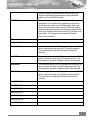
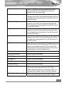
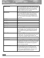
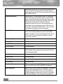
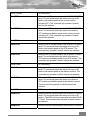
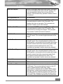
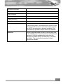
12
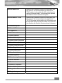
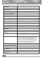
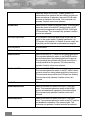
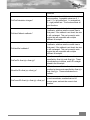
F4-BMS 2.0 Technical Manual
Scramble
Missions
Enabled
Enables scramble missions.
Smaller Bullseye
Optional
Scales the bullseye icon to a more realistic size. May
be too small for lower resolutions.
Smaller HSD
Symbols
Optional
Scales the waypoint symbols on the HSD display
down to more realistic sizes. May be too small for
lower resolutions.
Tex Detail Factor
Optional
Use higher resolution textures at higher altitudes.
TrackIR Pitch
Percentage
Optional
Configures the up/down zones for TrackIR 2D mode.
TrackIR Sample
Frequency
Optional
Configures the rate of view changes while in the 2D
cockpit
TrackIR Yaw
Percentage
Optional
Configures the left/right zones for TrackIR 2D mode.
Winamp
Optional
Activating this option enables WinAmp 2.xx control
from inside falcon.
WinAmp Volume
Optional
Configures the inital WinAmp volume on starting up
Falcon.
2.3
THEATER INSTALLATION
NOTE: All theaters released prior to F4-BMS 2.0 are not officially supported, you are on your
own! That said, here is some advice to get you started:
¿
Install F4-BMS 2.0 per above instructions.
¿
Install the theater.
¿
It is important to note here that a proper theater installation program should copy the
necessary files it needs into its own theater directory. Also, the <theater>.tdf and
<theater>.tga files are copied into the [FalconRoot]\terrdata\theaterdefinition\ folder. The
main benefit of this is that multiple theaters can be installed, without affecting your current
BMS installation.
¿
Copy and paste the [FalconRoot]\terrdata\weather\ folder into the theater’s terrdata folder.
If you do not perform this step, the theater will CTD.
¿
After switching to the new theater in-game, you will need to compress textures via the
[FalconRoot]\TexCompress.exe and SeasonSwitcher.exe tools.
13
NOTE: Some theaters have their own objects, art, and art1024 and sounds folders. Almost all
theaters copy from existing Falcon 4 folders, then modify those, One possible exception to this is
the ODS 512 theater.
14
F4-BMS 2.0 Technical Manual
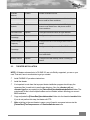
3
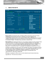
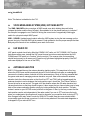
3.1
CONFIGURATION
GRAPHICS SETUP
New options include the “3D Clouds“, “Cloud Shadows”, and “Terrain Lighting“ check boxes. The
“3D Clouds“ option toggles the display of cumulus clouds, which could be a performance killer on
older video cards. The “Cloud Shadows” option toggles cumulus shadows, while the “Terrain
Lighting” option toggles terrain vertex lighting. These last two options may affect performance on
slower processors. Finally, some old, obsolete options were removed as they are no longer used
by the graphics engine.
15
3.2
ADVANCED GRAPHICS SETUP
Anisotropic Filtering: This enables Anisotropic texture filtering. Falcon 4 does NOT support
forcing anisotropic filtering through video card drivers. Doing this will cause visual anomalies,
such as blue outlines around cockpit parts. Therefore, your video card anisotropic settings MUST
be set to “Application Preference.“
Mipmapping: This option enables mipmapping of object textures. Enabling this will reduce
texture shimmering and swimming, at the price of consuming more video memory.
Linear Mipmap Filtering: When used in conjunction with mipmapping, this option enables trilinear filtering. However, some older video cards may suffer from a performance hit.
Render GM To Texture: With this option enabled, the GM radar will be rendered to a texture,
providing a significant performance gain on most video cards.
Rendered 2D Cockpit: Enabling this will force the 2D cockpit to be rendered as polygons,
instead of being “blitted“ to the back-buffer, resulting in substantial performance gains.
Texel Bias Fix: Enabling this option fixes text corruption and 2D cockpit “cracking“ on most
modern video cards. Older video cards may need this disabled.
Textured TV/IR: Enabling this option will force all TV/IR displays to display fully textured objects
and terrain.
16
F4-BMS 2.0 Technical Manual
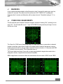
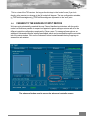
3.3
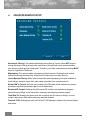
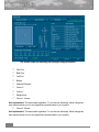
SIMULATION SETUP
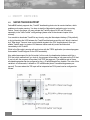
Display Infobar: Activating this option will display additional information about the currently
viewed object at the bottom of the screen. This feature can also be toggled by the
"ToggleInfoBar" keypress (which is not mapped by default) while in 3D. Neither color nor type of
information displayed can be customized. GS refers to 'Ground Speed' while IAS is an acronym
for 'Indicated Air Speed'. This feature only works while in external views.
Radio Subtitles: By activating this feature it is now possible to display the radio messages heard
in the falcon universe. This feature is exclusively activated/deactivated in the configuration
screen, however it can be momentarily toggled by mapping and pressing the "ToggleSubTitles"
key. This key is not mapped by default. In the standard configuration, a message will be
displayed for 10 seconds, and up to 10 messages will be displayed at the same time. As more
messages are displayed, the more recent ones are added at the bottom of the display and move
their way up as the older messages get removed. You can configure both the 'time to live' (TTL)
and the maximum number of displayed messages by editing the "g_nSubTitleTTL" and
"g_nNumberOfSubTitles" options in the falconbms.cfg file. The time values for the
""g_nSubTitleTTL" option are in milliseconds.
Messages are displayed in different colours, which indicate the radio channel where they
originated from. The colours are as follows:
17
green for the "To/From flight" channels
red for the "To package" channels
yellow for the "To/From package" channels
blue for the guard (or 'team') channel
cyan for the proximity channel
dark grey for the 'broadcast' channel
black for the "To/From tower" channel
white for some other (unspecified) messages
It is possible by changing the colours by using these falconbms.cfg lines
¿
g_sRadioflightCol
¿
g_sRadiotoPackageCol
¿
g_sRadioToFromPackageCol
¿
g_sRadioTeamCol
¿
g_sRadioProximityCol
¿
g_sRadioWorldCol
¿
g_sRadioTowerCol
¿
g_sRadioStandardCol
The color has to be entered as string and in hex format, where the first byte indicates the alpha,
the second byte the blue colour component, the third byte the green colour component and the
last byte the red colour component. So if you wanted to set the 'flight' channel to blue you would
enter 'set g_sRadioflightCol "0xFFFF0000"', if you wanted the team channel set to read, you
would enter 'set g_sRadioTeamCol "0xFF0000FF"'.
Please note also that in the falcon universe way more messages are created than are actually
played (as falcon plays radio messages in succession), so you may not hear all displayed
messages. Please also note that sometimes audible messages 'lag' behind the displayed ones,
this is again caused by the way radio messages are played.
The radio frags are located in the 'F4Talk95v1-0-0.csv' file located in your Falcon4 main directory.
This came from Codec´s 'Talkview' program (which still can be gotten from the checksix file
archive) so big cheers are in order for Codec and the F4 voice group who typed them up.
Thanks !
You can change this file, but please take care to keep the current formatting, be especially careful
not to add any newlines ! (or rather, any new frags at all). Should you mess something up, Falcon
may not be able to read the .csv file any more, which would result in a deactivated subtitle option.
18
F4-BMS 2.0 Technical Manual
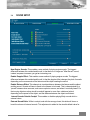
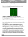
3.4
SOUND SETUP
New Engine Sounds: This enables a new method of playing engine sounds. The biggest
difference between this method and the old, is that there is no longer an "After Burner" sound;
instead, as power increases, you get an increasing roar.
Enable Doppler Effect: This enables a new method of playing engine sounds. The biggest
difference between this method and the old, is that the doppler effect changes the pitch of sounds
depending on the movements of the listener and the object creating the sound.
Enable Distance Effect: This attempts to simulate distance between the listener and the object
emitting sound. Sounds will have to travel to the listener to be heard. This is characterized by a
“pause” between when an event, such as an explosion occurs, and when it is actually heard. For
fast moving objects such as aircraft, sound will appear to come from a distance behind,
depending on the speed of the object, and the distance between the object and listener.
Internal Sounds Outside Cockpit: This enables or disables playing Betty sounds while in
external views.
External Sound Slider: While in-cockpit, and with the canopy closed, this slider will lower or
boost the volume of external sounds. This adjustment is added to the aircrafts default value for
19
lowering external sounds Slider ranges: Full Left: Practically silences all external sounds; Center:
No extra effect; Full Right: Boosts (when possible) external sounds.
Refer to the Appendices for Sound Table information.
20
F4-BMS 2.0 Technical Manual
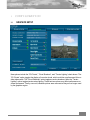
4
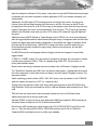
4.1
WEATHER
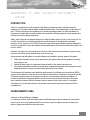
INTRODUCTION
BMS 2.0 features a physically-based weather engine, including real-time light scattering, terrain
vertex lighting, volumetric vertex fog, highly detailed 3D cumulus, cirrus, stratus, overcast clouds,
cloud shadows, heavy cloud transitions, lightning, and rain.
4.2
DYNAMIC WEATHER
The weather in Falcon 4 is now dynamic. When starting a new campaign, or entering a TE, IA, or
DF scenario, a random weather condition will be generated, along with all relevant atmospheric
conditions. The weather will gradually change over time, a maximum of once per day. After
saving a campaign, the current weather at that point in time will also be saved. The current
weather at any point in time may be overriden by selecting one of 4 pre-set conditions in the
Graphics Setup tab.
21
NOTE:
The MP (Multiplayer) weather implementation has undergone extensive changes. Unfortunately,
this means that BMS is no longer compatible with the SP3 executable. Furthermore, TE´s and
campaigns created or saved with BMS 2.0 are NOT compatible with any previous version of
Falcon 4.
4.3
TURBULENCE
The virtual universe just became more dynamic. BMS 2.0 introduces a sophisticated turbulence
model that takes into account a wide variety of conditions. A player will experience different
turbulence intensities and durations depending on weather conditions, time of day, altitude,
vicinity to clouds, and terrain. Also modeled is tropopause boundary turbulence (35k-36k
altitude).
22
F4-BMS 2.0 Technical Manual
5
ARTIFICIAL INTELLIGENCE
¿
If placed at an airbase, helos will spawn on the ground and wait until their takeoff time before
taking off. Helo formation and altitude flying have been adjusted as well. When the mission is
over, helos will return to the base and land (no more #1 landing while the rest stay stuck at
500 feet).
¿
Helicopter AI will now fire Hellfires at the correct stand-off distance.
¿
BARCAP station area increased to 50NM. Please note that you must request and receive
permission from AWACS to leave your station area for the mission to be a success.
According to MPS standards, you must remain in station area (now 50NM), complete station
time, and ask permission to leave. If you request relief before station time is completed,
AWACS will give permission if you are "Bingo" fuel (that is calculated at internal fuel/3) or if
you are out of missiles. If conditions are met, AWACS will grant you permission to leave. If
you don't get that permission, don't leave until you do.
¿
Fixed aircraft flying with flaps down during waypoints. Aircraft will raise flaps > 200 VCAS.
¿
Aircraft stuttering (0.5 second lurches) with A/G mode is fixed.
¿
Separate/Bugout: The AI will now no longer endlessly tail-chase an aircraft. The AI will test
itself to see if it is tail-chasing and if doing so for a certain period of time, will disengage.
Note, if a player attempts to turn back toward a separating bandit, the bandit will reengage
the fight.
¿
Changed certain hard-coded waypoint and attack speeds to reflect individual aircraft
capabilities. Previously, Falcon was not taking into account the variety of AI aircraft and flight
models. The previous hard-coded values were not appropriate for all aircraft types (like the
A-10). The new code now bases certain waypoint and attack speeds on the individual
aircraft using a multiple of the cornerspeed setting in the .dat file. This allows the speed
range to be tailored for each aircraft (assuming the .dat file corner speed is set correctly).
¿
The default values (which WERE hardcoded prior to variable export) are:
¿
set g_fA2GHarmAlt 0.0f
¿
set g_fA2GAGMAlt 4000.0f
¿
set g_fA2GGBUAlt 13000.0f
¿
set g_fA2GDurandalAlt 250.0f
¿
set g_fA2GClusterAlt 5000.0f
¿
set g_fA2GGenericBombAlt 11000.0f
¿
set g_fA2GGunRocketAlt 7000.0f
¿
set g_fA2GCameraAlt 7000.0f
23
6
AVIONICS
BMS contains a myriad of new avionics enhancements. Some features have been added, while
others have been refined. This section explains these new features and what they do.
6.1
DOPPLER BEAM SHARPENING (DBS)
In all previous versions of Falcon 4, the DBS 1 and 2 modes were taking way too long to draw.
There are mixed opinions as to what the most suitable setting are, therefore two new
configuration variables have been added to the falconbms.cfg:
set g_fDBS1ScanRateFactor 0.25
set g_fDBS2ScanRateFactor 0.05
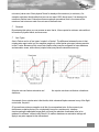
In addition, the magnification levels were disproportionate to real world magnification levels and
did not reflect the area between the tick marks in DSB1. DSB2 used to provide a magnification of
8:1 versus 64:1, this has now been fixed.
6.2
TRACK WHILE SCAN(TWS) / “TWIZ“
Previously, the Target Acquisition Cursor attached itself to targets even with radar lock or
designation broken, or gimbal limits exceeded. This has now been fixed.
6.2.1.1
TWS (Track-While-Scan) Radar Sub-mode
The TWS radar mode has undergone a complete overhaul in how it is mechanized. It should
operate much more like the real thing than ever before. This includes the number of targets it can
track at once (which was previously unlimited), how it builds and maintains track files, how it
dumps them and the azimuth and elevation limits of TWS.
6.2.1.2
How to use TWS (Twiz)
To switch to the CRM-TWS (combined radar mode) sub-mode, the pilot may either hit OSB 2
three times or TMS right to switch from CRM-RWS to CRM-TWS. Upon entering TWS, the radar
azimuth will initialize to an “A2” or 50 degree azimuth scan (25 degrees on either side of
boresight) and the elevation will initialize to a 3-bar “3B” scan.
6.2.1.3
TWS Mechanization
As its name implies, TWS tracks multiple targets while searching for others. It is mechanized to
begin forming track files (triangles, or hollow squares with a tic if you’re using EPAF radar cues)
24
F4-BMS 2.0 Technical Manual
automatically from RWS search hits (solid squares) when the radar receives two hits (meaning
the radar detects something twice) in 6.5 seconds. The radar is able to track 10 targets
simultaneously. Since the radar does not pause on the track files while scanning, the track’s
positions are extrapolated in between updates (when the radar detects them again). If a target is
not updated, i.e., detected in 13 seconds, the radar will dump the track file until the target is
detected again upon which it will rebuild it into a track file. A dump could happen for a number of
reasons including a target moving out of the radar’s current azimuth scan, elevation scan, or
both. Also for example, if the pilot is tracking 10 targets and decides to designate on a search
target, the radar will dump the lowest priority track and automatically upgrade the search target
into a track file. If the radar has not received a hit on a track on its return scan where the track
should be (or rather, where the radar thinks it should be based on the target’s last heading and
speed), the track file will turn from yellow to red to indicate this. When the track is detected again,
it will turn back to yellow. If a track is no longer detected, it will turn red like previously mentioned
and extrapolate for 13 seconds total. The last 5 seconds before the radar dumps the track, the
track will begin to flash. Tracks are prioritized by range and the order in which they were built.
Three scan patterns are available in TWS. They are:
± 60, 2 bar
± 25, 3 bar
± 10, 4 bar
Without a bugged target, the azimuth scan centers on the cursors and elevation is controlled
manually. When a target is bugged, the azimuth is biased to keep the bugged target in the scan
and the elevation is centered on the bugged target. If the antenna elevation is tilted while the pilot
has a bugged target, upon dropping the bug, the elevation scan will move according to what the
pilot commanded to reflect the position set by the antenna elevation controls.
There are two ways to bug targets. The pilot may either slew the cursors over to a track file (or a
search target) and designate or may TMS-right to bug the closest track file. Further TMS-right’s
will step the bug to the next highest priority track file. The pilot may enter STT (Single Target
Track) by TMS-forward on a bug. This will erase all search targets and tracks from the radar,
although the tracks will extrapolate for 13 seconds. If the pilot undesignates (TMS-aft) to return to
TWS, the extrapolated tracks will reappear and the target will be bugged. If TMS-aft is
commanded again, the pilot will drop the bug and the radar will continue to TWS. If TMS-aft is
commanded a third time, the radar will dump all tracks and begin rebuilding tracks automatically.
If TMS-aft is commanded a fourth time, the radar will go back into CRM-RWS.
6.3
NON F-16 HUD SYMBOLOGY
For non-F-16 aircraft, the sim may now be configured to show an AOA indicator that will appear
in the HUD. This AOA indicator has the Greek Alpha symbol. Since most aircraft have this, the
indicator defaults to on. It may be turned off by setting g_bhudAOA to 0.
25
set g_bhudAOA 0
Note: This feature is disabled on the F16.
6.4
VOICE MESSAGING SYSTEM (VMS) / BITCHING BETTY
The VMS - MAL/IND button now plays all VMS words once while holding the push button
(release the button and the litany will stop). Also added a bit to the shared memory to indicate if
the Autopilot is engaged or not. Useful for driving the correct sort of magnetically held toggle
switch for a physical cockpit MISC panel.
VMS – SOUND: Updated sound code to allow the VMS system to play the test message on the
ground, but only if the MAL/IND light is pressed. Code updated to use the proper sample that has
Betty say all the words in her vocabulary once each for the test.
6.5
UHF RADIO FIX
UHF panel controls should only affect the COMM1 UHF radio, not VHF COMM2. UHF function
knob does nothing now; instead the UHF panel channel controls are activated when the AUX
COMM panel CNI switch is in "backup" (per the real jet). The reverse video for transmitting
should work properly in all cases now (it used to only get drawn highlighted properly if the UHF
radio was displayed in line one of the DED).
6.6
ANTENNA ELEVATION
BMS 1.03 changed the way the antenna elevation tracking works. This was done to fix a bug
where the ACQ cursor would occasionally show 0/0 for the altitude limits after an undesignate
command in situations where it should not tilt the antenna down. Study of this bug revealed that
the game code wasn't managing antenna elevation very well. New code makes the antenna
elevation knob the reference value so that for all but STT and TWS (with a bugged target) the
antenna elevation is set to whatever the knob position says it should be. This is how it works in
the real jet as far as we can tell. This gets rid of the situation where the 0/0 radar elevation limit
values were broken so that bug should be gone. It also means that you have a better way to keep
track of the antenna elevation position simply by looking at/feeling the knob position. This also
makes it easier to sync HOTAS control positions to the game. It also, by the way, means that the
knob position can be set independent of the radar mode (if you are in STT and move the knob,
when you undesignate, the elevation will revert to wherever you moved the knob to during STT!).
Also changed is the way "attach" works for SAM AUTO mode. Now the cursor should attach
more readily again but as per a previous fix it will not stay attached if the radar track degrades or
is dropped or if you make a 360° turn.
26
F4-BMS 2.0 Technical Manual
6.7
MAVERICKS
A new variable has been added to allow Mavericks to take 3 minutes for seeker gyro spool up
instead of 5 seconds. This reflects real life and thus the “NOT TIMED OUT” message will
disappear after 3 minutes and Mavericks will be ready to launch. The default setting is “0”, i.e.,
OFF.
6.8
OTHER FIXES / ENHANCEMENTS
The AA radar bar scan indication has been swapped. Instead of showing “B 4” (vertically) it now
says “4 B”. The AG radar SA cue (a “+” sign in EXP/DBS1/2) was previously too large. It is now
half the size it was.
The “New Guy” RWR sound (beep beep beep) no longer plays when a new emitter is detected.
Instead it now plays a short burst of audio of the target emitter instead of that generic new guy
beeping sound. In real life, new guy audio consists of 3 bursts of audio in 1.5 seconds at the PRF
(i.e., sound) of the new emitter. This will be adder later on.
TWS cursor attach bug fixed. Cursor will no longer stay attached to targets when radar lock or
designate is broken, or gimbal limits have been exceeded.
DBS2 magnification corrected to reflect the area between the tick marks in DBS1 mode. DBS2
27
now provides greater magnification (64:1 instead of 8:1).
The Maverick seeker Weapon) MFD has been adjusted. The crosshairs have been tweaked, the
Field-of-view (FOV) box has been increased to the proper size and the 5°, 10°, and 15° tick
marks have been positioned correctly.
Changed the MFD OSB label #3 on the FCR to read "NORM" instead of "NRM".
Changed the heading shown for a bugged target in the MFD to round up or down, i.e., to show
110, 120, 130, etc. instead of 110, 111, 112, etc.
Tweaked the flash rate for the ALOW radar alt and the break-X. They flashed too slow prior to
this fix.
Added EXP FOV to RWS.
Air-to-Ground GM SnowPlow mode has received a significant overhaul to be more realistic. The
following is a brief description of its changes and how it functions. Pay special attention on how to
enable cursor slewing.
Depress OSB 8 next to the SP mnemonic to select the snowplow option. The mnemonic
highlights indicating that you are in the SP mode. SP sighting directs each sensor line-of-sight
straight ahead in azimuth, disregarding any selected steerpoints. In the GM, GMT, and SEA
modes, the ground map cursor will be positioned at half the range selected, i.e., the center of the
MFD. The cursors remain at this range while the ground map video moves, or "snowplows,"
across the MFD. At this point, there is no SOI, and the cursors cannot be slewed. The cursors
can be slewed to a target or aimpoint with the CURSOR/ENABLE switch after you ground
stabilize them by using TMS forward. TMS forward establishes the radar as the SOI and enables
cursor slewing. TMS forward again over a target to command single target track. All cursor slews
in SP are zeroed when SP is deselected. After ground stabilizing, the point under the cursors at
the time of stabilization effectively becomes your steerpoint. All NAV and weapon delivery
steering and symbology, including great circle steering, will be referenced to this "pseudo
steerpoint." Displays return to the previously selected sighting point when SP is deselected. For
example, SP can be used to accomplish an FCR mark on a point 5 nm in front of your position
28
F4-BMS 2.0 Technical Manual
when the steerpoint selected is 40 nm away. It may often be used with IR Mavericks where target
coordinates are not known in advance. Another application of SP is for weather avoidance (not
implemented).
Additionally, the GM range AUTO bumping function is revised in this version. It works more
intuitively now with the range bumping up if the cursor is at 95% of the way up the MFD and
bumping down if the cursor is at 42.5% of the way up the display or less. Note the bump will only
happen if and when the cursor is not being slewed! As a final note, TTG (Time-to-go) has been
added to the GM radar scope when you are in STP mode or SP mode with a ground stabilized
aim point.
Added the missing BATR (Bullets at Target Range) circle for EEGS. It is a 6-mil circle displayed
after the trigger squeeze and the bullet travels the target's range. It disappears after the last bullet
passes the target range (well actually it disappears 1 second after the trigger is released--that is
good enough for the time being). The BATR is nothing more than a record of where the gun
cross has been pointed (corrected for gravity drop). Needs some refinement, but the basic
functionality is there.
The EEGS funnel will now disappear when the trigger is pulled and reappear 1 second after
trigger release.
"X SRM" or "X MRM", where "X" is the number of missiles for that type, are now drawn in missile
override mode (instead of "MSL"). "MSL" is a display thing of BLK 30 F-16s and lower (i.e.,
mainly older software tapes).
Mach number and max g's windows are now not drawn in the HUD when in Dogfight override.
The "SpeedText" (basically the CAS [i think, but doesn't really matter ;-)] speed required to reach
the current steerpoint on time) field is now not drawn in the HUD when in Dogfight override. This
was never realistic.
Attack symbology (missile reticles, ASEC, ASC, DLZ, timers, etc) are blanked on the FCR/HUD
when the master arm switch is in OFF (i.e., weapons safe).
The bar scans (the number of bars in the scan, rather) was incorrect for both ACM 30x20 and
ACM Slewable. 30x20 was corrected from a 5B to a 4B and Slewable was corrected from a 3B to
a 4B.
TMS aft is the only switch action that commands a break lock from an ACM track mode.
Added center-point dot to the gun strafe circle.
Adjusted STRAF in-range cue line to work when within 8000 feet (instead of 4000 previously) to
accurately reflect in-range cue for GU-28 bullet instead of M56.
Minor fixes to HSD symbology to reflect proper size (0.05 is DEFAULT/OFF and 0.025 is halfsize, i.e., ON). We recommend 0.025 for 1600x1200 resolution and 0.035 for 1024x768.
Tweaked ACMI colors/labels a bit to be a little more readable.
29
Fixed the ACM slewable scan search altitude display numbers to show negative numbers and
red when negative. Also fixed the spacing between them so they're not scrunched up together.
Fixed the DLZ in the MFD. It was placed too far low and the Time to Active/Time to Impact
numbers were way too low and to the left.
The lower/upper numbers of the cursor altitude coverage show negative numbers and turns them
to red when they are negative.
In Freeze mode, a circle with a line sticking out is now displayed, instead of an airplane cross.
ILS Command Steering defaults to being on.
Fixed the HSD bugged target symbol (the ]- symbol).
The pre-launch/post-launch missile time prefixes were wrong for the HUD, regarding time-untilactive and time-until-impact. Changed the equations to match those of the MFD, which was
correct. Small, but important realism bug fixed.
Changed the HTS cursor to be twice as fast.
Removed an unnecessary scaling factor that dealt with drag. Previously stores drag was
calculated by DragIndex times ( 18238 divided by aircraft empty weight). Now the stores drag is
just DragIndex.
The AOA Indexer next to the HUD is now operational regardless of the gear being up or down.
This is per the F-16 technical order.
Adjusted blackout/greyout numbers per USAF guide on GLOC and pilot’s input. This should
better simulate a good AGSM and Combat Edge equipment
When Bullseye mode is off, (LISTÆ0, 8 , then 0 to toggle on and off), the bearing and range from
the current INS steerpoint to the radar cursors is drawn in the FCR Bscope and the HSD.
The ACMI recording message, "RECORDING: ++++" that is show at the top of the screen can
now be turned off by checking ACMI Record Msg Off (set g_bACMIRecordMsgOff 1) in the
Config Editor.
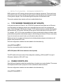
Falconbms.cfg variable: set g_fHSDSymbolSize 0.025
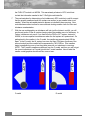
The bullseye circle on the HSD and on the radar was too large. Set the value to “1” if you would
like a smaller bull’s-eye circle (NOT recommended for resolutions below 1280x1024.
Falconbms.cfg variable: set g_bSmallerBullseye 0
30
F4-BMS 2.0 Technical Manual
Default size:
New size:
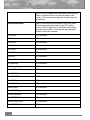
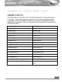
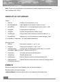
The radio channels in Falcon have received a small face-lift. The functionality remains the same,
but what is being shown on the DED is now a bit more realistic. “Preset” channels are now
displayed instead of the name of the channel function (ie., Tower, Guard, Package1). It is
recommended to not use Presets 11 & 12 when using Internal Voice Communications (IVC) for
multiplayer voice comms. Use caution when using 15, as it will only work out to approximately 30
nm away from wherever you’re taking off from or if you’re close to an airfield. It was originally
designed this way, although not realistic. See the SP3 manual for more information regarding
Multiplayer and Internal Voice Comms.
31
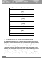
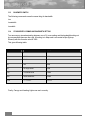
6.9
New DED “preset”
Falcon 4 Channel Function
1
Flight1
2
Flight2
3
Flight3
4
Flight4
5
Flight5
6
Package1
7
Package2
8
Package3
9
Package4
10
Package5
11
From Package
12
Proximity
13
Guard
14
Broadcast
15
Tower
MICRO-MANAGING THE STORES MANAGEMENT SYSTEM
The Stores Management System (SMS) in Falcon has received a complete overhaul. Much of
this work will be somewhat transparent to the user, but the improvements are there nonetheless.
Many of the improvements have been to make the code more consistent, efficient, cleaner, and
more “friendly” in terms of playing nicely with other parts of the Falcon code. The following is what
the end-user will see, when comparing to previous versions of BMS and Falcon.
A long-standing problem with Falcon and it’s SMS, was the fact that it was unrealistic in jettison
procedures—both selective jettison and emergency jettison. Essentially, when jettisoning stores
(weapons), the entire store/pylon assembly was jettisoned from the wings. In reality, the
circumstances of what comes off during a jettison greatly depends on what weapon(s) are
carried, whether or not the aircraft is carrying racks (launchers) or something like a TER (Triple
ejector rack). The basic point is that the wings would essentially be empty of all pylons (excluding
32
F4-BMS 2.0 Technical Manual
AA missile pylons), when the pylons (and the drag!) are actually bolted to the wings and can’t be
jettisoned. BMS has rebuilt the SMS code to allow such differences amongst a wide-variety of
stores and their individual differences. More information about the BMS rack data and how it’s
built can found in the Appendices. Since Falcon is primarily an F-16 simulator, BMS focused only
on the SMS of the F-16 as well as the BMS rack data file only contains store/rack information for
only the F-16.
6.9.1
Selective Jettison (S-J)
The first thing the pilot will notice is some graphical differences. The line box drawn around the
store/pylon(s) are gone, and now replaced by inverse labels, upon when a station’s store/rack is
selected for jettison. The S-J page and the S-J mastermode are selected by depressing OSB 11
adjacent to the S-J label on any SMS page. This will allow the pilot to jettison weapons and racks
unarmed or unguided from selected aircraft stations. Only jettisonable stores will be displayed for
selection. The pilot presses the OSB adjacent to the station displayed on the S-J page. The
selected station’s bottom-most store is highlighted on the S-J page, indicating that it is selected. If
a jettisonable rack is also loaded, it may also be selected on the second depression of the OSB.
A third depression will then deselect all stores on that station. The pilot can preselect a selective
jettison configuration while in S-J mastermode, which will be remembered during mastermode
transitions. The stores are jettisoned using the pickle button when the Master Arm switch is in
ARM. After the stores are released, the highlighted stations are removed from the S-J page and
the associated weapon quantity reads zero. The S-J mode also bypasses any other weapons
settings.
6.9.2
Using the SMS in Combat
Also related to the SMS, is how it functions in combat. Previously, the SMS did not do a good job
at remembering what weapons you called up for a particular mastermode. Now, it should
remember the particular weapon type you select. This applies to all the mastermodes—Air-to-Air,
Air-to-Ground, NAV, Dogfight, and Missile Override. What this means is the pilot can program the
weapons he wants to come up first in a particular mastermode.
6.9.3
Remechanization – Hands-On Missile Select
Depress and Release (D&R) of the Missile Step switch on the sidestick controller provides
hands-on selection of a stores station. When in an A-A master mode, D&R of the Missile Step
switch for <0.5 seconds selects the next stores station in the rotary with the selected weapon
type. The selected station is identified on the SMS Base page by inverse video. Hands-off
changes remain the same.
When in an A-A master mode, depress and hold the missile step switch >= 0.5 seconds to select
the next missile type in the A-A weapon selection rotary. The avionics system automatically
selects the next missile type in the A-A rotary and displays the newly selected weapon mnemonic
adjacent to OSB #7 on the SMS Base page. The missile type (SRM, MRM) will also change on
the HUD if the new missile is a different type.
33
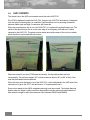
6.10
HUD / AVIONICS
The horizon line in the HUD now extends across the entire HUD FOV.
If the FPM is displaced outside the HUD FOV, it stays in the HUD FOV and has an X displaced
over the symbol indicating that it is unreliable. Flight conditions such as a strong crosswinds,
extreme rudder input and high G maneuvers will cause this.
When the normal horizon line is not in the HUD FOV, it is replaced by a ghost horizon line. The
center of the ghost horizon line is on the outer edge of an imaginary circle with an 8° radius
centered in the HUD FOV. The ghost horizon rotates around the center of the circle to indicate
which direction to pull toward the real horizon.
When the aircraft is in a dive (FPM below the horizon), the dive attitude bars are bent
incrementally. The minimum bend is 8.3° and the maximum bend is 45° (at 90° of dive). Also
note the pitch ladder lines are different.
When the steer point diamond is out of the HUD FOV, it will be displaced in the HUD side of the
shortest turn to get to the STPT and will have an “X” superimposed over it.
Some minor tweaks to the AIM-9 uncaged symbology have been made. The missile diamond
flashes when the target is within maximum range and the missile reticle and missile diamond
flash when the target is within the maneuver zone (between RMAX2 and RMIN2).
34
F4-BMS 2.0 Technical Manual
7
AIRCRAFT
With BMS comes great improvements to other aircraft in the Falcon virtual universe.
For aircraft specific features listed below, the appropriate settings in the aircraft data file need to
be set. These settings are detailed in the BMS Appendices.
7.1
DYNAMIC ROLL INERTIA
The inertial effects of stores on the wings is now factored into the rolling inertia of aircraft. The
effect also takes into account the fuel weight in external tanks. A player will notice that a fully
loaded aircraft will react in a more “sluggish” manner. Both starting and stopping of rolling
maneuvers will need more attention. As weapons are released and fuel is used, this inertia will
decrease.
7.2
TWO ENGINES
The Falcon code now fully supports two engine operations. When flying a two engine aircraft, the
player can control the left, the right, or both engines with his throttle. Each engine has its own
thrust, fuel flow, damage modeling, etc. Be advised that adverse yaw and roll are also modeled
when there is asymmetric thrust!
When an aircraft has two engines enabled, the upper left corner of the screen will display the
current engine selection (BOTH, LEFT, RIGHT) and the rpm of both engines. To cycle between
engines, use the CTRL-O key (known as the CycleEngine command when using different key
mappings). When LEFT or RIGHT is selected, the throttle will only control the rpm of the engine
selected.
For engine startup or shutdown, the procedures are the same as with the single engine operation
except that LEFT or RIGHT engine must be selected.
7.3
F-16
Along with adding two engines, improvements have been made to the single engine functions as
well. For F-16 aircraft using the PW220 Engine:
Engine idle increases from Mach 0.84 to Mach 1.4 when it will be at MIL power from 1.4 and
above.
The afterburner has 3 schedule zones. Area 3 is Segment 5 no light. Area 2 is Seg 1 light only.
Area 1 is no AB available. These are based on various low speed and altitude regimes.
Engine will increase idle speed based on altitude
Engine will increase spool up/down time based on altitude/speed.
35
For aircraft using the GE110/PW229/GE129 Engine
Engine has reduced speed excursion logic modeled. Switches between a higher or lower idle
speed based on mach speed (mach 0.55 being the transition point)
Idle spools up from Mach 1.1 to Mach 1.4 where it will be at MIL power
Idle speed increases with altitude
Reduced AB schedule for low speed/high altitude regimes
F/A-18
7.4
The F/A-18 series of aircraft have the following improvements
New NAV HUD
The HUD layout for the F/A-18 is now modeled. The player will find:
¿
Vertical velocity indicator above altitude.
¿
Alpha, Mach, G, Peak G moved to their correct locations.
¿
AOA bracket set for (6-10 degrees AOA). The alpha display will blank out when the
gear is down and FPM is in the bracket range. Also the cockpit AOA indicator lights will
now match the correct F18 AOA range
¿
Peak Gs will only display if greater than 4 g’s are pulled. If less than 4 g's are pulled, the
g display will be removed when the gear is lowered.
¿
Mach display is removed when the gear is lowered.
¿
A water line indicator will appear when the FPM is constrained or the gear is lowered.
Flap Modes
The F/A-18 aircraft now have AUTO/HALF/FULL flap modes modeled. To cycle modes use the
CTRL-F10 keystroke (or the AFFullFlap key command). A player should only use this keystroke
to control flap settings (the other flap keystrokes should be ignored). When the flap mode is
cycled the flap display will also indicate the current mode.
AUTO is the standard up and away flying mode. After takeoff, CTRL-F10 to AUTO
HALF will allow flaps to blow down under 250 knots to a maximum of 30 degrees. If speed
increases past 250 knots, flaps will raise.
FULL will allow flaps to blow down under 250 knots to a maximum of 45 degrees. If speed
increases past 250 knots, flaps will raise.
36
F4-BMS 2.0 Technical Manual
TEF Scheduling
The F/A-18 aircraft now have the trailing edge flaps scheduled per the -1 manual. The TEFs will
deploy and retract based on both AOA and Mach.
Speedbrakes
The F/A-18 A-D model aircraft will now auto retract the speedbrake when aircraft g is 6 or
greater, AOA is greater than 28, or the gear are down and airspeed is below 250 knots.
Engines
The F/A-18 engines will now spool up to full MIL power when at Mach 1.23 or greater.
F-14
7.5
The F-14 series of aircraft have the following improvements
New NAV HUD
The HUD layout for the F-14 is now partially modeled. The player will find:
¿
Vertical velocity indicator above altitude.
¿
Alpha, Mach, G, Peak G moved to their correct locations.
¿
AOA bracket set for (13-17 degrees AOA). The alpha display will blank out when the
gear is down and FPM is in bracket range. Furthermore, the cockpit AOA indicator lights
will now match the correct F18 AOA range
¿
Peak Gs will only display if greater than 4 g’s are pulled. If less than 4 g's are pulled, the
g display will be removed when the gear are lowered.
¿
Mach display is removed when the gear is lowered.
¿
Waterline indicator that appears whenever the FPM is constrained or the gear is
lowered.
Flap Warning
The F-14 does not have an automatic flap retraction system. If the flaps are extended past 10
degrees and the airspeed is greater than 225 knots, a RDC SPEED warning is flashed on the
HUD. This warning will also appear when a maximum airspeed of Mach 2.4 is exceeded.
Speedbrakes
37
The F-14 A-D aircraft will automatically retract speedbrakes when the throttle is moved to MIL
power or the airspeed exceeds 400 knots.
Engines
The F-14 engines will now spool up to full MIL power when at Mach 1.4 or greater. The engines
will also increase idle rpm speed if the AOA exceeds 18 degrees. Also modeled is the rich
stability cutback. This feature allows only partial afterburner in various low speed/high altitude
flight regimes.
F-15
7.6
The F-15 series of aircraft have the following improvements
New NAV HUD
The HUD layout for the F-15 is now partially modeled. The player will find:
¿
Vertical velocity indicator below altitude.
¿
Alpha, Mach, G, Peak G moved.
¿
True Airspeed (marked with a T symbol) displayed under Calibrated Airspeed.
¿
Peak Gs will only display if greater than 4 g’s are pulled. If less than 4 g's are pulled, the
g display will be removed when the gear are lowered.
¿
Mach display is removed when the gear is lowered.
Flap Retract
The F-15 flaps will retract if a player exceeds 250 knots. If the flaps switch is left down, the flaps
will also deploy again when the airspeed decreases below 250 knots.
Speedbrakes
The F-15 speedbrake will retract if extended and 25 AOA is exceeded. If the speedbrake is left
deployed, it will extend out again when the aircraft is under 25 AOA.
Engines
See F-16 (PW-220, 229).
38
F4-BMS 2.0 Technical Manual
7.7
F-4
The F-4 series of aircraft have a few improvements.
Engines
The engine operating range is modeled along with the possibility of flameout from various low
speed, high altitude, or high AOA regimes (per the -1 manual). The afterburner cutoff range is
also modeled.
39
8
AUTOPILOT
The SP series of executables introduced a much improved 3-Axis autopilot (AP) for realistic
avionics users. There are however some opportunities remaining to improve upon that system.
This version of the BMS executable introduces a significant overhaul to the realistic mode
autopilot.
8.1
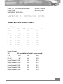
CHANGES FROM SP3
The SP3 autopilot had a tendency to “porpoise” (significant rate and magnitude oscillations of
nose position up and down) in ALT HLD mode. This tendency has been fixed by adding some
damping to the autopilot altitude holding functions. The AP should now meet or exceed the real
jet’s performance of holding altitude +/- 100 feet either side of the selected reference. In doing so,
pitch changes when the jet is close to the selected reference altitude are very much smaller so
you should end up with a rather more “straight and level” experience when selecting this mode.
Roll mode selections are now independent of the pitch mode selection. What this means is that
you can select pitch ATT HLD (attitude hold) and any of the three roll modes. Fixed pitch climbing
turn to waypoint heading?? No problem! Previously the SP3 autopilot would only allow pitch
ATT HLD if the roll modes switch was in ATT HLD also.
Pitch ATT HLD mode completely revised. The new function is able to hold selected pitch much
more effectively while also implementing stick steering as described below. The pitch reference is
now driven from the same reference value used to place the FPM on the HUD pitch ladder. What
this means is that when you engage pitch ATT HLD mode, you should get (near enough) the
pitch displayed in the HUD as the reference value for the AP to hold.
Stick steering implemented. When you have either pitch ATT HLD or roll ATT HLD selected, you
can change the pitch or roll reference angles respectively at any time by merely applying
pressure to the control stick (i.e. joystick). When pressure is released again, the AP will attempt to
hold the new pitch and roll at the time the pressure was released. Stick steering will work for
either axis if it selected, regardless of the selected AP state of the other axis; i.e. if you have pitch
ATT HLD and roll in STRG SEL, you will be able to manually change pitch by direct stick inputs
but not roll (unless you also depress AP Override of course!).
Self-centering pitch mode AP control switch implementation completed. In the real jet, the rightmost AP control switch is a spring loaded self-centering switch. It is held in ALT HLD or ATT HLD
positions by a magnetic capture mechanism. Capturing the switch in either one of these two
positions is what engages the AP. The AP will operate within limits of plus or minus 60 degrees
from straight and level in both pitch and roll axes. If you exceed these limits with the AP
operating, the AP function is suspended but the AP pitch switch is not released from its current
position. In order to re-engage the AP in this case, you must center the pitch mode switch
manually and then reselect the required AP pitch mode to turn on the AP. Also, if certain other
conditions arise during AP operation, the AP will self-disconnect, releasing magnetic hold and
40
F4-BMS 2.0 Technical Manual
springing the switch back to the off/center position. The conditions implemented in the version of
the game are:
¿
Angle of attack exceeds +15 degrees.
¿
Slow speed warning sounds.
¿
Gear handle is placed in the down position.
¿
The AIR REFUEL switch (FUEL panel) is put into the “OPEN” position opening the
refueling door.
¿
There is an FLCS fault detected.
¿
Power is removed from the AP system
¿
The Trim AP Disconnect switch (MANUAL TRIM panel) is placed in the “DISC” position.
¿
The ALT FLAPS control (FLT CONTROL panel) is placed in the “EXTEND” position
locking the trailing edges flaps in the down position.
¿
The manual pitch override control (MANUAL PITCH panel) is placed in the “OVRD”
position.
There is now code in the BMS exe series that should fix the infamous “pitch up on landing after
using autopilot during flight” bug. This bug would only happen in SP3 if you got the AP into pitch
hold mode, which wasn’t easy since you’d have to cycle the left AP switch at least once all the
way around to ATT HLD before attempting to put the right (pitch) switch into ATT HLD or it
wouldn’t engage that pitch hold mode. By the way, this bug also affected in-flight operations if
after pitch hold mode was entered and left you subsequently allowed speed to decay and
commanded higher angles of attack (say when you are in a turning fight and incautiously let your
jet fall well, well below corner); in this case you would have seen the jet snap into a deep stall as
the bug took effect.
41
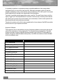
9
BMS AP OPERATION SUMMARY
The following charts depicts the main functions of the AP in the BMS executable.
Switch
Position
Remarks
Roll mode
(left)
HDG SEL
(up)
When the autopilot is on, placing the roll mode switch in this position causes the
AP to turn the jet towards the heading currently selected in the HSI gauge (center
console).
ATT HLD
(center)
When the autopilot is on, placing the roll mode switch in this position causes the
AP to hold the current bank angle at which the aircraft is flying. Stick steering for
the roll axis is available with this setting.
STRG SEL
(down)
When the autopilot is on, placing the roll mode switch in this position causes the
AP to turn the jet towards the currently selected in the navigation system (note
that this may be a steer point, mark point or equivalent).
ALT HLD
(up)
Placing the switch in this position turns on the AP function. The AP will attempt to
hold the altitude at which the jet is currently flying. Roll mode is determined by the
roll mode switch.
OFF
(center)
Placing the switch in this position turns off the AP. All AP control is terminated.
ATT HLD
(down)
Placing the switch in this position turns on the autopilot. The AP will attempt to
hold the pitch attitude at which the jet is currently flying. Stick steering for the pitch
axis is available with this setting. Roll mode is determined by the roll mode
switch.
Pitch
mode
(right)
Note that the roll mode selection is independent of pitch mode selection. The AP is only on and
engaged when the pitch switch is in either the ALT HLD or ATT HLD position. When the AP is on
the roll mode is determined only by the position of the roll modes control switch.
Note that movement of the roll mode switch when the AP is off (pitch mode switch in center
position) has no effect on aircraft controls.
42
F4-BMS 2.0 Technical Manual
9.1
GUIDELINES FOR AP USE
Keep in mind that the AP manages pitch and roll inputs for you but you retain control of the
throttle. Particularly with pitch ATT HLD modes, you will quickly see the AP disconnect because it
exceeds available angle of attack if too low a power setting is selected via the throttle.
Use caution when engaging the pitch ATT HLD mode AP with a negative pitch angle. The jet will
happily fly you into the terrain if you run out of altitude. The VMS system will of course still warn
you that this is about to happen.
The AP Override control is always available if you want to take temporary control of the jet while
the AP is on and engaged and you have something other than pitch and/or roll attitude hold
modes selected. I.e. to change altitude when you have the AP in ALT HLD mode, depress the
AP override, dial in the new required altitude with the stick and then release the AP override.
For both pitch and altitude hold modes, the AP will take a little time to “settle” at the requested
altitude or pitch; sometimes this can be a minute or more. This time will likely be on the longer
side for higher pitch angles and/or lower power (throttle) settings. If you select a high pitch angle
with relatively low power and/or a hefty load out, the AP may not be able to settle at the
requested pitch reference angle before exceeding AP operating limits and self-disengaging. This
may look like the AP is not working but in practice you just requested it to hold a flight condition
that is not within the AP’s flight envelope.
If it looks like the pitch mode AP switch appears not to move from the center position when you
try to turn on the AP, take this as a hint that one of the conditions than causes the self-centering
AP switch to self-center applies! With a real switch you’d try to move it and it would spring back.
The game graphics do move the switch but it springs back in one frame so it may appear not to
have moved at all.
43
10
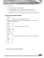
10.1
INPUT DEVICES
NATIVE TRACKIR SUPPORT
FalconBMS natively supports the „TrackIR“ headtracking device via its remote interface, which
enables much easier panning. You have to start the Naturalpoint application prior to running
Falcon. Once in the game, you may activate the TrackIR support for 2D and 3D cockpit
seperately in the 'View Control" config settings (please refer to the relevant chapter in this
manual).
You are able to deactivate TrackIR at any time by using the Naturalpoint hotkeys (F9 by default),
or by just breaking the LOS between the TrackIR emitter/receiver and the „dot“ which is tracked
by it. After about 1 second, view control should migrate to the POV keys/keyboard. Once you
enable TrackIR again (or restore LOS between tracker and dot) control should switch
immediately to the TrackIR.
While in the 3d cockpit, panning will work just as with the TIRF4 application (an external program
that enabled TrackIR support for the SP3 executable).
Also added was support for the 2d cockpit. In this mode, the headtracker behaves a bit like a
POV hat, which means that if you look up, the program will emulate an 'up' press on the POV hat.
If you look left, the program will emulate a 'left' POV hat press etc. The repetition rate of these
emulated keypresses can be configured by the g_nTrackIRSampleFreq variable. The units of this
variable is in milliseconds, it defaults to 512 milliseconds (about 2 emulated keypresses per
second). The area where the TIR input will be interpreted as 'POV-press' can be configured as
follows:
44
F4-BMS 2.0 Technical Manual
This is a view of the TIR receiver. As long as the dot stays in the 'neutral' zone (if you look
directly at the receiver) no change in the 2d cockpit will happen. The two configuration variables,
g_fTIRPitchPercentage and g_fTIRPitchPercentage are symmetric to the 'zero' point.
10.2
CHANGES TO THE HANDLING OF INPUT DEVICES
We have quite substantially reworked the way Falcon4 handles input devices, with the goal to
make it as flexible as possible in respect to supported in-game analogue axis as well as to the
different controller configurations employed by Falcon users. To manage all new options, an
additional 'Advanced controller' window was added, which can be reached through the controller
tab of the setup window. Click on the 'Advanced' button located beneath the key mappings to
access this new window.
The advanced button used to access the advanced controller screen
45
¿
Mapping your Joysticks
Click on the 'Controller' drop down box in the setup-controller tab in order to select your flight
control device, which is the joystick were your pitch and bank (x/y) axis are located. Please note
that this will be the only device that plays any force feedback (FFB) effects !
Falcon will try to autodetect pitch, bank, yaw (rudder) and throttle axis located on that device; if it
succeeds, the respective bars will turn coloured and will start representing the current value of
this axis. Do not worry if no axis are detected, or if Falcon picks up the wrong ones, you can
configure this in the advanced controller screen.
Falcon will pick up the first 32 buttons on each controller, but will only light the buttons in this
screen in response to the first eight buttons pressed on the primary flight control device. However
the text-readout below the keymappings should work for each button.
If the mapped device supports FFB it will be enabled by default, and you should get immediate
feedback (the 'gunfire' effect) on button presses.
10.2.1 The Advanced Controller Screen
You can reach this screen by clicking the 'Advanced' button located beneath the key mappings in
the setup-controller tab.
This window has 4 tabs (categories) named 'View control', 'Flight control', 'Avionics control' and
'Sound control', however, before these tabs are described in detail, some words about the
handling of analogue axis in Falcon is in order:
¿
Analogue Axes in Falcon
Maybe the most important fact first: you will only be able to map one in-game axis to one
'physical' analogue axis ! So if you, for example, already have mapped the mousewheel axis to
the viewzoom axis, you will not be able to use it to control FOV too !
¿
Axis properties
Axis in Falcon have three properties that may be configured in the UI by the user:
¿
Deadzones
A deadzone is a region around the center position of the axis in which motion is ignored. Hence,
the axis always reports '0' while in a deadzone. Deadzones are always symmetrical to the '0'
point of an axis.
¿
Saturation
A saturation zone is a zone of tolerance at the minimum and maximum of an axis. An axis value
within this zone is reported as the minimum or maximum value. The purpose of this is to allow for
axis (usually of the cheaper ilk) that report values less (or greater) than their maximum (or
46
F4-BMS 2.0 Technical Manual
minumum) value even if their physical 'throw' is already at the maximum (or minimum). An
example might be a throttle slider that just can not report 100% thrust even if it is already at its
maximum positive travel. Saturation zones are always symmetrical, that is, the zones at the
maximum and minumum ends of an axis are of the same size.
¿
Reversal
By activating this option you can reverse an axis, that is, it then reports its minimum value while at
its maximum physical travel, and vice versa.
¿
Axis Types
Axis in Falcon can be of two types: 'unipolar' or 'bipolar'. The difference between the two is that
unipolar axis report value in a non-negative range only, while bipolar axis report value symmetric
to the '0' value. Because of this, some axis (bipolar ones) may be configured to have deadzone
and saturation zones, while others (unipolar ones) may have a saturation zone only.
A bipolar axis can feature saturation and
deadzone
An unipolar axis does not feature a deadzone
An example for an unipolar axis is the throttle, while a classical bipolar usecase is any of the flight
control axis, like pitch.
Of course there exists an exception to all this: the mousewheel axis. As the mouse is per
definitonem a relative device (it is not physically bound to a certain point - desktopsize/mouselength-cable/radio-range does not count) the absolute coordinates have to be
gathered 'in software', without using DirectX. So neither deadzone nor saturation settings will
apply to any axis mapped to the mousewheel.
47
10.2.2 View Control Tab
This tab is concerned with the various ways to influence view direction in the Falcon world.
The View Control Tab of the advanced controller screen
¿
FIELD OF VIEW (FOV) AXIS
This axis moves the field of view inside its specified minimum and maximum values. You can set
these ranges in the falconbms.cfg file. Should this axis be mapped to the mousewheel, then you
will be able to reset it to its default value by pressing the 3rd mouse button (usually the wheel
itself). This axis works both inside and outside of the cockpit.
48
F4-BMS 2.0 Technical Manual
¿
VIEW ZOOM AXIS
This axis controls the zoom range when viewing an object. Naturally, it only works while in
outside views. If this axis is mapped to the mousewheel, you will be able to reset the zoom range
to a default value (specified by the 3d model currently in focue) by pressing the 3rd mouse button
(which is usually the mousewheel).
¿
MOUSELOOK SENSITIVITY SLIDER
By manipulating this slider you can configure the sensitivity of the mouseview, both inside and
outside of the cockpit. The more left the slider is, the less sensitive the view will be.
¿
KEYBOARD / POV PANNING SENSITIVITY SLIDER
This slider lets you configure the panning speed when keyboard or POV inputs are used. The
SP3 (and default) sensitivity value is almost on the extreme left.
¿
MOUSEWHEEL SENSITIVITY SLIDER
The last of the sliders on this page lets you set the sensitivity of the mousewheel axis (provided
you have one).
¿
3D CLICKABLE COCKPIT DEFAULT
Besides sporting one of the unwiedliest names of all Falcon options, this checkbox sets the
default mode of the 3d clickable cockpit.
The 3d cockpit can be in one of two modes: clickable or pannable.. in clickable mode, the
mousepointer is always visible, the left mouse button is active and can be used to activate
buttons etc.. you can still pan by pressing (and holding) the right mouse button. In pannable
mode, no mouse pointer is visible, and the left mouse button has no function. You are still able to
act on buttons etc by pressing the right mouse button, moving the (now visible) cursor over the
button of interest and clicking the left mouse button.
You can toggle between these modes by pressing the mouse button #4 (provided your mouse
features one), or by mapping and pressing the ToggleClickablePitMode command.
An additional note about the mouse.. if it is NOT mapped to any analogue in-game axis, the
mousewheel (if available) will send FOV-increase/decrease commands, and the middle mouse
button (in most cases, the depressed mouse wheel acts as an additional button) will reset the
FOV to its default value. Once the mousewheel is mapped to an analogue axis, the middle
mouse button will either reset an axis to its default value, or just recenter it.
49
¿
ENABLE CUSTOM AXIS SHAPING
This checkbox is a bit oddly placed since it is not really related to view control. By activating it you
can tell Falcon to ignore any deadzone and saturation settings and instead read the axis 'shape'
from a file supplied by an external application. WIP.
¿
ENABLE MOUSELOOK
Using this button you can enable the mouselook mode introduced with the BMS releases. Please
note that it is not possible to inverse mouse axis direction.
¿
TRACKIR
You have to activate the naturalpoint software before starting up Falcon ! If you fail to do so, the
TrackIR related buttons will never light up, and you will be unable to change TrackIR related
options ! You can enable 2D and 3D TrackIR support independently of each other, so it is no
more required to activate 3d TrackIR for 2d TrackIR to work. Should initialization fail, then the
button will not light up but stay dark instead. Please note the additional TrackIR configuration
options in the falconbms.cfg file, which can be accessed by the BMS configuration editor. See the
TrackIR chapter for a description of these options.
¿
CUSTOM AXIS SHAPING
This button allows Falcon to load custom axis 'response curves' from a file generated by an
external program. These response curves allow the user to change an axis' input characteristics
to a nonlinear mode. This operation is sometimes also referred to as 'axis shaping'. The external
program needed will be released at a latter date.
¿
ENABLE FORCE FEEDBACK
This button allows you to enable or disable force feedback effects on your flight controller. This
button will only light up if Falcon has detected a force feedback joystick as your flight controller,
otherwise it will stay dark all the time. If you disable force feedback, the joystick should enable
autocentering, that is, it should emulate springs using its actuators, but it should not play any
additional effects. The playback of the "stall" Force Feedback effect is deactivated while the
combat autopilot is active.
50
F4-BMS 2.0 Technical Manual
10.2.3 The Flight Control, Avionics Control and Sound Control Tabs
These three tabs are going to be described together as the controls located on them are exactly
the same, the only thing that changes are the axis the controls operate on. These tabs provide a
list of all available in-game axis, where, depending of the nature of the axis, each of these axis
may have one of the following controls:
The Flight Control tab shows mapped axes and axis value bars.
51
¿
A drop down box where you can select the physical axis you want to map it to
¿
A 'value bar' (located to the right of the axis name) that shows the current value of the
analogue axis.
¿
A deadzone drop down box presents you 4 options: 'Small' 'Medium' 'Large' and 'Huge'.
'None' means exactly that, no deadzone is applied to the physical axis. 'Small' applies a
deadzone of 1% the size of the physical travel to either side of the '0' point, while
'Medium' enlargens that size of 5%. 'Large' applies a 10% deadzone, and 'Huge' makes
it a whopping 50% !
¿
And a saturation drop down box that contains 4 options: 'None' 'Small' 'Medium' and
'Large', where 'Small' specifies a saturation zone size of 1% of the physical travel,
'Medium' sets 5% and 'Large' applies 10%.
Please note that, as a consequence of the "One physical axis per in-game axis" rule, the
selection of axis in the listboxes get smaller the more axis you map. If you want to exchange the
mappings of two axis you will have have to temporarily map one of them to the keyboard. in order
to select it in the other listbox.
¿
FLIGHT CONTROL TAB
Here the additional controls in the flight control tab are going to be described:
Note that you can not assign pitch and bank axis in this tab, as this selection has to be done in
the 'original' controller screen. You can, however, edit the deadzones of the pitch and bank axis.
¿
ADDITIONAL NOTES
The changes done in the advanced controller screen are saved partly in the playeroptions save
file (has the extension .pop) and a new file called "axismappings.dat", which both are located in
the /config subfolder of your Falcon4 install. If you want to clear all your mappings, either simply
delete this file or select the keyboard as primary flight controller in the 'original' controller screen.
In addition, the optional axis response curve information is stored in a file called 'axiscurves.cal'.
¿
CUSTOM AXIS SHAPING
There exists an external program that lets the user configure the response curve of any in-game
axis directly via directX. Because of this, all deadzone and saturation settings done for this axis in
the controller UI will be disregarded. To enable custom axis shaping, activate the checkbox in the
'View control' tab. If it does not light up it means that an error occured while reading in the
axiscurve file.
52
F4-BMS 2.0 Technical Manual
¿
CHANGES TO THE JOYSTICK BUTTON ASSIGNMENTS
As now up to 16 devices with up to 32 buttons are supported the button mapping had to be
slightly changed as well: In the keyboard mapping files (*.key in the /config folder of your Falcon
install), button IDs 0-31 belong to the first enumerated controller (the one with the trailing '0' in its
description in the Falcon UI), 32-63 belong to controller #2 etc. If all possible joysticks and buttons
are used the total is 512 buttons, which opens up the possibility for cockpit builders to forego
traditional keypress emulation and directly map via directX buttons, however please note that you
will have to emulate 16 joysticks then ! (For example, you can not assign any key to button #64 if
you do not have at least 3 joysticks connected !)
¿
KEYBOARD MAPPING RESETS TO 'LAPTOP' IS FLIGHT CONTROL IS SET TO 'KEYBOARD'
This is a somewhat peculiar feature of the original code, that nevertheless can be quite irritating.
¿
ANALOGUE THROTTLE CUTOFF
We have enhanced the implementation of the throttle idle cutoff value. By setting the
g_bUseAnalogIdleCutoff falconbms.cfg variable to '1', you may change the idle cutoff throttle
value by pressing the 'AB detent' button in the controller screen with the RIGHT mouse button. A
RED line will show the selected value. Please take care to set this value LOWER than the 'AB
detent' value ! This feature is mainly of interest to cockpit builders who wish to adjust the
simulation to their existing hardware. Note that currently this value (as the AB detent value)
applies to BOTH engines in 2-engined AC.
¿
NOTES ON SPECIFIC IN-GAME AXIS
Here some special notes on in-game axis will be listed.
¿
Pitch
¿
Bank
¿
Yaw
¿
Throttle
Please note that you may not map the mouse wheel to this axis.
¿
THROTTLE2
The right engine throttle can only be used AFTER the left engine throttle has been mapped to an
axis ! The reason for this is that the left engine throttle is the default throttle for single engine
planes ! Please note that you may not map the mouse wheel to this axis.
53
The throttle value bar reflecting dual analogue mapped throttles.
¿
PitchTrim
¿
BankTrim
¿
YawTrim
¿
Brakes
¿
Antenna Elevation
¿
Cursor X
¿
Cursor Y
¿
Range Knob
¿
Comm 1 Volume
Not implemented. This axis scales logarithmic. To use the axis effectively, either change the
axis responiveness curve or use logarithmic potentiometers in your joystick.
¿
Comm 2 Volume
Not implemented. This axis scales logarithmic. To use the axis effectively, either change the
axis responiveness curve or use logarithmic potentiometers in your joystick.
54
F4-BMS 2.0 Technical Manual
¿
MSL Threat Volume
This axis scales logarithmic. To use the axis effectively, either change the axis responiveness
curve or use logarithmic potentiometers in your joystick.
¿
Threat Volume
This axis scales logarithmic. To use the axis effectively, either change the axis responiveness
curve or use logarithmic potentiometers in your joystick.
¿
HUD Brightness
¿
Reticle Depression
FoV
This axis is deactivated if either actioncam or the exit menu is active.
¿
View Zoom
¿
Interface Volume
Not implemented. This axis scales logarithmic. To use the axis effectively, either change the
axis responiveness curve or use logarithmic potentiometers in your joystick.
55
11
11.1
2D / 3D COCKPIT
3D CLICKABLE COCKPIT
A simple but functional 3D clickable cockpit system has been implemented. The list of clickable
buttons is contained in 3dbuttons.dat. This file should be placed in your cockpit directory. In this
release, the included dat file is designed for Aeyes f-16 3d cockpit. Currently most ICP, DED and
MFD buttons have been implemented, but not all.New dat files can be written for other cockpits
and other aircraft. Dat files for other aircraft should be placed in the appropriate aircraft's cockpit
directory.
11.2
COCKPIT AUTO SCALING
With the g_bCockpitAutoScale set to 1, if you select a resolution without a corresponding cockpit,
Falcon will attempt to scale the next best cockpit. If using 1600 resolution, if no 1600 cockpit is
found, Falcon will look for the existance of a 1280 cockpit, and will scale it up to 1600. If no 1280
cockpit is found, the 1024x768 cockpit will be scaled to 1600. If using 1280 resolution, if no 1280
cockpit is found, Falcon will look for the existence of a 1600 cockpit, and will scale it down to
1280. If no 1600 cockpit is found, the 1024x768 cockpit will be scaled to 1280.
When g_bCockpitAutoScale is enabled and 800x600 or 640x480 is selected, the 1024 cockpit
will be rescaled to that resolution. Font size may be an issue at these resolutions.When the
resolution 1280x1024 is selected, the pit will be scaled to 1280x960 and a black bar will be drawn
across the bottom 1/16 of the screen.
11.3
MOUSE SCROLL WHEEL AND MIDDLE MOUSE BUTTON
You can now use the scroll wheel and middle mouse button in Falcon. By default, the wheel will
control the FOV increase and decrease functions. By default, the middle mouse button (or scroll
wheel click) will set the FOV to default. Note, this will only work if the mouse wheel is NOT
mapped as an analogue axis!
The behavior of the scroll wheel and middle mouse buttons can be modified by adding the
following lines to your falconbms.cfg file:
set g_sScrollUpFunction "<command>"
set g_sScrollDownFunction "<command>"
set g_sMiddleButtonFunction "<command>"
Where <command> is the name of the command you wish to execute as listed in your
keystrokes file.Each increment of the scroll wheel will cause the corresponding command to be
executed once. Default Values:
56
F4-BMS 2.0 Technical Manual
set g_sScrollUpFunction "FOVDecrease"
set g_sScrollDownFunction "FOVIncrease"
set g_sMiddleButtonFunction "FOVDefault"
11.4
ADJUSTABLE FOV
You can now adjust the field of view in game. This has multiple uses. Increasing the FOV can
dramatically increase perception of speed, and can be used in the virtual cockpit to see more of
the cockpit. Decreasing the FOV allows closer inspection of far away objects, and allows closeup
views of the MFD's in the virtual cockpit.
The following keystrokes can be added to your keystrokes.key file:
¿
FOVIncrease: Increases the field of view by the number of degrees set by FOVIncrement:.
¿
FOVDecrease: Decreases the field of view by the number of degrees set by FOVIncrement.
¿
FOVDefault: Sets the field of view to the default of 60 degrees.
FOV is retained when switching from external to internal views. Stick input will remain constant,
regardless of FOV.
11.5
OTHER ADDITIONS TO THE 2D COCKPIT
In the panel declaration of the .dat file, you can now use "mfd3", "mfd4", "osb3", "osb4" in the
same way you would use "mfdleft". Please refer to the Appendices for more information.
The new keystrokes for jumping to the backseat etc are: SimToggleRearView and
SimToggleAltView. SimToggleRearView jumps to panel 5100, while SimToggleAltView will jump
to the template defined in the manager info of the .dat file with "altpanel <panel number>;"
Cockpits can now be debugged to a certain extent by the use of the variable
"g_nShow2DPitErrors " in your config file. Setting this value to 1 shows only critical errors, and
setting it to 2 shows all errors. Errors will only be displayed when the simulation in run in
windowed mode “F4-BMS.exe -window".
VG colors are now not see through on transparent panels. You dont have to do anything to
implement this, as it will now just work.
The cockpit resizer has had an overhaul. Any pit can now be scaled to any resolution. At all
resolutions, the resizer now has a predictable order of pit searching. So, if you wanted to rescale
your pit to 1024, simply rename 10_ckpit.dat. Non-standard resolutions such as 1920x1440 will
also be scaled to correctly now. The order is:
57
¿
Aircraft specific native resolution pit
¿
Aircraft specific higher resolution pit
¿
Aircraft specific lower resolution pit
¿
Default native resolution pit
¿
Default higher resolution pit
¿
Default lower resolution pit
Finally, the method of forcing a cockpit resolution has now changed. Instead of the multiple
confusing lines and scale, there is one variable g_nForceCockpitResolution that should be set to
640, 800, 1024, 1280 or 1600. There is little need for this now though with the new auto-resizing
code.
Cockpit rescaling looks almost perfect now. This is done by addign filtering on the cockpit
textures. If you want to disable pit filtering for some reason, add "set g_bFilter2DPit 0" to your
config file.
11.6
OTHER ADDITIONS TO THE 3D COCKPIT
New 3d cockpit code is now introduced. It is enabled by adding set g_bUseNew3dpit 1 to
falconbms.cfg
This will disable old style line indicator needles, and enable new code to drive instruments via
DOF/Switch nodes. The Idea is that all needles are 3d objects rotated under new 3d pit DOFs
and new lights are driven now under new 3d pit switches. Some instruments need more than two
DOFs to operate. For example, the ADI ball uses 2 DOFs for pitch and roll. The HSI uses a lot of
axes to operate, as per real life. The hard-coded limit to the number of DOFs/switches has been
expanded from 127 to 255. All instruments are now aligned/scaled to F16 instruments. Modelers
will use the new BMS XDOF and XSWITCH nodes to control/finetune instruments for other AC
types. This can be externalised to a text cfg file in the future. For now, the new F-16 3d pit for
BMS is not ready for public consumption, this information is mainly for 3d modelers that are
familiar with making 3dmodels/pits for Falcon.
As a "bonus", the old, jerky dynamic pilot head movement was rewritten so as to not disort 3d pit
geometry.
set g_b3dDynamicPilotHead 0 to set g_b3dDynamicPilotHead 1 in f4-bms.cfg to experience
a similar effect to that of the old DID EF2000 simulation.
58
F4-BMS 2.0 Technical Manual
12
12.1
ADDITIONAL FIXES / FEATURES
MISCELLANEOUS
¿
Added multiple fields to the player's logbook.
¿
Tactical Reference will now cycle through the skins when you select/reselect the model. On
the pull-down menu, select your aircraft. To cycle the texture set (if there are additional
ones), just reselect the same aircraft from the pull-down menu.
¿
The Munitions Loadout Screen now has a Change Skin button. If pressed, the skin set will
cycle through the available skins. Whatever skin is displayed will be the skin chosen for the
flight of aircraft in TE and Campaign. Note: this only affects the players flight (1-4 aircraft)
The other squadron aircraft will retain their original skins.
¿
FAC. If you are on a On Call CAS (or similar mission CAS, BAI, INT), you can now use the
AWACS menu "Check In" command as a FAC. If a target is ready, the FAC will give you
vectors and a cleared hot call. If no targets are currently available, you will instructed to hold
at CP Alpha (just hold at one of your target waypoints). In the campaign, as a target is found,
you will be vectored to that target. When vectored, you need to respond with "Wilco". When
finished, use Check Out to end your station time. If Check In is used when you are not
tasked on an appropriate A/G mission, AWACS will reply "Unable".
¿
The campaign was not properly targeting various strategic type targets (factories, HQ
buildings, ports, power plants, etc.). If the sliders are set for these types of missions, and the
player is on the offensive, these targets will be scheduled for attack.
¿
Fixed A/G designate bug where the lateral range from the target was incorrectly determined.
Now slant and lateral range work correctly together.
¿
Campaign waypoint speeds are now a direct conversion from the database. The Unit>movespeed is in Kilometers (PER MPS) and is then converted to NM by the waypoint
code. Previously, the code was subject to various percentage calculations that made it
difficult to accurately set the desired waypoint speeds. The percentage reductions have
been removed and now what is entered in movespeed using F4browse will be what the
waypoint speeds are set. Also note that Falcon does a KCAS conversion of the waypoint
speed to account for differences in waypoint altitudes. If the DB is set in KM to give 350
knots after conversion, that 350 knots is the Sea Level speed. The KCAS conversion will
reduce that speed in the waypoint boxes per altitude. Also the waypoint error checking code
is now based on a percentage of movespeed (30% above or below).
¿
Sensorfusions Radian errors: There were some significant errors in calculations that are now
fixed. Fixed for helo digi sfusion as well.
¿
AI gun sound changed to gun loop for normal gun firing sound not "bump bump". The vulcan
end .wav file that was being used for the AI has been changed to the normal gun loop. Now
the AI gun will actually sound like a gun.
59
¿
AIM-9x’s are now available in Fighter Sweep.
¿
Tankers will now no longer make impossible turns except when they need to fudge the turns
in order to land. This “ex-F-15 driver” 7-g turn was very noticeable in multiplayer—the tanker
would yaw through the turns. After each human took on gas and finished, the tanker would
execute this turn back to his first track point when ownership of the tanker transferred to the
next human, thus making the entire flight chase him down again. Now, the tanker will turn
slightly, but the entire flight should be able to stay with him while ownership is transferred.
Also, hooking up to the boom should be easier. Pitch and roll limits (for the tanker) for
connecting to the boom were very small. Since they are not needed, they were removed.
Prior to this fix, it was nearly impossible to connect to the boom in a turn because of these
limits. You could refuel in a turn and stay with the tanker provided you had connected to the
boom when he was straight and level.
¿
The padlock color now matches the selected HUD color.
¿
Plane and Loadout configurable using text file: create m.ia (Mud Moving) and/or f.ia (for
Fighter Sweep) files in the campaign/save subfolder. Open with Notepad and edit according
to the following example (made for the A-10 in Mud Moving):
# Use F4Browse to find Plane Units (!) and Weapon IDs
#####################################################
# Own plane (Unit Information) Example: A-10
1 type
3 subtype
1 specific
#####################################################
# Weapon loadout: WeaponID (Weapon No.), WeaponAmount
#Loadout Hardpoint 0
62 W0
117 C0
#Loadout Hardpoint 1
12 W1
1 C1
#Loadout Hardpoint 2 (empty on A-10)
60
F4-BMS 2.0 Technical Manual
#71 W2
#19 C2
#Loadout Hardpoint 3
227 W3
3 C3
#Loadout Hardpoint 4
19 W4
3 C4
#Loadout Hardpoint 5
6 W5
3 C5
#Loadout Hardpoint 6 (empty on A-10)
#71 W6
#19 C6
#Loadout Hardpoint 7
81 W7
3 C7
#Loadout Hardpoint 8 (empty on A-10)
#215 W8
#1 C8
#Loadout Hardpoint 9
64 W9
3 C9
Use the # for any comments. Save the file and load Falcon. Enjoy.
¿
1600x1200 and 1280x1024 splash screens have been enabled.
¿
Loading of cockpit settings now also reloads the upper MFD.
¿
Eye Fly works again.
¿
Landing AI planes won’t use afterburner when drag chute is deployed.
61
¿
Swapped X/Y coordinates in Radio Messages.
¿
Saving briefing as text or printing it also includes some TABbing now.
¿
Set g_bBriefHTML. If set together with “set g_nPrintToFile 1”, this creates HTML-based
mission briefings when clicking the PRINT button in a briefing. Such briefings will look much
better than the old briefing.txt file, are easier to print and can be formatted according to your
taste (just edit the style.css stylesheet found in the /briefings subfolder or even hack the *.b
briefing templates in the campaign/save fodler to add your custom tags…).
NEW KEYSTROKES
12.2
¿
OTWToggleFlapDisplay
Flap position display now defaults on for manual flap aircraft. Prior to this release, the flap
position output was accessed through g_bShowFlaps. The code has been changed to default the
flap position indicators to ON when flying a manual flap aircraft. This flap indicator is also now
controlled by a keystroke to turn it off/on.
¿
OTWToggleFlapDisplay -1 0 0XFFFFFFFF 0 0 0 1 "Flap Display Toggle"
Set that at the end of your keystrokes.key file then Go into your Setup->Controllers tab and map
this keystroke to whatever key you wish in Falcon. This will now allow you to turn off/on the flap
display for manual flap aircraft.
¿
SimRandomError
Immediately generates a random aircraft system failure. Good for emergency procedures
training: You know that something will break – but you don’t know what.
Keystroke currently not assigned/mapped. Edit your config/keystrokes.key to add the following
line:
¿
SimRandomError -1 0 0XFFFFFFFF 0 0 0 1 “Sim-Random Error”
You can then assign any key to the command from the Falcon Setup screen.
12.3
WINAMP SUPPORT
The user is able to control the popular WinAmp media player from inside the simulation, either
through keyboard commands or through the ICP. However only basic functionality is supported.
To activate WinAmp support, check the 'WinAmp' checkbox in the BMS configuration editor. Here
you can also specify the initial WinAmp volume, which is set to 80% by default. You will also have
to startup WinAmp and load a playlist (or a single file) before entering the 3D part of Falcon.
WinAmp versions 2 and 5 are supported without the need for plugins, WinAmp 3 will need a
plugin called 'wa2mgr'.
62
F4-BMS 2.0 Technical Manual
Inside the 3D, WinAmp can be controlled either through keyboard commands or through the ICP.
The supported actions are:
Command
The associated keyboard callbacks ICP
Start Playback
WinAmpStartPlayback
Stop Playback
WinAmpStopPlayback
Toggle Playback
WinAmpTogglePlayback
DCS SEQ
Previous Track
WinAmpPreviousTrack
DCS UP
Next Track
WinAmpNextTrack
DCS DOWN
Volume Up (1%)
WinAmpVolumeUp
ICP NEXT
Volume Down (1%) WinAmpVolumeDown
ICP PREV
To control WinAmp through the ICP, you will have to press the LIST button, then twice the 0 ICP
button. The DED will change to show the name of the currently played file, if no WinAmp window
was detected, the DED will show an error message. Playback can be toggled through the DCS
SEQ button, volume can be controlled through the ICP PREVIOUS/NEXT buttons, the
next/previous track can be selected with the DCS UP/DOWN buttons.
12.4
DISPLACEMENT CAM
This feature makes the 'orbit cam' camera move around slightly, simulating the relative motion of
whatever airborne vehicle the orbit cam is located on. This feature needs to be enabled in the
falconbms.cfg file (either through the config editor or by enabling "g_bEnableDisplacementCam"
manually. Once this is done, you can toggle it temporarily by pressing the
"ToggleDisplacementCam" keypress.
12.5
AIR TRAFFIC CONTROL - NEW TRAFFIC CALLS
Once you call inbound on approach to a field, ATC will now call out traffic such as "Cowboy 11,
traffic 2 O'Clock 4 miles." The traffic must be a possible traffic conflict to your plane or it will not
be called out. Once ATC calls traffic out to you, it will continue to update you with that traffic as
long as it remains a possible conflict. If you find the traffic, or just want ATC to shut up about the
traffic, select the "Traffic In Sight" under the Tower menu. ATC will stop calling that specific traffic
out to you unless it becomes a possible conflict again. ATC will not call out aircraft in your own
flight.
63
Known issues: ATC speaks fairly slow in Falcon4. If there are lots of aircraft, and ATC is giving
lots of vectors, the buffer can get backed up. When traffic is called out, it may have already
moved from the location the traffic call was calculated for. If you have text display on, you will see
the traffic call at the appropriate time, but you may hear it 5 or 10 seconds later. Also, Falcon4 is
limited to the distance it can call out. It will only call traffic out in the following distances: 1, 2, 3, 4,
5, and 10 miles.
12.6
TACAN RADIO HORIZON
In previous versions of Falcon4, you could receive the TACAN no matter what altitude you were
at. A radio horizon has been added that takes your altitude into account when determining if you
can receive the TACAN or not. If you are 75 miles out and are receiving the TACAN, if you start
to descend, you will reach an area of intermittent reception followed by no reception. The altitude
that you loose the TACAN will depend on your distance from the TACAN site.
12.7
UPDATED NOSE WHEEL STEERING
The ground handling has been improved to simulate more realistic nose wheel steering
movement.
Known Issues: If you turn the NWS off while in a turn, it will immediately return to center instead
of a smooth transition. Also, the rate of turn at full nose wheel deflection is being looked at as it
seems a little excessive.
64
F4-BMS 2.0 Technical Manual
13
MULTIPLAYER ENHANCEMENTS
BMS contains some MP tweaking that should extend multplayer experience. There were found
some leftovers from previous debug and testing which ment that packets were dropped instead
of being send to players. Also some tweeking with the packet size has been made.
This section explains these tweeks and how to enable/disable them.
13.1
TCP/IP MAXIMUM TRANSMISSION UNIT SIZE (MTU)
In all previous versions of Falcon 4, the TCP/IP MTU packet size was default set to 500 which
ment that packet sent between players never exceeded that size even if the messages was
larger. Since Windows 98 SE the use of bigger TCP/IP packets has been possible and therefore
we introduce the –MTU switch. With this you are able to control what size you will use for MTU.
For example. –MTU 1514 in the commandline for Falcon would triple the amount of data in each
packet and save packets send between players. (Initial testing only allowed 750 as a max value).
If you do not receive a commit button you will need to reduce the size.
Make some test to see what size that gives best multiplay between players and make sure all
players uses the same MTU size.
One new configuration variables has been added to the falconbms.cfg:
set g_bF4CommsMTU 1
One new commandline switch has been added:
-MTU XXX (where XXX is the maximum size of packet)
The MTU switch will only be active if the configuration variable g_bF4CommsMTU is equal 1.
Otherwise it defaults to 500 in MTU size.
13.2
DISABLE PACKETS LOSS
Some leftovers (forgotten) code that simulated drop of packets can now be disabled. This means
that all packets will be sent to players but it also increases the data transferred.
One new configuration variables has been added to the falconbms.cfg:
set g_bF4CommsKillPL 1
65
13.3
BANDWIDTH SWITCH
The following commands mean the same thing for bandwidth
-bw
-bandwidth
-bandwith
13.4
STANDARDIZE UI COMMS AND BANDWIDTH SETTING
Too remove any misunderstanding between use of UI coms setting and the bandwidth setting set
by commandline these are the rules. All setting is in Kbps and is converted to Bps (Byte pr.
Second) with this formular value/8*1000.
This gives following table:
BW switch
UI Coms
Byte pr. second
14
14.4K
1800
28
28.8K
3600
33
33.6K
4200
56
56k
4200
56
56 Single ISDN
7000
112
112k Dual ISDN
14000
256
256K Cable/DSL
32000
1500
T1 or Better
187500
Finally, Canopy and Landing Lights now work correctly.
66
F4-BMS 2.0 Technical Manual
14
REFUELING
¿
Increased probability AI can hookup to a tanker (boom or drogue) and refuel.
¿
Added slots (parent numbers) for additional tankers, booms and drogues.
¿
Added variables to tanker <ac>.dat file for number of booms, number of drogue
stations, length of drogue, active drogue station and refueling aircraft position
adjustment.
¿
Added variables to tanker <ac>.dat file to adjust boom and drogue optimum refueling
positions.
¿
Added variables to aircraft <ac>.dat file for type of refueling required (boom or drogue).
Tankers having both boom and drogues use this variable to provide the selected
service.
¿
Added variable to aircraft <ac>.dat file for proper boom staorage angle.
¿
Raised the boom on the KC-135 and KC-10 into the stored position when not in use.
¿
The KC-130 is not supported in the refueling code.
¿
The aircraft refuelingLocation variable in the <ac>.dat file is now used to position the
aircraft for proper hookup to the tanker boom/drogue.
¿
Added drogue basket "light" switch. "Turns on" unshaded polys when drogue is
deployed.
67
APPENDIX A: COUNTERMEASURES
PLACEMENT
BMS has support for the placement and direction of decoys. Chaff and Flare can have up to 10
dispensers, each with there own count of decoys. The code has 3 firing modes for the
dispensers. These settings don't specify the number of decoys the aircraft is carrying however.
¿
FlareDispensers 1 - Number of dispensers.
¿
FlareSeq 0 - Firing Sequence
¿
0 : Alternate dispensers
¿
1 : Use up one dispenser then move to the next
¿
2 : Fire a decoy from each dispenser.
¿
FlarePos1 0 0 0 - location of dispenser.
¿
FlareVec1 0 0 200 - vector of dispenser - note velocity is built into the vector (ft/sec)
¿
FlareCount1 30 - possible number of flares in this dispenser.
¿
FlarePos10 0 0 0 - location of dispenser.
¿
FlareVec10 0 0 200 - vector of dispenser - note velocity is built into the vector (ft/sec)
¿
FlareCount10 30 - possible number of flares in this dispenser.
¿
ChaffDispensers 1 - Number of dispensers.
¿
ChaffSeq 0 - Firing Sequence
¿
0 : Alternate dispensers
¿
1 : Use up one dispenser then move to the next
¿
2 : Fire a decoy from each dispenser.
¿
ChaffPos1 0 0 0 - location of dispenser.
¿
ChaffVec1 0 0 200 - vector of dispenser - note velocity is built into the vector (ft/sec)
¿
ChaffCount1 30 - possible number of Chaffs in this dispenser.
¿
ChaffPos10 0 0 0 - location of dispenser.
¿
ChaffVec10 0 0 200 - vector of dispenser - note velocity is built into the vector (ft/sec)
68
F4-BMS 2.0 Technical Manual
¿
ChaffCount10 30 - possible number of Chaffs in this dispenser.
APPENDIX B: NEW KEYBOARD COMMANDS
AND COUGAR PROFILE
A new key file has been created for BMS, intended for Cougar owners and physical cockpit
builders. This key file has over 300 available commands. Users may, for example, use their
numeric keypad to simulate the ICP. The keyboard map is located in the [FalconRoot]\config
directory. Additionally, a Cougar Profile created specifically by Mav for this release (thanks bud!)
is located in [FalconRoot]\joystick\Cougar.
69
APPENDIX C: AIRCRAFT CONFIG NOTES
(number is default)
¿
animEngineRPMMult 1000 - Rotate the Prop dof this many times the current rpm (rpm is 1.0
at Mil power).
¿
animSpoiler1Max 60.0 - Spoiler extends this amount at full deflection.
¿
animSpoiler1Rate 45.0 - Spoiler moves at this rate
¿
animSpoiler1OffAtWingSweep 70.0 - If the a/c has swing wings and the wings are swept
past this, then the spoiler is disabled.
¿
animSpoiler1AirBrake 1 - Spoiler acts as airbrake
¿
animSpoiler2Max 60.0
¿
animSpoiler2Rate 20.0
¿
animSpoiler2OffAtWingSweep 45.0
¿
animSpoiler2AirBrake 1
¿
animExhNozIdle 0.0 - Drives Exhaust Nozzle DOF based on engine RPM.
¿
animExhNozMil 10.0
¿
animExhNozAB 0.0
¿
animExhNozRate 5.0
¿
animStrobeOnTime 0.02 - Drives new strobe light code, light is lit for this amount of time
(atleast 1 frame)
¿
animStrobeOffTime 1.0
¿
animHookAngle 0.0 - Drives Tailhook DOF
¿
animHookRate 0.0
¿
animAileronRate 45.0 - On a/c with Ailerons, this is now used instead of tefRate.
The swing wing code uses a table to determine where the wings should be swept to. Each
..MachX line specifies the minimum speed at which the corresponding ..AngleX is applied. For
example, the plane has to go at least .6m for the wings to be swept back 25 degrees. Also, don't
confuse these angles with real world sweep angles. (ie consider that the LODs have their wings
swept to there minimum position, that might be 15degrees in RL, but is 0 inside the code).
¿
animSwingWingStages 2
¿
animSwingWingMach1 0.6
70
F4-BMS 2.0 Technical Manual
¿
animSwingWingMach2 0.8
¿
animSwingWingMach3 0.0
¿
animSwingWingMach4 0.0
¿
animSwingWingMach5 0.0
¿
animSwingWingMach6 0.0
¿
animSwingWingMach7 0.0
¿
animSwingWingMach8 0.0
¿
animSwingWingMach9 0.0
¿
animSwingWingMach10 0.0
¿
animSwingWingAngle1 25.0
¿
animSwingWingAngle2 50.0
¿
animSwingWingAngle3 0.0
¿
animSwingWingAngle4 0.0
¿
animSwingWingAngle5 0.0
¿
animSwingWingAngle6 0.0
¿
animSwingWingAngle7 0.0
¿
animSwingWingAngle8 0.0
¿
animSwingWingAngle9 0.0
¿
animSwingWingAngle10 0.0
¿
animSwingWingRate 5.0 - degrees/sec
¿
Wheel radii - if #1 is 0, then the code is skipped.
¿
animWheelRadius1 0.0
¿
animWheelRadius2 0.0
¿
animWheelRadius3 0.0
¿
animWheelRadius4 0.0
¿
animWheelRadius5 0.0
¿
animWheelRadius6 0.0
¿
animWheelRadius7 0.0
¿
animWheelRadius8 0.0
71
Gears can now have visual compression/extentsion. These specify the limits and are applied as
animations to dof ids 58 thru 65. if you use the TransNode to animate the strut (likely :) set the
transform vector so that it's z value is 1.0.
Ex: if the gear moves up and down, then the vector would be (0, 0, 1) the distance is determined
by the values below:
¿
animGearMaxComp1 0.0
...through
¿
animGearMaxComp8 0.0
¿
animGearMaxExt1 0.0
...through
¿
animGearMaxExt8 0.0
¿
animRefuelAngle 1.0
¿
animRefuelRate .5
¿
sndInt 0 - Intenal Engine Sound, overrides the Engine Noise in F4Browse if > 0.
¿
sndExternalVol -2000 When in the pit, the external sounds are lowered in volume by this
amount. (note -10 = -1db)
¿
fuelGuageMultiplier 10
72
F4-BMS 2.0 Technical Manual
APPENDIX D: 2D COCKPIT ADDED
FEATURES
RENDERED NEEDLES
Gauge Needles can now be customized to suit individual aircraft cockpits. Example shown
below:
#733 DIAL
cyclebits = 0xffff;
numendpoints = 9;
points = -2.562 -3.002 -3.56 -4.032 -4.608 1.1 0.593 0.148 -0.506;
values = 0 5000 10000 15000 20000 25000 30000 35000 40000;
radius0 = 0;
radius1 = 70;
radius2 = 14;
color0 = 0xff000000;
color1 = 0xff000ec5;
color2 = 0xff0c0c7a;
renderneedle = 1;
srcloc = 2839 2728 2987 2878;;
destloc = 252 1113 399 1260;
callbackslot = 120;
persistant = 0;
#end
¿
renderneedle =1; is the new entry that will allow a texture to be rendered. Simply use
the source location of the texture in correlation with the destination location. Make sure
that both source and destination locations are the same size, i.e., 147 pixels by 147
pixels, or whatever the case may be. The base (center of rotation) of the needle/texture
also needs to be in the center of the source location box you define. If you have
overlapping needles (textures rather), the order in which they appear in the .dat file is
the order in which they are rendered. So for example if you wanted two texture needles
to be rendered on top of each other, the one you want to be on top of the other needs to
be listed second in the .dat file. Lastly, the textures need to be sized to the size of the
gauge. You can have higher resolution source graphics, but the “word” is down-sizing
them to fit in the destination location does not look as good.
¿
A small change was made to so that the fuel quantity needles will show the proper
amount of fuel in each of the two fuel tank systems (Forward-Right and Aft Left) when
73
the FUEL QTY switch is in NORM. This was already a feature in SP3, but did not
include the information needed in the F-16's flight model data file.
¿
The mechanization for determining a fuel imbalance in SP3 is similar to real life, except
that the quantity needles should not overlap one another (a gray needle hides a red
needle). When the red needle started to appear an imbalance was occurring. New
code has been written to allow for more accurate looking needles--both for looks and
imbalance mechanization.
¿
With the new code/graphics an imbalance will look just like it does in real life, you will
see the red portion of the AL pointer showing when the needles are out of tolerance. In
Falcon, imbalances only occur if you feed from the FWD or AFT system, instead of
NORM, or in some special circumstances when the fuel system isn’t pressurized. So
getting back to the needles, in the C model, the needles are approximately 600 lbs
apart. In the D model, the AL system has more fuel than FR system (because of the
second cockpit) and the needles will be separated by 700-1350 lbs. If the needles
begin to separate by more or less than these amounts, an imbalance is occurring.
NOTE: The D model’s needles are different from the C model, and thus you will not get
the correct indications in a D model jet with the C model needles. Here is what the
needle model graphics should look like, more or less:
C model
74
D model
F4-BMS 2.0 Technical Manual
The finished product should look like this:
NEW CALLBACKSLOTS ADDED TO 2D COCKPIT
#
LIGHTS ADDITIONS
134
VV Dial
135
G Dial
136
RPM Tape Engine 1
137
Swing wing
138
Wing Sweep Dial
139
A0A Dial
140
TEF Dial
141
LEF Dial
142
CBETotalFuelDial
143
CBETotalFuelTape
144
Oil Pressure Dial Engine 2
75
145
RPM Dial Engine 2
146
InletTemp Dial Engine 2
147
Nozzle Position Engine 2
148
RPM Tape Engine 2
149
Engine #2 Warning / Fire Light
150
Lock Light
151
Shoot Light
#
BUTTONS ADDITIONS
# States
208
OSB/MFD buttons, 3rd MFD
2
209
OSB/MFD buttons, 3rd MFD
2
210
OSB/MFD buttons, 3rd MFD
2
211
OSB/MFD buttons, 3rd MFD
2
212
OSB/MFD buttons, 3rd MFD
2
213
OSB/MFD buttons, 3rd MFD
2
214
OSB/MFD buttons, 3rd MFD
2
215
OSB/MFD buttons, 3rd MFD
2
216
OSB/MFD buttons, 3rd MFD
2
217
OSB/MFD buttons, 3rd MFD
2
218
OSB/MFD buttons, 3rd MFD
2
219
OSB/MFD buttons, 3rd MFD
2
220
OSB/MFD buttons, 3rd MFD
2
221
OSB/MFD buttons, 3rd MFD
2
222
OSB/MFD buttons, 3rd MFD
2
223
OSB/MFD buttons, 3rd MFD
2
224
OSB/MFD buttons, 3rd MFD
2
225
OSB/MFD buttons, 3rd MFD
2
76
F4-BMS 2.0 Technical Manual
226
OSB/MFD buttons, 3rd MFD
2
227
OSB/MFD buttons, 3rd MFD
2
228
OSB/MFD buttons, 4th MFD
2
229
OSB/MFD buttons, 4th MFD
2
230
OSB/MFD buttons, 4th MFD
2
231
OSB/MFD buttons, 4th MFD
2
232
OSB/MFD buttons, 4th MFD
2
233
OSB/MFD buttons, 4th MFD
2
234
OSB/MFD buttons, 4th MFD
2
235
OSB/MFD buttons, 4th MFD
2
236
OSB/MFD buttons, 4th MFD
2
237
OSB/MFD buttons, 4th MFD
2
238
OSB/MFD buttons, 4th MFD
2
239
OSB/MFD buttons, 4th MFD
2
240
OSB/MFD buttons, 4th MFD
2
241
OSB/MFD buttons, 4th MFD
2
242
OSB/MFD buttons, 4th MFD
2
243
OSB/MFD buttons, 4th MFD
2
244
OSB/MFD buttons, 4th MFD
2
245
OSB/MFD buttons, 4th MFD
2
246
OSB/MFD buttons, 4th MFD
2
247
OSB/MFD buttons, 4th MFD
2
248
3rd MFD Gain Up
2
249
3rd MFD Gain Down
2
250
4th MFD Gain Up
2
251
4th MFD Gain Dn
2
252
ILS Power on (switch on rotary knob, AUDIO2 panel)
2
77
APPENDIX E: COCKPIT ADDED SWITCHES
AND DOF’S
List of current new DOF/SWITCH nodes for better 3d pit support:
SWITCHES
COMP_3DPIT_BACKUP_ADI_OFFMARK = 100, //Backup OFF flag - only visible on ramp-start
with cold jet
COMP_3DPIT_ARNWS_LIGHT = 101, //AR/NWS console NWS light
COMP_3DPIT_ARRDY_LIGHT = 102, //AR/NWS console RDY light
COMP_3DPIT_ARDISC_LIGHT = 103, //AR/NWS console DISC light
COMP_3DPIT_AOAON_LIGHT = 104, //AOA indexer console ON light
COMP_3DPIT_AOABELOW_LIGHT = 105, //AOA indexer console bellow light
COMP_3DPIT_AOAABOVE_LIGHT = 106, //AOA indexer console above light
COMP_3DPIT_ALTPNEU_FLAG = 107, //ALT instrumnet PNEU flag
COMP_3DPIT_ILS_VISIBLE = 108, //Make ILS needles on main ADI hide/show
COMP_3DPIT_EYEBROW_ENGFIRE = 109, //RIGHT EYEBROW caution light ENG FIRE
COMP_3DPIT_EYEBROW_ENGINE = 110, //RIGHT EYEBROW caution light ENGINE
COMP_3DPIT_EYEBROW_HYDOIL = 111, //RIGHT EYEBROW caution light HYD/OIL PRESS
COMP_3DPIT_EYEBROW_FLCS = 112, //RIGHT EYEBROW caution light FLCS/DBU ON
COMP_3DPIT_EYEBROW_TOLDG = 113, //RIGHT EYEBROW caution light TO/LDG CONFIG
COMP_3DPIT_EYEBROW_CANOPY = 114, //RIGHT EYEBROW caution light CANOPY OXY
LOW
COMP_3DPIT_EYEBROW_TFFAIL = 115, //LEFT EYEBROW caution light TR-FAIL
COMP_3DPIT_ADI_LOC_FLAG = 116, //MAIN ADI LOC flag
COMP_3DPIT_ADI_GS_FLAG = 117, //MAIN ADI GS flag
COMP_3DPIT_ADI_OFF_FLAG = 118, //MAIN ADI OFF flag
78
F4-BMS 2.0 Technical Manual
COMP_3DPIT_ADI_AUX_FLAG = 119, //MAIN ADI AUX flag
COMP_3DPIT_HSI_OFF_FLAG = 120, //HSI OFF flag
COMP_3DPIT_HSI_TO_FLAG = 121, //HSI TO flag
COMP_3DPIT_HSI_FROM_FLAG = 122, //HSI FROM flag
COMP_3DPIT_HSI_ILSWARN_FLAG = 123, //HSI ILSWARN flag
COMP_3DPIT_HSI_CRSWARN_FLAG = 124, //HSI CRSWARN flag
COMP_3DPIT_AOA_OFF_FLAG = 125, //AOA OFF flag
COMP_3DPIT_VVI_OFF_FLAG = 126, //VVI OFF flag
DOF’S
COMP_3DPIT_ADI_ROLL = 100, //main adi ball roll
COMP_3DPIT_ADI_PITCH = 101, //main adi ball pitch
COMP_3DPIT_ASI_NEEDLE = 102, //asi instrument needle
COMP_3DPIT_BACKUP_ADI_ROLL = 103, //backup adi ball roll
COMP_3DPIT_BACKUP_ADI_PITCH = 104, //backup adi ball pitch
COMP_3DPIT_ALT_NEEDLE = 105, //alt instrument needle
COMP_3DPIT_ILSV_NEEDLE = 106, //ILS vertical needle
COMP_3DPIT_ILSH_NEEDLE = 107, //ILS horizontal needle
COMP_3DPIT_MAG_COMPASS = 108, //backup magnetic compass
COMP_3DPIT_ASIMACH_DIGIT1 = 109, //ASI mach digital readout left digit
COMP_3DPIT_ASIMACH_DIGIT2 = 110, //ASI mach digital readout right digit
COMP_3DPIT_ALT_DIGIT1 = 111, //ALT digital readout digit 1
COMP_3DPIT_ALT_DIGIT2 = 112, //ALT digital readout digit 2
COMP_3DPIT_ALT_DIGIT3 = 113, //ALT digital readout digit 3
COMP_3DPIT_HSI_HDG = 114, //HSI current heading
COMP_3DPIT_HSI_CRS = 115, //HSI desired course
COMP_3DPIT_HSI_DHDG = 116, //HSI desired heading
COMP_3DPIT_HSI_BCN = 117, //HSI beacon course
COMP_3DPIT_HSI_CRSDEV = 118, //HSI course deviation
79
COMP_3DPIT_HSI_DIST_DIGIT1 = 119, //HSI distance to beacon digit 1
COMP_3DPIT_HSI_DIST_DIGIT2 = 120, //HSI distance to beacon digit 2
COMP_3DPIT_HSI_DIST_DIGIT3 = 121, //HSI distance to beacon digit 3
COMP_3DPIT_HSI_CRS_DIGIT1 = 122, //HSI course beacon digit 1
COMP_3DPIT_HSI_CRS_DIGIT2 = 123, //HSI course to beacon digit 2
COMP_3DPIT_HSI_CRS_DIGIT3 = 124, //HSI course digit 3
COMP_3DPIT_FUELFLOW_DIGIT1 = 125, //FUEL FLOW digit 1
COMP_3DPIT_FUELFLOW_DIGIT2 = 126, //FUEL FLOW digit 2
COMP_3DPIT_FUELFLOW_DIGIT3 = 127, //FUEL FLOW digit 3
COMP_3DPIT_OIL_NEEDLE = 128, //OIL needle
COMP_3DPIT_NOZ_NEEDLE = 129, //NOZ needle
COMP_3DPIT_RPM_NEEDLE = 130, //RPM needle
COMP_3DPIT_FTIT_NEEDLE = 131, //FTIT needle
COMP_3DPIT_AOA = 132, //AOA tape
COMP_3DPIT_VVI = 133, //VVI tape
COMP_3DPIT_HYDA_NEEDLE = 134, //HYD A PRESS needle
COMP_3DPIT_HYDB_NEEDLE = 135, //HYD B PRESS needle
COMP_3DPIT_EPU_NEEDLE = 136, //EPU needle
COMP_3DPIT_FUEL_DIGIT1 = 137, //FUEL digit 1
COMP_3DPIT_FUEL_DIGIT2 = 138, //FUEL digit 2
COMP_3DPIT_FUEL_DIGIT3 = 139, //FUEL digit 3
COMP_3DPIT_FUEL_DIGIT4 = 140, //FUEL digit 4
COMP_3DPIT_FUEL_DIGIT5 = 141, //FUEL digit 5
COMP_3DPIT_FUELAFT_NEEDLE = 142, //FUEL AFT
COMP_3DPIT_FUELFWD_NEEDLE = 143, //FUEL FWD
80
F4-BMS 2.0 Technical Manual
EXECUTION
Needles - polygonal needles (or simple textured quads) under rotation DOF
ADI balls - polygonal objet under nested pitch and roll DOF
AOA / VVI tapes / ILS bars - quads under TDOF (new BMS rotation to translation node)
81
HSI layers - quads with compass and all marks stacked on each other and using same rotation
axis
New lights - quads under SWITCH node
Various mechanical ADI / HSI flags - same as lights, under SWITCH nodes
Digital rolling readouts - cylinder with 10 sections for each number from 0 to 9 with initial
position to show 0
Not all instruments are modeled yet, however there are plans to implement them all.
82
F4-BMS 2.0 Technical Manual
APPENDIX F: BMS COCKPIT BUILDER’S
GUIDE
INTRODUCTION
Falcon 4 is arguably the most complete, high fidelity combat simulation (without a security
clearance) of a modern tactical fighter aircraft available today. The sophistication of the model of
the F-16 and in particular the modeling of the avionics package make it an ideal candidate for
devotees of combat flight simulations who are interested in building physical cockpit hardware to
interface with their gaming experience.
Sadly, when Falcon4 was created support for cockpit builders was not high on the priority list. As
a result, the facilities for interfacing physical cockpit hardware to the game are somewhat
primitive. Future versions of the Falcon franchise may include more suitable interface design but
until then, keyboard for input and shared memory data values for internal aircraft state outputs will
have to suffice.
However, the advent of renewed work on Falcon4 code development presents an opportunity to
improve on facilities that do already exist such as they are.
Improvements that will appeal to cockpit builders are intended in several areas of the game:
¿
¿
¿
Making the shared memory values exported by the game coherent and updated constantly
as the game runs.
Additional data values to supplement those already in the shared memory area.
New keyboard callback functions that will allow a separate keystroke to be assigned to each
separate position of every functional switch and knob in the cockpit.
This document will describe such additions made as part of the Benchmark simulations (BMS)
project. Also contained in this document will be some description of features in the game that are
of interest to general users of the game but that are not completely explained elsewhere. A
number of questions have been raised in the forums about how certain features of the game
work, questions that are difficult to answer without access to the source code. For example,
information on how the data values in the shared memory area should be interpreted will be
included here.
SHARED MEMORY AREA
Changes to Shared Memory Updates
In a number of cases, both the databit values and floating point values contained in the shared
memory area were only updated when the on screen view in the game was set to display the
lamp or gauge associated with the data value.
83
For example, the Forward and Aft fuel tank values were only updated when the cockpit art
including the fuel totalizer gauge was in view. Similarly, the bit representing the state of the
Master Caution lamp was only updated to the correct value when the Master Caution lamp was
rendered on the screen.
Fixes are made in the BMS executable to ensure that all shared memory data values are up to
date constantly independent of view shown on the screen. The principal value of this is that lamp,
gauge and switch states can be kept in sync with the game while the game’s view can be
directed to the outside world. After all, if you have cockpit hardware to view the state of the
aircraft you are virtually flying, why have the cockpit art work shown on the screen at all??
In addition, behavior for two existing values was modified. The data bits referencing the MainGen
and StbyGen lights on the ELEC panel have been updated to reflect operation in the real F-16.
These lights are on when there is power flowing in the electrical busses and when the respective
generators are not running. Previously these bits in the shared memory were inverted relative to
what they should have been. An incidental fix was also made in this area: owing to a typo in
earlier versions of the code, the two generators were not actually treated as separate devices.
Turn one on, and both would turn on and visa versa. This has now been fixed and the generators
operate independently as separate devices.
New Values in the Shared Memory Area
A modest number of new internal state bits have been added to the shared memory area to
provide additional functionality to cockpit builders.
84
F4-BMS 2.0 Technical Manual
Data Bit
Name
Enum Mask
Location
Functional Description
WOW
0x10
lightBits
Weight on Wheels (WOW). This value is “on” if the
aircraft is on the ground, the landing gear is in the
down position and there are no faults in the landing
gear system. Otherwise, the value is “off”. There is
one value for all three gear struts (the real F-16 has a
WOW switch for each separate strut).
AutoPilotOn
0x40000000
lightBits
Autopilot engaged. This value is “on“ if the pitch
mode control switch on the MISC panel is in either
the ATT HLD or ALT HLD positions. The real jet
uses a magnetically captured three place toggle
switch for this control in the MISC panel. The switch
bat snaps to center (OFF) position if the magnetic
coil in the switch is not energized. Use this bit to
energize that coil if your switch has that capability.
Note: technically, there are certain conditions under
which the AP will not be engaged and funcitoning
even when the switch is still captured (for example if
you exceed roll or pitch limits during AP operation).
Thus the bit here only really indicates whether the
switch should be held out of the OFF position by the
magnetic coil or not.
TFR_STBY
0x80000000
lightBits
TFR powered but not engaged. The TFR
implementation in Falcon4 isn’t totally complete. The
actual STBY light works a little differently. In Falcon4
this light, the lower half of the split-face indicator
pushbutton in the ADV MODE position on the MISC
panel is on whenever there is electrical power
available and the terrain following autopilot mode is
not engaged.
Power_Off
0x1000
lightBits3
No electrical power flowing. This bit is not used to
drive any lamp output. Rather it is a pure state flag
to indicate whether the avionics and other systems
attached to the various electrical buses are receiving
power. This bit is only on if no power is available, i.e.
the engine is not operating and the generators (main
and standby) are not online. This can be useful in
some cases to support controller logic that drives
lamp bits for cockpit hardware that has no actual
state bits in the shared memory area (i.e. supress
any lamp from being on if there is no power in the
85
jet).
OuterMarker
0x4000
HsiBits
Aircraft is over the ILS approach middle marker when
this bit is set to true. This should be used to light the
lamp to the upper right of the HSI in the center
console. Note: this lamp actually glows different
colors depending on which beacon you are over.
The middle marker is believed to be blue colored.
MiddleMarker
0x8000
HsiBits
Aircraft is over the ILS approach middle marker when
this bit is set to true. This should be used to light the
lamp to the upper right of the HSI in the center
console. Note: this lamp actually glows different
colors depending on which beacon you are over.
The middle marker is believed to be amber colored.
Interpreting Shared Memory Area Data
A number of the data bits and floating point values are not necessarily well documented or easily
understood from such documentation as does exist. This section will attempt to provide some
insight.
DED Strings
The DED strings are mostly plain old strings, except for two things:
In cases where a star-like character is drawn to highlight a selection, one that can be edited for
example, the game places a 0x02 (hex two) value to represent that. In Falcon's weird fonts, that
appears to be the star-like glyph. Secondly, where you would ordinarily see the up/down arrow
thingy that indicates a value that can be changed with the rocker that has the up and down
arrows on it, you will see a 0x01 (hex one). Again in Falcon's font that means that particular
up/down arrow glyph.
These values of 0x01 and 0x02 are obviously not printing characters in the usual sense. Thus the
DED lines cannot be treated as straight strings (as you would for printf() arguments or something)
without either: a) fixing them up first; or b) rendering them char by char as opposed to via string
handling routines.
The inverted lines are yet odder. For reasons that aren’t clear, even after inspecting the code, the
only thing you care about is where you see a 0x02 (two) value: this means the corresponding
char in the DEDlines array is to be rendered reverse video. Anything else you see in the invert
lines (nulls or spaces; don't ask me why spaces..perhaps someone changed their minds halfway
through coding this in the original game or something), you can safely ignore.
Data Bits
86
F4-BMS 2.0 Technical Manual
Not all bits need further explanation but a few could use a little clarification. These clarifications
are presented here.
OBS – This item is not implemented in the game and will never be set while the game runs.
ENG_FIRE – This bit is only set if the engine is on fire. No big surprise. The lamp that
implements this in the real jet is a split face indicator with the other half reading ENGINE (which,
BTW, should be the lower half not the upper as in the default SP3 10*7 art). The ENGINE legend
in this indicator does not have it’s own bit in the shared memory. As a workaround, it is probably
safe to light this lamp when the ENGINE FAULT caution panel bit is set. It does appear that the
ENGINE and ENG FIRE lamps can come on separately under the right circumstances.
CONFIG -- This represents the stores config caution panel indicator.
HYD – If there is any problem with the hydraulics this lamp bit will be set. Note that this bit shares
a physical lamp with the OIL bit; if either bit is set the whole lamp indicator is lit top and bottom
lines (HYD/OIL and PRESS respectively).
OIL – If the RPM is less than 40% or there’s any engine fault, this lamp bit is set. Note that this bit
shares a physical lamp with the HYD bit; if either bit is set the whole lamp indicator is lit top and
bottom lines (HYD/OIL and PRESS respectively).
DUAL – The block 50/52 F-16 does not have an indicator lamp labeled with this legend (it’s a
block 25, 30/32 and older block 40/42 thing). Rather the block 50/52 has a split face indicator that
carries the legend FLCS on the top line and DBU ON on the lower line in the corresponding
position. The DUAL bit is set when there is a fire control computer fault. There appears to be no
eyebrow lamp in the block 50/52 that corresponds to this condition.
CAN – Indicates a canopy failure. However, in the current code the condition to set this lamp is
for the fire control computer to fail at the same time as the HUD. Strange but true.
FltControlSys – This lamp corresponds primarily to the FLCS FAULT caution panel lamp. It is set
when there is an FLCS fault. The block 50/52 also has an eyebrow indicator lamp space for this
fault to be displayed with an FLCS legend. This bit should probably be used to drive both the
eyebrow and caution panel lamps. NB: there is no implementation of the digital backup software
that when running would cause the other half of this eyebrow split face to light up; there’s no
corresponding databit therefore either.
LEFlaps – this bet represents the caution panel LE Flaps indicator. This bit is only ever set when
the jet experiences a complete electrical failure as currently implemented.
SEC – this bit represents the operation of the secondary engine controls which is indicated to the
pilot by illuminating the caution panel indicator with this legend. The bit is active when the RPM is
below 20% in Falcon4; this is correct for the start sequence but the in flight operation of the SEC
is not modeled in the game at present.
BUC – the logic to support this bit is implemented in the game but the bit is never actually set.
This is consistent with the dash one that indicates this bit is not operable in this block of aircraft.
87
TFR_ENGAGED – this bit is set when the LANTIRN mode terrain following autopilot is active.
The bit represents one half of a split face lamp indicator that includes an ACTIVE legend (top line)
and a STBY legend (bottom line). There is no bit for the STBY legend.
Lef_Fault – this bit gets set when the leading edge flaps are damaged and set in different
asymmetric positions or if the LE FLAPS switch in the FLT CONTROL panel is set in the Lock
position. Per the dash one, this bit should be used to light the FLCS eyebrow warning light when
it is set.
NEW KEYBOARD CALLBACKS
Overview
Callbacks have been added for one of two reasons:
¿
¿
Functions that were always accessible via the mouse but which were not provided with a
keystroke callback.
Functions that support placing a switch or knob to each discrete position that the control can
take (e.g. “on” and “off” positions for two place toggle switches).
Addition of new callbacks for discrete positioning of cockpit controls will not replace existing
toggle and increment/decrement functions. Rather, the new functions will be supplemental to
callbacks already present to preserve compatibility for existing users and their game
controller/joystick programming setups.
There are two problems that recommend the advantages of adding callbacks for commands that
place a given knob or switch in a specific position.
Firstly, for existing commands like the SimHSIModes function (default keymapping is “i”), the
game wraps the knob position at the right end of its travel so that it goes from the right-most
position to the left-most in one move. The default command also only goes “right one”. These two
behaviors of the SimHSIModes command make it poorly suited to supporting a real knob, which
can turn physically in both directions but that likely has a physical stop at each end, as opposed
to wrapping. A controller program for a physical switch can simulate a “left one” function by
programming that to send three pulses of the “i” key instead of one. Not terribly satisfactory or
efficient.
88
F4-BMS 2.0 Technical Manual
Secondly, synchronizing physical switch placement to that in the game is quite difficult without the
ability to place the in-game switch position directly. There are potential workarounds for this but
most rely on a known good physical placement of switches to match a known entry state of the
jet. This works but is quite inflexible.
Having discrete commands for each switch a knob placement solves both of these classes of
problem. The notion of left and right (or up and down or increment and decrement) switch
movement is irrelevant when you can place the in game switch to match the motion of the
physical switch precisely. Also, any motion of the switch will directly synchronize the game and
the physical hardware. What’s more the possibility also then exists to make a controller
initialization function that commands the game into the same state as the physical hardware on
entry to the game. The following fragment of EPIC controller EPL code demonstrates this for the
HSI modes knob:
89
void my_init(void)
{
if (dInstrumentPanel.bTcnILS_Throw) { // this switch closed
call(hsi_tcn_ils);
}
if (dInstrumentPanel.bTcn_Throw) { // this switch closed
call(hsi_tcn);
}
if (dInstrumentPanel.bNav_Throw) { // this switch closed
call(hsi_nav);
}
if (dInstrumentPanel.bNavILS_Throw) { // this switch closed
call(hsi_nav_ils);
}
// and so on for other controls…
}
90
F4-BMS 2.0 Technical Manual
In the above code fragment, each of the “call()” invokes the function to send the keystroke that
is mapped to the function that places the game’s HSI mode knob in the corresponding position.
The above code works well for a knob that is wired with four switch closure positions that are
mutually exclusive, one per placement of the physical knob. However, given the discrete
commands, it should be possible to make controller code that matches most wiring scheme
choices.
Modifying the Keystroke Mapping File
There is an excellent tutorial on adding new keystroke entries to the keystroke.key file in the
Falcon4\config directory at Frugal’s World: http://www.frugalsworld.com/falcon4/keyboard.shtml
Please refer to that source for instructions on modifying the .key file to introduce new or different
key mappings.
The one piece of critical information missing from this tutorial is a list of the hex codes that are
used to “name” the keys in the .key file. The following table describes all the keytop names
recognized by the current game engine.
Key Name
Decimal encoding
Hex Encoding
ESCAPE
1
0x01
1
2
0x02
2
3
0x03
3
4
0x04
4
5
0x05
5
6
0x06
6
7
0x07
7
8
0x08
8
9
0x09
9
10
0x0A
0
11
0x0B
MINUS
12
0x0C
EQUALS
13
0x0D
BACK
14
0x0E
TAB
15
0x0F
91
Q
16
0x10
W
17
0x11
E
18
0x12
R
19
0x13
T
20
0x14
Y
21
0x15
U
22
0x16
I
23
0x17
O
24
0x18
P
25
0x19
LBRACKET
26
0x1A
RBRACKET
27
0x1B
RETURN
28
0x1C
LCONTROL
29
0x1D
A
30
0x1E
S
31
0x1F
D
32
0x20
F
33
0x21
G
34
0x22
H
35
0x23
J
36
0x24
K
37
0x25
L
38
0x26
SEMICOLON
39
0x27
APOSTROPHE
40
0x28
GRAVE
41
0x29
LSHIFT
42
0x2A
92
F4-BMS 2.0 Technical Manual
BACKSLASH
43
0x2B
Z
44
0x2C
X
45
0x2D
C
46
0x2E
V
47
0x2F
B
48
0x30
N
49
0x31
M
50
0x32
COMMA
51
0x33
PERIOD
52
0x34
SLASH
53
0x35
RSHIFT
54
0x36
MULTIPLY
55
0x37
LMENU
56
0x38
SPACE
57
0x39
CAPITAL
58
0x3A
F1
59
0x3B
F2
60
0x3C
F3
61
0x3D
F4
62
0x3E
F5
63
0x3F
F6
64
0x40
F7
65
0x41
F8
66
0x42
F9
67
0x43
F10
68
0x44
NUMLOCK
69
0x45
93
SCROLL
70
0x46
NUMPAD7
71
0x47
NUMPAD8
72
0x48
NUMPAD9
73
0x49
SUBTRACT
74
0x4A
NUMPAD4
75
0x4B
NUMPAD5
76
0x4C
NUMPAD6
77
0x4D
ADD
78
0x4E
NUMPAD1
79
0x4F
NUMPAD2
80
0x50
NUMPAD3
81
0x51
NUMPAD0
82
0x52
DECIMAL
83
0x53
F11
87
0x57
F12
88
0x58
F13
100
0x64
F14
101
0x65
F15
102
0x66
KANA
112
0x70
CONVERT
121
0x79
NOCONVERT
123
0x7B
YEN
125
0x7D
NUMPADEQUALS
141
0x8D
CIRCUMFLEX
144
0x90
AT
145
0x91
COLON
146
0x92
94
F4-BMS 2.0 Technical Manual
UNDERLINE
147
0x93
KANJI
148
0x94
STOP
149
0x95
AX
150
0x96
UNLABELED
151
0x97
NUMPADENTER
156
0x9C
RCONTROL
157
0x9D
NUMPADCOMMA
179
0xB3
DIVIDE
181
0xB5
SYSRQ
183
0xB7
RMENU
184
0xB8
HOME
199
0xC7
UP
200
0xC8
PRIOR
201
0xC9
LEFT
203
0xCB
RIGHT
205
0xCD
END
207
0xCF
DOWN
208
0xD0
NEXT
209
0xD1
INSERT
210
0xD2
DELETE
211
0xD3
LWIN
219
0xDB
RWIN
220
0xDC
APPS
221
0xDD
You can use these with the instructions contained in the .key file editing recipe at the Frugal’s
World URL to make new entries for the added keystroke callbacks.
95
It is probably unrealistic to contemplate making compatible additions to the existing default
keystrokes.key file to cover all the new functions. Keyboard namespace, which is to say the
possible combinations of key names and the various mode keys (CTL, SHF and ALT), is limited
and the default key file already uses a good deal of the namespace.
Tactically it is probably a better approach to make a new file. This new file can leave out all the
legacy “toggle” and “increment/decrement” functions as well as many of the key entries that are
less useful (such as some of the more esoteric view commands) in order to make space for the
discrete switch and knob positioning commands.
The plan is to produce such a file to make available with a future release of the BMS executable
but this work is not yet complete and tested.
Keystroke Callbacks
There appears to be no other definitive source of keystroke callback routine names that can be
used in the construction of a key mapping file. The complete list is presented here. The table
therefore includes all the key callbacks that were present in the Falcon4 SP3 executable as a
baseline. Keystroke callbacks added subsequently in the BMS executable are listed with bold
text for the callback name.
Callback Function Name
OTWTrackExternal
OTWTrackTargetToWeapon
OTWToggleScoreDisplay
OTWToggleSidebar
SimRadarAAModeStep
SimRadarAGModeStep
SimRadarGainUp
SimRadarGainDown
SimRadarStandby
SimRadarRangeStepUp
SimRadarRangeStepDown
SimRadarNextTarget
SimRadarPrevTarget
96
Remarks
F4-BMS 2.0 Technical Manual
SimRadarBarScanChange
SimRadarAzimuthScanChange
SimRadarFOVStep
SimMaverickFOVStep
SimSOIFOVStep
SimRadarFreeze
SimRadarSnowplow
SimRadarCursorZero
SimACMBoresight
SimDesignate
SimACMVertical
SimDropTrack
SimACMSlew
SimACM30x20
SimRadarElevationDown
SimRadarElevationUp
SimRWRSetPriority
SimRWRSetTargetSep
SimRWRSetUnknowns
SimRWRSetNaval
SimRWRSetGroundPriority
SimRWRSetSearch
SimRWRHandoff
SimNextWaypoint
SimPrevWaypoint
SimTogglePaused
SimPickle
97
SimTrigger
SimMissileStep
SimCursorUp
SimCursorDown
SimCursorLeft
SimCursorRight
SimToggleAutopilot
SimStepSMSLeft
SimStepSMSRight
SimSelectSRMOverride
SimSelectMRMOverride
SimDeselectOverride
SimToggleMissileCage
SimToggleMissileSpotScan
SimToggleMissileBoreSlave
SimToggleMissileTDBPUncage
SimDropChaff
In Realistic Avionics mode, this command runs the
selected countermeasures program.
SimDropFlare
In Realistic Avionics mode, this command runs the
selected countermeasures program.
SimHSDRangeStepUp
SimHSDRangeStepDown
SimToggleInvincible
SimFCCSubModeStep
SimEndFlight
SimNextAAWeapon
SimNextAGWeapon
SimNextNavMode
98
F4-BMS 2.0 Technical Manual
SimEject
AFBrakesOut
AFBrakesIn
AFBrakesToggle
AFGearToggle
AFGearUp
Refers to the landing gear control handle This command
places the handle in the “up” position. If the gear is not
already up and there are no landing gear faults, the gear is
stowed. This command only operates with Realistic
Avionics selected in the game.
AFGearDown
Refers to the landing gear control handle This command
places the handle in the “down” position. If the gear is not
already down and locked and there are no landing gear
faults, the gear is lowered. This command only operates
with Realistic Avionics selected in the game.
AFElevatorUp
AFElevatorDown
AFAileronLeft
AFAileronRight
AFThrottleUp
AFThrottleDown
AFRudderRight
AFRudderLeft
AFCoarseThrottleUp
AFCoarseThrottleDown
AFABOn
AFIdle
OTWTimeOfDayStep
OTWStepNextAC
OTWStepPrevAC
99
OTWStepNextPadlock
OTWStepPrevPadlock
OTWStepNextPadlockAA
SP3 added this command.
OTWStepPrevPadlockAA
SP3 added this command.
OTWStepNextPadlockAG
SP3 added this command.
OTWStepPrevPadlockAG
SP3 added this command.
OTWToggleNames
OTWToggleCampNames
OTWSelectF3PadlockMode
OTWSelectF3PadlockModeAA
SP3 command.
OTWSelectF3PadlockModeAG
SP3 command.
OTWSelectEFOVPadlockMode
OTWSelectEFOVPadlockModeAA
SP3 command.
OTWSelectEFOVPadlockModeAG
SP3 command.
OTWRadioMenuStep
OTWRadioMenuStepBack
OTWStepMFD1
SP2 command. Synonym for DMS Left.
OTWStepMFD2
SP2 command. Synonym for DMS Right.
OTWStepMFD3
OTWStepMFD4
OTWToggleScales
OTWToggleActionCamera
OTWTogglePitchLadder
SimPitchLadderOff
100
Refers to the FPM switch on the HUD control panel, right
side console. This command places the switch in the “off”
position. In this position the HUD is decluttered by removal
of the flight path marker and the pitch ladder. This
command only operates with Realistic Avionics selected in
the game.
F4-BMS 2.0 Technical Manual
SimPitchLadderFPM
Refers to the FPM switch on the HUD control panel, right
side console. This command places the switch in the
“FPM” position. In this position the HUD is decluttered by
removal of the pitch ladder. This command only operates
with Realistic Avionics selected in the game.
SimPitchLadderATTFPM
Refers to the FPM switch on the HUD control panel, right
side console. This command places the switch in the
“ATT/FPM” position. In this position the HUD displays both
the flight path marker and the pitch ladder. This command
only operates with Realistic Avionics selected in the game.
OTWStepHeadingScale
OTWSelectHUDMode
OTWToggleGLOC
OTWSelectChaseMode
OTWSelectOrbitMode
OTWSelectAirFriendlyMode
OTWSelectGroundFriendlyMode
OTWSelectAirEnemyMode
OTWSelectGroundEnemyMode
OTWSelectTargetMode
OTWSelectWeaponMode
OTWSelectSatelliteMode
OTWSelectFlybyMode
OTWSelectIncomingMode
OTWShowTestVersion
OTWShowVersion
OTWSelect2DCockpitMode
OTWSelect3DCockpitMode
OTWToggleBilinearFilter
OTWToggleShading
101
OTWToggleHaze
OTWToggleLocationDisplay
OTWToggleAeroDisplay
SP2 command.
OTWToggleFlapDisplay
BMS command. Adds a text display to the OTW view for
the position of both the TEF and LEF flicht control surfaces.
Mostly useful for aircraft other than the F-16.
OTWToggleRoof
OTWScaleDown
OTWScaleUp
OTWSetObjDetail
OTWObjDetailDown
OTWObjDetailUp
OTWTextureIncrease
OTWTextureDecrease
OTWToggleClouds
OTWStepHudColor
OTWToggleEyeFly
OTWEnterPosition
OTWToggleFrameRate
OTWToggleAutoScale
OTWSetScale
OTWViewLeft
OTWViewRight
OTWViewUp
OTWViewDown
OTWViewReset
OTWViewUpRight
OTWViewUpLeft
102
F4-BMS 2.0 Technical Manual
OTWViewDownRight
OTWViewDownLeft
OTWViewZoomIn
OTWViewZoomOut
OTWSwapMFDS
OTWGlanceForward
OTWCheckSix
OTWStateStep
CommandsSetKeyCombo
KevinsFistOfGod
This command manually requests the Air Tasking Manager
to give the flight a different mission (Request Divert).
SuperCruise
This command artificially boosts engine thrust by a factor of
1.5X. The command is a toggle so a second invocation
returns the aircraft to its properly calculated velocity.
OTW1200View
OTW1200DView
OTW1200HUDView
OTW1200LView
OTW1000View
OTW200View
OTW900View
SP2 command. Synonym for ghost MFD view.
OTW300View
OTW800View
OTW400View
OTW1200RView
RadioMessageSend
SimToggleChatMode
SimMotionFreeze
103
ScreenShot
FOVToggle
This command toggles the out-the-window (OTW) view
field toggles between 60 degrees (normal) and 20 degrees
(narrow).
FOVDecrease
This command increases the OTW view field by an
increment that may be specified in the .cfg file.
FOVIncrease
This command decreases the OTW view field by an
increment that may be specified in the .cfg file.
FOVDefault
This command returns the OTW view field to the default
value (60 degrees).
OTWToggleAlpha
SimAVTRToggle
SimSelectiveJettison
SimEmergencyJettison
SimWheelBrakes
SimECMOn
SimECMStandby
Refers to the right throw of the HOTAS CMS switch. This
command places the ECM transmitter in standby mode so
that it makes no emissions. This command only operates if
Realistic Avionics are selected.
SimECMConsent
Refers to the down throw of the HOTAS CMS switch (i.e.
towards the pilot). This command enables the ECM
transmitter to begin transmitting. This command only
operates if Realistic Avionics are selected.
SimRadarElevationCenter
SimHsiCourseInc
SimHsiCourseDec
SimHsiHeadingInc
SimHsiHeadingDec
SimAVTRToggle
SimMPOToggle
104
Note: in reality, the physical switch for this control is a
momentary spring-loaded action. This means it should be
held in the OVRD position to be effective. The
F4-BMS 2.0 Technical Manual
SimMPOToggle command does not work this way and
should be considered deprecated for cockpit hardware
builder use. See SimMPO instead.
SimMPO
Refers to the manual pitch override switch on the manual
pitch panel. This command is a momentary that must be
held to keep the switch in the OVRD position. When the
key for this command is held, normal FLCS limter values
are suspended. Once the key is released, the switch snaps
back to the NORM position and normal FLCS limiters once
more apply. This command only operates if Realistic
Avionics are selected.
SimSilenceHorn
SimStepHSIMode
SimHSIIlsTcn
This command refers to the HSI modes knob on the INSTR
panel. It places the knob in the ILS/TCN position directly.
This command only operates if Realistic Avionics are
selected.
SimHSITcn
This command refers to the HSI modes knob on the INSTR
panel. It places the knob in the TCN position directly. This
command only operates if Realistic Avionics are selected.
SimHSINav
This command refers to the HSI modes knob on the INSTR
panel. It places the knob in the NAV position directly. This
command only operates if Realistic Avionics are selected.
SimHSIIlsNav
This command refers to the HSI modes knob on the INSTR
panel. It places the knob in the ILS/NAV position directly.
This command only operates if Realistic Avionics are
selected.
SimCBEOSB_1L
SimCBEOSB_2L
SimCBEOSB_3L
SimCBEOSB_4L
SimCBEOSB_5L
SimCBEOSB_6L
SimCBEOSB_7L
105
SimCBEOSB_8L
SimCBEOSB_9L
SimCBEOSB_10L
SimCBEOSB_11L
SimCBEOSB_12L
SimCBEOSB_13L
SimCBEOSB_14L
SimCBEOSB_15L
SimCBEOSB_16L
SimCBEOSB_17L
SimCBEOSB_18L
SimCBEOSB_19L
SimCBEOSB_20L
SimCBEOSB_1R
SimCBEOSB_2R
SimCBEOSB_3R
SimCBEOSB_4R
SimCBEOSB_5R
SimCBEOSB_6R
SimCBEOSB_7R
SimCBEOSB_8R
SimCBEOSB_9R
SimCBEOSB_10R
SimCBEOSB_11R
SimCBEOSB_12R
SimCBEOSB_13R
SimCBEOSB_14R
106
F4-BMS 2.0 Technical Manual
SimCBEOSB_15R
SimCBEOSB_16R
SimCBEOSB_17R
SimCBEOSB_18R
SimCBEOSB_19R
SimCBEOSB_20R
SimCBEOSB_GAINUP_L
SimCBEOSB_GAINUP_R
SimCBEOSB_GAINDOWN_L
SimCBEOSB_GAINDOWN_R
SimICPTILS
SimICPALOW
SimICPFAck
SimICPPrevious
SimICPNext
SimICPLink
SimICPCrus
SimICPStpt
SimICPMark
SimICPEnter
SimICPCom1
SimICPNav
SimICPAA
SimICPAG
SimHUDScales
SimScalesVVVAH
Refers to the vertical velocity control switch on the HUD
panel. This command places that switch in the VV/VAH
position (up). The command only operates with realistic
107
avionics selected.
SimScalesVAH
Refers to the vertical velocity control switch on the HUD
panel. This command places that switch in the VAH
position (middle). The command only operates with realistic
avionics selected.
SimScalesOff
Refers to the vertical velocity control switch on the HUD
panel. This command places that switch in the OFF
position (down). The command only operates with realistic
avionics selected.
SimHUDFPM
SimHUDDED
SimHUDDEDOff
Refers to the DED data control on the HUD panel. This
command places the switch in the OFF (down) position.
The HUD will display no DED or PFL data. The command
only operates with realistic avionics selected.
SimHUDDEDPFL
Refers to the DED data control on the HUD panel. This
command places the switch in the PFL (middle) position.
The HUD display will include PFL data. The command only
operates with realistic avionics selected.
SimHUDDEDDED
Refers to the DED data control on the HUD panel. This
command places the switch in the DED (up) position. The
HUD will display DED data. The command only operates
with realistic avionics selected.
SimHUDVelocity
SimHUDVelocityCAS
Refers to the velocity display control on the HUD panel.
This command places the control in the CAS (up) position.
The speed shown in the HUD display will be calibrated
airspeed. The command only operates with realistic
avionics selected.
SimHUDVelocityTAS
Refers to the velocity display control on the HUD panel.
This command places the control in the TAS (middle)
position. The speed shown in the HUD display will be true
airspeed. The command only operates with realistic
avionics selected.
SimHUDVelocityGND
Refers to the velocity display control on the HUD panel.
This command places the control in the GND SPD (down)
position. The speed shown in the HUD display will be
108
F4-BMS 2.0 Technical Manual
ground speed. The command only operates with realistic
avionics selected.
SimHUDRadar
SimHUDAltRadar
Refers to the altimeter display control on the HUD panel.
This command places the control in the RADAR (up)
position. The altitude shown in the HUD display will be fed
from the radar altimeter. The command only operates with
realistic avionics selected.
SimHUDAltBaro
Refers to the altimeter display control on the HUD panel.
This command places the control in the BARO (middle)
position. The altitude shown in the HUD display will be fed
from the barometric altimeter. The command only operates
with realistic avionics selected.
SimHUDAltAuto
Refers to the altimeter display control on the HUD panel.
This command places the control in the AUTO (down)
position. The altitude shown in the HUD display will be fed
from the radar altimeter or the barometric altimeter. If either
jet altitude is at/below 1500’ AGL and the jet is ascending
or if the altitude is at/below 1200’ AGL and the jet is
descending, then altitude AGL is displayed, otherwise
barometric altitude is used. The command only operates
with realistic avionics selected.
SimHUDBrightness
SimHUDBrtDay
Refers to the brightness control on the HUD panel. This
command places the switch in the DAY (up) position. HUD
display is in the brightest configuration. In effect this uses
the largest multiplier with the SYM wheel position to
calculate the brightness. The command only operates with
realistic avionics selected.
SimHUDBrtAuto
Refers to the brightness control on the HUD panel. This
command places the switch in the AUTO (middle) position.
HUD display is in the brightest configuration. In effect this
uses a medium multiplier with the SYM wheel position to
calculate the brightness. The command only operates with
realistic avionics selected.
SimHUDBrtNight
Refers to the brightness control on the HUD panel. This
command places the switch in the NIGHT (up) position.
HUD display is in the brightest configuration. In effect this
uses the smallest multiplier with the SYM wheel position to
109
calculate the brightness. The command only operates with
realistic avionics selected.
SimHUDBrightnessUp
SimHUDBrightnessDown
SimCycleRadioChannel
This command has maps to the UHF preset channel
selector knob on the UHF panel. This command has bee
updated to match correct behavior. In this version of the
game, this command will change only the UHF channel
and then if and only if the CNI switch on the AUX COMM
panel is in the backup position. There is no backup control
for changing VHF radio channel so if the ICP is not working
you are out of luck on that one.
SimDecRadioChannel
Can be used to map to the radio preset channel selector
encoder knob on the UHF. This command does the
inverse of the SimCycleRadioChannel command which is
to say it changes the channel but cycling through the 8
choices in reverse order. This command will change only
the UHF channel and then if and only if the CNI switch on
the AUX COMM panel is in the backup position. There is
no backup control for changing VHF radio channel so if the
ICP is not working you are out of luck on that one. This
command only operates with realistic avionics selected.
SimToggleRadioVolume
RadioTankerCommand
RadioTowerCommand
RadioAWACSCommand
RadioWingCommand
RadioElementCommand
RadioFlightCommand
WingmanClearSix
ElementClearSix
FlightClearSix
WingmanCheckSix
ElementCheckSix
110
F4-BMS 2.0 Technical Manual
FlightCheckSix
WingmanBreakLeft
ElementBreakLeft
FlightBreakLeft
WingmanBreakRight
ElementBreakRight
FlightBreakRight
WingmanPince
ElementPince
FlightPince
WingmanPosthole
ElementPosthole
FlightPosthole
WingmanChainsaw
ElementChainsaw
FlightChainsaw
WingmanFlex
ElementFlex
FlightFlex
WingmanGoShooterMode
ElementGoShooterMode
FlightGoShooterMode
WingmanGoCoverMode
ElementGoCoverMode
FlightGoCoverMode
WingmanSearchGround
ElementSearchGround
111
FlightSearchGround
WingmanSearchAir
ElementSearchAir
FlightSearchAir
WingmanResumeNormal
ElementResumeNormal
FlightResumeNormal
WingmanRejoin
ElementRejoin
FlightRejoin
WingmanDesignateTarget
ElementDesignateTarget
FlightDesignateTarget
WingmanDesignateGroup
ElementDesignateGroup
FlightDesignateGroup
WingmanWeaponsHold
ElementWeaponsHold
FlightWeaponsHold
WingmanWeaponsFree
ElementWeaponsFree
FlightWeaponsFree
WingmanWedge
ElementWedge
FlightWedge
WingmanTrail
ElementTrail
112
F4-BMS 2.0 Technical Manual
FlightTrail
WingmanResCell
ElementResCell
FlightResCell
WingmanBox
ElementBox
FlightBox
WingmanArrow
ElementArrow
FlightArrow
WingmanKickout
ElementKickout
FlightKickout
WingmanCloseup
ElementCloseup
FlightCloseup
WingmanToggleSide
ElementToggleSide
FlightToggleSide
WingmanIncreaseRelAlt
ElementIncreaseRelAlt
FlightIncreaseRelAlt
WingmanDecreaseRelAlt
ElementDecreaseRelAlt
FlightDecreaseRelAlt
WingmanGiveBra
ElementGiveBra
113
FlightGiveBra
WingmanGiveStatus
ElementGiveStatus
FlightGiveStatus
WingmanGiveDamageReport
ElementGiveDamageReport
FlightGiveDamageReport
WingmanGiveFuelState
ElementGiveFuelState
FlightGiveFuelState
WingmanGiveWeaponsCheck
ElementGiveWeaponsCheck
FlightGiveWeaponsCheck
WingmanRTB
ElementRTB
FlightRTB
SimSpeedyGonzalesUp
This command artificially multiplies aircraft velocity by ¼
per invocation of the command up to a maximum of 32X.
SimSpeedyGonzalesDown
This command artificially reduces aircraft velocity that was
previously inflated via the SimSpeedyGonzalesUp
command. The velocity is divided by a factor of 1.25 for
each invocation of the command. Repeated use of this
command will reduce a previously inflated speed to the
default 1.0X, i.e the original intended velocity.
ATCRequestClearance
ATCRequestEmergencyClearance
ATCRequestTakeoff
ATCRequestTaxi
ATCTaxiing
ATCReadyToGo
114
F4-BMS 2.0 Technical Manual
ATCRotate
ATCGearUp
ATCGearDown
ATCBrake
ATCAbortApproach
FACCheckIn
FACWilco
FACUnable
FACReady
FACIn
FACOut
FACRequestMark
FACRequestTarget
FACRequestBDA
FACRequestLocation
FACRequestTACAN
TankerRequestFuel
TankerReadyForGas
TankerDoneRefueling
TankerBreakaway
AWACSRequestPicture
AWACSRequestTanker
AWACSWilco
AWACSUnable
AWACSRequestHelp
AWACSRequestRelief
TimeAccelerate
115
TimeAccelerateMaxToggle
TimeAccelerateInc
Added in eRazor executables.
TimeAccelerateDec
Added in eRazor executables.
SimFuelDump
SP3 added this command.
SimCycleDebugLabels
SP3 command.
AFABFull
BombRippleIncrement
SP3 command.
BombIntervalIncrement
SP3 command.
BombRippleDecrement
SP3 command.
BombIntervalDecrement
SP3 command.
BombPairRelease
SP3 command.
BombSGLRelease
SP3 command.
BombBurstIncrement
SP3 command.
BombBurstDecrement
SP3 command.
BreakToggle
Not implemented.
SimICPCom2
SimToggleDropPattern
KneeboardTogglePage
ToggleNVGMode
ToggleSmoke
WingmanSpread
ElementSpread
FlightSpread
WingmanStack
ElementStack
FlightStack
WingmanLadder
116
F4-BMS 2.0 Technical Manual
ElementLadder
FlightLadder
WingmanFluid
ElementFluid
FlightFluid
SimOpenChatBox
ExtinguishMasterCaution
SoundOff
SimToggleExtLights
IncreaseAlow
DecreaseAlow
SaveCockpitDefaults
LoadCockpitDefaults
SimStepMasterArm
SimArmMasterArm
SimSafeMasterArm
SimSimMasterArm
SimSetBubbleSize
SP3 command.
SimHookToggle
SP3 command.
SimHookUp
This command refers to the HOOK switch on the landing
gear panel. This command places the switch in the UP
position. The hook on the aircraft is raised to the stowed
position. This will also clear the hook caution panel light
and master caution light. This command will only operate if
realistic avionics are selected.
SimHookDown
This command refers to the HOOK switch on the landing
gear panel. This command places the switch in the DOWN
position. The hook on the aircraft is lowered to the
deployed position. This will also set the hook caution panel
light and master caution light will come on as a result also.
This command will only operate if realistic avionics are
117
selected.
SimThrottleIdleDetent
SP3 command.
SimJfsStart
SP3 command. Actually START2 on the ENG JET START
panel; there is no command for using the START1 position.
Note: this command should be used to map to the action of
putting the switch in the START2 position; do not also map
it to the movement of the switch back to center/off position
(in other words, treat it more like a push button). This
accounts for the fact that the real jet uses a magnetically
captured switch that holds the bat in the START2 position
until the engine comes alive (55% RPM during normal
ground start) at which point the JFS engine is powered
down and this switch self-centers to off.
SimEpuToggle
SP3 command.
SimEpuOff
Refers to the EPU mode control on the EPU panel. This
command places the switch in the OFF (down) position.
Prevents the EPU from running or terminates EPU if
running. This command will only operate if realistic avionics
are selected.
SimEpuAuto
Refers to the EPU mode control on the EPU panel. This
command places the switch in the AUTO (middle) position.
The EPU is normally off but it will run automatically
provided there is EPU fuel on hand and if the main and
standby generators go offline and the jet is in the air (NB:
these are the only conditions checked in the game as
implemented today), making normal sources of power
unavailable. This command will only operate if realistic
avionics are selected.
SimEpuOn
Refers to the EPU mode control on the EPU panel. This
command places the switch in the ON (up) position. The
EPU will start running if EPU fuel is still available. This
command will only operate if realistic avionics are selected.
AFRudderTrimLeft
Added in eRazor executables. NB: this command does
nothing when the Trim AP Disc switch is in the DISC
position. Technically, this control doesn’t exist in the jet
(see instead the SimTrimYawLeft which should be mapped
to the manual trim panel).
AFRudderTrimRight
Added in eRazor executables. NB: this command does
nothing when the Trim AP Disc switch is in the DISC
118
F4-BMS 2.0 Technical Manual
position. Technically, this control doesn’t exist in the jet
(see instead the SimTrimYawRight which should be
mapped to the manual trim panel).
AFAileronTrimLeft
Added in eRazor executables. This command is for
mapping to the HOTAS trim hat left throw position. NB: this
command does nothing when the Trim AP Disc switch is in
the DISC position.
AFAileronTrimRight
Added in eRazor executables. This command is for
mapping to the HOTAS trim hat right throw position. NB:
this command does nothing when the Trim AP Disc switch
is in the DISC position.
AFElevatorTrimUp
Added in eRazor executables. This command is for
mapping to the HOTAS trim hat down throw position. NB:
this command does nothing when the Trim AP Disc switch
is in the DISC position.
AFElevatorTrimDown
Added in eRazor executables. This command is for
mapping to the HOTAS trim hat up throw position. NB: this
command does nothing when the Trim AP Disc switch is in
the DISC position.
AFResetTrim
Added in eRazor executables. NB: there appears to be no
real control for this in the actual jet; trim AP Disc zeros out
any input commanded from the HOTAS trim hat and the
FLCS resets trim when jet speed drops below 60 knots but
the game doesn’t currently implement that.
AFAlternateGear
Added in eRazor executables.
AFAlternateGearReset
Added in eRazor executables.
SimFLIRToggle
Added in eRazor executables.
SimToggleTFR
Added in eRazor executables.
SimMainPowerInc
Added in eRazor executables.
SimMainPowerDec
Added in eRazor executables.
SimMainPowerOff
Refers to the electrical power switch in the ELEC panel.
This command places the switch in the OFF (down)
position. Power is removed from all electrical buses. This
command only operates if realistic avionics are selected.
SimMainPowerBatt
Refers to the electrical power switch in the ELEC panel.
This command places the switch in the BATT (middle)
119
position. Power is applied from the battery to the electrical
system. Generators will not run with the switch in this
position. This command only operates if realistic avionics
are selected.
SimMainPowerMain
Refers to the electrical power switch in the ELEC panel.
This command places the switch in the OFF (down)
position. Power is applied to all electrical buses and the
generators are enabled. This command only operates if
realistic avionics are selected.
AFFullFlap
SP2 command.
AFNoFlap
SP2 command.
AFIncFlap
SP2 command.
AFDecFlap
SP2 command.
AFFullLEF
SP2 command.
AFNoLEF
SP2 command.
AFIncLEF
SP2 command.
AFDecLEF
SP2 command.
AFDragChute
SP2 command.
AFCanopyToggle
SP2 command.
SimICPIFF
SP3 command.
SimICPLIST
SP3 command.
SimICPTHREE
SP3 command.
SimICPSIX
SP3 command.
SimICPEIGHT
SP3 command.
SimICPNINE
SP3 command.
SimICPZERO
SP3 command.
SimICPResetDED
SP3 command.
SimICPDEDUP
SP3 command.
SimICPDEDDOWN
SP3 command.
SimICPDEDSEQ
SP3 command.
120
F4-BMS 2.0 Technical Manual
SimICPCLEAR
SP3 command.
SimRALTSTDBY
SP3 command.
SimRALTON
SP3 command.
SimRALTOFF
SP3 command.
SimLandingLightToggle
SP3 command.
SimLandingLightOn
Refers to the LIGHTS switch on the landing gear panel.
This command places the switch in the LANDING position
which turns on the light. NB: the game only implements two
positions for this control not three as in the real jet. This
command only operates if realistic avionics are selected.
SimLandingLightOn
Refers to the LIGHTS switch on the landing gear panel.
This command places the switch in the OFF position
which turns off the light. NB: the game only implements two
positions for this control not three as in the real jet. This
command only operates if realistic avionics are selected.
SimParkingBrakeToggle
SP3 command.
SimParkingBrakeOn
Refers to the PARKING BRAKE switch on the landing gear
panel. This command places the switch in the up or on
position which engages the parking brake. The command
does nothing if the jet is moving. NB: the game only
implements two positions for this control not three as in the
real jet. This command only operates if realistic avionics
are selected.
SimParkingBrakeOn
Refers to the PARKING BRAKE switch on the landing gear
panel. This command places the switch in the down or
OFF position which disengages the parking brake. NB: the
game only implements two positions for this control not
three as in the real jet. This command only operates if
realistic avionics are selected.
SimLaserArmToggle
SP3 command.
SimLaserArmOn
Refers to the LASER switch on the MISC panel. This
command places the switch in the ARM position. Provided
that the MASTER ARM switch is in the ARM position, the
command makes the laser designator ready to fire on
command from the fire control computer. This command
only operates if realistic avionics are selected.
121
SimLaserArmOff
Refers to the LASER switch on the MISC panel. This
command places the switch in the ARM position.
Regardless of the MASTER ARM switch position, the
command preventsthe laser designator from firing. This
command only operates if realistic avionics are selected.
SimFuelDoorToggle
SP3 command.
SimFuelDoorOpen
Refers to the Refers to the air refuel switch on the FUEL
panel. The commands places the switch in the OPEN
position and opens the fuel door with the commensurate
side effects (e.g. suspension of autopilot if engaged, FLCS
landing gains engaged). This command only operates if
realistic avionics are selected.
SimFuelDoorClose
Refers to the Refers to the air refuel switch on the FUEL
panel. The commands places the switch in the CLOSE
position and opens the fuel door with the commensurate
side effects (e.g. normal FLCS gains restored). This
command only operates if realistic avionics are selected.
SimRightAPSwitch
SP3 command.
SimLeftAPSwitch
SP3 command.
SimLeftAPUp
Refers to the leftmost roll mode autopilot control switch on
the MISC panel. This command places the switch in the
HDG SEL (up) position. If the autopilot is engaged, the jet
will turn to match the heading selected in the HSI. This
command only operates if realistic avionics are selected.
SimLeftAPMid
Refers to the leftmost roll mode autopilot control switch on
the MISC panel. This command places the switch in the
ATT HLD (middle) position. If the autopilot is engaged, the
jet will hold the bank angle being commanded by the flight
controls at the time when the autopilot was engaged. This
command only operates if realistic avionics are selected.
SimLeftAPDown
Refers to the leftmost roll mode autopilot control switch on
the MISC panel. This command places the switch in the
STRG SEL (down) position. If the autopilot is engaged, the
jet will turn to a heading that leads towards the currently
selected waypoint. This command only operates if realistic
avionics are selected.
SimRightAPUp
Refers to the rightmost pitch mode autopilot control switch
on the MISC panel. This command places the switch in the
ALT HOLD (up) position. This command engages the
122
F4-BMS 2.0 Technical Manual
autopilot and causes the autopilot to maintain the altitude
commanded by the flight controls at the time the autopilot
was engaged. This command only operates if realistic
avionics are selected.
SimRightAPMid
Refers to the rightmost pitch mode autopilot control switch
on the MISC panel. This command places the switch in the
A/P OFF (middle) position. This command disengages the
autopilot. This command only operates if realistic avionics
are selected.
SimRightAPDown
Refers to the rightmost pitch mode autopilot control switch
on the MISC panel. This command places the switch in the
ATT HOLD (up) position. This command engages the
autopilot and causes the autopilot to maintain the pitch
attitude commanded by the flight controls at the time the
autopilot was engaged. This command only operates if
realistic avionics are selected. NB: in the actual F-16 the
physical switch for this control is spring-loaded to center
and is magnetically held to the up or down position. When
the autopilot encounters conditions that prevent its
continued operation (excessive pitch or roll that exceed its
limits for example), releasing the magnetic hold on this
switch centers it and disengages the autopilot. With the
current Falcon4 implementation, it would appear that the
pitch ATT HOLD position can only be selected if the roll
mode switch is in the center position. With the roll mode
switch in any other position the pitch mode switch will
appear not to go into the down position but in fact it is
merely centering again instantly. This may not be correct
relative to how the real jet operates. This is under
investigation with “authoritative sources” ;-)
SimAPOverride
Added in eRazor executables. HOTAS control stick paddle
switch.
SimWarnReset
SP3 command.
SimReticleSwitch
SP3 command.
SimReticlePri
Refers to the depressible reticle control on the HUD panel.
This command places the switch in the PRI (middle)
position. The primary depressible reticle used for manual
bomb delivery is displayed in the HUD. This command is
only operable if realistic avionics are selected.
123
SimReticleStby
Refers to the depressible reticle control on the HUD panel.
This command places the switch in the STBY (up) position.
The standby depressible reticle used for manual bomb
delivery is displayed in the HUD. This command is only
operable if realistic avionics are selected.
SimReticleOff
Refers to the depressible reticle control on the HUD panel.
This command places the switch in the OFF (bottom)
position. The primary and standby depressible reticles
used for manual bomb delivery are not displayed in the
HUD. This command is only operable if realistic avionics
are selected.
SimTMSUp
SP3 command.
SimTMSLeft
SP3 command.
SimTMSDown
SP3 command.
SimTMSRight
SP3 command.
SimSeatArm
SP3 command.
SimSeatOn
Refers to the ACES II seat arming level on the left side of
the ejection seat. This command places the lever in the
down or ARMED position. The ejection seat is enabled.
This command is only operable if realistic avionics are
selected.
SimSeatOff
Refers to the ACES II seat arming level on the left side of
the ejection seat. This command places the lever in the up
or SAFE position. The ejection seat is disabled. This
command is only operable if realistic avionics are selected.
SimEWSRWRPower
SP3 command.
SimEWSRWROn
Refers to the RWR switch on the CMDS panel. This
command places the switch in the ON position and enables
the RWR system to provide inputs to the CMDS. See also
SimEWSModeAuto. This command is only operable if
realistic avionics are selected.
SimEWSRWROff
Refers to the RWR switch on the CMDS panel. This
command places the switch in the OFF position and
prevents the RWR system from providing inputs to the
CMDS. See also SimEWSModeAuto. This command is
only operable if realistic avionics are selected.
124
F4-BMS 2.0 Technical Manual
SimEWSJammerPower
SP3 command.
SimEWSJammerOn
Refers to the JAMMER switch on the CMDS panel. This
command places the switch in the ON position and allows
the CMDS system to power on the ECM system if the CMS
mode is in SEMI or AUTO modes (see also SimEWS
ModeSemi and SimEWSModeAuto). Note this command is
not a power on for the ECM transmitter so you can enable
ECM manually with the HOTAS controls even if this switch
is OFF. This command is only operable if realistic avionics
are selected.
SimEWSJammerOff
Refers to the JAMMER switch on the CMDS panel. This
command places the switch in the OFF position and
prevents the CMDS system from powering on the ECM
system if the CMS mode is in SEMI or AUTO modes (see
also SimEWS ModeSemi and SimEWSModeAuto). Note
this command is not a power off for the ECM transmitter so
you can enable ECM manually with the HOTAS controls
even if this switch is OFF. This command is only operable if
realistic avionics are selected.
SimEWSChaffPower
SP3 command.
SimEWSChaffOn
Refers to the CH switch on the CMDS panel. This
command places the switch in the ON position and enables
the use of chaff as part of the countermeasures dispense
program. This command is only operable if realistic
avionics are selected.
SimEWSChaffOff
Refers to the CH switch on the CMDS panel. This
command places the switch in the OFF position and
disables the use of chaff as part of the countermeasures
dispense program. This command is only operable if
realistic avionics are selected.
SimEWSFlarePower
SP3 command.
SimEWSFlareOn
Refers to the FL switch on the CMDS panel. This
command places the switch in the ON position and enables
the use of flares as part of the countermeasures dispense
program. This command is only operable if realistic
avionics are selected.
SimEWSFlareOff
Refers to the FL switch on the CMDS panel. This
command places the switch in the OFF position and
disables the use of flares as part of the countermeasures
125
dispense program. This command is only operable if
realistic avionics are selected.
SimEWSPGMInc
SP3 command.
SimEWSPGMDec
SP3 command.
SimEWSModeOff
Refers to the countermeasures mode knob on the CMDS
panel. This command places the knob in the OFF position.
The countermeasures system is disabled. This command
only operates if realistic avionics are selected.
SimEWSModeStby
Refers to the countermeasures mode knob on the CMDS
panel. This command places the knob in the STBY
position. The countermeasures system is set to standby
condition but dispense programs will not run. This
command only operates if realistic avionics are selected.
SimEWSModeMan
Refers to the countermeasures mode knob on the CMDS
panel. This command places the knob in the MAN position.
The countermeasures dispense system is armed but the
selected program will only run by pilot command (see
SimDropProgrammed). This command only operates if
realistic avionics are selected.
SimEWSModeSemi
Refers to the countermeasures mode knob on the CMDS
panel. This command places the knob in the SEMI
position. The countermeasures system is armed. When the
RWR detects a paint, the VMS will prompt the pilot to
activate ECM (if fitted) with the “Jammer” message. If the
RWR detects a missile launch event, the selected
countermeasures program is run. The RWR switch on this
panel must be in the ON position for the CMDS to receive
input from the RWR system.This command only operates if
realistic avionics are selected.
SimEWSModeAuto
Refers to the countermeasures mode knob on the CMDS
panel. This command places the knob in the OFF position.
The countermeasures system is enabled. When the RWR
detects a paint, system will activate ECM (if fitted) unless
the REQJAM option is explicitly set to “off” via the ICP. If
the RWR detects a missile launch event, the selected
countermeasures program is run. The RWR switch on this
panel must be in the ON position for the CMDS to receive
input from the RWR system.This command only operates if
realistic avionics are selected.
126
F4-BMS 2.0 Technical Manual
SimEWSProgInc
SP3 command.
SimEWSProgDec
SP3 command.
SimEWSProgOne
Refers to the countermeasures program selection knob on
the CMDS panel. The command places the knob in the “1”
position. Program one is active. This command only
operates if realistic avionics are selected.
SimEWSProgTwo
Refers to the countermeasures program selection knob on
the CMDS panel. The command places the knob in the “2”
position. Program two is active. This command only
operates if realistic avionics are selected.
SimEWSProgThree
Refers to the countermeasures program selection knob on
the CMDS panel. The command places the knob in the “3”
position. Program three is active. This command only
operates if realistic avionics are selected.
SimEWSProgFour
Refers to the countermeasures program selection knob on
the CMDS panel. The command places the knob in the “4”
position. Program four is active. This command only
operates if realistic avionics are selected.
SimInhibitVMS
SP3 command.
SimVMSOn
Refers to the VOICE MESSAGE SWITCH on the
ZEROISE PANEL (right console). This command places
the switch in the up or ON position enabling the VMS to
play audio cue messages (aka “Bitchin’ Betty“). This
command only operates if realistic avionics are selected.
SimVMSOFF
Refers to the VOICE MESSAGE SWITCH on the
ZEROISE PANEL (right console). This command places
the switch in the down or INHIBIT position preventing the
VMS from playing audio cue messages (aka “Bitchin’
Betty“). This command only operates if realistic avionics
are selected.
SimRFSwitch
SP3 command.
SimRFNorm
Refers to the RF switch on the MISC panel. This command
places the switch in the NORM (up) position. RF
transmissions from systems that are emitters and that are
active are enabled. This command only operates if realistic
avionics are selected.
SimRFQuiet
Refers to the RF switch on the MISC panel. This command
127
places the switch in the QUIET (middle) position. RF
transmissions from systems that are emitters and that are
active are reduced. In particular, the main APG-68 radar
set does not transmit in this mode. This command only
operates if realistic avionics are selected.
SimRFSilent
Refers to the RF switch on the MISC panel. This command
places the switch in the SILENT (down) position. All RF
transmissions suppressed including APG-68, CARA and
TFR transmitters. This command only operates if realistic
avionics are selected.
SimDropProgrammed
SP3 command. Should be used to map to the CMS hat
switch on the control switch. Probably matches the “up“
(TM syntax: H4U) position. In Realistic Avionics mode, this
command runs the selected countermeasures program.
SimPinkySwitch
SP2 command.
SimGndJettEnable
SP2 command.
SimGndJettOn
Refers to the GND JETT switch on the landing gear panel.
This command places the switch in the ENABLE position
which allows stores to be jettisoned while on the ground.
This commands also allows the ECM pod to emit (this is
normally disabled on the ground). This command only
operates if realistic avionics are selected.
SimGndJettOff
Refers to the GND JETT switch on the landing gear panel.
This command places the switch in theOFF position which
prevents stores from being jettisoned while on the ground.
This commands also prevents the ECM pod from emitting.
This command only operates if realistic avionics are
selected.
SimExtlPower
SP2 command.
SimExtlMasterNorm
Refers to the MASTER switch on the EXT LIGHTING
panel. This command places the switch in the NORM
position and enables the operation of the external lights.
This command only operates if realistic avionics are
selected.
SimExtlMasterOff
Refers to the MASTER switch on the EXT LIGHTING
panel. This command places the switch in the OFF position
and disables the operation of the external lights. This
command only operates if realistic avionics are selected.
128
F4-BMS 2.0 Technical Manual
SimExtlAntiColl
SP2 command.
SimAntiCollOn
Refers to the ANTI-COLLISION switch on the EXT
LIGHTING panel. This command places the switch in the
up (i.e. on) position and turns on the anti-collision beacon
light (provded the master is in the NORM position). This
command only operates if realistic avionics are selected.
SimAntiCollOn
Refers to the ANTI-COLLISION switch on the EXT
LIGHTING panel. This command places the switch in the
off position and turns off the anti-collision beacon light. This
command only operates if realistic avionics are selected.
SimExtlSteady
SP2 command.
SimLightsSteady
Refers to the position light mode switch on the EXT
LIGHTING panel. This command places the switch in the
STEADY position and causes the external wing and tail
position lights to be on constantly (provided the master is in
the NORM position and the Wing/Fuselage switch is in the
BRT position – see below). This command only operates if
realistic avionics are selected.
SimLightsFlash
Refers to the position light mode switch on the EXT
LIGHTING panel. This command places the switch in the
FLASH position and causes the external wing and tail
position lights to flash alternating between on and off
(provided the master is in the NORM position and the
Wing/Fuselage switch is in the BRT position – see below).
This command only operates if realistic avionics are
selected.
SimExtlWing
SP2 command.
SimWingLightBrt
Refers to the positon light brightness switches on the EXT
LIGHTING panel. Note there is only one switch throw
implemented in the game for what should be two physical
switches (wing and fuselage) This command places the
switches in the BRT position which turns on the position
lights in bright mode. This command only operates if
realistic avionics are selected.
SimWingLightOff
Refers to the positon light brightness switches on the EXT
LIGHTING panel. Note there is only one switch throw
implemented in the game for what should be two physical
switches (wing and fuselage) This command places the
switches in the OFF position which turns off the position
129
lights. This command only operates if realistic avionics are
selected.
SimDMSUp
SP2 command.
SimDMSLeft
SP2 command.
SimDMSDown
SP2 command.
SimDMSRight
SP2 command.
SimAVTRSwitch
SP2 command.
SimAVTRSwitchOff
Refers to the flight recorder mode switch on the AVTR
panel. This command places the switch in the OFF (down)
position. The AVTR recorder will not run. This command
only operates if realistic avionics are selected.
SimAVTRSwitchAuto
Refers to the flight recorder mode switch on the AVTR
panel. This command places the switch in the AUTO
(middle) position. The AVTR recorder will automatically
when the first detent of the HOTAS stick trigger or HOTAS
pickle switch are operated. Recording continues for 30
seconds unless manually terminated or the trigger/pickle
are operated again (which resets the 30 second
countdown). This command only operates if realistic
avionics are selected.
SimAVTRSwitchOn
Refers to the flight recorder mode switch on the AVTR
panel. This command places the switch in the ON (down)
position. The AVTR recorder is turned on and will run until
the switch is turned to OFF or until 30 seconds after the
switch is turned to AUTO, providing no trigger or pickle
events reset the 30 second countdown. This command
only operates if realistic avionics are selected.
SimAutoAVTR
SP3 command.
SimIFFPower
Not implemented.
SimIFFIn
Not implemented.
SimINSInc
SP2 Command.
SimINSDec
SP2 command.
SimINSOff
Refers to the INS mode knob on the AVIONIC POWER
panel. This command places the knob in the OFF position.
The INS function is terminated. This command only
130
F4-BMS 2.0 Technical Manual
operates if realistic avionics are selected.
SimINSNorm
Refers to the INS mode knob on the AVIONIC POWER
panel. This command places the knob in the NORM
position. The INS system performs a normal alignment.
The INS is usable after 90 seconds but maximum reliability
is only achieved after eight minutes of aligment. This
command only operates if realistic avionics are selected.
SimINSNav
Refers to the INS mode knob on the AVIONIC POWER
panel. This command places the knob in the NORM
position. The INS provides location information to the
navigation system. This command only operates if realistic
avionics are selected.
SimINSInFlt
Refers to the INS mode knob on the AVIONIC POWER
panel. This command places the knob in the IN FLT ALIGN
position. The INS is realigned based on the GPS sensor as
the source of position information. This command only
operates if realistic avionics are selected.
SimLEFLockSwitch
SP3 command. Locks the leading edge flaps in current
position and illuminates the “LE FLAPS” caution indicator.
This command is a toggle so operating it again releases
the LEFs to FLCS control and clears the caution panel
light. This command only operates with realistic avionics
mode selected.
SimLEFLock
Refers to the LE Flaps switch on the FLT CONTROL
panel. The command places the switch in the LOCK
position. LE Flaps are locked into their current position.
This command only operates if realistic avionics are
selected.
SimLEFAuto
Refers to the LE Flaps switch on the FLT CONTROL
panel. The command places the switch in the AUTO
position. LE Flaps are unlocked from their current position
and control is returned to the FLCS. This command only
operates if realistic avionics are selected.
SimDigitalBUP
Not implemented.
SimAltFlaps
SP3 command, although not present in the default
keystrokes.key file. Toggle command. Manually extends
the trailing edge flaps and sets the flight control gain
settings to the landing mode values. A second operation of
the command releases the TEFs to FLCS control. NB:
131
presuming no faults, the TEFs will retract by themselves at
above 370 knots CAS although they will extend again if
speed then decays below 370 knots and the switch is still in
the EXTEND position.
SimAltFlapsExtend
Refers to the ALT FLAPS switch in the FLT CONTROL
panel. This command places the switch in the EXTEND
position. Manually extends the trailing edge flaps and sets
the flight control gain settings to the landing mode values.
NB: presuming no faults, the TEFs will retract by
themselves at above 370 knots CAS although they will
extend again if speed then decays below 370 knots and
the switch is still in the EXTEND position. This command
only operates if realistic avionics are selected.
SimAltFlapsNorm
Refers to the ALT FLAPS switch in the FLT CONTROL
panel. This command places the switch in the NORM
position. Operation of the command releases the TEFs to
FLCS control. This command only operates if realistic
avionics are selected.
SimManualFlyup
Not implemented.
SimFLCSReset
Not implemented.
SimFLTBIT
Not implemented.
SimOBOGSBit
Not implemented.
SimMalIndLights
SP2 command. Update in BMS to ensure all indicator lamp
related shared memory bits are turned on and off by this
command appropriately.
SimProbeHeat
Not implemented.
SimEPUGEN
Not implemented.
SimTestSwitch
Not implemented.
SimOverHeat
Not implemented.
SimTrimAPDisc
SP2 command. Updated in BMS. Now only affects HOTAS
hat trim and AP as per SimTrimAPDISC (see below).
SimTrimAPDISC
Refers to the AP DISC switch in the MANUAL TRIM panel.
This command places the switch in the DISC position.
Disables manual HOTAS trim hat controls and prevents
autopilot engagement. Manual trim controls on this panel
are still active however. This command only operates if
132
F4-BMS 2.0 Technical Manual
realistic avionics are selected. NOTE: please be careful
with the name of this one when you add it to the .key file –
last four letters are upper case and that is significant!
SimTrimAPNORM
Refers to the AP DISC switch in the MANUAL TRIM panel.
This command places the switch in the NORM position.
Enables manual HOTAS trim hat controls and allows
autopilot engagement. Manual trim controls on this panel
are active also. This command only operates if realistic
avionics are selected.
SimMaxPower
Not implemented.
SimABReset
Not implemented.
SimTrimNoseUp
SP2 command. This commands is intended to map to the
manual trim panel control. This command is functional
regardless of the position of the Trim AP Disc switch.
SimTrimNoseDown
SP2 command. This commands is intended to map to the
manual trim panel control. This command is functional
regardless of the position of the Trim AP Disc switch.
SimTrimYawLeft
SP2 command. This commands is intended to map to the
manual trim panel control. This command is functional
regardless of the position of the Trim AP Disc switch.
SimTrimYawRight
SP2 command. This commands is intended to map to the
manual trim panel control. This command is functional
regardless of the position of the Trim AP Disc switch.
SimTrimRollLeft
SP2 command. This commands is intended to map to the
manual trim panel control. This command is functional
regardless of the position of the Trim AP Disc switch.
SimTrimRollRight
SP2 command. This commands is intended to map to the
manual trim panel control. This command is functional
regardless of the position of the Trim AP Disc switch.
SimStepMissileVolumeUp
SP2 command.
SimStepMissileVolumeDown
SP2 command.
SimStepThreatVolumeUp
SP2 command.
SimStepThreatVolumeDown
SP2 command.
SimTriggerFirstDetent
SP2 command.
133
SimTriggerSecondDetent
SP2 command.
SimRetUp
SP2 command.
SimRetDn
SP2 command.
SimCursorEnable
SP2 command.
SimStepComm1VolumeUp
SP2 command.
SimStepComm1VolumeDown
SP2 command.
SimStepComm2VolumeUp
SP2 command.
SimStepComm2VolumeDown
SP2 command.
SimSymWheelUp
SP3 command, although not present in the default
keystrokes.key file. This command is for the Brightness
control on the left side of the ICP. This key function is
equivalent to a left mouse click on the thumb wheel and it
increases the brightness of the color used for the various
elements of HUD symbology (see also the SimHUDBrt*
commands for multiplier effect). There are 6 levels of
brightness. The lowest level is basically going to blank all
the symbology. In previous versions of Falcon4, at the
lowest level brightness the HUD was powered off for you.
This is not true in BMS: the Sym Wheel commands merely
set level. Use the SimHUDPower* commands to turn the
HUD on an off. This is still consistent with the SP3 supplied
checklists since those already recommend this command
to power on the HUD. This command only operates if
realistic avionics is selected.
SimSymWheelDn
SP3 command, although not present in the default
keystrokes.key file. This command is for the Brightness
control on the left side of the ICP. This key function is
equivalent to a right mouse click on the thumb wheel and it
decreases the brightness of the color used for the various
elements of HUD symbology (see also the SimHUDBrt*
commands for multiplier effect). There are 6 levels of
brightness. The lowest level is basically going to blank all
the symbology. In previous versions of Falcon4, at the
lowest level brightness the HUD was powered off for you.
This is not true in BMS: the Sym Wheel commands merely
set level. Use the SimHUDPower* commands to turn the
HUD on an off. This is still consistent with the SP3 supplied
checklists since those already recommend this command
to power on the HUD. This command only operates if
134
F4-BMS 2.0 Technical Manual
realistic avionics is selected.
SimToggleCockpit
SimToggleGhostMFDs
SP3 command.
SimRangeKnobUp
SP3 command.
SimRangeKnobDown
SP3 command.
AWACSRequestCarrier
SP3 command.
WingmanDropStores
ElementDropStores
FlightDropStores
WingmanVic
ElementVic
FlightVic
WingmanFinger4
ElementFinger4
FlightFinger4
WingmanEchelon
ElementEchelon
FlightEchelon
WingmanForm1
ElementForm1
FlightForm1
WingmanForm2
ElementForm2
FlightForm2
WingmanForm3
ElementForm3
FlightForm3
135
WingmanForm4
ElementForm4
FlightForm4
SimSMSPower
SP3 command.
SimSMSOn
Refers to the SMS power switch in the AVIONICS POWER
panel. This command places the switch in the up or ON
position and enables power to the stores management
system. This command only operates if realistic avionics
are selected.
SimSMSOff
Refers to the SMS power switch in the AVIONICS POWER
panel. This command places the switch in the down or
OFF position and disables power to the stores
management system. This command only operates if
realistic avionics are selected.
SimFCCPower
SP3 command.
SimFCCOn
Refers to the FCC power switch in the AVIONICS POWER
panel. This command places the switch in the up or ON
position and enables power to the fire control computer.
This command only operates if realistic avionics are
selected.
SimFCCOff
Refers to the FCC power switch in the AVIONICS POWER
panel. This command places the switch in the down or
OFF position and disables power to the fire control
computer. This command only operates if realistic avionics
are selected.
SimMFDPower
SP3 command.
SimMFDOn
Refers to the MFD power switch in the AVIONICS POWER
panel. This command places the switch in the up or ON
position and enables power to the mutifunction displays.
This command only operates if realistic avionics are
selected.
SimMFDOff
Refers to the MFD power switch in the AVIONICS POWER
panel. This command places the switch in the down or
OFF position and disables power to the mutifunction
displays. This command only operates if realistic avionics
are selected.
136
F4-BMS 2.0 Technical Manual
SimUFCPower
SP3 command.
SimUFCOn
Refers to the UFC power switch in the AVIONICS POWER
panel. This command places the switch in the up or ON
position and enables power to the up front controls
(including ICP). This command only operates if realistic
avionics are selected.
SimUFCOff
Refers to the UFC power switch in the AVIONICS POWER
panel. This command places the switch in the down or
OFF position and disables power to the up front controls
(including ICP). This command only operates if realistic
avionics are selected.
SimGPSPower
SP3 command.
SimGPSOn
Refers to the GPS power switch in the AVIONICS POWER
panel. This command places the switch in the up or ON
position and enables power to the GPS recevier. This
command only operates if realistic avionics are selected.
SimGPSOff
Refers to the GPS power switch in the AVIONICS POWER
panel. This command places the switch in the down or
OFF position and disables power to the GPS recevier. This
command only operates if realistic avionics are selected.
SimDLPower
SP3 command.
SimDLOn
Refers to the DL power switch in the AVIONICS POWER
panel. This command places the switch in the up or ON
position and enables power to the data link recevier. This
command only operates if realistic avionics are selected.
SimDLOff
Refers to the DL power switch in the AVIONICS POWER
panel. This command places the switch in the down or
OFF position and disables power to the data link recevier.
This command only operates if realistic avionics are
selected.
SimMAPPower
SP3 command.
SimMAPOn
Refers to the MAP power switch in the AVIONICS POWER
panel. This command places the switch in the up or ON
position. The MAP function is inoperative in the block 50/52
F-16 jets. This command only operates if realistic avionics
are selected.
SimMAPOff
Refers to the MAP power switch in the AVIONICS POWER
137
panel. This command places the switch in the down or
OFF position. The MAP function is inoperative in the block
50/52 F-16 jets. This command only operates if realistic
avionics are selected.
SimLeftHptPower
SP3 command.
SimLeftHptOn
Refers to the LEFT HDPT switch on the SNSR PWR
panel. This command places the switch in the up or ON
position and enables the power to the left hand fuselage
hardpoint. This command only operates if realistic avionics
are selected.
SimLeftHptOff
Refers to the LEFT HDPT switch on the SNSR PWR
panel. This command places the switch in the down or
OFF position and disables the power to the left hand
fuselage hardpoint. This command only operates if realistic
avionics are selected.
SimRightHptPower
SP3 command.
SimRightHptOn
Refers to the RIGHT HDPT switch on the SNSR PWR
panel. This command places the switch in the up or ON
position and enables the power to the left hand fuselage
hardpoint. In particular, the laser designator will not function
if the control is not in the ON position. This command only
operates if realistic avionics are selected.
SimRightHptOff
Refers to the RIGHT HDPT switch on the SNSR PWR
panel. This command places the switch in the down or
OFF position and enables the power to the left hand
fuselage hardpoint. In particular, the laser designator will
not function if the control is not in the ON position. This
command only operates if realistic avionics are selected.
SimTISLPower
SP3 command. It is not at all clear what this command is
meant to operate. SP3 docs don’t say and the game code
doesn’t appear to use it.
SimFCRPower
SP3 command.
SimFCROn
Refers to the FCR swtich on the SNSR PWR panel. This
command places the switch in the up or ON position and
enables power for the fire control radar which is required
for it to operate. This command only operates if realistic
avionics are selected.
SimFCROff
Refers to the FCR swtich on the SNSR PWR panel. This
138
F4-BMS 2.0 Technical Manual
command places the switch in the down or OFF position
and disables power for the fire control radar which prevents
it from operating. This command only operates if realistic
avionics are selected.
SimHUDPower
SP3 command.
SimHUDOn
Refers to the on/off switch that is part of the thumb wheel
control for HUD brightness on the ICP. If you roll the thumb
wheel downwards, there is an on/off switch at the end of
travel in that direction. Clicking past this switch in the
upwards direction turns on the HUD power enabling the
unit to display HUD symbology. Remainder of the
thumbwheel’s travel controls symbology brightness. This
command only operates if realistic avionics are selected.
SimHUDOff
Refers to the on/off switch that is part of the thumb wheel
control for HUD brightness on the ICP. If you roll the thumb
wheel downwards, there is an on/off switch at the end of
travel in that direction. Clicking past this switch in the
downwards direction turns off the HUD power preventing
the unit from displaying HUD symbology. This command
only operates if realistic avionics are selected.
SimToggleRealisticAvionics
SP3 command.
SimIncFuelSwitch
SP3 command.
SimDecFuelSwitch
SP3 command.
SimFuelSwitchTest
Refers to the fuel totalizer control knob on the FUEL QTY
SEL panel. This command places the knob in the TEST
position. In this position the totalizer digits will read “6000”
and the two pointers will both read “2000” on the analog
card. This command only operates if realistic avionics are
selected.
SimFuelSwitchNorm
Refers to the fuel totalizer control knob on the FUEL QTY
SEL panel. This command places the knob in the NORM
position. In this position the totalizer digits will display the
total internal fuel available. The two pointers will show the
values for the F/R and A/L fuel systems on the analog card.
This command only operates if realistic avionics are
selected.
SimFuelSwitchResv
Refers to the fuel totalizer control knob on the FUEL QTY
SEL panel. This command places the knob in the RESV
position. In this position the totalizer digits will display the
139
total fuel in the forward and aft reservoirs and the two
pointers will both show the amount of fuel in each of these
reservoirs on the analog card. This command only
operates if realistic avionics are selected.
SimFuelSwitchWingInt
Refers to the fuel totalizer control knob on the FUEL QTY
SEL panel. This command places the knob in the INT
WING position. In this position the totalizer digits will show
the total fuel in the left and right internal wing tanks and the
two pointers will show the quantity of fuel in the left and
right tanks separately on the analog card. This command
only operates if realistic avionics are selected.
SimFuelSwitchWingExt
Refers to the fuel totalizer control knob on the FUEL QTY
SEL panel. This command places the knob in the EXT
WING position. In this position the totalizer digits will show
the total fuel in the left and right external wing tanks and the
two pointers will show the quantity of fuel in the left and
right tanks separately on the analog card. This command
only operates if realistic avionics are selected.
SimFuelSwitchCenterExt
Refers to the fuel totalizer control knob on the FUEL QTY
SEL panel. This command places the knob in the TEST
position. In this position the totalizer digits will show the
quantity of fuel in the centerline external fuel tank. This
command only operates if realistic avionics are selected.
SimIncFuelPump
SP3 command.
SimDecFuelPump
SP3 command.
SimFuelPumpOff
Refers to the engine feed control knob on the FUEL panel.
This command places the knob in the OFF position. The
fuel pump operation is terminated. This command only
operates if realistic avionics are selected.
SimFuelPumpNorm
Refers to the engine feed control knob on the FUEL panel.
This command places the knob in the NORM position. The
fuel pump operation delivers fuel from the AFT and FWD
reservoirs. This command only operates if realistic avionics
are selected.
SimFuelPumpAft
Refers to the engine feed control knob on the FUEL panel.
This command places the knob in the AFT position. The
fuel pump operation delivers fuel only from the AFT
reservoir. This command only operates if realistic avionics
are selected.
140
F4-BMS 2.0 Technical Manual
SimFuelPumpFwd
Refers to the engine feed control knob on the FUEL panel.
This command places the knob in the OFF position. The
fuel pump operation delivers fuel only from the FWD
reservoir. This command only operates if realistic avionics
are selected.
SimToggleMasterFuel
SP3 command.
SimMasterFuelOn
Refers to the MASTER switch on the FUEL panel. This
command places the switch in the ON position. This
enables fuel to flow to the engine. This command only
operates if realistic avionics are selected.
SimMasterFuelOff
Refers to the MASTER switch on the FUEL panel. This
command places the switch in the OFF position. This
prevents fuel from flowing to the engine. This command
only operates if realistic avionics are selected.
SimExtFuelTrans
Refers to the fuel transfer mode control switch on the FUEL
QTY SEL panel. This command toggles placement of the
switch.
SimFuelTransNorm
Refers to the fuel transfer mode control switch on the FUEL
QTY SEL panel. This command places the switch in the
NORM position. In this position the fuel system will empty a
centerline external tank before external wing tanks if both
tank types are present and have fuel in them. This
command only operates if realistic avionics are selected.
SimFuelTransWing
Refers to the fuel transfer mode control switch on the FUEL
QTY SEL panel. This command places the switch in the
NORM position. In this position the fuel system will empty a
centerline external tank after external wing tanks if both
tank types are present and have fuel in them. This
command only operates if realistic avionics are selected.
SimIncAirSource
SP3 command.
SimDecAirSource
SP3 command.
SimAirSourceOff
Refers to the air source selection control knob on the AIR
COND panel. This command places the knob in the OFF
position. Engine bleed air valves close. Cabin
pressurization is disabled and the CABIN PRESS caution
will illuminate if cockpit pressure altitude exceeds 27,000
feet (NB: in previous versions of Falcon4, the caution was
lit at 10,000 feet; changed to 27,000 per the dash one for
this version). Also, external fuel tanks are not pressurized
141
which prevents fuel transferring from these tanks. This
command only operates if realistic avionics are selected.
SimAirSourceNorm
Refers to the air source selection control knob on the AIR
COND panel. This command places the knob in the NORM
position. The environmental control system functions
normally including maintaining cockpit pressurization at
8,000 feet MSL and pressurizing external fuel tanks to
ensure proper fuel transfer. This command only operates if
realistic avionics are selected.
SimAirSourceDump
Refers to the air source selection control knob on the AIR
COND panel. This command places the knob in the DUMP
position. Cabin pressurization is terminated and the cabin
is vented to outside air pressure. This means cockpit
pressure altitude will increase above 8,000 feet MSL. The
CABIN PRESS caution will illuminate if cockpit pressure
altitude exceeds 27,000 feet (NB: in previous versions of
Falcon4, the caution was lit at 10,000 feet; changed to
27,000 per the dash one for this version). All other ECS
functions such as external fuel tank pressurization are
unaffected. This command only operates if realistic
avionics are selected.
SimAirSourceRam
Refers to the air source selection control knob on the AIR
COND panel. This command places the knob in the RAM
position. Engine bleed air valves close. Cabin
pressurization is terminated and the cabin is vented to
outside air pressure. This means cockpit pressure altitude
will increase above 8,000 feet MSL. The CABIN PRESS
caution will illuminate if cockpit pressure altitude exceeds
27,000 feet (NB: in previous versions of Falcon4, the
caution was lit at 10,000 feet; changed to 27,000 per the
dash one for this version). RAM air valves are opened to
ventilate the cockpit and avionics. All other ECS functions
such as external fuel tank pressurization are disabled. This
command only operates if realistic avionics are selected.
SimDecLeftAuxComDigit
SP3 command, although not present in the default
keystrokes.key file.
SimDecCenterAuxComDigit
SP3 command, although not present in the default
keystrokes.key file.
SimDecRightAuxComDigit
SP3 command, although not present in the default
keystrokes.key file.
142
F4-BMS 2.0 Technical Manual
SimInteriorLight
SP3 command. Not previously listed in the default .key file
however.
SimInstrumentLight
SP3 command.
SimSpotLight
SP3 command.
SimRwrPower
SP3 command, although not present in the default
keystrokes.key file.
SimCycleLeftAuxComDigit
SimCycleCenterAuxComDigit
SimCycleRightAuxComDigit
SimCycleBandAuxComDigit
SimToggleAuxComMaster
SimToggleAuxComAATR
SimTACANTR
Refers to the TACAN domain selection switch on the AUX
COMM panel. This command places the switch in the TR
position. TACAN channels refer to ground stations only.
Note that the game only implements two positions for this
switch; there is no separate functionality for the REC
(receive only) position. This command only operates if
realistic avionics are selected.
SimTACANAATR
Refers to the TACAN domain selection switch on the AUX
COMM panel. This command places the switch in the TR
position. TACAN channels refer to air stations only. Note
that the game only implements two positions for this switch;
there is no separate functionality for the REC (receive only)
position. This command only operates if realistic avionics
are selected.
SimToggleUHFMaster
In SP3 this command erroneously changed the source of
radio channel programming from the UFC to the backup
controls on the UHF panel. BMS corrects this problem and
now the selection of input controls for UHF channel
selection is made via the CNI switch on the AUX COMM
panel as per the real system.
SimTransmitCom1
SP2 command.
SimTransmitCom2
SP2 command.
143
SimDriftCO
Note: this switch should be a on-off-(on) type toggle switch
with the momentary side used for the warning reset and the
latching side used for drift cut off.
SimDriftCOOn
Refers to the upper throw of the drift cut off/warning reset
switch. In the real ICP, this switch is a (on)-off-on
configuration, i.e. momentary to one side which in this case
is the warn reset throw. This command places the switch in
the ON position. The pitch ladder and flight path marker are
centered in azimuth in the HUD. This command only
operates if realistic avionics are selected.
SimDriftCOOff
Refers to the upper throw of the drift cut off/warning reset
switch. In the real ICP, this switch is a (on)-off-on
configuration, i.e. momentary to one side which in this case
is the warn reset throw. This command places the switch in
the NORM position. The pitch ladder and flight path marker
are displayed normally in the HUD. This command only
operates if realistic avionics are selected.
SimCATSwitch
SimCATI
Refers to the STORES CONFIG switch in the landing gear
panel. This command places the switch in the CAT I
position. This command only operates if realistic avionics
are selected.
SimCATIII
Refers to the STORES CONFIG switch in the landing gear
panel. This command places the switch in the CAT III
position. This command only operates if realistic avionics
are selected.
SimRegen
SP3 command.
OTWTrackExternal
ToggleDisplacementCam
WinAmpNextTrack
WinAmpPreviousTrack
WinAmpStopPlayback
WinAmpStartPlayback
WinAmpTogglePlayback
WinAmpVolumeUp
144
F4-BMS 2.0 Technical Manual
WinAmpVolumeDown
CycleEngine
selectLeftEngine
selectRightEngine
selectBothEngines
ToggleClickablePitMode
SimILSOn
Refers to the power switch on the ILS volume rotary knob
in the AUDIO2 panel. This command turns on the ILS radio
receiver; ILS will not function unless the receiver is turned
on (NOTE: the recevier is on at startup by default). This
command only operates if realistic avionics are selected.
SimILSOff
Refers to the power switch on the ILS volume rotary knob
in the AUDIO2 panel. This command turns off the ILS radio
receiver; ILS will not provide steering cues when the
receiver is turned off (NOTE: the recevier is on at startup
by default). This command only operates if realistic
avionics are selected.
145
APPENDIX G: DDS AND COMPRESSED
TEXTURES NOTES
BMS makes heavy use of DDS textures. These textures are similar to tga, jpg, gif, etc, except
they are native to DirectX. You can open / save DDS textures by using the Nvidia DDS
Photoshop plugin, located at:
http://developer.nvidia.com/object/ps_texture_compression_plugin.html
This plugin also works in Paint Shop Pro, but an older version of the plugin is required.
The object (KoreaObj) DDS textures can be in one of three formats: DXT1 - for standard, or 1-bit
alpha (formerly known as chroma-keyed) textures (DXT1a); DXT3 - for 16-bit textures requiring 4
bits of alpha; DXT5 - for High Quality 32-bit alpha textures with 8 bits of alpha. Maximum
supported texture resolution for these is 2048x2048. They are located in the
[FalconRoot]\terrdata\objects\KoreaObj\ folder.
Terrain DDS textures must be in DXT1 compressed format. Maximum resolution is 1024x1024.
When rendering tiles at night, Falcon will multi-texture the new N Tiles (night lights) with the base
tiles. Terrain developers can now work with the full color palette offered by 24-bit textures to
create both custom H and N tiles, without being restricted by a palette. Terrain DDS tiles are
located in the [FalconRoot]\terrdata\korea\texture\texture folder.
If you wish to create a new DDS texture for one of the skins or terrain tiles, simply drop the dds
file into the appropriate directory, replacing any existing DDS file. No information needs to be
written to KoreaObj.hdr or textures.bin.
146
F4-BMS 2.0 Technical Manual
APPENDIX H: FLIGHT MODEL NOTES
CHANGES TO THE F16’S
The following data is for use ONLY in the F-16's flight model data files. The tank amounts are
F-16 specific. These variables must be changed from 0 to the numbers below for the needle
mechanization to work right. NOTE: These should only be added by EXPERIENCED Falcon
database/flight model workers. SP4 will contain these numbers as standard so no adjustment to
the FM dats is needed.
For all C or A models:
For all B or D models:
fuelFwdRes 480
fuelFwdRes 480
fuelAftRes 480
fuelAftRes 480
fuelFwd1 2772
fuelFwd1 1530
fuelAft1 2330
fuelAft1 2334
fuelWingAl 550
fuelWingAl 550
fuelWingFr 550
fuelWingFr 550
fuelFwdResRate 22.2
fuelFwdResRate 22.2
fuelAftResRate 22.2
fuelAftResRate 22.2
fuelFwd1Rate 22.2
fuelFwd1Rate 22.2
fuelAft1Rate 22.2
fuelAft1Rate 22.2
fuelWingAlRate 6.66
fuelWingAlRate 6.66
fuelWingFrRate 6.66
fuelWingFrRate 6.66
fuelClineRate 20.0
fuelClineRate 20.0
fuelWingExtRate 33.3
fuelWingExtRate 33.3
Internal fuel must be set to 7162.
Internal Fuel in the D model dat must be set to
5924.
147
MULTI ENGINE CODE
Multi Engine Code is now enabled.
In order to use the multi-engine code, you must map keystrokes.
OTWToggleFlapDisplay -1 0 0X18 4 0 0 1 "Flap Display Toggle"
CycleEngine -1 0 0X18 2 0 0 1 "Cycle Engine"
OTWToggleAeroDisplay -1 0 0X18 1 0 0 1 "aero-engine"
This willI have CycleEngine set to CTRL-O. When you press CTRL-O you will cycle from LEFT
to RIGHT to BOTH engines. When on LEFT or RIGHT engine, the single throttle will control the
RPM of the selected engine.
New features for the F18 Variants
Add the following to the f18c.dat or f18d.dat file:
typeAC 9
typeEngine 7
Revise the following:
sndFlapStart 0
sndFlapLoop 0
sndFlapEnd 0
¿
¿
¿
¿
¿
¿
New NAV HUD
New vertical velocity indicator above altitude
Various indicators moved to correct locations
AOA bracket set for F18 (6-10 degrees AOA). The alpha display will blank out when
gear are down and FPM is in the bracket range. Also the cockpit AOA indicator lights
will now match the correct F18 AOA range.
Peak Gs will only display if greater than 4 gs is pulled. If less than 4 g's are pulled, the g
display will be removed when the gear are lowered.
Mach display is removed when gear are lowered.
Flap Modes
¿
¿
¿
¿
148
Control flaps only now with CTRL-F10 keystroke. This will cycle you through
AUTO/HALF/FULL
AUTO is the standard up and away flying mode. After takeoff, CTRL-F10 to AUTO
HALF will allow flaps to blow down under 250 knots to a maximum of 30 degrees. If
speed increases past 250 knots, flaps will raise.
FULL will allow flaps to blow down under 250 knots to a maximum of 45 degrees. If
speed increases past 250 knots, flaps will raise.
F4-BMS 2.0 Technical Manual
TEF Scheduling
¿
The trailing edge flaps are now scheduled through Mach and AOA.
Speedbrakes
¿
Speedbrakes, if deployed, will retract under 250 knots, over 6 gs, or over 28 degrees
AOA.
Engines
¿
¿
¿
Engines will spool up to MIL power at Mach 1.23 and above
Engines will increase idle RPM as altitude increases
Engines will take longer to spool up and down as altitude increases
New features for the F14 Variants
In the f14b.dat or f14d.dat set:
typeAc 7
typeEngine 9
¿
HUD Warning "RDC SPEED" when TEFs are deployed and speed goes over 225
knots. The F14 has no auto flap raise, it's up to the pilot.
Speedbrake
¿ If aircraft speed is over 400 vcas, or if throttles are MIL power or greater, brakes will
retract.
Engines
¿ Engines will increase idle speed when over 18 AOA
¿ Engines have rich stability cutback modeled and will allow only partial afterburner in
various low speed/high altitude regimes.
¿ Engines will spool up to MIL power past Mach 1.4
¿ Engines will spool up/down slower as altitude increases
New features for the F15 Variants
F15C
In the F15C.dat set::
typeAC 4
typeEngine 2
Speedbrake
¿ Will retract if extended when past 25 AOA. Will redeploy when AOA is under 25.
Flaps
149
¿
Flaps will blow up based on maxVcas speed. The .dat file should have: maxFlapVcas
250. The flaps will also redeploy when under 250 knots. This only occurs if flaps are
inadvertantly left down.
Other
For aircraft using the PW220 Engine, Set the following:
typeEngine 2
¿ Engine idle increases from Mach 0.84 to Mach 1.4 when it will be at MIL power from 1.4
and above.
¿ The afterburner has 3 schedule zones. Area 3 is Segment 5 no light. Area 2 is Seg 1
light only. Area 1 is no AB available. These are based on various low speed and
altitude regimes.
¿ Engine will increase idle speed base on altitude
¿ Engine will increase spool up/down time based on altitude/speed.
For aircraft using the GE110/PW229/GE129 Engine
Set the following:
typeEngine 3 (for 229)
typeEngine 4 (for GE110)
typeEngine 5 (for GE129)
¿ Engine has reduced speed excursion logic modeled. Switches between a higher or
lower idle speed based on mach speed (mach 0.55 being the transition point)
¿ Idle spools up from Mach 1.1 to Mach 1.4 where it will be at MIL power
¿ Idle speed increases with altitude
¿ Reduced AB schedule for low speed/high altitude regimes
150
F4-BMS 2.0 Technical Manual
APPENDIX I: INTERACTIVE TRAINING
Falcon 4 BMS 2.0 includes the ability to create interactive training missions. This is
accomplished by means of "training scripts." These scripts are text files that are loaded with the
training mission that contain the interactive training instructions.
To create a training script for a training mission, create a .txt file with the same name as the
training mission you want to write the script for. When the training mission loads, Falcon will
check for the existence of a training script file to go along with the mission and a checkbox
"Enable Training Script" will be available in the UI.
Training scripts are written in a simple programming language that is specifically designed to
make writing scripts easy.
BASIC CONCEPTS
There are a few basic concepts that are essential to writing training scripts.
¿
First, the script language has no concept of variables. All functions take actual values.
For the purpose of interactive training, this lack of variables in the language should not
be a significant limitation.
¿
Second, the language is designed to never block the main Falcon process. This is
accomplished by only running one command in the language per frame. One effect of
this is that bigger scripts do NOT slow the simulation down. This is because, regardless
of the size, only a single command executes per frame.
¿
Third, the exception to above is that certain functions can execute in "parallel" with
others. For example, there are two print commands. Both "Print" and "WaitPrint" put a
string on the screen for a set duration. The difference between the two is that "Print"
immediately moves onto the next command on the next frame. "WaitPrint" on the other
hand, pauses execution of the script until the time expires.
¿
Fourth, the code in a script can be divided into "sections" These sections are defined
by simply putting the name of the section on a line by itself.
¿
Fifth, the action of the language is composed entirely of functions. There are no
operators. So, each line of a script can contain one of the following things:
o
A function name followed by arguments
o
A section name
o
A comment starting with //
o
A blank line
151
¿
Sixth, the language has a unique and very limited form of return values. Specifically,
most functions when they run have a return value of true. Certain functions, however,
return false under certain circumstances (usually when they time out). The only way
that return values can be used is by the use of the if and while type functions. These
functions simply check the return value - either true or false - of the last executed
function to determine whether to execute. This is ONLY use of return values.
¿
'Seventh' - mission with scripts enabled start out in PAUSED mode.
¿
'Eighth' - mission with scripts enabled have the AP mode set to STEERPOINT in order
to enable the script writer to guide the player´s aircraft. The autopilot still has to be
enabled manually by the script writer.
FUNCTION REFERENCE
The following is a list of all of the functions accepted by the system and the types of arguments
that are accepted. The types of arguments below are as follows:
KEY:
<time> = a floating point number. 1.0 is 1 second. 0.001 is 1 millisecond.
<integer> = a whole number like 1 or 2
<float> = a floating point number
<string> = a string of characters surrounded with quote marks. For example "Hello, World"
<hex> = a hexadecimal number like 0xffffffff
<callback> = a number that represents a cockpit callback (either a button or a dial/light callback
depending on the function)
<command> = the name of command as found in the keystrokes file. An example is
SimTogglePaused
<callback/command> = either a command or a callback as described above. Functions that
using this automatically determine which
<section> = the name of a section in the script.
FUNCTION NAME AND FORMAT
FUNCTION DESCRIPTION
"Print <time> <string>"
Prints a string to the screen using the current
cursor settings for the duration of <time>.
Execution moves immediately onto the next
command while leaving the message printed
152
F4-BMS 2.0 Technical Manual
for the duration.
"WaitPrint <time> <string>"
Functions identically to "Print" except that the
execution does not advance to the next
command until <time> has expired.
"WaitInput <time> <callback/command>"
Pauses execution of the script until the
command or the callback specified is executed
by the user. <time> is the amount of time to
wait for the input. If the function times out, it it
returns false.
"Wait <time>"
Pauses execution of the script until the specific
<time> expires
"WaitMouse <time> <float (targetx)> <float
(targety) > <float (distance)>
Pauses execution of the script for <time>
duration or until the user moves the mouse
cursor within <float (distance)> of the screen
coordinates of <float (targetx)> and <float
(targety)>. If the function times out, it returns
false.
"WaitSoundStop <time>"
Pauses execution of the script for <time>
duration or until the last sound executed by
"Sound" stops playing. If the function times
out, it returns false
"WaitSound <string>"
Plays the sound specific by <string> in .wav
format. Execution of the script pauses until the
sound finishes playing.
"Sound <string>"
Plays the sound specific by <string> in .wav
format. Execution of the script continues while
the sound plays.
"EndSection"
This function can be used to end a section. If
there is any previous function on the call stack
(generally created by using the "call" function),
then execution will return to the instruction
immediately after the "call" when "EndSection"
is encountered. If there is nothing on the call
stack, this line is ignored.
"EndScript"
Immediately ends the script
"Block <command/callback> ..."
Blocks the system from recognizing any
commands or callbacks listed as arguments.
153
This function accepts an unlimited number of
commands/callbacks as arguments. If no
arguments are provided, all commands are
blocked.
"Allow"
Blocks the system from recognizing any
commands other than those listed as
arguments. This function accepts an unlimited
number of commands/callbacks as arguments.
If no arguments are provided, then all
commands are allowed.
"If"
If the return value of the last command is true,
then execution moves to the next instruction. If
the return value is false, then the next
instruction is skipped.
"IfNot"
Functions identically to "If", except the next
instruction is executed if the return value of the
last statement is false.
"Jump <section>"
Immediately jumps to the section identified by
<section>. NOTE this does not add anything to
the call stack.
"Call <section>"
Immediately jumps to the section identified by
<section>. The current location is added to the
call stack, and execution will return to this
location when an "EndSECTION" FUNCTION
IS ENCOUNTERED.
"SetCursor <float (x)> <float (y)>"
Sets the cursor position to the location
specified in <float (x)> and <float (y)>. The
range of the coordinate system is from -1.0 to
1.0. For example x = -1.0 is the left of the
screen, 0.0 is the center and 1.0 is the right
side of the screen. This cursor location is used
for all print and drawing functions
"SetColor <hex>"
Sets the current cursor color to the color
specified by <hex>. This cursor color is used
for all print and drawing functions.
"SetFont <integer>"
Sets the current font to the font specified by
<integer>. Examples of valid fonts are 1, 2 and
3. This font is used for all print functions.
"Oval <time> <float (xradius)> <float (yradius --
Draws an oval on the screen for <time>
154
F4-BMS 2.0 Technical Manual
optional)"
duration. THe size of the oval is specified by
the two arguments. If only one argument is
supplied, then a circle is drawn with that radius.
"Line <time> <float (x1)> <float (y1)> <float
(x2)> <float (y2)>"
Draws a line for <time> duration from x1,y1 to
x2,y2
"EnterCritical"
This experimental function can be used to
execute multiple commands in a single frame.
Execution will proceed in one frame until an
"EndCritical" function is encountered. This
command may be very dangerous, as the use
of ANY waiting calls like "WaitPrint" will cause
Falcon to stop running until it is finished.
"EndCritical"
Causes one command per frame execution to
resume.
"SimCommand <command>"
Causes <command> to be executed just as if
the user had pressed the keystroke.
"While"
If the prior return value is true, runs the
commands until the next "EndSection". When
"EndSection" is found, execution returns to the
command prior to the "While" function. If the
prior return value is false, then execution
moves to the command after the next
"EndSection"
"WhileNot"
Operates identically to the "While" statement,
with the exception that a return value of false
causes the while to execute.
"CallIf <section>"
If the return value of the prior statement is true,
then the section identified by <section> will be
called. Once an "EndSection" is encountered,
execution will return to the instruction after
"CallIf"
"CallIfNot <section>"
Functions identically to "CallIf" except that a
false return value triggers the call.
"Clear"
Immediately removes all drawn elements from
the screen (Such as those created by "Print"
"Line" and "Oval" statements)
"ClearLast <integer - optional>"
If no argument is provided, the last created
drawn element will be removed from the
155
screen (Such as those created by "Print" "Line"
and "Oval" statements). If a number is
specified, then the nth last element will be
removed. For example, "ClearLast 2" will
remove the second to last drawn element from
the screen.
"SetFlash <hex>"
Sets the rate of flashing that should occur for
drawing calls. Example: "SetFlash 0x100".
"SetFlash 0" disables flashing.
"SetCursorCallback <callback>"
Sets the current cursor position to the x and y
position of the button specified by <callback>.
If the <callback> is not found on the current
panel, the location of the cursor will remain
unchanged.
"SetCursorDial <callback>"
Sets the current cursor position to the x and y
position of the dial specified by <callback>. If
the <callback> is not found on the current
panel, the location of the cursor will remain
unchanged.
"WaitCallbackVisible <time> <callback>"
Pauses execution of the script until <time>
expires, or until the button specified by
<callback> is found on the current panel. If the
timer expires, then the function returns false.
"WaitDialVisible <time> <callback>"
Pauses execution of the script until <time>
expires, or until the dial specified by <callback>
is found on the current panel. If the timer
expires, then the function returns false.
"SetTextBoxed <integer>"
Sets the type of text boxing that should apply
to print statements. Valid values are 0, 1, 2
and 3. 0 = no text boxing, 1 = text is boxed by
lines, 2 = black text is drawn with a colored
box, 3 = colored text is drawn with a black box.
This function affects all print functions.
"MoveCursor <float (x)> <float (y)>"
Moves the cursor from its current position by x
and y amount. The range of the coordinate
system is from -1.0 to 1.0. For example x = 1.0 is the left of the screen, 0.0 is the center
and 1.0 is the right side of the screen. This
cursor location is used for all print and drawing
156
F4-BMS 2.0 Technical Manual
functions.
"SetTextOrientation <integer>"
Sets the orientation of of the text relative to the
cursor position. Acceptable values are 0, 1
and 2. 0 = left justified text, 1 = centered text,
2 = right justified text. This function affects all
print functions.
"SetViewCallback <callback>"
Searches the panels for a button using
<callback>, and then sets the current view to
that panel. If the callback is not found, the view
is left unchanged. This can be used to write
scripts that are compatible with multiple
different 2d cockpits.
"SetViewDial <callback>"
Searches the panels for a dial using
<callback>, and then sets the current view to
that panel. If the callback is not found, the view
is left unchanged. This can be used to write
scripts that are compatible with multiple
different 2d cockpits.
"SetPanTilt <float (x)> <float (y)>"
Sets the current 3d view to the coordinates
specified by <float (x)> and <float (y)>. These
coordinates are in radians, and 0.0f is straight
ahead in the 3d cockpit.
"MovePanTilt <float (x)> <float (y)>"
Offsets the current 3d view from its current
position by the amounts specified by <float (x)>
and <float (y)>. These coordinates are in
radians.
"SetCursor3D <float (x)> <float (y)> <float (z)>"
Takes a camera centric point defined by the x,
y and z coordinate, converts that into 2d
screen space, and sets the cursor to that
location.
157
APPENDIX J: PARTICLE EXPLOSION
EFFECTS
INTRODUCTION
Falcon uses a simple particle system to replace the hardcoded special effects.
The list of Special Effect (SFX) is towards the end of this section. Particles
have a number of parameters, for rendering (poly,LOD,Smoke Trail); for sound,
from simple physical effects like bouncing, aero & ground friction; and emitting
more particles.
Particle attributes are set up in the terrdata\particlesys.ini file. Each particle type
is begun with the 'id' command, which is then followed by other commands that describe
that type of particle.
Many commands allow an optional [age] value to be specified. [Age] allows these
attributes to be morphed as a particle ages. The [age] value is normalized
from 0 at birth to 1.0 at death. You are allowed upto 10 [age] values per attribute.
Example:
This woild cause the particle to change color from red to blue
as the particle ages.
color[0] = 1,0,0
color[1] = 0,0,1
Any particle can be an emitter, simple by using the 'addemitter' command and setting
up the emission parameters appropriately. Each particle type can have 10 emitters.
See the command section for more info.
COMMANDS
id=name
Begins a new particle definition.
All commands that follow are applied to current id, until another id command is issued
See below for the list of predefined names
lifespan=time, variation
time
- in seconds
variation - in seconds
drawtype=type
158
F4-BMS 2.0 Technical Manual
POLY
NONE
alpha[age]=alpha
alpha - (0 - 1.0) 0 transparent, 1 opaque
color[age]=r, g, b
The diffuse color of the particle. The apparent color is determined
by the worlds light level (from the sun and ambient light)
r, g, b - (0 - 1.0)
light[age]=r, g, b
The particle color is based soley on the light value specified.
In other words, the perticle will glow in the dark
r, g, b - (0 - 1.0)
NOTE: both color and light are always applied to the particle.
It is important that when you add each component (r,g,b),
that they do not exceed 1.0 for ex. color r + light r must be <= 1
size[age]=dimension
dimension - the width/height in feet. Since particles are just
texture squares at this point, this is the width/height
of the square.
acceleration[0..10]=value
value - in feet per second per second. (f/s/s)
texture=filename
the file must be in the misctex directory (or a subdirectory)
gravity[age]=amount
amount - 1 equals full gravitational acceleration (32ft/s/s)
bounce=reflectamount
reflectamount - 0 = no bounce,
1.0 = bounce with same velocity as impact.
*only bounces off ground
groundfriction=feet per second per second
while in contact with the ground, the particle will slow this amount
inheritvelocity=percentage
the particle will inherit a percentage of the creator's velocity.
159
initialvelocity=velocity, variation
velocity - the initial velocity applied to the object. This is added
to the inherited velocity. (feet/sec)
variation - random variation, the final value can be + or - this amount
(feet/sec)
soundid=sound fx id number
soundlooped=0/1
soundVol[age]=volume
volume - 0=min 1-max
soundPitch[age]=pitch
pitch - 1 is nominal, 2 is 2x etc.
trailid=id
setting the trailid to non-zero, will cause the particle to generate a
smoke trail object as the particle moves.
id - from trail.dat file
drag=dragvalue
dragvalue - 0 = no drag, 1 will stop the object (relative to wind) in 1 second;
note that this will factor wind into the equation.
dieonground=0 or 1
when the particle touches the ground, it will die if set to 1.
modelct=ct#
This will draw a 3d Model at the location of the particle.
orientation=
none
movement - particle is aimed in the direction it is moving
addemitter
adds emitter data to the current particle
up to 10 emitters can be added to a particle
160
F4-BMS 2.0 Technical Manual
THESE APPLY TO THE CURRENT EMITTER
---------------------------------emissionid=particlename
emissionmode=
ONCE
- when this particle has reached the age specified by the 'emissionrate', the
particle
will emit a group of particles specified by the 'emissionrate's 'value'
PERSEC
- particle will be emitted at a constant rate specified by 'emmisionrate'.
IMPACT
- when this particle is in contact with the surface, it will emit a number
particles of particles specified by emissionrate.
GROUNDIMPACT - when this particle is in contact with the surface, it will emit a number
particles of particles specified by emissionrate.
WATERIMPACT - when this particle is in contact with the surface, it will emit a number
particles of particles specified by emissionrate.
emissionrate[age]=value
emissiondomain={type},params...
type : SPHERE pos x, y, z, size x, y, z
emissiontarget= (see emmissiondomain}
PREDIFINED PARTICLE NAMES
The particle names correspond to the special effects in the SFX class
not all of these can be replaced.
$NONE
$AIR_HANGING_EXPLOSION
$SMALL_HIT_EXPLOSION
$AIR_SMOKECLOUD
$SMOKING_PART
$CLUSTER_BURST
$AIR_EXPLOSION
$EJECT1
$EJECT2
$SMOKERING
$AIR_DUSTCLOUD
$GUNSMOKE
$AIR_SMOKECLOUD2
$NOTRAIL_FLARE
$FLAMING_PART
$GROUND_EXPLOSION
$TRAIL_SMOKECLOUD
$TRAIL_FIREBALL
$MISSILE_BURST
$FEATURE_CHAIN_REACTION
$WATER_EXPLOSION
$SAM_LAUNCH
$MISSILE_LAUNCH
$DUST1
$EXPLCROSS_GLOW
$EXPLCIRC_GLOW
$TIMER
$DIST_AIRBURSTS
161
$DIST_GROUNDBURSTS
$DIST_SAMLAUNCHES
$DIST_AALAUNCHES
$EXPLSTAR_GLOW
$RAND_CRATER
$GROUND_EXPLOSION_NO_CRATER
$MOVING_BSP
$DIST_ARMOR
$DIST_INFANTRY
$TRACER_FIRE
$FIRE
$GROUND_STRIKE
$WATER_STRIKE
$VERTICAL_SMOKE
$TRAIL_FIRE
$BILLOWING_SMOKE
$HIT_EXPLOSION
$SPARKS
$ARTILLERY_EXPLOSION
$SHOCK_RING
$NAPALM
$AIRBURST
$GROUNDBURST
$GROUND_STRIKE_NOFIRE
$LONG_HANGING_SMOKE
$SMOKETRAIL
$DEBRISTRAIL
$HIT_EXPLOSION_DEBRISTRAIL
$RISING_GROUNDHIT_EXPLOSION_DE
BRISTRAIL
$FIRETRAIL
$FIRE_NOSMOKE
$LIGHT_CLOUD
$WATER_CLOUD
$WATERTRAIL
$GUN_TRACER
$DARK_DEBRIS
$FIRE_DEBRIS
$LIGHT_DEBRIS
$SPARKS_NO_DEBRIS
$BURNING_PART
$AIR_EXPLOSION_NOGLOW
$HIT_EXPLOSION_NOGLOW
$SHOCK_RING_SMALL
162
$FAST_FADING_SMOKE
$LONG_HANGING_SMOKE2
$SMALL_AIR_EXPLOSION
$FLAME
$AIR_PENETRATION
$GROUND_PENETRATION
$DEBRISTRAIL_DUST
$FIRE_EXPAND
$FIRE_EXPAND_NOSMOKE
$GROUND_DUSTCLOUD
$SHAPED_FIRE_DEBRIS
$FIRE_HOT
$FIRE_MED
$FIRE_COOL
$FIREBALL
$FIRE1
$FIRE2
$FIRE3
$FIRE4
$FIRE5
$FIRE6
$FIRESMOKE
$TRAILSMOKE
$TRAILDUST
$FIRE7
$BLUE_CLOUD
$WATER_FIREBALL
$LINKED_PERSISTANT
$TIMED_PERSISTANT
$CLUSTER_BOMB
$SMOKING_FEATURE
$STEAMING_FEATURE
$STEAM_CLOUD
$GROUND_FLASH
$GROUND_GLOW
$MESSAGE_TIMER
$DURANDAL
$CRATER2
$CRATER3
$CRATER4
$BIG_SMOKE
$BIG_DUST
$HIT_EXPLOSION_NOSMOKE
$ROCKET_BURST
F4-BMS 1.03 User Manual
$CAMP_HIT_EXPLOSION_DEBRISTRAIL
$CAMP_FIRE
$INCENDIARY_EXPLOSION
$SPARK_TRACER
$WATER_WAKE"
APPENDIX K: REFUELING NOTES
TANKER, BOOM AND DROGUE PARENTS
Boom-Equipped
A/C
A/C Parent# Boom Parent# Drogue Parent#
KC-135
906
1221
N/A
KC-10
907
1225
N/A
BoomTanker #1
2200
2210
2220
BoomTanker #2
2201
2211
2221
BoomTanker #3
2202
2212
2222
BoomTanker #4
2203
2213
2223
BoomTanker #5
2204
2214
2224
Drogue-Equipped
A/C
IL-78
A/C Parent# Boom Parent# Drogue Parent#
1218
N/A
1223
887
N/A
1223
DrogueTanker #1
2205
N/A
2215
DrogueTanker #2
2206
N/A
2216
DrogueTanker #3
2207
N/A
2217
DrogueTanker #4
2208
N/A
2218
DrogueTanker #5
2209
N/A
2219
KC-130
163
Note: Drogue pod must have pylon (rack) included in the model. Drogue extension animation
uses Translation DOF (TDOF).
SIMDATA.ZIP <AC>.DAT VARIABLES:
Tanker
¿
nBooms
- Number of booms on tanker (1 or 0)
¿
BoomStoredAngle
- Angle (degrees) to move boom up when not in use.
¿
BoomRFPos
- Adjustments (x y z) for positioning a/c at end of boom (+ feet)
¿
DrogueExt
- Drogue extension length (feet)
¿
nDrogues
- Number of drogue stations on tanker (max. 4)
¿
activeDrogue
- Drogue station used for refueling (model Slot number: 0 - 3)
¿
DrogueRFPos
- Adjustments (x y z) for positioning a/c at end of drogue (+ feet)
(X = DrogueExt +/- adjustment, Y/Z = adj for phylon displacemnt)
Refueling Aircraft
¿
nBooms
- Boom service required (1 = yes, 0 = no)
¿
nDrogues
- Drogue service required (1 = yes, 0 = no)
¿
refuelingLocation
- Location of the a/c refueling port or probe port (x y z in model
coordinates). Note: 0,0,0 uses F-16's port location (0,0,-3).
¿
refuelSpeed
- A/C-tanker speed during refueling (knots).
¿
refuelAltitude
- Refueling altitude (feet).
¿
decelDistance
- Distance (feet) from tanker to start decelerating (for AI)
¿
AIBoomDistance
- Distance (feet) from tanker when a/c is pulled into refueling position
(AI and Easy refueling).
BOMBDATA
Bombs now support their own configuration files, just like the missiles do.
Bombdata needs to be setup as follows:
cbuStrengthModel: Determines which code to use to determine the Strength value.
164
F4-BMS 2.0 User Manual
¿
0 : original code
¿
1 : uses new code based on the following items:
¿
cbuLethalHeight 300 - at this burst height, the strength of the CBU is 1.0
¿
cbuIneffectiveHeight 6000 - at this burst height, the strength of the CBU is 0.0
¿
sndFlightSfx 0 - not yet implemented, bombs can have their own sound while in flight.
NEW DOFS (FOR COMPLEX MODEL)
¿
Tailhook
37
¿
ABDof
38 (use this to drive the ScaleNode for the AB)
¿
Exhaust Noz 39 (put each petal on a DOF, instead making nozzle 11 states – Nozzle
animates fluidly with less nodes)
¿
Propeller
40 ***
¿
Refuel
41 ***
¿
Lt Spoiler 1
42 *** (also can function as spoiler + airbrake)
¿
Rt Spoiler 1 43 ***
¿
Lt Spoiler 2
¿
Rt Spoiler 2 45 ***
¿
Swing Wing 46
¿
Throttle
47 ***
¿
RPM
48 *** This one does not spin like a propeller, it moves like a gauge needle
¿
Wheel 1
50
¿
Wheel 8
57
¿
Strut 1
58
¿
Strut 8
44 ***
65
*** means they also work for the Simple Model.
165
APPENDIX L: SOUND TABLE NOTES
f4sndtbl.txt Description
The sound table consists of a tab (or whitespace) delimited table. Care must be taken to not have
blank lines, especially at the end of the file.
Lines that begin with a "#" are considered comments, and ignored by the parser. Note that the
line must not contain anything (like spaces) in front of the "#".
The format of the data in is.
Column 1:
WAV Filename - the filename is relative to the Sound directory.
Column 2:
Unused (exists purely due to historical reasons)
Column 3:
Unused (exists purely due to historical reasons)
Column 4:
MaxFeet - The maximum distance, in feet, that a sound can be heard, beyond this distance, the
sound will not be played at all. At MaxFeet, the volume of the sound will be attenuated to
MinVol***
Column 5:
MinFeet - The distance from the listener, in feet, at which the sound BEGINS to attenuate. At and
within MinFeet, the sound is attenuated to MaxVol***
Column 6:
Vol@MinFeet - This is the maximum volume the sounds will be played. It is handled differently
depending on whether or not the sound is an external type. For NON-external sounds - this is the
volume the sound will be played. For external sounds - this is the volume the sound will heard at,
or within, MinFeet above.
Column 7:
Vol@MaxFeet - This is volume at MaxFeet, it only effects external sounds.
Column 8:
Flags - The flags data consists of characters that describe the attributes of the sound.
¿
0 (zero) - Use this if you have no flags set.
¿
(only 1 of the following 4 per sound)
166
F4-BMS 2.0 User Manual
¿
E - External sound, when heard from in the pit, extra attenuation is applied
¿
S - External sound, if the player's ac (self) emitted that sound, it is not attenuated when
heard from the inside. (useful for things like hits to the fuselage)
¿
I - Internal sound, only heard while in pit
¿
V - VMS aka Betty - sound is always heard
¿
L - Sound is played looping
¿
F - Frequency can be adjusted
¿
H - High priority
¿
R - Reverse Doppler effect, this might be useful for Burner sounds.
¿
C - Uses Cone data (not implemented yet)
Notes:
Only external sounds have 3d affects applied to them.
Column 9:
Unused
Column 10:
Sound Volume Group - These coorespond to the sound level sliders in F4's Sound Setup.
Column 11:
LinkedSoundID - this is the ID number of another sound. This allows F4 to automatically play
multiple sounds. This is useful where the code doesn't explicitly call internal & external sounds for
the same effect. An example of this is the Vulcan cannon sounds.If you check the sound table,
you'll see that the vulcan sound is already setup using this method. (New WAV files are still
needed however)
Column 12:
Unused
167
BENCHMARKSIMS CREDITS
Lead Developer
Miro 'Jammer' Torrielli
Producer
Charles 'CobraCab' Bodiker
Developers
Charles E. 'Unz' Unzicker
Cleon ’Associator’ Waterberg
Craig 'Smeghead' Rae
Erik ’Booster’ Odemark
Fred ’BaldEagle’ Balding
Halldor B. 'Jester' Jonsson
Jon-Paul 'mirv' Griffin
Lukas ’Retro’ Friembichler
Mark 'Boxer' Doran
Martin ’MAV’ Vinther
Mikal 'Wombat778' Shaikh
Mike 'mrivers' Rivers
Randall 'Mouse' Sechler
'Rik'
Robert ’Vexx’ Yurystowski
Thomas ’Ataribaby“ Hamarcak
Thomas ’tom2’ Waelti
Tom 'Saint' Launder
168
F4-BMS 2.0 User Manual
Beta Testers
ATCO(87th)
Venom
Crow
MrZaggy
Sting
Elephant
Killer
Sappy
th
Shadow(87 )
Killer62
ninja(87th)
th
Dutchy(87 )
Ratty
Hero(87th)
th
Oden(16 )
merlin01
Goose(16th)
BenBen,
Firebird
Rilex
Jagstang
th
Husky(87 )
th
Coffin(87 )
Vexx
Zeek(87th)
Manuel Orcera
169