1
E
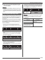
USER’S GUIDE
Please keep all information for future reference.
Safety Precautions
Before trying to use the keyboard, be sure to read the
separate “Safety Precautions”.
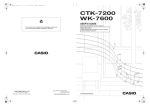
CTK7000/WK7500E1B
NOTICE
This equipment has been tested and found to comply with the limits for a Class B digital device, pursuant to Part 15 of the
FCC Rules. These limits are designed to provide reasonable protection against harmful interference in a residential
installation. This equipment generates, uses and can radiate radio frequency energy and, if not installed and used in
accordance with the instructions, may cause harmful interference to radio communications. However, there is no guarantee
that interference will not occur in a particular installation. If this equipment does cause harmful interference to radio or
television reception, which can be determined by turning the equipment off and on, the user is encouraged to try to correct
the interference by one or more of the following measures:
• Reorient or relocate the receiving antenna.
• Increase the separation between the equipment and receiver.
• Connect the equipment into an outlet on a circuit different from that to which the receiver is connected.
• Consult the dealer or an experienced radio/TV technician for help.
FCC WARNING
Changes or modifications not expressly approved by the party responsible for compliance could void the user’s authority to
operate the equipment.
Declaration of Conformity
Model Number: CTK-7000/WK-7500
Trade Name: CASIO COMPUTER CO., LTD.
Responsible party: CASIO AMERICA, INC.
Address: 570 MT. PLEASANT AVENUE, DOVER, NEW JERSEY 07801
Telephone number: 973-361-5400
This device complies with Part 15 of the FCC Rules, Operation is subject to the following two conditions:
(1) This device may not cause harmful interference, and (2) this device must accept any interference received, including
interference that may cause undesired operation.
Important!
Please note the following important information before using this product.
• Before using the optional AC Adaptor to power the unit, be sure to check the AC Adaptor for any damage first. Carefully check
the power cord for breakage, cuts, exposed wire and other serious damage. Never let children use an AC adaptor that is
seriously damaged.
• Never attempt to recharge batteries.
• Do not use rechargeable batteries.
• Never mix old batteries with new ones.
• Use recommended batteries or equivalent types.
• Always make sure that positive (+) and negative (–) poles are facing correctly as indicated near the battery compartment.
• Replace batteries as soon as possible after any sign they are getting weak.
• Do not short-circuit the battery terminals.
• The product is not intended for children under 3 years.
• Use only a CASIO AD-A12150LW adaptor.
• The AC adaptor is not a toy.
• Be sure to disconnect the AC adaptor before cleaning the product.
This mark applies in EU countries only.
Manufacturer:
CASIO COMPUTER CO.,LTD.
6-2, Hon-machi 1-chome, Shibuya-ku, Tokyo 151-8543, Japan
Responsible within the European Union:
CASIO EUROPE GmbH
Casio-Platz 1, 22848 Norderstedt, Germany
● Any reproduction of the contents of this manual, either in part or its entirety, is prohibited. Except for your own, personal
use, any other use of the contents of this manual without the consent of CASIO is prohibited under copyright laws.
● IN NO EVENT SHALL CASIO BE LIABLE FOR ANY DAMAGES WHATSOEVER (INCLUDING, WITHOUT LIMITATION,
DAMAGES FOR LOSS OF PROFITS, BUSINESS INTERRUPTION, LOSS OF INFORMATION) ARISING OUT OF THE
USE OF OR INABILITY TO USE THIS MANUAL OR PRODUCT, EVEN IF CASIO HAS BEEN ADVISED OF THE
POSSIBILITY OF SUCH DAMAGES.
● The contents of this manual are subject to change without notice.
● The actual appearance of the product may be different from that shown in the illustrations in this User’s Guide.
● Company and product names used in this manual may be registered trademarks of others.
E-1
Contents
General Guide ............................. E-4
Using the Mixer ......................... E-36
Reading the Display ............................................... E-6
Modes..................................................................... E-7
Menus..................................................................... E-7
, Precautions while “Please Wait” is displayed.... E-7
Saving Settings....................................................... E-8
Returning the Digital Keyboard to Its
Factory Default Settings ......................................... E-8
Mixer Overview..................................................... E-36
Mixer Operation .................................................... E-37
Mixer Parameter Settings ..................................... E-41
Getting Ready to Play ................ E-9
Preparing the Music Stand ..................................... E-9
Power Supply ......................................................... E-9
Connections .............................. E-11
Using the Tone Editor............... E-44
Tone Creation Overview....................................... E-44
Creating a User Tone ........................................... E-46
Tone Parameter Settings...................................... E-48
Using Drawbar Organ Tones ... E-50
Playing with a Drawbar Organ Tone..................... E-50
Editing Drawbar Organ Tones .............................. E-52
Connecting Headphones ...................................... E-11
Connecting a Pedal .............................................. E-11
Outputting Digital Keyboard Sound to
Audio Equipment or an Amplifier .......................... E-11
Outputting Input from an External Device or a
Microphone through the Digital Keyboard’s
Speakers .............................................................. E-12
Bundled and Optional Accessories....................... E-12
Music Presets............................ E-54
Selecting and Playing a Tone .... E-13
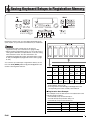
To save a setup to registration memory ............... E-67
To recall a setup from registration memory .......... E-67
To turn on Digital Keyboard power ....................... E-13
Listening to Demo Tunes...................................... E-14
Selecting a Tone................................................... E-14
Layering and Splitting Tones ................................ E-15
Raising and Lowering Keyboard Tuning
(Transpose) .......................................................... E-18
Using Octave Shift................................................ E-18
Using the Metronome ........................................... E-19
Using the Pitch Bend Wheel................................. E-20
Applying Vibrato to Notes ..................................... E-20
Selecting a Temperament and
Fine Tuning Its Scale............................................ E-21
Playing Arpeggio Phrases Automatically
(Arpeggiator)......................................................... E-23
Using Auto Accompaniment ... E-24
Playing an Auto Accompaniment.......................... E-24
Selecting a Chord Fingering Mode ....................... E-26
Modifying Auto Accompaniment Patterns............. E-27
Using One-Touch Presets .................................... E-27
Using Auto Harmonize.......................................... E-28
Applying Effects to a Sound.... E-29
Configuration of Effects ........................................ E-29
Selecting an Effect................................................ E-31
Creating a User DSP ............................................ E-33
E-2
Using Music Presets............................................. E-54
Creating a User Preset ......................................... E-58
Editing a Chord Progression................................. E-62
Saving Keyboard Setups to
Registration Memory ................ E-66
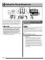
Using the Song Sequencer ...... E-68
Starting One-touch Recording (EASY REC) ........ E-68
What you can do with the song sequencer........... E-70
Recording Individual Tracks ................................. E-72
Re-recording Part of a Song
(Punch-in Recording)............................................ E-76
Using Panel Record to Rewrite Song
Header Settings.................................................... E-78
Playing a Recorded Song..................................... E-79
Editing a Song ...................................................... E-81
Editing a Track...................................................... E-85
Editing Events....................................................... E-87
Directly Inputting Note Events (Step Input) ........ E-100
Contents
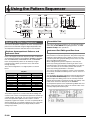
Using the Pattern
Sequencer ............................... E-102
About the Pattern Sequencer ............................. E-102
Creating a User Rhythm ..................................... E-103
Creating a User Rhythm by Combining
Exiting Rhythm Parts (Easy Edit) ....................... E-112
Editing Individual Events
(Event Editor)...................................................... E-113
Configuring Instrument Part Playback Settings
(Part Parameters) ............................................... E-116
Instrument Part Operations ................................ E-118
Accompaniment Pattern and
Rhythm Operations............................................. E-120
Reference................................. E-148
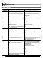
Error Messages .................................................. E-148
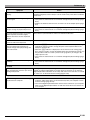
Troubleshooting.................................................. E-150
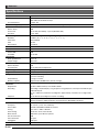
Specifications ..................................................... E-152
Operating Precautions........................................ E-154
DSP Effect List ................................................... E-155
Fingering Guide .................................................. E-160
Supported Input Characters ............................... E-160
Chord Example List ............................................ E-161
Assigning a MIDI Channel to Each Part ............. E-162
Parameter List .................................................... E-163
MIDI Implementation Chart
Recording and Playing
Audio ....................................... E-121
Audio Recording and Playback Functions.......... E-121
Audio Recording and Playback Precautions ...... E-121
Performing Audio Recording .............................. E-122
Playing Back Audio............................................. E-126
Using the Function Menu....... E-130
Using the Function Menu.................................... E-130
Function Menu Settings...................................... E-131
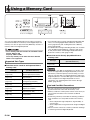
Using a Memory Card............. E-136
Loading and Removing a Memory Card............. E-137
Entering the Card Mode ..................................... E-137
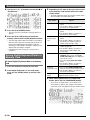
Formatting a Memory Card................................. E-137
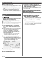
Saving Digital Keyboard Data to a
Memory Card...................................................... E-138
Loading Data from a Memory Card .................... E-140
To delete a file from a memory card................... E-141
To rename a file on a memory card.................... E-141
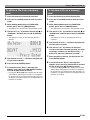
Playing a Music File from a Memory Card.......... E-142
Connecting to a Computer .... E-145
Minimum Computer System Requirements........ E-145
Storing and Loading Digital Keyboard
Memory Data ...................................................... E-146
Using Rhythm (Auto Accompaniment)
Data from another Model.................................... E-146
Importing Data from Various Storage Media ...... E-147
E-3
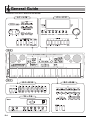
General Guide
• Illustrations in this User’s Guide show the WK-7500.
L-1 - L-18
C-1 - C-17
Dial
S-2
S-1
D-1 - D-12
T-1 - T-9
Back
E-4
R-1 - R-20
General Guide
• In this manual, the term “Digital Keyboard” refers to the CTK-7000/WK-7500.
• This manual uses the numbers and names below to refer to buttons and controllers.
• The following explains the meanings of the # and $ symbols that appear on the product console and with the key names below.
# : Indicates a function that is enabled by holding down the R-13 (FUNCTION) button when pressing a button. For example, SONG SEQUENCER, #
EDIT means that the EDIT function is enabled by depressing the R-13 (FUNCTION) button.
$ : Indicates a function that is enabled by holding down the button for some time. For example, METRONOME, BEAT $ means that the BEAT function is
enabled by holding down the button for some time.
L-1
L-2
L-3
POWER button . . . . . . . . . . . . . . . . . . . . . . . . . . . . . . . . . . . . ☞13
MAIN VOLUME knob . . . . . . . . . . . . . . . . . . . . . . . . . . . . . . . ☞13
MIC VOLUME knob . . . . . . . . . . . . . . . . . . . . . . . . . . . . . . . . ☞12
RHYTHM buttons
L-4
L-5
L-6
L-7
L-8
L-9
[A] POPS/ROCK/DANCE button . . . . . . . . . . . . . . . . ☞14, 24
[B] JAZZ/EUROPEAN button . . . . . . . . . . . . . . . . . . . . . ☞24
[C] LATIN button . . . . . . . . . . . . . . . . . . . . . . . . . . . . . . . ☞24
[D] WORLD/VARIOUS,
MUSIC PRESET button . . . . . . . . . . . . . . . . . . . . . . . ☞24, 54
[E] PIANO RHYTHMS,
ONE TOUCH PRESET button . . . . . . . . . . . . . . . ☞24, 27, 54
[F] USER RHYTHMS button . . . . . . . . . . . . . . . . . . . ☞24, 27
L-10 METRONOME, $BEAT button . . . . . . . . . . . . . . . . . . . . . . ☞19
L-11 TEMPO w button . . . . . . . . . . . . . . . . . . . . . . . . . . . . . . . . . ☞19
L-12 TEMPO q, #TAP button. . . . . . . . . . . . . . . . . . . . . . . . . ☞19
RHYTHM/SONG CONTROLLER buttons
INTRO, REPEAT button . . . . . . . . . . . . . . . . . . . ☞27, 80, 142
NORMAL/FILL-IN, sREW button . . . . . . . ☞14, 27, 79, 142
VARIATION/FILL-IN, dFF button . . . . . . . ☞14, 27, 79, 142
SYNCHRO/ENDING, PAUSE button . . . . . . ☞24, 27, 79, 142
START/STOP, PLAY/STOP,
DEMO button . . . . . . . . . . . . . . . . . . . . . . . . ☞14, 24, 79, 142
L-18 ACCOMP ON/OFF, $CHORDS,
PART SELECT, DEMO button . . . . . . . . . . . ☞14, 24, 26, 143
L-13
L-14
L-15
L-16
L-17
C-1
C-2
C-3
C-4
C-5
C-6
C-7
C-8
C-9
Display . . . . . . . . . . . . . . . . . . . . . . . . . . . . . . . . . . . . . . . . . . . ☞6
AUDIO PLAY button . . . . . . . . . . . . . . . . . . . . . . . . . . . . . . ☞126
AUDIO RECORD button . . . . . . . . . . . . . . . . . . . . . . . . . . . ☞123
PATTERN SEQUENCER, #EDIT button . . . . . . . . . . . . ☞102
SONG SEQUENCER, #EDIT button . . . . . . . . . . . ☞7, 72, 81
RECORD button . . . . . . . . . . . . . . . . . . . . . . . . . . . . . ☞68, 72, 73
MIXER, #EFFECT button . . . . . . . . . . . . . . . . . . . . . . ☞31, 37
TONE EDITOR, #SCALE button . . . . . . . . . . . . . . . . ☞21, 46
CARD, #LOAD/SAVE button . . . . . . . . . . . ☞7, 137, 138, 140
Dial . . . . . . . . . . . . . . . . . . . . . . . . . . . . . . . . . . . . . . . . ☞6, 14, 24
REGISTRATION buttons
C-10
C-11
C-12
C-13
C-14
C-15
C-16
C-17
BANK, DELETE button . . . . . . . . . . . . . . . . . ☞63, 66, 92, 99
1, INSERT button . . . . . . . . . . . . . . . . . . . . . ☞63, 66, 94, 100
2, COPY button. . . . . . . . . . . . . . . . . . . . . . . . . . . . . . ☞66, 94
3, QUANTIZE button . . . . . . . . . . . . . . . . . . . . . . . . . ☞66, 95
4, STEP button . . . . . . . . . . . . . . . . . . . . . . . . . . ☞64, 66, 100
5 button. . . . . . . . . . . . . . . . . . . . . . . . . . . . . . . . . . . . . . . ☞66
6 button. . . . . . . . . . . . . . . . . . . . . . . . . . . . . . . . . . . . . . . ☞66
STORE, #MENU button . . . . . . . . . . . . . . . . . . . . . ☞7, 66
TONE buttons
R-1
R-2
R-3
R-4
R-5
R-6
R-7
R-8
R-9
R-10
R-11
R-12
[A] PIANO, 5 button . . . . . . . . . . . . . . . . . . . . . . . ☞14, 63, 94
[B] E.PIANO, 1 button . . . . . . . . . . . . . . . . . . . . . ☞14, 63, 94
[C] ORGAN, 2 button . . . . . . . . . . . . . . . . . . . ☞14, 63, 94, 95
[D] GUITAR/BASS, • button . . . . . . . . . . . . . . . . . ☞14, 63, 94
[E] STRINGS, REST button . . . . . . . . . . . . . . . . . . . ☞14, 100
[F] BRASS button . . . . . . . . . . . . . . . . . . . . . . ☞14, 63, 94, 95
[G] REED/PIPE, 6 button. . . . . . . . . . . . . . . . ☞14, 63, 94, 95
[H] SYNTH, 7 button . . . . . . . . . . . . . . . . . . . ☞14, 63, 94, 95
[I] OTHERS, 8 button. . . . . . . . . . . . . . . . . . . . . . ☞14, 94, 95
[J] GM/DRUMS, , button . . . . . . . . . . . . . . . . . ☞14, 94, 95
[K] USER TONES, . button . . . . . . . . . . . . . . . ☞14, 46
[L] DRAWBAR ORGAN,
$MANUAL button . . . . . . . . . . . . . . . . . . . . . . . . . . . . . ☞50
R-13 FUNCTION button . . . . . . . . . . . . . . . . . . . . . . . . . . . . . . . . ☞130
R-14 NO/y/–, YES/t/+,
#TRANSPOSE buttons . . . . . . . . . . . . . . . . . . . ☞6, 14, 18, 24
R-15 EXIT button
R-16 ENTER button
R-17 u, t, y, i buttons . . . . . . . . . . . . . . . . . . . . . . . . . . . . . . . ☞7
R-18 AUTO HARMONIZE/ARPEGGIATOR,
$TYPE button . . . . . . . . . . . . . . . . . . . . . . . . . . . . . . . . ☞23, 28
R-19 SPLIT button. . . . . . . . . . . . . . . . . . . . . . . . . . . . . . . . . . . . . . ☞16
R-20 LAYER, $OCTAVE button . . . . . . . . . . . . . . . . . . . . . . ☞16, 18
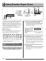
D-1 ROTARY SLOW/FAST, PART/COMMON button . . . . . . . . . ☞51
D-2 PERCUSSION SECOND, GROUP A/B button . . . . . . . . . . . ☞51
D-3 PERCUSSION THIRD, 1-8/9-16 button . . . . . . . . . . . . . . . . . ☞51
D-4 16', 1/9/EXT slider. . . . . . . . . . . . . . . . . . . . . . . . . . . . . . . . . . ☞51
D-5 5 1/3' , 2/10/DSP slider . . . . . . . . . . . . . . . . . . . . . . . . . . . . . . ☞51
D-6 8', 3/11 slider. . . . . . . . . . . . . . . . . . . . . . . . . . . . . . . . . . . . . . ☞51
D-7 4', 4/12 slider. . . . . . . . . . . . . . . . . . . . . . . . . . . . . . . . . . . . . . ☞51
D-8 2 2/3', 5/13 slider . . . . . . . . . . . . . . . . . . . . . . . . . . . . . . . . . . . ☞51
D-9 2', 6/14 slider. . . . . . . . . . . . . . . . . . . . . . . . . . . . . . . . . . . . . . ☞51
D-10 1 3/5', 7/15 slider . . . . . . . . . . . . . . . . . . . . . . . . . . . . . . . . . . . ☞51
D-11 1 1/3', 8/16 slider . . . . . . . . . . . . . . . . . . . . . . . . . . . . . . . . . . . ☞51
D-12 1', MASTER slider . . . . . . . . . . . . . . . . . . . . . . . . . . . . . . . . . ☞51
S-1 PITCH BEND wheel . . . . . . . . . . . . . . . . . . . . . . . . . . . . . . . . ☞20
S-2 MODULATION button. . . . . . . . . . . . . . . . . . . . . . . . . . . . . . . ☞20
T-1 SD CARD SLOT . . . . . . . . . . . . . . . . . . . . . . . . . . . . . . . . . . ☞136
T-2 USB jack . . . . . . . . . . . . . . . . . . . . . . . . . . . . . . . . . . . . . . . . ☞145
T-3 SUSTAIN/ASSIGNABLE JACK. . . . . . . . . . . . . . . . . . . . . . . ☞11
T-4 PHONES jack . . . . . . . . . . . . . . . . . . . . . . . . . . . . . . . . . . . . . ☞11
T-5 INST IN jack . . . . . . . . . . . . . . . . . . . . . . . . . . . . . . . . . . . . . . ☞12
T-6 AUDIO IN jack . . . . . . . . . . . . . . . . . . . . . . . . . . . . . . . . . . . . ☞12
T-7 DC 12V jack . . . . . . . . . . . . . . . . . . . . . . . . . . . . . . . . . . . . . . . ☞9
T-8 MIC IN jack . . . . . . . . . . . . . . . . . . . . . . . . . . . . . . . . . . . . . . . ☞12
T-9 LINE OUT R, L/MONO jacks . . . . . . . . . . . . . . . . . . . . . . . . . ☞11
E-5
General Guide
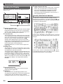
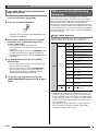
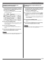
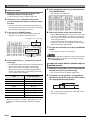
6 Tempo, measure, beat area
Reading the Display
This section explains the contents of the Digital Keyboard’s
display screen.
1
2
Tempo is shown as the current setting value, as beats per
minute. Auto Accompaniment, the metronome (page
E-19), and other playback is performed at the tempo
shown here. The MEASURE and BEAT values are
counted up as Auto Accompaniment, the metronome, or
other playback progresses.
Currently Selected Item Indication
The item that is currently selected on a display screen is
indicated by thick brackets (%) and by a large dot (0). The
currently selected item is the one that is affected by the R-14
(–, +) buttons or dial operations.
4 5
6
3
1 Detailed information area
This area displays a variety of information while the Digital
Keyboard is being used. Use this area to confirm proper
operation when changing values, when selecting a menu
item, and when performing other operations.
2 Level meter area
This level meter shows the volume level of the notes that
are sounded when you play something on the keyboard or
when Auto Accompaniment is played. There are a total of
32 parts, 16 each in Group A and Group B. The L
indicator will be displayed in the lower left corner while
Group A parts are being indicated by the level meter, while
the M indicator will be displayed in the lower left corner
while Group B parts are being indicated.
For details about parts, see “How Parts are Organized”
(page E-36).
3 Indicator areas
The indicator area shows such information as the current
mode (page E-7), the status of settings, the status of Auto
Accompaniment, and other information.
There are two types of indicators: text type indicators such
as :, and pointer (K) type indicators. In the case of
pointer type indicators, a setting or status is indicated by
the location of the K next to fixed text along the sides of the
display. For example, the location of the pointer (K) on the
right side of the display in the sample below indicates
REVERB.
4 Registration bank area
This area shows the number of the currently selected
registration bank (page E-66).
5 Chord area
This area shows the chord being played when Auto
Accompaniment (page E-24) or music preset (page E-54)
is being used. It also can display fraction chords by
showing the chord root (C, G, etc.) and type (m, 7th, etc.).
E-6
On this screen, “RHYTHM” is selected because it is enclosed
by thick brackets. This indicates that the rhythm setting can be
changed.
On this screen, “Touch” is selected because the 0 is next to
it. This indicates that the value to the right of “Touch”, which is
enclosed in thick brackets, can be changed.
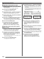
General Guide
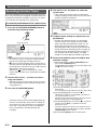
Modes
Menus
Your Digital Keyboard has three modes: a rhythm mode, a
card mode, and a song sequencer mode. The currently
selected mode is shown as an indicator on the display.
Card mode
C-9 (CARD) or
R-15 (EXIT) button
You can use the same operations to display mode and
function specific menus. To display a menu, hold down the
R-13 (FUNCTION) button as you press the C-17 (MENU)
button. For example, the “Performance” menu shown below
will appear if you perform the above operation while in the
rhythm mode. This menu provides instant access to
performance functions.
C-9 (CARD) button
Rhythm mode
C-5 (SONG
SEQUENCER) button
C-5 (SONG SEQUENCER) or
R-15 (EXIT) button
Song sequencer mode
• Rhythm mode (: indicator displayed)
Under its initial factory default settings, the Digital Keyboard
enters the rhythm mode whenever it is turned on. The
rhythm mode is the base mode, and it is the mode you
should enter when you want to play on the keyboard or use
Auto Accompaniment.
• Card mode (; indicator displayed)
Enter the card mode when you want to perform memory
card operations. See “Using a Memory Card” (page E-136)
for more information.
– In the rhythm mode, pressing the C-9 (CARD) button will
enter the card mode.
– In the card mode, pressing the C-9 (CARD) button or the
R-15 (EXIT) button will return to the rhythm mode.
• Song sequencer mode (< indicator displayed)
Enter the sequencer mode when you want to record
performances using the keyboard and Auto
Accompaniment, or to play back song data. For details, see
“Using the Song Sequencer” (page E-68).
– In the rhythm mode, pressing the C-5 (SONG
SEQUENCER) button will enter the song sequencer
mode.
– In the song sequencer mode, pressing the C-5 (SONG
SEQUENCER) button or the R-15 (EXIT) button will
return to the rhythm mode.
• The currently selected item is the one with the 0 next to it.
You can use the R-17 (t, y) buttons to move the 0 up
and down. You also can use the R-17 (u, i) buttons to
scroll between menu pages.
• To exit a displayed menu, press the R-15 (EXIT) button.
You may need to press the R-15 (EXIT) button more than
once in some cases.
• The menu items and operations for specific modes and
functions are described in each section of this user’s guide.
, Precautions while “Please
Wait” is displayed
Never try to perform any operation, or insert or remove a
memory card while the message “Please Wait” is on the
display. Wait until the message disappears.
• “Please Wait” indicates that the Digital Keyboard is
performing a data save operation. Turning off the Digital
Keyboard or removing the memory card can cause Digital
Keyboard data to be deleted or become corrupted. It also
can cause the Digital Keyboard to fail to turn on when the
L-1 (POWER) button is pressed.
• If this happens, refer to “Troubleshooting” (page E-150).
• After entering any mode besides the rhythm mode and
performing the operations you want, be sure to return
to the rhythm mode.
• Unless otherwise specifically noted, all of the
operations described in this user’s guide are
performed in the rhythm mode.
E-7
General Guide
Saving Settings
Your Digital Keyboard is equipped with a song sequencer and
other features that you can use to store data you create. This
stored data is retained even when the Digital Keyboard is
turned off.*
However, the tone, rhythm, and other settings you configure
on the Digital Keyboard’s console normally are returned to
their initial power on defaults whenever you turn off power.
You can configure the Digital Keyboard so it remembers its
latest setup or to apply a predetermined default setup each
time you turn it on. For details, see “AutoResume (Auto
Resume)” (page E-134) and “Default (Default Settings)” (page
E-134).
* The following data and settings are always retained even
when power is turned off.
– Registration setup data (page E-66)
– Song sequencer data (page E-68)
– User rhythm data (page E-103)
– User preset data (page E-58)
– User tone data (page E-44)
– User drawbar organ tone data (page E-50)
– User DSP data (page E-33)
– LCD Contrast setting (page E-133)
– Auto Resume setting (page E-134)
Returning the Digital Keyboard to
Its Factory Default Settings
You can delete all data in keyboard memory and return all
keyboard parameters to their initial factory default settings.
For details, see “To initialize all data and settings (or
parameter settings only)” (page E-135).
E-8
B
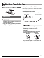
Getting Ready to Play
Preparing the Music Stand
Music stand
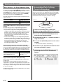
Using a Household Power Outlet
Make sure that you use only the AC adaptor (JEITA Standard,
with unified polarity plug) specified for this product. Use of a
different type of AC adaptor can cause malfunction.
Specified AC Adaptor: AD-A12150LW
Use the supplied power cord to connect the AC adaptor as
shown in the illustration below.
T-7 (DC 12V) jack
Household power outlet
Power Supply
Prepare a household power outlet or batteries.
Power cord
• Be sure to comply with the separate “Safety
Precautions”. Incorrect use of this product creates the
risk of electric shock and fire.
• Always make sure that the product is turned off before
plugging in or unplugging the AC adaptor, or before
loading or removing batteries.
AC adaptor
• The shape of the power cord plug and household
power outlet receptacle differ according to country and
geographical area. The illustration shows just one
example of the shapes that are available.
• The AC adaptor will become warm to the touch after
very long use. This is normal and does not indicate
malfunction.
• To prevent breaking of the wire, take care to avoid
putting any type of load on the power cord.
No bending!
No winding!
• Never insert metal, pencils, or any other objects into
the product’s DC 12V jack. Doing so creates the risk of
accident.
E-9
Getting Ready to Play
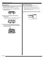
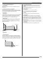
■ Low Battery Indication
Using Batteries
You can use six D-size batteries for power.
• Use alkaline or zinc-carbon batteries.
Never use oxyride or any other nickel based batteries.
1. Open the battery cover on the bottom of the
Digital Keyboard.
The following shows the approximate battery life.
4 hours* on alkaline batteries
* The above values are standard battery life at normal
temperature, with the volume at medium setting.
Temperature extremes or playing at very loud volume
settings can shorten battery life.
The indicators shown below start to flash to let you know
when battery power is low. Replace the batteries with new
ones.
2. Load six D-size batteries into the battery
compartment.
• Make sure the positive + and negative - ends of the
batteries are facing as shown in the illustration.
Low battery indication (flashing)
3. Insert the tabs of the battery cover into the
holes on the side of the battery compartment,
and close the cover.
Tabs
E-10
Connections
Connecting Headphones
Using headphones cuts off output from the built-in speakers,
which means you can practice playing even late at night
without disturbing others.
• Be sure to turn down the volume level before connecting
headphones.
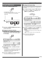
Outputting Digital Keyboard
Sound to Audio Equipment or an
Amplifier
You can connect audio equipment or a music amplifier to the
Digital Keyboard and then play through external speakers for
more powerful volume and better sound quality.
T-4 (PHONES) jack
• Whenever connecting a device to the Digital Keyboard,
first use the L-2 (MAIN VOLUME) knob to set the
volume to a low level. After connecting, you can adjust
the volume to the level you want.
• Whenever you connect any device to the Digital
Keyboard, be sure to read the user documentation that
comes with the device.
• Headphones do not come with the Digital Keyboard.
• Use commercially available headphones.
Pin plug
Audio amplifier AUX IN jack, etc.
RIGHT (Red)
LEFT (White)
• Do not listen to very high volume output over
headphones for long periods. Doing so creates the risk
of hearing damage.
• If you are using headphones that require an adaptor
plug, make sure you do not leave the adaptor plugged
in when removing the headphones.
Connecting a Pedal
Connecting an optionally available pedal let’s you perform
pedal operations that add more versatility to your keyboard
play. For information about the types of effects that can be
applied by pressing the pedal, see “Ped.Assign (Pedal
Assign)” (page E-131).
T-3 (SUSTAIN/ASSIGNABLE JACK)
Guitar amplifier
Keyboard amplifier, etc.
INPUT 1
INPUT 2
Standard plug
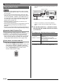
Outputting Keyboard Notes to Audio
Equipment 1
Use commercially available connecting cords to connect the
external audio equipment to the Digital Keyboard’s T-9 (LINE
OUT) jacks as shown in Figure 1. LINE OUT R jack output is
right channel sound, while LINE OUT L/MONO jack output is
left channel sound. It is up to you to purchase connecting
cords like the ones shown in the illustration for connection of
audio equipment. Normally in this configuration you must set
the audio equipment’s input selector to the setting that
specifies the terminal (such as AUX IN) to which the Digital
Keyboard is connected. Use the L-2 (MAIN VOLUME) knob
to adjust the volume level.
Outputting Keyboard Notes to a Musical
Instrument Amplifier 2
Use a commercially available connecting cord to connect the
amplifier to either of the Digital Keyboard’s T-9 (LINE OUT)
jacks as shown in Figure 2. LINE OUT R jack output is right
channel sound, while LINE OUT L/MONO jack output is left
channel sound. Connecting to the LINE OUT L/ MONO jack
only outputs a mixture of both channels. It is up to you to
purchase a connecting cord like the one shown in the
illustration for connection of the amplifier. Use the L-2 (MAIN
VOLUME) knob to adjust the volume level.
E-11
Connections
Outputting Input from an External
Device or a Microphone through
the Digital Keyboard’s Speakers
You can use the Digital Keyboard’s speakers to output sound
from a CD player, another digital keyboard, or other external
device, or from a microphone.
• Whenever connecting something to the Digital
Keyboard, first use the L-2 (MAIN VOLUME) knob to set
the volume to a low level. After connecting, you can
adjust the volume to the level you want.
• Whenever you connect any device to the Digital
Keyboard, be sure to read the user documentation that
comes with the device.
• Digital Keyboard built-in effects (reverb, chorus, DSP) are
not applied to input from the T-6 (AUDIO IN) jack. Input is
output directly, and is affected by the Digital Keyboard’s
build-in amplifier and L-2 (MAIN VOLUME) knob.
• Digital Keyboard built-in effects (reverb, chorus, DSP) are
applied to input from the T-5 (INST IN) and T-8 (MIC IN)
jacks. You also can use the Mixer to adjust how effects are
applied, the speaker stereo pan position, and other
parameters.
For details, see “Applying Effects to a Sound” (page E-29)
and “Using the Mixer” (page E-36).
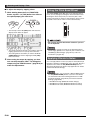
Output of External Device Input that is
Affected by the Digital Keyboard’s Effects
Use a commercially available connecting cord to connect the
external device to the Digital Keyboard’s T-5 (INST IN) jack.
The connecting cord should have a standard plug (monaural)
on one end and a plug that is compatible with the external
device you are connecting to on the other end. Adjust volume
using the Digital Keyboard’s L-2 (MAIN VOLUME) knob.
CD player,
Portable audio player, etc.
Standard plug (monaural)
Outputting Sound with a Microphone
You can connect a dynamic microphone (only) to the Digital
Keyboard for output thorough the Digital Keyboard’s
speakers.
T-8 (MIC IN) jack
• You can adjust the volume level of microphone input with
the L-3 (MIC VOLUME) knob. Microphone volume control
is independent of overall keyboard volume.
Output of External Device Input that is Not
Affected by the Digital Keyboard’s Effects
Use a commercially available connecting cord to connect the
external device to the Digital Keyboard’s T-6 (AUDIO IN) jack.
The connecting cord should have a stereo mini plug on one
end and a plug that is compatible with the external device you
are connecting to on the other end. Adjust volume using the
Digital Keyboard’s L-2 (MAIN VOLUME) knob.
CD player,
Portable audio player, etc.
Stereo mini plug
• Before connecting a microphone, make sure that the
Digital Keyboard and microphone are turned off.
• Before connecting a microphone, set both the L-2
(MAIN VOLUME) and L-3 (MIC VOLUME) knobs to low
levels. Adjust volume settings to appropriate levels
after connecting the microphone.
Bundled and Optional
Accessories
Use of unauthorized accessories creates the risk of fire,
electric shock, and personal injury.
• You can get information about accessories that are sold
separately for this product from the CASIO catalog
available from your retailer, and from the CASIO website at
the following URL.
http://world.casio.com/
E-12
Selecting and Playing a Tone
L-1
L-4
R-1
R-1- R-12
R-12
L-2
R-14
L-17
L-14
L-18
L-15
R-19
R-20
To turn on Digital Keyboard power
1. Rotate the L-2 (MAIN VOLUME) knob towards
MIN to set the volume to a low level.
2. Referring to “Connections” (page E-11),
connect headphones, amplifier, or other device.
3. Use the L-1 (POWER) button to turn on power.
• The Digital Keyboard display screen will appear as
shown below, which indicates that it is ready to play
with a piano tone (using initial power on default
settings).
• Under its initial configuration, the Digital Keyboard will
return to its default settings whenever you turn it off.
You can change the initial configuration to have the
Digital Keyboard remember its latest setup or to apply
a predetermined setup each time you turn it on. For
details, see “AutoResume (Auto Resume)” (page
E-134) and “Default (Default Settings)” (page E-134).
• The message “Please Wait” will remain on the display
while a data save operation is in progress. Do not
perform any other operation while it is displayed.
Turning off the Digital Keyboard or removing the
memory card can cause Digital Keyboard data to be
deleted or become corrupted. It also can cause the
Digital Keyboard to fail to turn on when the L-1
(POWER) button is pressed. If this happens, refer to
“Troubleshooting” (page E-150).
Auto Power Off
• To turn off the Digital Keyboard, press the L-1
(POWER) button again.
This Digital Keyboard is designed to turn off automatically to
avoid wasting power after no operation is performed for a
preset amount of time. The Auto Power Off trigger time is six
minutes under battery power and four hours under AC
adaptor power.
• Auto Power Off is enabled while “on” is selected for
“AutoPower (Auto Power Off)” (page E-134). The initial
default setting is “on”. To disable Auto Power Off, select
“oFF” for “AutoPower” (Auto Power Off).
• You also can use the procedure below to temporarily
suspend Auto Power Off while it is enabled.
E-13
Selecting and Playing a Tone
■ To disable Auto Power Off
1. While the Digital Keyboard is turned on, press
the L-1 (POWER) button to turn it off.
2. While holding down the L-4 ([A] POPS/ROCK/
DANCE) button, press the L-1 (POWER) button
to turn on the Digital Keyboard.
Selecting a Tone
The tones of this Digital Keyboard are divided among groups,
each of which corresponds to one of the 12 TONE buttons.
You can specify a tone by its group and its tone number.
Use the following procedure to select a single tone that is
applied across the entire keyboard.
To select a tone
1. Refer to the separate “Appendix” to look up the
group and the number of the tone you want to
select.
• Auto Power Off will be disabled at this time.
2. Check to make sure that the @ and A
indicators are not on the display.
• Turning off the keyboard after performing the above steps
will re-enable Auto Power Off.
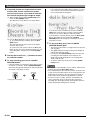
Listening to Demo Tunes
• If they are displayed, press the R-19 (SPLIT) button
and/or R-20 (LAYER) button to clear both indicators
from the display.
3. Use buttons R-1 ([A] PIANO) through R-11 ([K]
USER TONES) to select a tone group.
1. While holding down the L-18 (ACCOMP ON/
OFF) button, press the L-17 (PLAY/STOP)
button.
• This starts demo tune play.
• The Digital Keyboard has a total of five demo tunes.
You also can use the R-14 (–, +) buttons to select a
demo tune.
• Pressing the L-15 (dFF) button performs fast forward
play of the demo tune, while the L-14 (sREW) button
performs fast backward play. Holding down the L-14
(sREW) button until playback reaches the beginning
of the current song will stop playback there. Normal
playback will resume when you release the L-14
(sREW) button. Holding down the L-15 (dFF)
button continues fast forward playback, even after the
end of a song is reached.
• You can play along on the keyboard with demo tune
play. Note, however, that you cannot change the tone
assigned to the keyboard. Only the key operations
described above are supported during demo tune
playback.
2. To stop demo tune playback, press the L-17
(PLAY/STOP) button.
E-14
• The R-11 ([K] USER TONES) button selects the user
tone group. For details, see “Using the Tone Editor”
(page E-44).
• The R-12 ([L] DRAWBAR ORGAN) button selects the
drawbar organ tone group. See “Using Drawbar Organ
Tones” (page E-50) for more information.
4. Use the dial to scroll through the tone numbers
until the one you want is displayed.
Example: Group [C], Number 004
Number
Tone name
Group
Selecting and Playing a Tone
5. Now you can play on the keyboard using the
tone you selected.
• You also can use the R-14 (–, +) buttons to select a tone.
Holding down either button will scroll through tone numbers
at high speed. Pressing both of the R-14 (–, +) buttons at
the same time will select tone 001 in the currently selected
group.
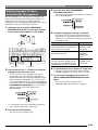
• Three tones, two layered tones for the right range and
one tone for the left range of the keyboard (page E-17)
This configuration uses the UPPER 1 part, UPPER 2 part,
and LOWER part (Layer: On, Split: On).
LOWER
UPPER 1
UPPER 2
Layering and Splitting Tones
You can configure the keyboard to play two different tones at
the same time (Layer) or to play different tones in the left and
right ranges (Split). You can even use Layer and Split in
combination with each other and play three different tones at
the same time.
The UPPER 1 part is used alone when playing an individual
tone on the keyboard. When layering two tones, the UPPER 1
part and UPPER 2 parts are used. When splitting the
keyboard between two tones, the low range of the keyboard
plays the LOWER part.
• One tone across the entire keyboard (page E-14)
This configuration uses the UPPER 1 part only (Layer: Off,
Split: Off).
• You can configure the settings described below to adjust
each part when using multiple tones in layer and split
configurations.
To adjust this setting for
each part:
Go here for more
information:
Octave shift
Using Octave Shift
(page E-18)
Volume balance
Using the Mixer (page E-36)
Stereo position, effect
(reverb, chorus) levels, and
other detailed settings
UPPER 1
• Two layered tones across the entire keyboard (page
E-16)
This configuration uses the UPPER 1 part and UPPER 2
part (Layer: On, Split: Off).
UPPER 1
UPPER 2
• Two tones, one for the left range and one for the right
range of the keyboard (page E-17)
This configuration uses the UPPER 1 part and LOWER part
(Layer: Off, Split: On).
LOWER
UPPER 1
E-15
Selecting and Playing a Tone
R-14
R-19
R-20
To layer two tones
1. Refer to the separate “Appendix” to look up the
group(s) and numbers of the two tones (UPPER
1 part tone and UPPER 2 part tone) you want to
use.
2. Check to make sure that the @ and A
To split the keyboard between two tones
1. Refer to the separate “Appendix” to look up the
group(s) and numbers of the tones (UPPER 1
part tone and LOWER part tone) you want to
use.
2. Check to make sure that the @ and A
indicators are not on the display.
indicators are not on the display.
• If they are displayed, press the R-19 (SPLIT) button
and/or R-20 (LAYER) button to clear both indicators
from the display. When neither indicator is displayed,
the tone you select will become the UPPER 1 part tone.
• If they are displayed, press the R-19 (SPLIT) button
and/or R-20 (LAYER) button to clear both indicators
from the display. When neither indicator is displayed,
the tone you select will become the UPPER 1 part tone.
3. Use the TONE buttons and dial to select the
UPPER 1 part tone.
4. Press the R-20 (LAYER) button.
3. Use the TONE buttons and dial to select the
UPPER 1 part tone.
4. Press the R-19 (SPLIT) button.
• This causes the A indicator to appear on the
display. This indicates that the tone you select will
become the UPPER 2 part tone.
• This causes the @ indicator to appear on the
display. This indicates that the tone you select will
become the LOWER part tone.
5. Use the TONE buttons and dial to select the
5. Use the TONE buttons and dial to select the
UPPER 2 part tone.
6. Play something on the keyboard to check how
the tones sound layered together.
7. To cancel tone layering, press the R-20 (LAYER)
button again so the A indicator disappears
from the display.
LOWER part tone.
6. Play something on the left and right sides of the
keyboard to confirm that the tones are assigned
properly.
• You also can specify the keyboard split point, which is
the location where the keyboard splits between the left
range and right range. For details, see “To specify the
keyboard split point” (page E-17).
7. To cancel keyboard split, press the R-19 (SPLIT)
button so the @ indicator disappears from
the display.
E-16
Selecting and Playing a Tone
To specify the keyboard split point
To use layer and split together
1. While holding down the R-19 (SPLIT) button,
press the keyboard key that you want to be the
leftmost key in the right side (UPPER 1 part)
range.
LOWER part
UPPER 1 part
1. Perform steps 1 through 6 of the procedure
under “To layer two tones” (page E-16).
2. Refer to the separate “Appendix” to look up the
group and the number of the tone you want to
assign to for the LOWER part.
3. Press the R-19 (SPLIT) button.
• This causes the @ indicator to appear on the
display. This indicates that the tone you select will
become the LOWER part tone.
Key you press
4. Use the TONE buttons and dial to select the
LOWER part tone.
Split point
• The name of the key you press will appear on the
display as the new split point key name.
• You also can use the R-14 (–, +) buttons to change the
displayed split point key name.
2. When you are finished, release the R-19 (SPLIT)
button.
• The initial default split point is at key F#3.
• During Auto Accompaniment play (page E-24), the
keyboard to the left of the split point becomes the chord
keyboard.
5. Play something on the left and right sides of the
keyboard to confirm that the tones are assigned
properly.
• The right keyboard area plays the UPPER 1 and
UPPER 2 tones in a layered configuration, while the left
keyboard area plays the LOWER tone.
6. To cancel keyboard split, press the R-19 (SPLIT)
button so the @ indicator disappears from
the display.
7. To cancel tone layering, press the R-20 (LAYER)
button again so the A indicator disappears
from the display.
E-17
Selecting and Playing a Tone
Raising and Lowering Keyboard
Tuning (Transpose)
The transpose feature lets you raise or lower the overall
tuning of the keyboard in semitone steps. You can use this
feature to adjust keyboard tuning to a key that better matches
a vocalist, another musical instrument, etc.
1. While holding down the R-13 (FUNCTION)
button, press one of the R-14 (–, +) buttons.
Using Octave Shift
You can use octave shift to individually change the octave of
the UPPER 1, UPPER 2, and LOWER parts. You can use
octave shift to raise or lower the octave of a song, to assign
different octaves to the left side and right side keyboards while
the keyboard is split, or to play two notes in different octaves
while the keyboard is layered.
1. Hold down the R-20 (OCTAVE) button until the
octave shift screen shown below appears on
the display.
Octave shift amount (Octave unit)
Part name
• This displays the transpose screen shown below.
• This indicates you can change the UPPER 1 part
octave.
2. Use the dial or R-14 (–, +) buttons to specify the
2. While holding down the R-13 (FUNCTION)
button, use the dial or the R-14 (–, +) buttons to
change the setting value.
• You can change the tuning of the keyboard within the
range of –12 to 00 to +12.
3. Press the R-13 (FUNCTION) button.
• This exits the transpose screen.
• Setting a transposed value other than 00 will cause the
B indicator to appear on the display.
• The current transpose setting is applied to the notes of all
parts (UPPER 1, UPPER 2, LOWER, Auto Accompaniment,
etc.) played on the keyboard. The MIDI out note number
when a keyboard key is pressed is also shifted in
accordance with the transpose setting.
octave shift amount.
• You can shift the octave within the range of –2 to 0 to
+2.
3. If you want to change the octave of the
UPPER 2 part, press the R-20 (OCTAVE) button.
• This will cause “UPPER 2” to appear on the display,
indicating that you can change the UPPER 2 part
octave. Perform the same operation as in step 2 to
specify the octave shift amount.
4. If you want to change the octave of the LOWER
part, press the R-20 (OCTAVE) button.
• This will cause “LOWER” to appear on the display,
indicating that you can change the LOWER part octave.
Perform the same operation as in step 2 to specify the
octave shift amount.
5. Press the R-20 (OCTAVE) button or the R-15
(EXIT) button.
• This exits the octave shift screen.
E-18
Selecting and Playing a Tone
To change the tempo setting
Using the Metronome
1. Press the L-10 (METRONOME) button.
There are two different methods you can use to change the
tempo setting: using the TEMPO buttons or tapping a beat
with a button.
■ To change the tempo using the TEMPO buttons
1. Press the L-11 (TEMPO w) (slower) or L-12
• This will start the metronome.
• The display will show the tempo along with a count of
the measures and beats since you started the
metronome.
(TEMPO q) (faster) button.
• This displays the tempo screen shown below.
Tempo
Beat
Measure
2. Press the L-10 (METRONOME) button again to
stop the metronome.
To change the beats per measure
1. Hold down the L-10 (BEAT) button until the
metronome beat screen shown below appears
on the display.
• If you do not perform any operation for a few seconds,
the display will return to previous screen automatically.
2. Use the L-11 (TEMPO w) and L-12 (TEMPO q)
buttons to change the tempo (beats per
minute).
• Holding down either button will scroll the setting values
at high speed.
• You can specify a tempo value in the range of 30 to
255.
3. Press the R-15 (EXIT) button.
• This exits the tempo screen.
2. Use the dial or R-14 (–, +) buttons to select a
beat setting.
• You can select 0, or a value within the range of 2 to 6.
Specifying 0 for this setting will cause each beat to be
indicated by the same sound (no chime at the
beginning of each measure).
3. Press the L-10 (BEAT) or R-15 (EXIT) button.
• This exits the metronome beat screen.
E-19
Selecting and Playing a Tone
■ To adjust the tempo by tapping a beat
1. While holding down the R-13 (FUNCTION)
button, tap the L-12 (TAP) button four times at
the speed (tempo) you want to set.
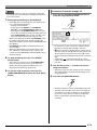
Using the Pitch Bend Wheel
The PITCH BEND wheel (S-1) lets you change the pitch of
notes you are playing by rotating the wheel forward or back.
Rotating the wheel away from you raises the pitch, while
rotating it towards you lowers it. Releasing the wheel causes
the pitch of the notes to return to normal automatically.
• The first tap of the L-12 (TAP) button will cause the
display shown below to appear.
• Do not have the pitch bend wheel rotated as you turn
on the keyboard.
• The tempo setting will change in accordance with your
tapping speed as soon as you tap the fourth time.
• The setting will be canceled if you release the R-13
(FUNCTION) button before tapping the L-12 (TAP)
button four times.
2. After setting the tempo by tapping, you then
can use the procedure under “To change the
tempo using the TEMPO buttons” (page E-19) to
make fine adjustments.
• You also can change the range of the pitch bend wheel
(bend range) globally or for a specific part. For details, see
“BendRange (Bend Range)” (page E-131) and “Part
Parameters” (page E-43).
Applying Vibrato to Notes
You can apply vibrato to notes you play on the keyboard (all
UPPER 1, UPPER 2, LOWER part notes) by hand. Vibrato is
applied to notes while the S-2 (MODULATION) button is
depressed. Releasing the button stops application of vibrato
(under initial default settings).
• Instead of vibrato, you can assign a different DSP effect to
the S-2 (MODULATION) button, if you want. For details,
see information about the following parameters in “DSP
Parameter Settings” (page E-35) and “Tone Parameter
Settings” (page E-48).
– Mod Button Assign (Modulation Button Assign)
– Mod Button On Value (Modulation Button On Value)
– Mod Button Off Value (Modulation Button Off Value)
E-20
Selecting and Playing a Tone
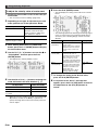
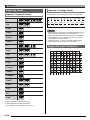
Selecting a Temperament and
Fine Tuning Its Scale
Use the scale function to select one of the 17 preset
temperaments (tunings) for the built-in sound source. You
also can fine tune each note of a scale (from C to B) in
one-cent units. After selecting one of the preset
temperaments, you can edit it to suit your particular needs.
You also can specify whether the current scale settings
(temperament setting and fine tuning adjustment) should be
applied to Auto Accompaniment (Accomp Scale).
• The settings you configure with the scale function are
retained even when the Digital Keyboard is turned off.
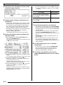
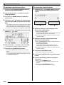
To select a preset scale
1. While holding down the R-13 (FUNCTION)
button, press the C-8 (SCALE) button to display
the scale screen, with the 0 located at
“Preset”.
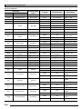
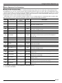
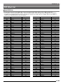
3. Use the dial or the R-14 (–, +) buttons to select a
temperament.
• Selecting a temperament other than 01: Equal will
cause the C indicator to appear on the display.
• The following shows the temperament numbers and
names that appear on the display.
Number
Screen Name
Preset Temperament
01
Equal
Equal temperament
02
Pure Major
Just major intonation
03
Pure Minor
Just minor intonation
04
Pythagorean
Pythagorean system
05
Kirnberger 3
Kirnberger III
06
Werckmeister
Werckmeister 1-3 (III)
07
Mean-Tone
Mean tone
08
Rast
Rast
09
Bayati
Bayati
10
Hijaz
Hijaz
11
Saba
Saba
12
Dashti
Dashti
13
Chahargah
Chahargah
14
Segah
Segah
15
Gurjari Todi
Gurjari Todi
16
Chandrakauns
Chandrakauns
17
Charukeshi
Charukeshi
4. Perform the following steps to specify the root
note of a temperament.
(1) Press the R-17 (i) button.
• This displays root note setting screen.
2. Press the R-16 (ENTER) button.
• This displays a preset temperament selection screen
like the one shown below.
(2) Use the dial or the R-14 (–, +) buttons to change the
root note (C to B).
• You can also use the keyboard to specify the root
note.
E-21
Selecting and Playing a Tone
5. When you are finished, press the R-15 (EXIT)
5. When you are finished making adjustments,
button twice.
press the R-15 (EXIT) button twice.
• This will return to the screen that was displayed before
you displayed the scale screen.
• This will return to the screen that was displayed before
you displayed the scale screen.
• The root note setting you specify here is retained, even if
you later change to a different preset temperament.
Fine Tuning a Scale
1. If required, perform the procedure under “To
select a preset scale” (page E-21) to select a
preset temperament.
2. While holding down the R-13 (FUNCTION)
Specifying whether the Current Scale
Settings Should be Applied to Auto
Accompaniment (Accomp Scale)
1. While holding down the R-13 (FUNCTION)
button, press the C-8 (SCALE) button to display
the scale screen.
2. Use the R-17 (i) button to move the 0 to
“AcmpScale”.
button, press the C-8 (SCALE) button to display
the scale screen.
3. Use the R-17 (y) button to move the 0 to
“FineTune” and then press the R-16 (ENTER)
button.
• This displays the scale fine tuning screen like the one
shown below.
3. Use the dial or the R-14 (–, +) buttons to change
the setting value.
To do this:
Select this setting:
Not apply scale settings to Auto
Accompaniment
oFF
Apply scale settings to Auto
Accompaniment
on
4. When the setting is the way you want, press the
R-15 (EXIT) button.
• This will return to the screen that was displayed before
you displayed the scale screen.
4. You can adjust the tuning of each individual
note in the scale.
(1) Use the R-17 (t) button to move the 0 to “Note”, and
then use the dial or R-14 (–, +) buttons to select the
name of the note you want to fine tune.
• You can also press a keyboard key to specify a
note.
(2) Use the R-17 (y) button to move the 0 to “Cent”, and
then use the dial or R-14 (–, +) buttons to fine tune the
selected note. You can fine tune a note within the
range of –99 through +99 cents.
• Adjusting all of the notes in the scale to 0 changes
the selected tuning to equal temperament. The
C indicator will be on the display when any note
in the scale has a value other than 0.
E-22
• The above scale on/off setting affects the Auto
Accompaniment bass part and Chord 1 through Chord 5
parts (A11 through A16). You also can turn scales settings
on or off for each individual part using the Part Parameter
(page E-43) “Scale (Part Scale Enable)” setting.
Selecting and Playing a Tone
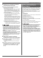
Playing Arpeggio Phrases
Automatically (Arpeggiator)
With the arpeggiator, you can play various arpeggios and
other phrases automatically by simply pressing keys on the
keyboard. You can select from a number of different
arpeggiator options, including playing arpeggios from a chord,
playing various phrases automatically, and more.
4. Press the R-18 (AUTO HARMONIZE/
ARPEGGIATOR) button.
• This causes a pointer indicator to appear on the display
next to ARPEGGIATOR.
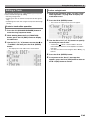
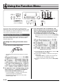
1. Hold down the R-18 (AUTO HARMONIZE/
ARPEGGIATOR) button until the type selection
screen shown below appears on the display.
Lit
5. Configure arpeggiator settings as required.
• The settings you can configure are described in the
table below. For information about how to configure
settings, see “To change the setting of a function menu
item” (page E-130).
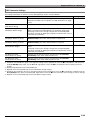
For information about this setting:
Go here:
ArpegHold
Whether arpeggio should be played
while keyboard keys are depressed or (Arpeggiator Hold)
(page E-131)
after the keys are released
Type number
The number of times arpeggio is
played within one beat
ArpegSpeed
(Arpeggiator
Speed) (page
E-132)
When the keyboard is split between
two tones, whether arpeggio should
be played when UPPER keyboard or
LOWER keyboard keys are pressed
ArpegPart
(Arpeggiator Part)
(page E-132)
Type name
2. Use the dial or R-14 (–, +) buttons to select the
arpeggiator type you want to use.
• You can select one of the arpeggiator types (013
through 162). Refer to the separate “Appendix” for
detailed information about supported arpeggiator types.
• When selecting the arpeggiator type, you can assign
the recommended tone for the currently displayed type
as the keyboard tone, by holding down the R-18 (AUTO
HARMONIZE/ARPEGGIATOR) button until a pointer
indicator starts to flash on the display next to
ARPEGGIATOR.
6. On the keyboard, play a chord or a single note.
• Arpeggio is played in accordance with the currently
selected arpeggiator type and the note(s) you play.
7. To turn off the arpeggiator, press the R-18
(AUTO HARMONIZE/ARPEGGIATOR) button
again.
• This causes the pointer indicator next to
ARPEGGIATOR to disappear from the display.
Flashing
• For information about type number 001 through 012,
see “Using Auto Harmonize” (page E-28).
3. Press the R-15 (EXIT) button.
• This exits the type selection screen.
E-23
Using Auto Accompaniment
L-4 - L-9
L-9
L-4
C-4
C-7
R-14
R-15
L-11
L-12
R-17
L-13
L-14 L-16 L-18
L-15 L-17
With Auto Accompaniment, simply select the accompaniment
rhythm you want and the matching accompaniment (drums,
guitar, etc.) will play automatically when you play a chord with
your left hand. It’s like having your own personal backup
group along with you wherever you go.
This Digital Keyboard has 250 built-in Auto Accompaniment
patterns, which are divided into five groups. You can edit
built-in rhythms to create your own original rhythms (called
“user rhythms”), which you can save in a sixth group. For
more information, see the separate “Appendix”.
R-18
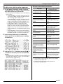
3. Use the dial to scroll through the rhythm
numbers until the one you want is displayed.
Example: Group B, Number 005
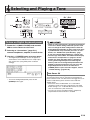
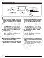
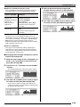
Playing an Auto Accompaniment
1. Refer to the separate “Appendix” to look up the
group and the number of the rhythm you want
to use.
2. Use the buttons from L-4 ([A] POPS/ROCK/
DANCE) to L-9 ([F] USER RHYTHMS) to select a
rhythm group.
• The L-9 ([F] USER RHYTHMS) button is for the user
rhythm group. For details, see “Using the Pattern
Sequencer” (page E-102).
Rhythm name
Group
Number
• You can also use the R-14 (–, +) buttons to select a
rhythm number. Holding down either button will scroll
through rhythm numbers at high speed. Pressing both
of the R-14 (–, +) buttons at the same time will select
001 in the currently selected group.
4. Use the L-11 (TEMPO w) and L-12 (TEMPO q)
buttons to adjust the tempo setting.
5. Press the L-18 (ACCOMP ON/OFF) button so the
D indicator is on the display.
• Each press of the button toggles accompaniment
between on (D indicator displayed) and off
(indicator not displayed).
• All accompaniment instrument parts sound while
accompaniment is on (D indicator displayed),
while only percussion instrument parts (drums, etc.)
sound while accompaniment is off (indicator not
displayed).
E-24
Using Auto Accompaniment
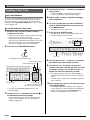
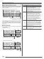
6. Press the L-16 (SYNCHRO/ENDING) button.
• This enters synchro standby (Auto Accompaniment
waiting for you to play a chord), with the F
indicator flashing on the display. The flashing F
indicator means that the normal Auto Accompaniment
pattern is standing by.
7. You also can use the buttons described below
to change to intro or variation pattern standby.
To enter synchro
standby for this
pattern:
Display
Indicator:
Press this button:
E
flashing
Intro
L-13 (INTRO)
Variation
L-15 (VARIATION/ H
FILL-IN)
flashing
For details about intro and variation patterns, see “Modifying
Auto Accompaniment Patterns” (page E-27).
10. When you are finished, press the L-17 (START/
STOP) button again to stop Auto
Accompaniment.
• Pressing the L-16 (SYNCHRO/ENDING) button instead
of the L-17 (START/STOP) button will play an ending
pattern before stopping Auto Accompaniment play. For
details about ending patterns, see “Modifying Auto
Accompaniment Patterns” (page E-27).
• You can use the following procedure to adjust the volume
level of the Auto Accompaniment, without affecting the
volume of Digital Keyboard output. For details, see
“AccompVol. (Auto Accompaniment Volume)” (page
E-133).
• You can change the size of the chord keyboard by using
the split feature to move the split point (page E-17). The
keyboard keys to the left of the split point make up the
chord keyboard.
8. Play the chord you want on the chord keyboard
(left keyboard keys).
• Auto Accompaniment will start playing when you play
the chord.
• To start percussion part play without playing a chord,
press the L-17 (START/STOP) button.
Example: To play a C chord
Chord keyboard
Melody keyboard
• The chord root and type that corresponds to the keys
you press appear in the chord area of the display.
9. Play other chords with your left hand as you
play the melody with your right hand.
• You can use “CASIO Chord” or other simplified chord
fingering modes to play chords. For details, see
“Selecting a Chord Fingering Mode” in the following
section.
• You can use the L-14 (NORMAL/FILL-IN) and L-15
(VARIATION/FILL-IN) buttons to modify
accompaniment patterns. For details, see “Modifying
Auto Accompaniment Patterns” (page E-27).
E-25
Using Auto Accompaniment
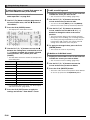
Selecting a Chord Fingering Mode
While Auto Accompaniment is playing, you use the chord
keyboard to specify the chord root and type. The area of the
keyboard to the left of the split point (page E-17) is the chord
keyboard. The illustration below shows the chord keyboard
range under WK-7500 initial default settings.
Chord keyboard
Melody Keyboard
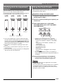
You can select from among the following five chord fingering
modes.
1: Fingered 1
2: Fingered 2
3: Fingered 3
4: CASIO Chord
5: Full Range
■ Fingered 1, 2, 3
With these three chord fingering modes, you play chords on
the chord keyboard using their normal chord fingerings. Some
chord forms are abbreviated, and can be fingered with one or
two keys. For information about the types of chords you can
finger and their fingerings, see the “Fingering Guide” (page
E-160).
Fingered 1 : Play the component notes of the chord on the
keyboard.
Fingered 2 : Unlike Fingered 1, 6th input is not possible with
this mode.
Fingered 3 : Unlike Fingered 1, this mode allows input of
fraction chords with the lowest keyboard note as
the bass note.
■ CASIO Chord
With “CASIO Chord”, you can use simplified fingerings to play
the four types of chords described below.
Chord Type
Example
C (C Major)
Major Chords
Press one key, whose note
Note
corresponds to the chord
name
name.
• To play C Major, press any
C key in the chord keyboard.
The octave of the note does
not matter.
C C#DE b E F F#GAb A Bb B C C#DE b E F
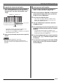
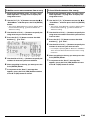
To select a chord fingering mode
1. Hold down the L-18 (ACCOMP ON/OFF) button
until the chord fingering mode selection screen
shown below appears on the display.
Chord fingering mode
2. Use the dial or R-14 (–, +) buttons to select a
chord fingering mode.
3. Press the L-18 (ACCOMP ON/OFF) button or the
R-15 (EXIT) button.
• This exits the chord fingering mode selection screen.
Minor Chords
Press the chord keyboard key
that corresponds to the major
chord, while also pressing one
other chord keyboard key to
the right.
Cm (C minor)
Seventh Chords
Press the chord keyboard key
that corresponds to the major
chord, while also pressing two
other chord keyboard keys to
the right.
C7 (C seventh)
Minor Seventh Chords
Press the chord keyboard key
that corresponds to the major
chord, while also pressing
three other chord keyboard
keys to the right.
Cm7 (C minor seventh)
C C#DE b E F F#GAb A Bb B C C#DE b E F
C C#DE b E F F#GAb A Bb B C C#DE b E F
C C#DE b E F F#GAb A Bb B C C#DE b E F
When pressing more than one chord keyboard key, it makes
no difference whether the additional keys are white or black.
■ Full Range Chord
With this chord fingering mode, you can use the full range of
the keyboard to play chords and the melody. For information
about the types of chords you can finger and their fingerings,
see the “Fingering Guide” (page E-160).
E-26
Using Auto Accompaniment
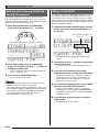
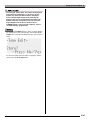
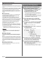
Modifying Auto Accompaniment
Patterns
There are six different Auto Accompaniment patterns, shown
below. You can switch between patterns during
accompaniment play and even modify patterns. Use buttons
L-13 through L-16 to select the pattern you want.
L-13
L-14
L-15
L-16
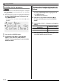
Using One-Touch Presets
One-Touch Preset gives you one-touch access to tone and
tempo settings that go well with the currently selected Auto
Accompaniment rhythm pattern.
To perform using a one-touch preset
1. If rhythm is playing, press the L-17 (START/
STOP) button to stop it.
2. Select the rhythm (excluding user rhythms) you
want to use.
3. While holding down the L-8 ([E] PIANO
RHYTHMS) button, press the L-9 ([F] USER
RHYTHMS) button.
Intro *1
Normal
Normal fill-in *2
Variation
Ending *4
Variation fill-in *3
*1 Press at the beginning of a song. Accompaniment play
proceeds with the normal pattern after the intro pattern is
complete. Pressing the L-15 (VARIATION/FILL-IN) button
before pressing this button will proceed with the variation
pattern after the intro pattern is complete.
*2 Press while a normal pattern is playing to insert a fill-in
pattern.
*3 Press while a variation pattern is playing to insert a fill-in
variation pattern.
*4 Press at the end of a song. This will play an ending pattern
and then stop Auto Accompaniment.
• Settings for the following items are configured
appropriately for the rhythm you selected in step 2.
– Tones for the UPPER 1, UPPER 2, and LOWER
parts
– Octave shift for the UPPER 1, UPPER 2, and
LOWER parts
– Layer and split on/off
– Accompaniment on/off
– Reverb on/off and type
– Chorus type
– Auto harmonize or Arpeggiator on/off and type
– Tempo
• Also, the F indicator flashes on the display to
indicate that the normal Auto Accompaniment pattern is
standing by.
4. Start playing something on the keyboard.
• Perform the procedure starting from step 7 under
“Playing an Auto Accompaniment” (page E-24).
• One-Touch Presets are not supported for user rhythms
(F:001 through F:100).
• You can recall one-touch preset settings even if a rhythm is
already playing when you perform step 3 of the above
procedure. In this case, rhythm play will continue without
going into synchro standby.
E-27
Using Auto Accompaniment
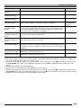
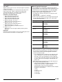
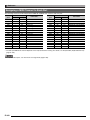
Using Auto Harmonize
Auto harmonize lets you add harmony to melody notes you
play with your right hand. You can select any one of 12 Auto
harmonize settings.
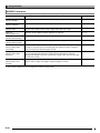
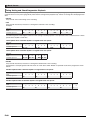
Type
Number
Type
Name
009
4WayOpen
Adds 3-note open harmony, for a
total of four notes.
010
4WayClos
Adds 3-note close harmony, for a
total of four notes.
011
Block
Adds block chord notes.
012
Big Band
Adds big band style harmony.
To play using auto harmonize
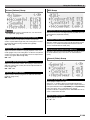
1. Hold down the R-18 (AUTO HARMONIZE/
ARPEGGIATOR) button until the type selection
screen shown below appears on the display.
Description
• For information about type numbers greater than 012,
see “Playing Arpeggio Phrases Automatically
(Arpeggiator)” (page E-23).
3. Press the R-15 (EXIT) button.
• This exits the type selection screen.
4. Press the R-18 (AUTO HARMONIZE/
ARPEGGIATOR) button.
• This causes a pointer indicator to appear on the display
next to AUTO HARMONIZE.
Lit
Type number
Type name
2. Use the dial or R-14 (–, +) buttons to select the
auto harmonize type you want to use.
• You can select one of the type numbers (001 through
012) described in the table below.
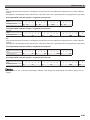
Type
Number
Type
Name
Description
001
Duet 1
Adds close (separated by two to
four degrees) one-note harmony
below the melody note.
002
Duet 2
Adds open (separated by more
than 4 to 6 degrees) 1-note
harmony below the melody note.
003
Country
Adds country style harmony.
004
Octave
Adds the note from the next lower
octave.
005
5th
Adds the fifth degree note.
006
3WayOpen
Adds 2-note open harmony, for a
total of three notes.
007
3WayClos
Adds 2-note close harmony, for a
total of three notes.
008
Strings
Adds harmony that is optimal for
strings.
E-28
5. Play chords and the melody on the keyboard.
• Harmony will be added to your melody notes based on
the chords you play.
6. To turn off auto harmonize, press the R-18
(AUTO HARMONIZE/ARPEGGIATOR) button
again.
• This causes the pointer indicator next to AUTO
HARMONIZE to disappear.
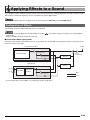
Applying Effects to a Sound
You can apply a variety of different acoustic effects to the sounds produced by the Digital Keyboard. The built-in effects include a
wide variety of variations that give you access to a selection of general digital effects.
• The Digital Keyboard also lets you apply effects to input from the T-5 (INST IN) jack and T-8 (MIC IN) jack.
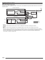
Configuration of Effects
The following shows how Digital Keyboard effects are configured.
• Items such as “Reverb Send” that are indicated by the symbol
(page E-36).
• Chorus and DSP cannot be used at the same time.
are all mixer settings. For details, see “Using the Mixer”
■ Chorus Effect Mode Configuration
The chorus effect mode is enabled while “Chorus” is selected for the “Chorus/DSP” effect parameter. Chorus and reverb can be
used in the chorus effect mode.
Part A01-A16, B01-B16
Output
Part Volume/Pan
Reverb Send
Tone Generator
Chorus Send
Master
Volume/Pan
Reverb
External Input
Chorus
Volume/Pan
Mic In
Noise Gate
Inst In
Auto Level
Control
Reverb Send
Chorus Send
Mono
Stereo
• For information about “Chorus/DSP”, see “Selecting an Effect” (page E-31).
E-29
Applying Effects to a Sound
■ DSP Effect Mode Configuration
The DSP effect mode is enabled while “DSP” is selected for the “Chorus/DSP”effect parameter. DSP and reverb can be used in the
DSP effect mode.
Part A01-A16, B01-B16
Output
Part Volume/Pan
Tone Generator
DSP
Off
On
Master
Volume/Pan
Reverb Send
Reverb
DSP Reverb Send
External Input
DSP
Volume/Pan
DSP Volume/Pan
Mic In
Noise
Gate
Inst In
Auto Level DSP
Control
Off
On
Reverb Send
Mono
Stereo
• Reverb
This type of effect simulates acoustic spaces. There are 10 different reverb effects, including room and hall.
• Chorus
This type of effect increases the depth of notes and applies vibrato to notes. There are five different chorus effects.
• DSP
This type of effect is inserted between the sound source and output. There are a total of 100 different DSP effects, including
distortion and modulation. You also can transfer DSP effects from a computer or create DSP data on the Digital Keyboard, and
store up to 100 user DSP effects in Digital Keyboard memory. For details, see “Creating a User DSP” (page E-33) and
“Connecting to a Computer” (page E-145).
E-30
Applying Effects to a Sound
C-7
R-15
R-13
R-14
R-16
R-17
Selecting an Effect
Effects are divided among different types (reverb, chorus,
DSP), so first you need to use the procedure below to select
an effect type.
To add reverb to sounds
1. While holding down the R-13 (FUNCTION)
button, press the C-7 (EFFECT) button.
• A pointer indicator is displayed next to REVERB when
anything other than “oFF” is selected for the reverb type.
The pointer indicator is not displayed next to REVERB
when “oFF” is selected.
• You can use Reverb Send to adjust how reverb is applied
to the tone of each keyboard or Auto Accompaniment part.
For details, see “Using the Mixer” (page E-36).
To add the chorus effect to sounds
1. While holding down the R-13 (FUNCTION)
button, press the C-7 (EFFECT) button to
display the effect setting screen.
• This displays the effect setting screen shown below.
2. Use the dial or R-14 (–, +) buttons to select the
reverb type you want to use.
• Refer to the separate “Appendix” for information about
supported reverb types.
• To turn off reverb, select “oFF” here.
3. Press the C-7 (EFFECT) button or the R-15
(EXIT) button.
• This exits the effect setting screen.
E-31
Applying Effects to a Sound
2. If you want, use the R-17 (t, y) buttons to
move the thick brackets (%) to the “DSP
Disable”setting, and then use the R-14 (–, +)
buttons to change the setting to “on”.
• For more information about this setting, see the
“Important!” note below.
• If you turning on the “DSP Disable” setting, you should
skip steps 3 and 4 below.
8. Use the mixer to adjust the chorus send of the
part to which you want to apply chorus.
• You can use “Cho.Send” (Part Chorus Send, page
E-43) to adjust how chorus is applied to the tone of
each keyboard or Auto Accompaniment part. The initial
default setting is 0 for the chorus send of all parts, so
change the settings to a chorus send value greater than
0 for all parts to which you want to apply the chorus
effect. For details, see “Using the Mixer” (page E-36).
3. Use the R-17 (t, y) buttons to move the thick
brackets (%) to the “Chorus/DSP” setting.
4. Use the R-14 (–, +) buttons to select “Chorus”.
• This enters the chorus effect mode, which enables the
use of the chorus effect.
5. Use the R-17 (t, y) buttons to move the thick
• Selecting a tone with DSP causes the “Chorus/DSP”
setting to change automatically to the “DSP” (DSP
effect mode), so the chorus effect will not be available.
If you want the chorus effect always to be available,
change the “DSP Disable” setting to “on”. This will
keep the Digital Keyboard in the chorus effect mode.
brackets (%) to the “Chorus” setting.
• A pointer indicator is displayed next to CHORUS when
“Chorus” is selected for the “Chorus/DSP” setting. The
pointer indicator is not displayed next to CHORUS when
“oFF” is selected for the chorus type or when “DSP” is
selected for the “Chorus/DSP” setting.
• Selecting “Chorus” for the “Chorus/DSP” setting will cause
the “DSP Line” (Part DSP Line, page E-43) setting for all
parts to be changed to “oFF”.
6. Use the dial or R-14 (–, +) buttons to select the
chorus type you want to use.
• Refer to the separate “Appendix” for information about
supported chorus types.
To use a DSP
1. While holding down the R-13 (FUNCTION)
button, press the C-7 (EFFECT) button to
display the effect setting screen.
7. Press the C-7 (EFFECT) button or the R-15
(EXIT) button.
• This exits the effect setting screen.
• Check to make sure that the “DSP Disable” setting is
“oFF”. If it is “on”, change it to “oFF”.
2. Use the R-17 (t, y) buttons to move the thick
brackets (%) to “Chorus/DSP”.
3. Use the R-14 (–, +) buttons to select “DSP”.
• This enters the DSP effect mode, which enables the
use of the DSP effect.
E-32
Applying Effects to a Sound
4. Use the R-17 (t, y) buttons to move the thick
brackets (%) to the “DSP” setting.
• This causes the number and name of the currently
selected preset DSP to appear within the thick brackets
(%) on the display.
Creating a User DSP
You can create a user DSP by editing one of the built-in
preset DSPs.
User DSP Numbers
DSP areas numbered 101 through 200 are for storage of user
DSPs. You can have up to 100 user DSPs stored in memory
at one time. To recall a stored user DSP, use the same
procedure you use to recall a preset DSP. See “To use a
DSP” (page E-32) for more information.
To create and save a user DSP
5. Use the dial or R-14 (–, +) buttons to select the
preset DSP you want to use.
• DSPs with the leading numbers 001 through 100 (and
“ton”) are preset DSPs. See “Preset DSP List” (page
E-155) for information about preset DSP numbers and
names.
• DSP types with the leading numbers 101 through 200
are user DSPs. For details, see “Creating a User DSP”
(page E-33).
1. Referring to the “DSP Type List” (page E-156),
select the DSP type you want to edit in order to
create your user DSP.
2. Use the R-17 (y) button to move the 0 to “DSP
Edit”.
6. Press the C-7 (EFFECT) button or the R-15
(EXIT) button.
• This exits the effect setting screen.
• A pointer indicator is displayed next to DSP when “DSP” is
selected for the “Chorus/DSP” setting.
• Maximum polyphony is reduced by a maximum of two
notes when playing on the keyboard while a DSP is in use.
• You also can adjust how a DSP is applied (DSP output
enabled/disabled, DSP output volume, DSP output pan,
etc.) For details, see “Using the Mixer” (page E-36).
3. Press the R-16 (ENTER) button.
• This displays page one of the DSP editor screen. Use
this screen to select the DSP type.
Total number of pages
Currently displayed page
DSP type
DSP number
• You can use the R-17 (u, i) buttons to scroll
between pages.
4. Use the dial or R-14 (–, +) buttons to select a
DSP type.
E-33
Applying Effects to a Sound
5. Use the R-17 (t, y) buttons to move the 0 to
the parameter you want to change.
10. Use the dial or R-14 (–, +) buttons to select the
destination user DSP number you want.
11. Use the R-17 (u, i) buttons to move the
cursor to the name character position you want
to change, and then use the dial or R-14 (–, +)
buttons to select the character you want.
• For information about the operation and the setting
range of each parameter, see “DSP Parameter
Settings” (page E-35).
6. Use the dial or R-14 (–, +) buttons to change the
setting value.
• Pressing the R-14 (–, +) buttons at the same time
returns a parameter to its initial default setting.
• Changing the DSP parameter while a note is being
output from the Digital Keyboard may cause noise to be
generated. This does not indicate malfunction.
7. Repeat steps 5 and 6 as required to configure
other parameters.
8. Press the R-15 (EXIT) button.
• This displays the confirmation screen shown below.
To cancel the editor operation without saving the edited
results, press the R-14 (NO) button.
9. Press the R-14 (YES) button.
• This displays a screen for specifying the destination
user DSP number and DSP name.
Destination user DSP number
DSP name
E-34
• See “Supported Input Characters” (page E-160) for
information about the characters you can input for the
name.
• To input a space, press both of the R-14 (–, +) buttons
at the same time.
12. After everything is the way you want, press the
R-16 (ENTER) button.
• A message (Replace?) will appear on the display to
confirm whether you want to replace the existing data
with the new data. Press the R-14 (YES) button to
replace the existing data with the new data.
• The message “Please Wait” will remain on the display
while a data save operation is in progress. Do not
perform any other operation while it is displayed.
Turning off the Digital Keyboard or removing the
memory card can cause Digital Keyboard data to be
deleted or become corrupted. It also can cause the
Digital Keyboard to fail to turn on when the L-1
(POWER) button is pressed. If this happens, refer to
“Troubleshooting” (page E-150).
Applying Effects to a Sound
DSP Parameter Settings
The table below shows the parameters that can be configured on the DSP editor screen.
The settings marked with an asterisk (*) in the “Setting Range” column are initial defaults.
Parameter Name
Description
Setting Range
Parameters 1 through 8
The number of parameters and settings available for each parameter
depends on the DSP type. For details, see “DSP Parameter List” (page
E-157).
–
DSP RevSend
(DSP Reverb Send)
Specifies how much of the post-DSP sound should be sent to reverb.
0 - 40* - 127
Mod Button Assign*1
(Modulation Button Assign)
Specifies the function assigned to the S-2 (MODULATION) button when oFF*, 1 - 8*2
“DSP” is selected for the “Mod Setting” tone parameter (page E-49).
Specifying a value from 1 through 8 assigns the corresponding DSP
parameter (1 through 8). Nothing is assigned to the button when “oFF” is
selected for this parameter.
Mod Button On Value*1
(Modulation Button On Value)
Specifies how the function currently assigned to the S-2
(MODULATION) button works while the button is depressed.
*3
Mod Button Off Value*1
(Modulation Button Off Value)
Specifies how the function currently assigned to the S-2
(MODULATION) button works while the button is released.
*3
Rot Button Assign*4
(Rotary Button Assign)
oFF*, 1 - 8*2
Specifies the function assigned to the D-1 (ROTARY SLOW/FAST)
button.
Specifying a value from 1 through 8 assigns the corresponding DSP
parameter (1 through 8). Nothing is assigned to the button when “oFF” is
selected for this parameter.
Rot Button On Value*4
(Rotary Button On Value)
Specifies how the function currently assigned to the D-1 (ROTARY
SLOW/FAST) button works while the button is lit.
*5
Rot Button Off Value*4
(Rotary Button Off Value)
Specifies how the function currently assigned to the D-1 (ROTARY
SLOW/FAST) button works while the button is unlit.
*5
*1 Included in the “Mod Button” group. To change the settings of these parameters, move the 0 to “Mod Button” and then press
the R-16 (ENTER) button. Next, use the R-17 (t, y) buttons to move the 0 to the parameter whose setting you want to
change.
*2 Setting range depends on the selected DSP type.
*3 Depends on the selected DSP type and the “Mod Button Assign” setting.
*4 Included in the “Rot Button” group. To change the settings of these parameters, move the 0 to “Rot Button” and then press the
R-16 (ENTER) button. Next, use the R-17 (t, y) buttons to move the 0 to the parameter whose setting you want to change.
*5 Depends on the selected DSP type and the “Rot Button Assign” setting.
E-35
Using the Mixer
R-15
R-13
R-14
R-16
C-7
R-17
C-17
This
part:
Mixer Overview
The sound source of this Digital Keyboard is capable of
sounding up to 32 individual parts simultaneously. Each part
can be controlled individually, and each part can be
configured to sound a different musical instrument. Different
tones can be assigned to each part when using layer and split
to sound multiple tones at the same time, and to sound
multiple instruments at the same time with Auto
Accompaniment.
The mixer can be used to assign such tones and to configure
other settings for each part, and to configure global effect
settings applied to all parts. The mixer provides you with the
means to make fine adjustments to a wide variety of settings,
from note generation to note output.
How Parts are Organized
This Digital Keyboard has a total of 32 parts: A01 through
A16, and B01 through B16. Each part has a specific purpose.
Use the table below as a reference to determine the purpose
of each part when using the mixer to configure the settings of
a part.
This
part:
Is used for this:
A01
Manual play UPPER 1 part
A02
Manual play UPPER 2 part
A03
Manual play LOWER part
A04
Auto harmonize tone
A05
UPPER 1 part*1
A06
UPPER 2 part*2
A07
LOWER part*3
A08
Metronome sound
E-36
Go here for more
information:
“Layering and Splitting
Tones” (page E-15)
“Using Auto
Harmonize” (page
E-28)
“Using the Song
Sequencer” (page
E-68)
“Using the Metronome”
(page E-19)
Is used for this:
A09
Auto Accompaniment
percussion part
A10
Auto Accompaniment drums
part
A11
Auto Accompaniment bass
part
Go here for more
information:
“Using Auto
Accompaniment” (page
E-24)
A12 to Auto Accompaniment Chord
A16 1 part through Chord 5 part
Song sequencer track B01
through B16, tracks 1 through
B01 to 16 during playback of a MIDI
B16 file from a memory card, CH1
through CH16 during MIDI
receive
“Using the Song
Sequencer” (page
E-68), “Playing a Music
File from a Memory
Card” (page E-142),
“Connecting to a
Computer” (page
E-145)
*1 UPPER 1 part recorded to the song sequencer system
track.
*2 UPPER 2 part recorded to the song sequencer system
track.
*3 LOWER part recorded to the song sequencer system
track.
Using the Mixer
Mixer Operation
To change mixer parameters
• When you move the thick brackets (%) to one of the
setting values of a part parameter, all of the part
parameter values of the Group (A or B) to which the
part belongs are indicated by level meter black boxes.
1. Press the C-7 (MIXER) button.
• This causes the mixer screen to appear.
Currently selected setting
(MASTER, DSP, MIC/INST, or A01 to A16/B01 to B16)
Parameter/Setting value
Currently selected setting part
(when currently selected setting is A01 to A16/B01 to B16)
4. Use the dial or R-14 (–, +) buttons to change the
setting value.
• Pressing the R-14 (–, +) buttons at the same time
returns a parameter to its initial default setting.
• You also can change the settings of parameters using
the D-1 (PART/COMMON), D-2 (GROUP A/B), and
D-3 (1-8/9-16) buttons, and sliders D-4 (1/9/EXT) to
D-12 (MASTER). For more information, see “Using the
Sliders to Change Parameter Settings” (page E-38).
• While the “Part” (part on/off) setting of a part parameter
is being configured, pressing both of the R-14 (–, +)
buttons at the same time will change the setting to “Sol”
(Solo). For details, see “Part Parameters” (page E-43).
5. Repeat steps 2 through 4 as required to
configure other parameters.
2. Use the R-17 (u, i) buttons to select the
mixer parameter you want to change.
• You can select master (MASTER), effect (DSP),
microphone input (MIC/INST), or a part (A01 through
A16, B01 through B16). The currently selected setting
is shown in the line two of the display.
• While a part is selected, you can toggle between Group
A and Group B by pressing both of the R-17 (u, i)
buttons at the same time.
3. Use the R-17 (t, y) buttons to move the thick
brackets (%) to the parameter you want to
change.
• The parameters that can be configured depend on the
currently selected setting. For details, refer to the
sections shown in the table below.
When this setting is
selected:
6. To exit the mixer, press the C-7 (MIXER) button
or the R-15 (EXIT) button.
• This exits the mixer screen.
• While master (MASTER), effect (DSP) or microphone input
(MIC/INST) is selected in step 2 above for setting, you also
can perform normal keyboard play (play using layer, split,
and Auto Accompaniment).
• While an individual part (A01 through A16, B01 through
B16) is selected in step 2 above for setting, pressing a
keyboard key will sound only notes of the selected part. All
other types of performance operations (layer, split, Auto
Accompaniment, etc.) are disabled.
These parameters can be
configured:
MASTER
MASTER parameters
(page E-41)
MIC/INST
MIC/INST parameters
(page E-42)
DSP
DSP parameters (page E-41)
A01 to A16/B01 to B16
Part parameters (page E-43)
E-37
Using the Mixer
Using the Sliders to Change Parameter Settings
While the mixer screen is displayed, use sliders D-4 (1/9/EXT) to D-12 (MASTER) to change the displayed parameter settings. The
D-1 (PART/COMMON), D-2 (GROUP A/B) and D-3 (1-8/9-16) buttons are used to specify the parts that correspond to sliders
D-4 (1/9/EXT) to D-11 (8/16).
D-1 D-2 D-3
D-4
D-5
D-6
D-7
D-8
D-9 D-10 D-11 D-12
The following describes the operation of these buttons and sliders while the mixer screen is displayed.
● D-1 (PART/COMMON) button:
Each press toggles the mixer screen between master parameter settings (MASTER) and the settings of one of the part (A01
through A16, B01 through B16) parameters.
● D-2 (GROUP A/B) button:
Each press toggles the part parameter setting screen between one of the parts in group L (A01 through A16) and one of the
parts in group M (B01 through B16).
● D-3 (1-8/9-16) button:
Each press toggles the parts that correspond to parameter operations by sliders D-4 (1/9/EXT) to D-11 (8/6) between A01
through A08 (or B01 through B08) and A09 through A16 (or B09 through B16).
E-38
Using the Mixer
● Sliders D-4 (1/9/EXT) through D-11 (8/16):
Allow configuration of the following parameter settings in
accordance with the currently displayed mixer setting.
When this setting
screen is displayed:
These parameter settings can be
configured:
MASTER parameters
(page E-41),
MIC/INST parameters
(page E-42),
DSP parameters
(page E-41)
Slider D-4 (1/9/EXT):
MIC/INST parameters*
Slider D-5 (2/10/DSP):
DSP parameters*
Sliders D-6 (3/11) to D-11 (8/16):
Parameters of part assigned to
each slider*
Part Parameters
(page E-43)
Sliders D-4 (1/9/EXT) to D-11
(8/16):
Parameters of part assigned to
each slider*
4. Next, to adjust the volumes of parts A09
through A16, press the D-3 (1-8/9-16) button.
5. Use sliders D-4 (1/9/EXT) to D-11 (8/16) to adjust
the volume of each part (A09 through A16).
* Operating a slider whose setting does not correspond to
anything on the currently displayed setting screen will
automatically switch to the setting screen that corresponds
to the slider. For example, if you operate slider D-4 (1/9/
EXT) while the master parameter setting screen is
displayed, the display will automatically switch to the MIC/
INST parameter setting screen.
● Slider D-12 (MASTER):
Changes the master parameter setting. Operating this
slider while any screen other than the master parameter
setting screen is displayed will automatically switch to the
master parameter setting screen.
■ Setting Operation Example: To adjust the volume
of parts A01 through A16
1. While the mixer setting screen is displayed, use
the R-17 (u, i) buttons to select one of the
parts (A01 through A08).
2. Use the R-17 (t, y) buttons to move the 0 to
“Volume”.
• This enables modification of the part volume setting.
3. Use sliders D-4 (1/9/EXT) to D-11 (8/16) to adjust
the volume of each part (A01 through A08).
• As you move a slider to change a part volume, the
setting is reflected in the value inside the thick brackets
(%) and on the level meter.
E-39
Using the Mixer
To initialize all mixer parameters
• For details about how initial default settings are configured
when you perform the following procedure, see “Parameter
List” (page E-163).
1. While the mixer screen is displayed, hold down
the R-13 (FUNCTION) button as you press the
C-17 (MENU) button.
• This displays the mixer menu screen with the 0 next to
“Initialize”.
To change the information displayed by the
level meter while configuring part parameter
settings
1. While the mixer screen is displayed, hold down
the R-13 (FUNCTION) button as you press the
C-17 (MENU) button.
• This displays the mixer menu.
2. Use the R-17 (y) button to move the 0 to
“Display” and then press the R-16 (ENTER)
button.
3. Use the dial or R-14 (–, +) buttons to change the
setting.
To select display of this
information:
2. Press the R-16 (ENTER) button.
3. In response to the “Sure?” message that
appears, press the R-14 (YES) button to
initialize all mixer parameters or the R-14 (NO)
button to cancel.
E-40
Select this setting:
Part parameter setting values
Param
Volume level
Meter
4. After the setting is the way you want, press the
R-15 (EXIT) button to exit the menu.
Using the Mixer
Mixer Parameter Settings
The tables below show the parameters that can be configured on the mixer screen.
The settings marked with an asterisk (*) in the “Setting Range” column are initial defaults.
MASTER Parameters
MASTER parameters include items for adjusting the volume level, pan position, and other settings that are applied globally to all
parts.
Parameter Name
Description
Setting Range
Volume
(Master Volume)
Specifies the maximum volume level of Digital Keyboard output.
The level set here is the maximum level that can be set with the L-2 (MAIN
VOLUME) knob.
0 to 127*
Pan
(Master Pan)
Specifies the stereo pan position of all sound output by the Digital Keyboard.
0 indicates the center, while a smaller values shifts to the left and a larger value
shifts to the right.
–64 to 0* to +63
DSP Parameters
DSP parameters include DSP-related settings that are applied globally to all parts.
• DSP parameter setting cannot be changed while “on” is selected for the “DSP Disable” effect setting. See “To add the
chorus effect to sounds” (page E-31) for information about “DSP Disable”. If you want to change DSP parameter
settings, change the “DSP Disable” setting to “oFF”.
Parameter Name
Description
Setting Range
Cho/DSP
(Chorus/DSP)
Specifies whether the Digital Keyboard’s sound source should go through
the chorus or DSP.*1 This setting item is linked to the “Chorus/DSP”*2 item
on the effect setting screen. The settings below cannot be configured
whenever this parameter is “Chorus”.
Chorus*, DSP
Part
(DSP Output Enable)
Specifies if a note should be output (on) or not output (oFF) after it passes
through the DSP.
oFF, on*
Volume
(DSP Output Volume)
Specifies the post-DSP volume level.*1
0 to 127*
Pan
(DSP Output Pan)
Specifies the post-DSP send stereo pan position. 0 indicates the center,
while a smaller values shifts to the left and a larger value shifts to the right.
–64 to 0* to +63
Rev.Send
(DSP Output Reverb Send)
Specifies how much reverb is applied to the post-DSP send note.
0 to 40* to 127
*1 See the block diagram under “Configuration of Effects” (page E-29).
*2 See “To add the chorus effect to sounds” (page E-31) and “To use a DSP” (page E-32).
E-41
Using the Mixer
MIC/INST Parameters
MIC/INST parameters include settings related to the T-5 (INST IN) and T-8 (MIC IN) terminals.
Parameter Name
Description
Setting Range
Part
(Mic/Inst Enable)
Specifies if sound input should be output (on) or not output (oFF).
oFF, on*
Volume
(Mic/Inst Volume)*1
Specifies the volume level of sound input.
0 to 80* to 127
Pan
(Mic/Inst Pan)
Specifies the stereo pan position of sound input. 0 indicates the center, while a
smaller values shifts to the left and a larger value shifts to the right.
–64 to 0* to +63
DSP Line
(Mic/Inst DSP Line)
Specifies whether DSP should be applied to sound input.
oFF*, on
Rev.Send
(Mic/Inst Reverb Send)
Specifies how much reverb is applied to sound input.
0 to 40* to 127
Cho.Send
(Mic/Inst Chorus Send)
Specifies how much chorus effect is applied to sound input.
0* to 127
N.Thresh
(Mic/Inst Noise Gate
Threshold)*1
Cuts low-volume input sounds, which decreases noise. Allows a signal to pass
through if it is above the set threshold (gate open). Does not allow a signal to
pass if it is below the threshold (gate closed).
0 to 20* to 127
N.Release
(Mic/Inst Noise Gate
Release)*1
Specifies the amount of time for the gate to go from open to fully closed when an
input sound signal falls below the threshold value specified by “N.Thresh”.
Setting 0 will abruptly cut off the sound, while a larger value will cause the gate
to close more slowly.
0 to 64* to 127
Auto Level
(Mic/Inst Auto Level
Control)*1
Automatically controls the input signal level. Selecting “oFF” disables this
feature, while a larger value applies a greater degree of control.
oFF*, 1 to 3
*1 See the block diagram under “Configuration of Effects” (page E-29).
E-42
B
Using the Mixer
Part Parameters
Part parameters include setting items that can be adjusted for parts A01 through A16 and B01 through B16.
Parameter Name
Description
Setting Range
TONE
(Part Tone)
Specifies a tone for each part. When configuring this parameter, you can use the
buttons R-1 ([A] PIANO) through R-12 ([L] DRAWBAR ORGAN) to select a tone
group.
A:001 to L:100
Part
(Part On/Off)
Specifies if the notes of a particular part should be output (on) or not output (oFF).
When a part is turned on, the part number is displayed along the bottom of the level
meter. Part numbers are not displayed for parts that are turned off.
When playing back a MIDI file or song sequencer song, a “Sol” (Solo) option can be
specified to play a specific part only. To switch to “Sol”, press both R-14 (–, +)
buttons at the same time.
oFF, on*
Volume
(Part Volume)
Specifies the volume level of each part.
0 to 127*
Pan
(Part Pan)
Specifies the stereo pan position of each part. 0 indicates the center, while a smaller
values shifts to the left and a larger value shifts to the right.
–64 to 0* to +63
CoarseTune
(Part Coarse Tune)
Specifies, in semitone steps, the pitch of the notes of each part.
–24 to 0* to +24
FineTune
(Part Fine Tune)
Specifies, in cent steps, the pitch of the notes of each part.
–99 to 0* to +99
BendRange
(Part Bend Range)
Specifies the bend range of each part.
0 to 2* to 24
DSP Line
(Part DSP Line)
Specifies whether DSP should be applied to each part. Changing this setting from
“oFF” to “on” automatically switches the “Cho/DSP” setting (page E-41) to “DSP”.
oFF*, on
Rev.Send
(Part Reverb Send)
Specifies how much reverb is applied to each part.
No reverb is applied at all when this setting is 0, while maximum reverb is applied
when it is 127.
0 to 40* to 127
Cho.Send
(Part Chorus Send)
Specifies how much chorus is applied to each part.
No chorus is applied at all when this setting is 0, while maximum chorus is applied
when it is 127.
0* to 127
Scale
(Part Scale Enable)
Specifies whether scale (page E-21) settings should be applied (on) or should not be
applied (oFF). Equal temperament is applied to parts when this setting is “oFF”.
oFF*, on
B
E-43
Using the Tone Editor
R-15
R-13
R-14
R-16
C-8
R-17
C-17
You can create a user tone by editing one of the built-in preset
tones.
• This section covers editing of preset tone groups A through
J.
• For information about editing group L (drawbar organ)
tones, see “Editing Drawbar Organ Tones” (page E-52).
Tone Creation Overview
The preset tones built into this Digital Keyboard consist of a
number of parameters. To create a user tone, you first recall a
preset tone (A:001 to J:128) and then modify its parameters to
change it to your own original tone.
Note that drum set sounds (J:129 to J:146) cannot be used as
the basis of a user tone.
The illustration nearby shows the parameters that make up
the preset tones, and what each parameter does. As can be
seen in the illustration, parameters can be divided into four
groups, each of which is described in detail below.
Volume Characteristic
Parameters
• Attack Time
• Release Time
• Cutoff Frequency
Tone Pitch Parameters
Tone
Characteristic
Waveform
• Tone
Setting
•
•
•
•
•
Vibrato Type
Vibrato Depth
Vibrato Rate
Vibrato Delay
Octave Shift
Tone Characteristic
Setting Parameters
•
•
•
•
•
•
•
E-44
Volume
Touch Sense
Reverb Send
Chorus Send
DSP Line
DSP Type
DSP Parameters
Output
Using the Tone Editor
(1) Tone Characteristic Waveform
• Tone Setting
Specifies which of the preset tones should be used as the
original tone.
(2) Volume Characteristic Parameters
These parameters control how the tone changes over time,
from when the keyboard key is pressed until the tone decays.
You can specify changes in volume and sound
characteristics.
• Attack time
This is the rate or time it takes for the tone to reach its highest
volume level. You can specify a fast rate, where the tone
reaches its highest volume level immediately, a slow rate
where it gradually rises, or something in between.
• Release time
This is the rate or time it takes for the tone volume to fall to
zero after a keyboard key is released. You can specify a
release that ranges from a sudden fall to zero, to one that
gradually falls to zero.
(3) Tone Pitch Parameters
• Vibrato Type, Vibrato Delay, Vibrato Rate, Vibrato
Depth
These parameters adjust the vibrato effect, which causes
periodic changes in the tone.
• Octave Shift
This parameter controls the octave of all tones.
(4) Tone Characteristic Setting Parameters
• Volume
This parameter controls the overall volume of the tone.
• Touch Sense
This parameter controls changes in volume and timbre in
accordance with the relative amount of pressure applied to
the keyboard keys. You can specify more volume for stronger
pressure and less volume or a lighter pressure, or you can
specify the same volume regardless of how much pressure is
applied to the keys.
• Reverb Send, Chorus Send, DSP Line , DSP Type, DSP
Parameters
These parameters control the effects applied to tones.
Note ends
Envelope
Time
A
Key pressed
R
Key released
A : Attack time
R : Release time
• Cutoff Frequency
The cutoff frequency is a parameter for adjusting timbre by
cutting any frequency that is higher than a specific frequency.
A larger cutoff frequency produces a brighter (harder) timbre,
while a smaller frequency produces a darker (softer) timbre.
Level
Frequency
Cutoff frequency
E-45
Using the Tone Editor
4. Use the dial or R-14 (–, +) buttons to change the
Creating a User Tone
setting value.
• Pressing the R-14 (–, +) buttons at the same time
returns a parameter to its initial default setting.
User Tone Numbers
Tone areas numbered K:001 through K:100 are for storage of
user tones. You can have up to 100 user tones stored in
memory at one time. You can recall a stored user tone by
pressing the R-11 ([K] USER TONES) button. See “To select
a tone” (page E-14).
To create and save a user tone
5. Repeat steps 3 and 4 as required to configure
other parameters.
6. To save a rhythm after you edit it, hold down
the R-13 (FUNCTION) button as you press the
C-17 (MENU) button.
• This displays the tone editor menu.
1. Select the tone you want to edit in order to
create your user tone.
• Select the tone you want to edit from group A through J
(preset tones) or group K (user tones).
• The parameters you can edit for group L (drawbar
organ) tones are different from those that you can edit
for group A through K tones. See “Editing Drawbar
Organ Tones” (page E-52) for more information.
7. Press the R-16 (ENTER) button.
• This displays a screen for specifying the destination
user tone number and tone name.
Destination user tone number
2. Press the C-8 (TONE EDITOR) button.
Tone name
• This displays the tone editor screen.
Total number of pages
Currently displayed page
8. Use the dial or R-14 (–, +) buttons to select the
destination user tone number you want.
9. Use the R-17 (u, i) buttons to move the
cursor to the name character position you want
to change, and then use the dial or R-14 (–, +)
buttons to select the character you want.
• See “Supported Input Characters” (page E-160) for
information about the characters you can input for the
name.
• To input a space, press both of the R-14 (–, +) buttons
at the same time.
Parameter name
Current setting
Currently selected parameter
(Enclosed by thick brackets %).
• You can use the R-17 (u, i) buttons to scroll
between pages.
3. Use the R-17 (t, y) buttons to move the 0 to
the parameter you want to change.
• For information about the operation and the setting
range of each parameter, see “Tone Parameter
Settings” (page E-48).
E-46
10. After everything is the way you want, press the
R-16 (ENTER) button.
• A message (Replace?) will appear on the display to
confirm whether you want to replace the existing data
with the new data. Press the R-14 (YES) button to
replace the existing data with the new data.
Using the Tone Editor
• The message “Please Wait” will remain on the display
while a data save operation is in progress. Do not
perform any other operation while it is displayed.
Turning off the Digital Keyboard or removing the
memory card can cause Digital Keyboard data to be
deleted or become corrupted. It also can cause the
Digital Keyboard to fail to turn on when the L-1
(POWER) button is pressed. If this happens, refer to
“Troubleshooting” (page E-150).
• Pressing the R-15 (EXIT) button in place of step 6 displays
the confirmation screen shown below. Pressing the R-14
(YES) button at this time will display the tone save screen in
step 7.
To cancel the editor operation without saving the edited
results, press the R-14 (NO) button.
E-47
Using the Tone Editor
Tone Parameter Settings
The table below shows the parameters that can be configured on the tone editor screen. For information about each parameter,
also refer to “Tone Creation Overview” (page E-44).
The settings marked with an asterisk (*) in the “Setting Range” column are initial defaults.
Parameter Name
Description
Setting Range
AttackTime
(Attack Time)
Specifies the time until a note starts to sound after a key is pressed.
–64 to 0* to +63
ReleasTime
(Release Time)
Specifies the time a note continues to sound after a key is released.
–64 to 0* to +63
CutOff
(Cutoff Frequency)
Adjusts timbre by attenuating note components that are higher than a certain
frequency. A larger value produces a brighter, harder sound, while a lower
value produces a mellower, softer sound.
–64 to 0* to +63
Vib.Type
(Vibrato Type)
Specifies the vibrato type (vibrato waveform).
Sin*, Tri, Saw, Sqr
Setting
Description
Sin
Sine wave
Tri
Triangle wave
Saw
Sawtooth wave
Sqr
Square wave
Waveform
Vib.Depth
(Vibrato Depth)
Specifies how much vibrato is applied to a note.
–64 to 0* to +63
Vib.Rate
(Vibrato Rate)
Specifies the speed of the vibrato applied to a note.
–64 to 0* to +63
Vib.Delay
(Vibrato Delay)
Specifies how much time elapses until vibrato starts.
–64 to 0* to +63
Oct.Shift
(Octave Shift)
Shifts the pitch upwards or downwards in octave steps.
–2 to 0* to +2
Volume
(Volume)
Specifies the volume level of all tones. A larger value sets a higher volume
level.
0 to 127*
TouchSense
(Touch Sense)
Specifies how much the volume changes in accordance with the relative
amount of pressure applied to keyboard keys. A larger positive value results
more change in volume in accordance with key pressure. A larger negative
values results in less change in volume in accordance with key pressure. Key
pressure does not affect volume when a value of 0 is set.
–64 to 0 to +63*
Rev.Send
(Reverb Send)
Specifies how much reverb is applied for each tone.
0 to 40* to 127
Cho.Send
(Chorus Send)
Specifies how much chorus is applied for each tone.
0* to 127
DSP On Off
(DSP On/Off)
Specifies whether DSP should be applied (on) or not applied (oFF) to notes.
The following four settings become enabled when “on” is selected for this
setting.
oFF*, on
DSP
Specifies the DSP to be applied to tones using DSP numbers (001 to 100:
Preset DSPs; 101 to 200: User DSPs). Selecting “ton” applies the initial preset
DSP of each tone.
ton*, 001 to 200
DSP Type
(DSP Type)
Shows the DSP type number corresponding to the above DSP value that is set
automatically as the initial default setting.*1 You can modify the initial default
setting and select a different DSP type.
01 to 46*1
E-48
Using the Tone Editor
Parameter Name
Description
Setting Range
*2
*2
DSP Parameters 1
through 8
Shows up to eight parameters for “DSP Type”.
DSP RevSend
(DSP Reverb Send)
Adjusts how much reverb is applied to the post-DSP note.
0 to 40* to 127
Mod Setting
(Modulation Setting)
Assigns either vibrato or DSP to the S-2 (MODULATION) button.
Vib*, DSP
Mod Depth
(Modulation Depth)
When vibrato is assigned to the S-2 (MODULATION) button, specifies the
depth of vibrato applied to a tone while the button is depressed.
0 to 127 (Default
setting depends on
the tone.)
Mod Button Assign*3
(Modulation Button
Assign)
Specifies the function assigned to the S-2 (MODULATION) button when “DSP”
is selected for the “Mod Setting”. Specifying a value from 1 through 8 assigns
the corresponding DSP parameter (1 through 8). Nothing is assigned to the
button when “oFF” is selected for this parameter.
oFF*, 1 to 8*4
Mod Button On Value*3
(Modulation Button On
Value)
Specifies how the function currently assigned to the S-2 (MODULATION)
button works while the button is depressed.
*5
Mod Button Off Value*3
(Modulation Button Off
Value)
Specifies how the function currently assigned to the S-2 (MODULATION)
button works while the button is released.
*5
Rot Button Assign*6
(Rotary Button Assign)
Specifies the function assigned to the D-1 (ROTARY SLOW/FAST) button.
Specifying a value from 1 through 8 assigns the corresponding DSP parameter
(1 through 8). Nothing is assigned to the button when “oFF” is selected for this
parameter.
oFF*, 1 to 8*4
Rot Button On Value*6
(Rotary Button On Value)
Specifies how the function currently assigned to the D-1 (ROTARY SLOW/
FAST) button works while the button is lit.
*7
Rot Button Off Value*6
(Rotary Button Off Value)
Specifies how the function currently assigned to the D-1 (ROTARY SLOW/
FAST) button works while the button is unlit.
*7
*1 See “Preset DSP List” (page E-155) for information about the DSP types of each preset DSP.
*2 The number of DSP parameters, their content, and their setting ranges depend on the DSP type. For details, see “DSP Type
List” (page E-156) and “DSP Parameter List” (page E-157).
*3 Included in the “Mod Button” group. To change the settings of these parameters, move the 0 to “Mod Button” and then press
the R-16 (ENTER) button. Next, use the R-17 (t, y) buttons to move the 0 to the parameter whose setting you want to
change.
*4 Setting range depends on the selected DSP type.
*5 Depends on the selected DSP type and the “Mod Button Assign” setting.
*6 Included in the “Rot Button” group. To change the settings of these parameters, move the 0 to “Rot Button” and then press the
R-16 (ENTER) button. Next, use the R-17 (t, y) buttons to move the 0 to the parameter whose setting you want to change.
*7 Depends on the selected DSP type and the “Rot Button Assign” setting.
E-49
Using Drawbar Organ Tones
R-13
R-14
C-8
R-17
R-12
R-16
D-2
D-1 D-3
D-4- D-12
D-12
D-4
Your Digital Keyboard comes with drawbar organ tones built
in that you can use for mixing waveform ratios, just like a
drawbar organ. The nine sliders, which correspond to
drawbars, can be used to change harmonic overtone level
settings and to create sounds by adding percussion and click
sounds in real time as you play. A button is also provided to
switch the rotary effect between fast and slow.
You also can edit parameters that are unique to drawbar
organ tones to create and store your own original user
drawbar organ tones.
2. Press the R-12 ([L] DRAWBAR ORGAN) button
to select the drawbar organ tone group.
• This displays the screen of one of the drawbar organ
tones. The level meter shows the harmonic overtone
levels for the foot “lengths” preset for the currently
selected drawbar organ tone.
Foot “length” harmonic overtone levels (16' to 1')
■ About the drawbars
The nine sliders from D-4 (16') through D-12 (1') perform the
role of the drawbars of a drawbar organ. Each slider is
assigned a harmonic overtone from 16' through 1'*.
3. Use the dial or the R-14 (–, +) buttons to change
the number and select the tone you want.
D-4
D-5
D-6
D-7
D-8
D-9 D-10 D-11 D-12
* The prime symbol (') following a value such as 16'
represents a “length” in feet.
Playing with a Drawbar Organ
Tone
To select and play with a drawbar organ tone
1. Refer to the separate “Appendix” to look up the
number of the drawbar organ tone you want.
E-50
• Selecting a tone changes the tone number and tone
name on the display, and also changes the level meter
to reflect the harmonic overtone levels for the selected
tone.
• Tone numbers L:051 through L:100 are user drawbar
organ tones. See “Editing Drawbar Organ Tones” (page
E-52) for more information.
4. Now you can play on the keyboard using the
tone you selected.
• You can adjust the harmonic overtone levels of drawbar
organ tones in real time as you play. See “Adjusting a
Drawbar Organ Tone in Real Time” (page E-51) for
more information.
Using Drawbar Organ Tones
Adjusting a Drawbar Organ Tone in Real
Time
Use the sliders and buttons to adjust drawbar organ tones in
real time.
To do this:
Do this:
Adjust tone harmonic
overtone levels
Shift sliders D-4 (16') through D-12
(1') upwards and downwards.
• Shifting one of the sliders
upwards or downwards changes
the harmonic overtone of the
corresponding foot “length” from
its current level (the level preset
for the tone).*1
• You also can configure the level
meter so it indicates the harmonic
overtone level of each slider
position. For more information,
see “To configure the level meter
to show the harmonic overtone
level of each slider position”
(page E-51).
To configure the level meter to show the
harmonic overtone level of each slider
position
1. Perform steps 1 through 3 of the procedure
under “To select and play with a drawbar organ
tone” (page E-50).
• The level meter shows the harmonic overtone levels for
the foot “lengths” preset for the currently selected
drawbar organ tone.
• You also could skip this step and start from step 2 of
this procedure, if you want.
2. Hold down the R-12 (MANUAL) button until the
foot “length” values (16' through 1') along the
top of the level meter flash twice. You can
release the button at this time.
• This will cause the level meter to indicate the current
positions of sliders D-4 (16') through D-12 (1'), and
apply applicable harmonic overtone levels to the
current tone.
Use the D-2 (PERCUSSION
Add or remove
percussion sound with SECOND) and D-3 (PERCUSSION
2nd overtone and 3rd THIRD) buttons.
• Each press toggles the button
overtone pitch to a
between lit and unlit.
tone
• The corresponding overtone
percussion is being applied to
notes while a button is lit, and not
being applied while it is unlit.
Switch the rotary
effect speed (rotation
speed)*2
Press the D-1 (ROTARY SLOW/
FAST) button.
• Each press toggles the button
between lit and unlit.
• Rotary speed is fast while the
button is lit and slow when it is
unlit.
*1 Adjustment to one of four levels, from 0 to 3, is supported.
Each level is indicated by the level meter as shown below.
3. Shift sliders D-4 (16') through D-12 (1') upwards
and downwards.
• When you do, the displayed harmonic overtone levels
will change accordingly in the level meter.
4. Now you can play on the keyboard using the
level-adjusted tone.
*2 This operation is supported only when DSP is being used
as the effect and the DSP type is “Rotary”. For details
about effects, see “Applying Effects to a Sound” (page
E-29). For details about DSP types, see “DSP Effect List”
(page E-155).
E-51
Using Drawbar Organ Tones
Editing Drawbar Organ Tones
User Drawbar Organ Tone Numbers
Tone areas numbered L:051 through L:100 are for storage of
user drawbar organ tones. You can have up to 50 user
drawbar organ tones stored in memory at one time.
You can recall a user drawbar organ tone by pressing the
R-12 ([L] DRAWBAR ORGAN) button and then using the dial
or the R-14 (–, +) buttons to specify the tone number you
want. After recalling a user drawbar organ tone, you can
perform the same operations as those supported for preset
drawbar organ tones. For more information, see “To select
and play with a drawbar organ tone” (page E-50).
To edit a drawbar organ tone and store it
1. Select the drawbar organ tone you want to edit.
• Perform the procedure under “To select and play with a
drawbar organ tone” (page E-50).
• At this point, you can perform operations with sliders
D-4 (16') through D-12 (1'), and the D-2
(PERCUSSION SECOND) and D-3 (PERCUSSION
THIRD) buttons before starting the tone editing
operation. For details about using the sliders and
buttons, see “Adjusting a Drawbar Organ Tone in Real
Time” (page E-51) and “To configure the level meter to
show the harmonic overtone level of each slider
position” (page E-51).
5. Repeat steps 3 and 4 as required to configure
other parameters.
6. To store a rhythm after you edit it, hold down
the R-13 (FUNCTION) button as you press the
C-17 (MENU) button.
• This displays the drawbar edit menu.
7. Press the R-16 (ENTER) button.
• This displays a screen for specifying the destination
user drawbar organ tone number and tone name.
8. Use the dial or the R-14 (–, +) buttons to select
the destination user drawbar organ tone
number you want.
9. Use the R-17 (u, i) buttons to move the
cursor to the name character position you want
to change, and then use the dial or R-14 (–, +)
buttons to select the character you want.
• For details about the characters you can input, see
“Supported Input Characters” (page E-160).
• To input a space, press both of the R-14 (–, +) buttons
at the same time.
10. Press the R-16 (ENTER) button.
• A message (Replace?) will appear asking if you want to
overwrite the data currently in the destination with the
new data. Press the R-14 (YES) button to overwrite.
2. Press the C-8 (TONE EDITOR) button.
• This displays the drawbar editor screen.
• You can use the R-17 (u, i) buttons to scroll
between pages.
3. Use the R-17 (t, y) buttons to move the 0 to
the parameter you want to change.
• For information about the operation and the setting
range of each parameter, see “Drawbar Organ Tone
Parameter Settings” (page E-53).
4. Use the dial or the R-14 (–, +) buttons to change
the setting value.
• Pressing the R-14 (–, +) buttons at the same time
returns a parameter to its initial default setting.
E-52
• The message “Please Wait” will remain on the display
while a data save operation is in progress. Do not
perform any other operation while it is displayed.
Turning off the Digital Keyboard or removing the
memory card can cause Digital Keyboard data to be
deleted or become corrupted. It also can cause the
Digital Keyboard to fail to turn on when the L-1
(POWER) button is pressed. If this happens, refer to
“Troubleshooting” (page E-150).
Using Drawbar Organ Tones
Drawbar Organ Tone Parameter Settings
The table below shows the parameters that can be configured on the drawbar editor screen.
The settings marked with an asterisk (*) in the “Setting Range” column are initial defaults.
Parameter Name
Setting
Setting Range
Ft16' to Ft1'
(Drawbar 16' to Drawbar 1')
Adjusts a tone’s foot “length” harmonic overtone levels (16' to 1').
0* to 3
Perc. 2nd
(2nd Overtone Percussion)
When “on”, a percussion sound with 2nd harmonic (2nd) or 3rd harmonic
(3rd) pitch is applied to notes.*1
oFF*, on
Perc. 3rd
(3rd Overtone Percussion)
oFF*, on
Perc.Decay
(Percussion Decay Time)
Specifies the decay time of percussion sound. A larger value specifies a
longer decay time.
000* to 127
Click
(Click)
When “on”, a click is sounded when a note starts to sound.
oFF*, on
Type
(Wave Type)
“Sin” (Sine) is a waveform that does not include noise, while “Vin”
(Vintage) is a waveform that includes characteristic noise of an electric
organ.
Sin*, Vin
DSP On Off
to
Rotary Button Off Value
For information about these parameters, see the items starting from “DSP On Off (DSP On/
Off)” under “Tone Parameter Settings” (pages E-48 through E-49).
*1 Makes sustained tones more lively. A percussion sound is sounded at its strongest immediately after a keyboard key is
pressed, and then gradually decays in accordance with the “Perc.Decay” setting. Though keeping keyboard keys depressed
will continue to sound organ notes, only the percussion sound decays.
• While the drawbar edit screen is displayed, you can change the parameters of drawbar 16' through 1' using sliders D-4 (16')
through D-12 (1').
E-53
Music Presets
R-15
L-9
L-4 - L-9
R-1
R-1- R-12
R-12
R-16
R-17
R-14
L-14 L-16 L-18
L-15 L-17
C-10
Using Music Presets
Music presets provide one-touch access to Auto
Accompaniment, tone, reverb, and other settings that are
configured in accordance with preset chord progressions. A
total of 305 presets let you easily configure the keyboard for a
wide variety of different musical styles. Chord progressions
include both short loops of a few measures that are great for
improvisation, as well as progressions for entire songs. Chord
progressions are also fun just to listen to.
In addition to built-in presets, you can create your own original
music presets (user presets). You can record chord
progressions up to 999 measures long, which provides plenty
of versatility for long songs.
Music presets are divided among six groups, each of which
corresponds to one of the RHYTHM buttons from [A] through
[F]. Groups [A] through [E] are built-in preset groups, while
Group [F] is the user preset group.
C-17
R-13
To perform using a music preset
1. Refer to the separate “Appendix” to find the
music preset you want to use, and note its
group and number.
2. While holding down the L-7 ([D] WORLD/
VARIOUS) button, press the L-8 ([E] PIANO
RHYTHMS) button.
• This displays the music preset screen like the one
shown below.
Flashing
• The D indicator will be flashing on the display.
This indicates that play with a preset chord progression
is enabled.
• Depending on the music preset you selected, the
F, A, or other indicators may also be flashing
or displayed.
E-54
Music Presets
3. Use the buttons from L-4 ([A] POPS/ROCK/
DANCE) to L-9 ([F] USER RHYTHMS) to select a
music preset group.
7. To stop playing, press the L-16 (SYNCHRO/
ENDING) button or the L-17 (START/STOP)
button.
• The D indicator continues to flash on the display
even after you stop playing. Pressing the L-17 (START/
STOP) button at this time will restart Auto
Accompaniment play.
8. Press the R-15 (EXIT) button to exit the music
preset screen.
• The L-9 ([F] USER RHYTHMS) button is for the user
preset group. For details, see “Creating a User Preset”
(page E-58).
4. Use the dial or R-14 (–, +) buttons to scroll
through the music preset numbers until the one
you want is displayed.
• Tone, rhythm, and other settings will be configured in
accordance with the music preset you selected. For
details about the settings that are configured by a
music preset, see “Music Preset Settings” (page E-56).
• You also can press the R-15 (EXIT) button while Auto
Accompaniment play is in progress. In this case, play
will stop and the music preset screen will be exited as
soon as you press the R-15 (EXIT) button.
• Instead of using the preset chord progression, you also can
use the chord keyboard (page E-26) to play Auto
Accompaniment chords, and you also can play with the
rhythm only. For details, see “To change music preset Auto
Accompaniment settings” (page E-57).
• During play using a music preset, you can change tone,
rhythm, tempo, mixer, effect, and other settings.
5. What you should do to start your performance
depends on the music preset you selected as
described below.
When the F, E, or H indicator is
flashing on the display:
3 The flashing indicator means that the Digital Keyboard
is in synchro standby. Press a key in the chord
keyboard to the left of the split point (page E-17). This
will start Auto Accompaniment play along with the
chord progression.
When the F, E, or H indicator is not
flashing on the display:
3 Press the L-17 (START/STOP) button. This will start
Auto Accompaniment play along with the chord
progression.
6. Play the melody along with the Auto
Accompaniment.
• The preset chord progression repeats the same
pattern. The number of measures in the progression
depends on the music preset that is selected. Shorter
progressions are made up of two to four measures,
while longer are 30 to 40 measures long. For some
chord progressions, a fill-in pattern will be inserted
automatically at the end of a progression pattern.
• You can change to a different music preset while Auto
Accompaniment play is in progress, or after stopping
your performance in step 7, below. Perform steps 3 and
4 of this procedure to change to another music preset.
If you change to a different music preset while playing,
the change will be executed after playback reaches the
end of the measure you are in when you make the
change.
E-55
Music Presets
Music Preset Settings
The settings listed in the table below are recalled when a music preset is selected.
• Except for the chord progression, all of the settings can be modified after a music preset is selected. Refer to the information
noted in the “Go here for more information” column of the table for details about modifying a particular setting.
• Selecting a different music preset or exiting the music preset screen clears any modifications you make in the currently selected
preset. If you want to retain modified settings for later use, you can save them as a user preset. For details, see “Creating a User
Preset” (page E-58).
Setting
Tones for the UPPER 1, UPPER 2, and LOWER parts
Go here for more information
Layering and Splitting Tones (page E-15)
Layer on/off, split on/off
Octave shift for the UPPER 1, UPPER 2, and LOWER parts
Using Octave Shift (page E-18)
Reverb on/off and type
To add reverb to sounds (page E-31)
Auto harmonize tones
Using the Mixer (page E-36), Part Parameters (page E-43)
Volume of the UPPER 1, UPPER 2, LOWER, and auto
harmonize parts
Part on/off
Auto harmonize or arpeggiator on/off and type
Using Auto Harmonize (page E-28), Playing Arpeggio Phrases
Automatically (Arpeggiator) (page E-23)
Arpeggiator hold, arpeggiator speed, arpeggiator part
Function Menu Settings (page E-131)
Rhythm
To change the rhythm while using a music preset (page E-57)
Synchro start type (normal, intro, variation)
Playing an Auto Accompaniment (page E-24)
Tempo
To change the tempo setting (page E-19)
Chord progression
–
• If you change to a different music preset while a music preset is playing, changes in rhythm and tempo will be executed after the
measure you are in when you make the change is complete.
• Though you cannot modify the chord progression of a music preset, you can modify the preset chord progression and save it as
a user preset. For details, see “Creating a User Preset” (page E-58).
E-56
Music Presets
To change music preset Auto
Accompaniment settings
To change the rhythm while using a music
preset
While the music preset screen is displayed, you can use the
L-18 (ACCOMP ON/OFF) button to change Auto
Accompaniment settings.
While the music preset screen is displayed, buttons L-4 ([A]
POPS/ROCK/DANCE) to L-9 ([F] USER RHYTHMS) function
as music preset group select buttons. Because of this, you
need to perform the procedure below to change the rhythm.
1. Press the R-17 (y) button twice.
• This displays a rhythm selection screen like the one
shown below.
• Each press of the L-18 (ACCOMP ON/OFF) button cycles
through settings as shown below.
Setting
D indicator
Preset chord progression
Flashing
2. Use the buttons from L-4 ([A] POPS/ROCK/
DANCE) to L-9 ([F] USER RHYTHMS) to select a
rhythm group.
Normal Auto Accompaniment
(Accompaniment Off)
Not displayed
Normal Auto Accompaniment
(Accompaniment On)
Displayed
3. Use the dial or R-14 (–, +) buttons to scroll
through the rhythm numbers until the one you
want is displayed.
4. After selecting the rhythm you want, press the
R-15 (EXIT) button or press the R-17 (t) button
twice.
• This exits the rhythm selection screen.
• When a preset chord progression or accompaniment off is
selected, the keyboard can be used for melody play. When
accompaniment on is selected, the left side range of the
keyboard is the chord keyboard, and the right side range is
the melody keyboard.
• Pressing a button from R-1 ([A] PIANO) through R-12 ([L]
DRAWBAR ORGAN) while a music preset is in use will
display the tone selection screen. While the tone selection
screen is displayed, pressing the R-17 (y) button once will
change to the rhythm selection screen shown in the
procedure above.
E-57
Music Presets
Creating a User Preset
User Preset Numbers
Preset areas numbered F:001 through F:050 are for storage
of user presets. You can have up to 50 user presets stored in
memory at one time. You can recall a stored user preset after
pressing the L-9 ([F] USER RHYTHMS) button. See “To
perform using a music preset” (page E-54) for more
information.
5. You can change each of the parameters on the
parameter menu as required.
(1) Use the R-17 (t, y, u, i) buttons to move the 0
to the parameter you want to change.
(2) Use the dial or the R-14 (–, +) buttons to change the
setting value.
• Pressing the R-14 (–, +) buttons at the same time
returns a parameter to its initial default setting.
• The following explains the meanings and setting
ranges of the on-screen items. The settings marked
with an asterisk (*) in the “Setting Range” column
are initial defaults.
To create and save a user preset
1. Perform steps 1 through 4 under “To perform
using a music preset” (page E-54) and select
the music preset you want to edit in order to
create your user music preset.
2. Configure tone and other settings referring to
“Music Preset Settings” (page E-56).
3. While holding down the R-13 (FUNCTION)
button, press the C-17 (MENU) button.
• This displays the MP (music preset) editor screen like
the one shown below.
• Pressing the R-16 (ENTER) button here will change to
a screen for editing the chord progression. See “Editing
a Chord Progression” (page E-62) for more information.
4. Use the R-17 (t, y) buttons to move the 0 to
“Parameter” and then press the R-16 (ENTER)
button.
• This displays the parameter menu.
E-58
Item name
Description
Setting
Range
Synchro
Specifies the Auto
(Synchro type) Accompaniment synchro
start standby type.
oFF, Normal*,
Variation,
Intro
IntroChd
(Intro chord)
Specifies the chords of the
Auto Accompaniment intro
pattern.
C* - B,
Cm - Bm
EndingChd
Specifies the chords of the
(Ending chord) Auto Accompaniment
ending pattern.
C* - B,
Cm - Bm
AutoFill
(Auto fill in)
Specifies whether a fill in
should be inserted (on) or
not inserted (oFF) at the
end of the chord
progression.
on*, oFF
Timing
(Timing set)
Specifies the chord change Normal*, Half,
timing during playback for
Double, 3/4,
recorded chords. For
3/2
information about
differences in playback for
each setting value, see
“Timing Setting and Chord
Progression Playback”
(page E-60).
(3) Repeat steps (1) and (2) as required.
(4) After the settings are the way you want, press the R-15
(EXIT) button.
• This returns to the MP editor screen.
Music Presets
6. Use the R-17 (y) button to move the 0 to
“Store” and then press the R-16 (ENTER)
button.
• This displays a screen for specifying the destination
user preset number and name.
• Pressing the R-15 (EXIT) button in place of step 6 displays
the confirmation screen shown below. Pressing the R-14
(YES) button at this time will display the user preset save
screen in step 6.
Save destination user preset number
User preset name
7. Use the dial or R-14 (–, +) buttons to select the
destination user preset number you want.
8. Use the R-17 (u, i) buttons to move the
cursor to the name character position you want
to change, and then use the dial or R-14 (–, +)
buttons to select the character you want.
• For details about the characters you can input, see
“Supported Input Characters” (page E-160).
• To input a space, press both of the R-14 (–, +) buttons
at the same time.
9. After everything is the way you want, press the
R-16 (ENTER) button.
• This saves the data.
• If the user preset number where you are saving the
data already has data saved to it, a message
(Replace?) will appear on the display to confirm
whether you want to replace the existing data with the
new data. Press the R-14 (YES) button to replace the
existing data with the new data.
To cancel the editor operation without saving the edited
results, press the R-14 (NO) button.
To clear user preset data
1. While holding down the R-13 (FUNCTION)
button, press the C-17 (MENU) button to display
the MP (music preset) editor screen.
2. Use the R-17 (y) button to move the 0 to
“Clear” and then press the R-16 (ENTER)
button.
• This displays a screen for specifying the number of the
user preset you want to clear.
3. Use the dial or R-14 (–, +) buttons to specify the
number of the user preset you want to clear.
4. Press the R-16 (ENTER) button.
5. In response to the “Sure?” message that
appears, press the R-14 (YES) button to clear or
the R-14 (NO) button to cancel.
• The message “Please Wait” will remain on the display
while a data save operation is in progress. Do not
perform any other operation while it is displayed.
Turning off the Digital Keyboard or removing the
memory card can cause Digital Keyboard data to be
deleted or become corrupted. It also can cause the
Digital Keyboard to fail to turn on when the L-1
(POWER) button is pressed. If this happens, refer to
“Troubleshooting” (page E-150).
E-59
Music Presets
Timing Setting and Chord Progression Playback
This section explains how chord progressions are played in accordance with the “Timing” (Timing set) settings in step 5 under “To
create and save a user preset” (page E-58). Note that this setting affects playback only. It does not change the chord progression
data.
• Normal
Plays chords at the same timing as the recording.
• Half
Plays chords measure-by-measure at a timing that is half that of the recording.
Example:
Measure
Beat
Chord progression
1
1
2
Dm
3
A7
4
2
1
2
Dm
3
G7
4
3
1
C
2
3
4
EM7
4
1
2
Am
3
C7
4
The following shows what happens when the “Half” setting is used to play back a user preset that was created based on a music
preset whose rhythm is a 4/4 time.
Half Playback when a 4/4 time rhythm is assigned to the user preset
Measure
Beat
Chord progression
1
1
2
Dm A7
3
4
2
1
2
Dm G7
3
4
3
1
C
2
3
EM7
4
4
1
2
Am C7
3
4
Half Playback when a 2/4 time rhythm is assigned to the user preset
Measure
Beat
Chord progression
1
1
2
Dm A7
2
1
2
Dm G7
3
1
C
4
2
1
2
EM7 Am C7
• Double
Plays chords measure-by-measure at a timing that is double that of the recording.
Playing back a chord progression like that shown for “Half” above while “Double” is specified results in the progression shown
below.
Double Playback when a 4/4 time rhythm is assigned to the user preset
Measure
Beat
Chord progression
1
1
2
Dm
3
4
2
1
2
Dm
3
4
3
1
C
2
3
4
4
1
2
Am
3
4
7
8
Double Playback when an 8/4 time rhythm is assigned to the user preset
Measure
Beat
Chord progression
E-60
1
1
2
Dm
3
4
5
A7
6
7
8
2
1
2
Dm
3
4
5
G7
6
3
1
C
2
Music Presets
• 3/4
Plays chords measure-by-measure at a timing that is 3/4 times that of the recording. This setting is best for use with a 6/8 time
rhythm.
Playing back a chord progression like that shown for “Half” above while “3/4” is specified results in the progression shown below.
3/4 Playback when a 4/4 time rhythm is assigned to the user preset
Measure
Beat
Chord progression
1
1
2
3
Dm A7
4
2
1
2
3
Dm G7
4
3
1
C
2
3
EM7
4
4
1
2
3
Am C7
6
3
1
C
4
3/4 Playback when a 6/8 time rhythm is assigned to the user preset
Measure
Beat
Chord progression
1
1
2
Dm
3
4
A7
5
6
2
1
2
Dm
3
4
G7
5
2
3
4
5
EM7
6
4
1
2
Am
• 3/2
Plays chords measure-by-measure at a timing that is 3/2 times that of the recording. This setting is best for use with a 6/4 time
rhythm.
Playing back a chord progression like that shown for “Half” above while “3/2” is specified results in the progression shown below.
3/2 Playback when a 4/4 time rhythm is assigned to the user preset
Measure
Beat
Chord progression
1
1
2
Dm
3
4
A7
2
1
2
Dm
3
4
G7
3
1
C
2
3
4
4
1
2
EM7 Am
3
4
C7
4
G7
5
6
3
1
C
3
4
5
EM7
3/2 Playback when a 6/4 time rhythm is assigned to the user preset
Measure
Beat
Chord progression
1
1
2
Dm
3
4
A7
5
6
2
1
2
Dm
3
2
6
4
1
2
Am
• When “Double” or “3/2” is selected, chord timing is shifted to a later timing. Any chords that do not fit within a measure are not
played.
E-61
Music Presets
Editing a Chord Progression
You can modify the preset chord progression and save it as a
user preset, or you can create a new chord progression from
scratch and save it.
Chord Progression Editing Flow
1. Perform steps 1 through 4 under “To perform
using a music preset” (page E-54) and select
the music preset you want to edit in order to
create your user music preset.
2. Configure tone and other settings referring to
“Music Preset Settings” (page E-56).
3. While holding down the R-13 (FUNCTION)
button, press the C-17 (MENU) button.
• This displays the MP (music preset) editor screen like
the one shown below with the 0 next to “Chord Edit”.
5. Perform the following chord progression
editing operations.
• Change an existing chord (“To modify recorded chord
data”, page E-63)
• Delete an existing chord (“To delete recorded chord
data”, page E-63)
• Insert a new chord (“To insert a new chord”, page E-63)
• Delete all existing chords (“Initialize”, under “To perform
menu operations”, page E-65)
• Input a series of chords (“To perform step input of
chords”, page E-64)
• Key shift all existing chords (“Key Shift”, under “To
perform menu operations”, page E-65)
• Insert another music preset chord progression following
the chord progression data of the preset being edited
(“Append Chord”, under “To perform menu operations”,
page E-65)
• Delete existing chords in a specific measure (“Delete
Measure”, under “To perform menu operations”, page
E-65)
• Insert blank measures at a specific location (“Insert
Measure”, under “To perform menu operations”, page
E-65)
6. After editing is complete, press the R-15 (EXIT)
button.
• This returns to the MP editor screen.
7. Perform steps 4 through 9 under “To create and
save a user preset” (page E-58).
• Steps 4 and 5 can be skipped if they are not necessary.
4. Press the R-16 (ENTER) button.
• This displays the chord editor screen shown below. You
can use this screen to directly edit the individual chord
data items of a chord progression.
Data type name at
cursor position
Data being edited
Cursor
Data before and after data being edited
E-62
Music Presets
To modify recorded chord data
To delete recorded chord data
1. Perform steps 1 through 4 of the procedure
1. Perform steps 1 through 4 of the procedure
under “Chord Progression Editing Flow” on
page E-62.
under “Chord Progression Editing Flow” on
page E-62.
2. Use the R-17 (t, y) buttons to move the
2. Use the R-17 (t, y) buttons to move the
cursor to the chord you want to edit.
cursor to the chord you want to delete.
• You can use the L-15 (dFF) and L-14 (sREW)
buttons to move the cursor by measure-by-measure.
3. Use the R-17 (u, i) buttons to move the
cursor, and then use the dial or R-14 (–, +)
buttons to change the value at the cursor
position.
• The cursor flashes during a value change operation.
Chord root
Measure:Beat:Tick
3. Press the C-10 (DELETE) button.
• The chord at the current cursor position will be deleted
as soon as you press the C-10 (DELETE) button.
• You cannot delete the first chord of the user preset
data.
To insert a new chord
Chord type
1. Perform steps 1 through 4 of the procedure
under “Chord Progression Editing Flow” on
page E-62.
2. Use the R-17 (t, y) buttons to move the
cursor to the chord that comes immediately
before the position where you want to insert a
chord.
3. Press the C-11 (INSERT) button.
Cursor
• A “tick” is a time unit that is shorter than one beat. With
music preset data, 12 ticks equal one beat. This means
that you can specify a tick value in the range of 00 to
11. A tick value of 12 advances to the next beat. In the
case of 4/4 time, a quarter note (2) is 12 ticks and an
eighth note (6) is 6 ticks.
• This displays a screen like the one shown below.
Chord progression
Measure 1
Beat 1
Beat 2
Tick 00 01 02
001:1:00
Beat 3
Measure 2
Beat 4
Beat 1
Beat 2
09 10 11
002:1:00
For the sample display above, the chord
change from C to Bm occurs here.
4. To apply the changed value, press the R-16
(ENTER) button.
• This causes the cursor to stop flashing.
• You cannot change the timing (Measure:Beat:Tick) of
the first chord of the user preset data.
E-63
Music Presets
4. Specify the location of the new chord insert as a
number of beats after the current cursor
position.
To specify this number of beats
after the current cursor position:
Press this button:
4 beats
R-1 (5)
2 beats
R-2 (1)
1 beat
R-3 (2)
1/2 beat
R-7 (6)
1/4 beat
R-8 (7)
• Except for the R-8 (7) button, pressing the R-4 ( • )
button after you press any one of the above buttons will
increase number of beats by 1.5.
• Pressing the R-10 (,) button after you press any one
of the above buttons will change the number of beats
by 2/3.
• The R-9 (8) and R-11 (.) buttons are disabled
during this step.
5. Press the R-16 (ENTER) button.
• This inserts the chord and causes the cursor to appear
at the “ROOT” position of the inserted chord data. The
initial default root setting is C.
To perform step input of chords
1. Perform steps 1 through 4 of the procedure
under “Chord Progression Editing Flow” on
page E-62.
2. Press the C-14 (STEP) button.
• This will display a step screen like the one shown
below.
3. Use the L-15 (dFF) and L-14 (sREW)
buttons to move the cursor to the location from
which you want to perform step input.
• The cursor will move in one-measure steps.
4. Specify the length of the chord you want to
input.
• For information about how to do this, see the table in
step 4 under “To insert an event” (page E-94).
• The R-9 (8) button is disabled during this step. Also
note that you cannot specify a dotted 16th note.
5. Press the keyboard keys that correspond to the
chord you want to input.
6. Use the dial or the R-14 (–, +) buttons to specify
the root.
7. Use the R-17 (i) button to move the cursor to
“TYPE” position, and then use the dial or R-14
(–, +) buttons to configure the type setting.
• When the cursor is located at “ROOT” or “TYPE”, you
can use the chord keyboard to specify the chord root or
type.
8. To apply the chord data, press the R-16
(ENTER) button.
• This causes the cursor to stop flashing.
• Press keyboard keys in accordance with the current
chord fingering mode. For details, see “Selecting a
Chord Fingering Mode” (page E-26).
• The chord is input as soon as you press the keyboard
key, and the cursor will move by the length you
specified in step 4 to the next measure:beat:tick. From
there you can input the next chord, if you want.
• You cannot input more than 999 measures here.
6. Repeat steps 4 and 5 to input the chords you
want.
• If you want to input a series of chords of the same
length, skip step 4 and perform step 5 only.
7. When you are finished with step input, press
the R-15 (EXIT) button twice.
E-64
Music Presets
To perform menu operations
1. Perform steps 1 through 4 of the procedure
under “Chord Progression Editing Flow” on
page E-62.
2. While holding down the R-13 (FUNCTION)
button, press the C-17 (MENU) button.
3. This displays a screen like the one shown
below.
*1 Deletes all existing chords, and replaces it with four
measures of data with a C-chord at the first beat of the first
measure (user preset initial data).
*2 You will not be able to execute this operation if the number
of measures specified exceeds 999.
*3 You cannot delete all measures. If you specify range that
includes all of the measures, the first measure will remain
without being deleted.
5. In response to the “Sure?” message that
appears, press the R-14 (YES) button to execute
the operation you performed in step 4 or the
R-14 (NO) button to cancel.
• Pressing the R-14 (YES) button starts the process. The
message “Please Wait” will remain on the display if the
process takes time to perform. Do not perform any
operation while this message is on the display.
4. Execute the desired menu operation.
To do this:
Do this:
Delete all existing
chords
(Initialize)*1
Use the R-17 (t, y) buttons to move the 0
to “Initialize” and then press the R-16
(ENTER) button.
Key shift all existing
chords
(Key Shift)
1. Use the R-17 (t, y) buttons to move the
0 to “Key Shift” and then press the R-16
(ENTER) button.
2. Use the dial or R-14 (–, +) buttons to
specify how much you want to shift the key.
• You can specify a value from –5 to +6.
3. Press the R-16 (ENTER) button.
Insert another music
preset chord
progression
following the chord
progression data of
the preset being
edited
(Append Chord)*2
1. Use the R-17 (t, y) buttons to move the
0 to “Append Chord” and then press the
R-16 (ENTER) button.
2. Use the dial or R-14 (–, +) buttons to scroll
through the music preset numbers until the
one you want is displayed, and then press
the R-16 (ENTER) button.
Delete existing
chords in a specific
measure
(Delete Measure)*3
1. Use the R-17 (t, y) buttons to move the
0 to “DeleteMeas.” and then press the
R-16 (ENTER) button.
2. Use the dial or R-14 (–, +) buttons to
specify the start measure of the delete
operation.
3. Press the R-17 (y) button to move the
thick brackets (%) to “Size”.
4. Use the dial or R-14 (–, +) buttons to
specify the number of measures you want
to delete.
5. After everything is the way you want, press
the R-16 (ENTER) button.
Insert blank
measures at a
specific location
(Insert Measure)*2
1. Use the R-17 (t, y) buttons to move the
0 to “InsertMeas.” and then press the
R-16 (ENTER) button.
2. Use the dial or R-14 (–, +) buttons to
specify the start measure of the insert
operation.
3. Press the R-17 (y) button to move the
thick brackets (%) to “Size”.
4. Use the dial or R-14 (–, +) buttons to
specify the number of measures you want
to insert.
5. After everything is the way you want, press
the R-16 (ENTER) button.
E-65
Saving Keyboard Setups to Registration Memory
L-1
R-14
C-11 C-13 C-15 C-17
C-10 C-12 C-14 C-16
Registration memory lets you store Digital Keyboard setups
(tone, rhythm, etc.) for instant recall whenever you need them.
• For information about items that can be part of a
registration setup, see “Parameter List” (page E-163).
• When recalling a registration setup, you can recall only the
setting items related to accompaniments, or only the setting
items related to scales. For more information, see
“RegFltAcmp (Registration Filter: Accompaniment)” (page
E-132) and “RegFltScal (Registration Filter: Scale)” (page
E-132).
C-10
You can have up to 96 setups in registration memory at one
time. The C-10 (BANK) and C-11 (1) to C-16 (6) buttons are
used for selecting bank and area.
C-11
C-12
C-13
C-14
C-15
C-16
Area 1 Area 2 Area 3 Area 4 Area 5 Area 6
Bank 1
Setup
1-1
Setup
1-2
Setup
1-3
Setup
1-4
Setup
1-5
Setup
1-6
Bank 2
Setup
2-1
Setup
2-2
Setup
2-3
Setup
2-4
Setup
2-5
Setup
2-6
•
•
•
•
•
•
•
•
•
•
•
•
•
•
Setup
16-2
Setup
16-3
Setup
16-4
Setup
16-5
Setup
16-6
Bank 16 Setup
16-1
• Each press of the C-10 (BANK) button cycles through the
bank numbers, from 1 to 16.
• Pressing a button from C-11 (1) to C-16 (6) selects the
corresponding area in the currently selected bank.
■ Registration Save Example
This example saves the data shown in the table below to the
following setups in Bank 1.
• Initial melody setup saved to Setup 1-1.
• Second melody setup saved to Setup 1-2.
• Third melody setup saved to Setup 1-3.
Setup 1-1
Setup 1-2
Setup 1-3
Tone Number
E:016
H:001
A:001
Rhythm Number
A:015
E:013
A:044
080
140
089
Tempo
E-66
B
Saving Keyboard Setups to Registration Memory
To save a setup to registration
memory
1. Configure the tone, rhythm, and other settings
you want to include in the setup.
2. Press the C-10 (BANK) button to select the bank
To recall a setup from registration
memory
1. Press the C-10 (BANK) button to select the bank
that contains the setup you want to recall.
2. Use buttons C-11 (1) to C-16 (6) to select the
you want.
area that contains the setup you want to recall.
• Each press of the C-10 (BANK) button cycles through
the bank numbers.
• This will recall the registration memory setup and
automatically configure the Digital Keyboard settings
accordingly.
Bank 2 selected
• While the “BANK” screen is displayed after pressing the
C-10 (BANK) button, use the dial or R-14 (–, +) buttons
to select the bank you want.
• If you do not perform any operation for a few seconds,
the display will return to previous screen automatically.
3. While holding down the C-17 (STORE) button,
press a button from C-11 (1) to C-16 (6) to select
an area.
Setup 6-1 recalled
• Notes currently being sounded by the keyboard may stop if
you recall a setup that causes a change in octave shift
(page E-18). To keep this from happening, either select a
setup that does not cause a change in the octave shift
setting, or hold down the pedal (which will cause notes
currently being played to be sustained).
• This will save the settings you configured in step 1 into
the applicable setup.
• If there is anything already stored in the setup, it will be
replaced (deleted) with the new setup.
Registered as Setup 2-1
• The message “Please Wait” will remain on the display
while a data save operation is in progress. Do not
perform any other operation while it is displayed.
Turning off the Digital Keyboard or removing the
memory card can cause Digital Keyboard data to be
deleted or become corrupted. It also can cause the
Digital Keyboard to fail to turn on when the L-1
(POWER) button is pressed. If this happens, refer to
“Troubleshooting” (page E-150).
E-67
Using the Song Sequencer
C-5 C-6 C-7
R-15
R-1
R-1- R-12
R-12
R-16
R-17
R-14
R-13
L-13 L-15
L-14
L-17
C-11
C-14
C-10 C-12 C-13
You can use the song sequencer to record keyboard play
(including Auto Accompaniment), or to record individual parts
(multi-track recording) and combine them into a final song.
After recording data, you can edit each individual note (event).
You can have up to five recorded songs (approximately
30,000 notes total) stored in memory at the same time.
• The message “Please Wait” will remain on the display
while a data save operation is in progress. Do not
perform any other operation while it is displayed.
Turning off the Digital Keyboard or removing the
memory card can cause Digital Keyboard data to be
deleted or become corrupted. It also can cause the
Digital Keyboard to fail to turn on when the L-1
(POWER) button is pressed. If this happens, refer to
“Troubleshooting” (page E-150).
C-17
R-19
R-20
Starting One-touch Recording
(EASY REC)
EASY REC lets you start recording of keyboard play with a
single button operation.
• EASY REC is a function of the song sequencer. For details
on using the song sequencer, see “What you can do with
the song sequencer” (page E-70).
• EASY REC can be used to record keyboard play that uses
a music preset (page E-54). For details, see “To use EASY
REC to record a performance using a music preset” (page
E-70).
To use EASY REC to record
1. Configure Digital Keyboard settings for your
performance.
• Configure the following settings: tone and rhythm
selection, tempo, layer and split, synchro standby
(when using Auto Accompaniment), mixer, etc. For
details about settings that can be configured, see
“Recording Start” under “System Track and Track 01
through 16 Common Recording Content” (page E-71)
and “System Track Recording Content” (page E-71).
• Performing step 2 below enters record standby. After
that, recording will start whenever you play something
on the keyboard. After step 2, take care that you do not
accidentally press a keyboard key and unintentionally
start recording.
E-68
Using the Song Sequencer
2. Press the C-6 (RECORD) button.
• The button will start flashing and the EASY REC screen
shown below will appear on the display.
Song area number
Arrows (e) will indicate all the parts in Group A. This indicates the
Digital Keyboard is currently in system track (page E-70) record
standby.
• An asterisk (*) next to a song area number indicates
that there is already data recorded in that area.
Selecting a song area that already contains recorded
data and starting a new recording will cause the
existing system track data to be deleted.
3. Perform the following steps to configure beat
and other settings.
(1) While holding down the R-13 (FUNCTION) button,
press the C-17 (MENU) button.
This will display a menu like the one shown below,
with the 0 next to “Beat” (beat).
(2) Use the dial or R-14 (–, +) buttons to configure the
beat setting.
You can specify a beat setting of 2/4 to 8/4, 2/8 to
16/8.
(3) Use the R-17 (y) button to move the 0 to
“Metronome” and then use the R-14 (–, +) buttons to
turn the metronome on or off.
Turning on the metronome causes it to sound a count
during recording, but not during playback.
(4) Use the R-17 (y) button to move the 0 to “Precount”
and then use the R-14 (–, +) buttons to turn the
precount on or off.
Turing on the precount inserts a one-measure count
before the start of recording when you press the L-17
(START/STOP) button in step 4.
(5) Press the R-15 (EXIT) button to exit the menu.
4. Start playing something on the keyboard.
• Recording starts automatically when you perform any
one of the following operations.
– Playing on the keyboard
– Pressing the L-13 (INTRO), L-14 (NORMAL/
FILL-IN), or L-15 (VARIATION/FILL-IN) button
– Pressing the L-17 (START/STOP) button. To input
one or more rests before starting recording, press the
L-17 (START/STOP) button to start recording, and
then start keyboard play at the point you want.
• Starting recording will cause the C-6 (RECORD) button
to change from flashing to lit. During recording, the
display will show the current measure (MEASURE) and
beat (BEAT).
• PITCH BEND wheel (S-1) and pedal operations are
also recorded.
• When recording reaches a point where there is less
than 100 notes of remaining memory capacity, the
current measure (MEASURE) and beat (BEAT) values
will start flashing.
5. To stop recording, press the L-17 (START/
STOP) button.
• After recording stops, the initial song sequencer mode
screen appears on the display.
• At this time you can press the L-17 (START/STOP)
button to replay what you have just recorded. For
details about playing back recorded content, see
“Playing a Recorded Song” (page E-79).
6. To exit the song sequencer, press the C-5
(SONG SEQUENCER) button or the R-15 (EXIT)
button.
E-69
Using the Song Sequencer
To use EASY REC to record a performance
using a music preset
1. Perform steps 1 through 4 under “To perform
using a music preset” (page E-54).
2. Press the C-6 (RECORD) button.
• The button will start flashing and the EASY REC screen
will appear on the display.
3. Start to play something using a music preset.
For details, see “To perform using a music
preset” (page E-54).
What you can do with the song
sequencer
The simplest use of the song sequencer is to record a
performance as you play it. For details, see “To use EASY
REC to record” (page E-68). Virtually everything you play on
the keyboard can be recorded by the song sequencer.
You also can use the song sequencer to perform multi-track
recording of 17 different tracks and assemble them into a final
song. For example, you can first record a piano track, followed
by a bass track, then a guitar track or tracks that feature other
musical instruments.
Songs, tracks, and parts
A single song can be made up of up to 17 tracks. The 17
tracks are broken down as shown in the table below.
Track
• This will start recording, along with Auto
Accompaniment in accordance with the preset chord
progression.
• Starting recording will cause the C-6 (RECORD) button
to change from flashing to lit. During recording, the
display will show the current measure (MEASURE) and
beat (BEAT).
A04
Auto Accompaniment (Auto
harmonize tone)
A05
Keyboard (UPPER 1 part)
A06
Keyboard (UPPER 2 part)
Keyboard (LOWER part)
A09
Auto Accompaniment
(Percussion part)
A10
Auto Accompaniment
(Drums part)
A11
Auto Accompaniment
(Bass part)
A12
Auto Accompaniment
(Chord 1 part)
A13
Auto Accompaniment
(Chord 2 part)
A14
Auto Accompaniment
(Chord 3 part)
A15
Auto Accompaniment
(Chord 4 part)
A16
Auto Accompaniment
(Chord 5 part)
Track 01
B01
Keyboard (B01 part)
Track 16
B16
Keyboard (B16 part)
STOP) button.
Song
Part Contents
A07
4. To stop recording, press the L-17 (START/
• After recording stops, the initial song sequencer mode
screen appears on the display.
• At this time you can press the L-17 (START/STOP)
button to replay what you have just recorded. For
details about playing back recorded content, see
“Playing a Recorded Song” (page E-79).
Part
Number
System
Track
5. To exit the song sequencer, press the C-5
(SONG SEQUENCER) button or the R-15 (EXIT)
button.
• The Digital Keyboard uses multiple parts simultaneously to
sound Auto Accompaniment, a keyboard layer tone, and
keyboard split tone at the same time. The system track is
used to record the notes of these parts in a single location.
• Tracks 01 through 16 each correspond to a single musical
instrument part. Each track is used to record the notes of
each individual part.
• The parts shown in the table above correspond to mixer
parts. For details, see “Using the Mixer” (page E-36).
• Part B10 is a drum sound only part.
E-70
B
Using the Song Sequencer
System Track and Track 01 through 16
Common Recording Content
■ Recording Start
•
•
•
•
•
Beat setting
Rhythm selection
Tempo setting
Scale setting
The mixer settings below
– All part parameters from A04 through A07 and B01
through B16 (Excluding part on/off)
– Part parameters from A09 through A16: part on/off,
coarse tune, fine tune, scale enable, DSP line
– DSP parameters: volume, pan, reverb send
• Effect settings
• Accomp volume
■ During Recording
•
•
•
•
Keyboard play
Pitch bender operations
Pedal operations
The button operations below
S-2 (MODULATION), D-1 (ROTARY SLOW/FAST),
D-2 (PERCUSSION SECOND), D-3 (PERCUSSION THIRD)
• D-4 (16') through D-12 (1') slider operations
System Track Recording Content
• Due to the way song parts are configured, settings
configured by a recalled registration are applied to different
numbered parts than they were assigned to when the setup
was saved, as shown below.
Parts when registration
setup is saved
Parts when registration is
recalled for song recording
UPPER 1 part (A01)
UPPER 1 part (A05)
UPPER 2 part (A02)
UPPER 2 part (A06)
LOWER part (A03)
LOWER part (A07)
Auto Harmonize tone part
(A04)
Auto Harmonize tone part
(A04)
For details about the configuration of song parts, see
“Songs, tracks, and parts” (page E-70).
• The moment you call up a registration setup or One Touch
Preset while recording, the setting information registered
with the registration setup or One Touch Preset is recorded
to the system track. The registration setup or One Touch
Preset itself is not recorded.
Track 01 through 16 Recording Content
■ Recording Start
• Part tone selection for the track
■ Recording Start
■ During Recording
•
•
•
•
•
• Part tone selection for the track
• The mixer settings below
– All part parameters from B01 through B16
(except part on/off)
Tones for the UPPER 1, UPPER 2, and LOWER parts
Layer and split on/off
Split point setting
Octave shift for the UPPER 1, UPPER 2, and LOWER parts
The function menu item settings below (page E-131)
– Arpeggiator hold, arpeggiator speed, arpeggiator part
• Auto harmonize or arpeggiator on/off and type
• Synchro standby (Normal, Variation, Intro)
• Music preset (Only when using EASY REC.)
■ During Recording
• Rhythm selection
• Tempo setting
• All of the items under “Recording Start” above, except for
the function menu item settings and split point setting
• Chord play using the chord keyboard
• The rhythm controller operations below
L-13 (INTRO), L-14 (NORMAL/FILL-IN), L-15
(VARIATION/FILL-IN), and L-16 (SYNCHRO/ENDING)
button operations
• Settings recalled from registration memory
• Settings recalled using One Touch Preset
Panel Settings and Header Settings
Before starting recording with the song sequencer, you need
to select the tone and rhythm, and also configure other
settings such as tempo, mixer settings, etc. These are called
“panel settings” because they are configured using the Digital
Keyboard’s control panel. When you start recording, panel
settings are stored in the header of the song. Settings in the
header of a song are called “header settings”.
• The “Recording Start” settings under “System Track and
Track 01 through 16 Common Recording Content” (page
E-71), “System Track Recording Content” (page E-71) and
“Track 01 through 16 Recording Content (page E-71) are
stored as header settings.
• Only header settings can be changed after song recording
is complete. For details, see “Using Panel Record to
Rewrite Song Header Settings” (page E-78).
E-71
Using the Song Sequencer
Recording Individual Tracks
This section explains how to record to the system track and
how to record to Tracks 01 through 16. For details about track
configuration and what is recorded to each track, see “What
you can do with the song sequencer” (page E-70).
4. Use the R-17 (u, i) buttons to select the
system track.
• If the system track already contains recorded data,
starting recording in step 7 below will cause the current
system track data to be deleted.
To record a performance to the system track
1. Press the C-5 (SONG SEQUENCER) button to
enter the song sequencer mode.
5. Configure panel settings as required for your
performance.
Song area number
• Configure the following settings: tone and rhythm
selection, tempo, layer and split, synchro standby
(when using Auto Accompaniment), mixer, etc. For
details about settings that can be configured, see
“Recording Start” under “System Track and Track 01
through 16 Common Recording Content” (page E-71)
and “System Track Recording Content” (page E-71).
For information about mixer settings, see “Mixer
Settings in the Song Sequencer Mode” (page E-76).
6. Perform the following steps to configure beat
• An asterisk (*) next to a song area number indicates
that there is already data recorded in that area.
• L in the level meter indicates that the system track is
currently selected, while M indicates that another track
(01 through 16) is selected. In the case of M, a pointer
(e) indicates which track is selected.
• A black box ( ) in the level meter above a track
number indicates that there is already data recorded in
that track.
and other settings.
(1) While holding down the R-13 (FUNCTION) button,
press the C-17 (MENU) button.
This will display a menu like the one shown below, with
the 0 next to “Beat” (beat).
2. Use the dial or R-14 (–, +) buttons to select a
song area number.
• Selecting a song area that already contains recorded
data will immediately recall the header settings of the
song (page E-71).
3. Press the C-6 (RECORD) button.
• The button will start to flash and the Digital Keyboard
will enter record standby, which means recording will
start whenever you play something on the keyboard.
Up to step 7, take care that you do not accidentally
press a keyboard key and unintentionally start
recording.
E-72
(2) Use the dial or R-14 (–, +) buttons to configure the
beat setting.
You can specify a beat setting of 2/4 to 8/4, 2/8 to 16/8.
(3) Use the R-17 (y) button to move the 0 to
“Metronome” and then use the R-14 (–, +) buttons to
turn the metronome on or off.
Turning on the metronome causes it to sound a count
during recording, but not during playback.
(4) Use the R-17 (y) button to move the 0 to “Precount”
and then use the R-14 (–, +) buttons to turn the
precount on or off.
Turing on the precount inserts a one-measure count
before the start of recording when you press the L-17
(START/STOP) button in step 7.
(5) Press the R-15 (EXIT) button to exit the menu.
Using the Song Sequencer
To record to Tracks 01 through 16
• Page 2 of the menu screen has a “RecType” setting, but
this setting cannot be used when recording a performance
to the system track.
1. Press the C-5 (SONG SEQUENCER) button to
enter the song sequencer mode.
7. Start playing something on the keyboard.
• Recording starts automatically when you perform any
one of the following operations.
– Playing on the keyboard
– Pressing the L-13 (INTRO), L-14 (NORMAL/
FILL-IN), or L-15 (VARIATION/FILL-IN) button
– Pressing the L-17 (START/STOP) button. To input
one or more rests before starting recording, press the
L-17 (START/STOP) button to start recording, and
then start keyboard play at the point you want.
• Starting recording will cause the C-6 (RECORD) button
to change from flashing to lit. During recording, the
display will show the current measure (MEASURE) and
beat (BEAT).
• PITCH BEND wheel (S-1) and pedal operations are
also recorded.
• When recording reaches a point where there is less
than 100 notes of remaining memory capacity, the
current measure (MEASURE) and beat (BEAT) values
will start flashing.
8. To stop recording, press the L-17 (START/
STOP) button.
• At this time you can press the L-17 (START/STOP)
button to replay what you have just recorded. For
details about playing back recorded content, see
“Playing a Recorded Song” (page E-79).
9. To exit the song sequencer, press the C-5
(SONG SEQUENCER) button or the R-15 (EXIT)
button.
Song area number
• An asterisk (*) next to a song area number indicates
that there is already data recorded in that area.
• L in the level meter indicates that the system track is
currently selected, while M indicates that another track
(01 through 16) is selected. In the case of M, which
track is selected is indicated by the position of a pointer
(e).
• A black box ( ) in the level meter above a track
number indicates that there is already data recorded in
that track.
2. Use the dial or R-14 (–, +) buttons to select a
song area number.
• Selecting a song area that already contains recorded
data will immediately recall the header settings of the
song (page E-71).
3. Press the C-6 (RECORD) button.
• The button will start to flash and the Digital Keyboard
will enter record standby, which means recording will
start whenever you play something on the keyboard.
Up to step 7, take care that you do not accidentally
press a keyboard key and unintentionally start
recording.
E-73
Using the Song Sequencer
4. Use the R-17 (u, i) buttons to select a track
(Track 01 through Track 16).
(5) Use the R-17 (y) button to move the 0 to “RecType”,
and then use the R-14 (–, +) buttons to select “REPL”
or “OVDB”.
When you want to perform this type
of recording:
Select this
RecType option:
REPL (Replace)
Delete any data currently existing in
the track being recorded to and start a
new recording.
5. Configure panel settings as required for your
Overdub any data currently existing in
the track being recorded to with the
new recording.
OVDB (Overdub)
performance.
• Configure the following settings: tone selection, tempo,
mixer settings, etc. For details about settings that can
be configured, see “Recording Start” under “System
Track and Track 01 through 16 Common Recording
Content”* (page E-71) and “Track 01 through 16
Recording Content” (page E-71). For information about
mixer settings, see “Mixer Settings in the Song
Sequencer Mode” (page E-76).
* Excluding rhythm selection and accomp volume.
6. Perform the following steps to configure beat
and other settings.
(1) While holding down the R-13 (FUNCTION) button,
press the C-17 (MENU) button.
This will display a menu like the one shown below, with
the 0 next to “Beat” (beat).
(6) Press the R-15 (EXIT) button to exit the menu.
7. Start playing something on the keyboard.
• This will start recording and cause the C-6 (RECORD)
button to change from flashing to lit. During recording,
the display will show the current measure (MEASURE)
and beat (BEAT).
• To input one or more rests before starting recording,
press the L-17 (START/STOP) button to start
recording, and then start keyboard play at the point you
want.
• PITCH BEND wheel (S-1) and pedal operations are
also recorded.
• When recording reaches a point where there is less
than 100 notes of remaining memory capacity, the
current measure (MEASURE) and beat (BEAT) values
will start flashing.
8. To stop recording, press the L-17 (START/
STOP) button.
• At this time you can press the L-17 (START/STOP)
button to replay what you have just recorded. For
details about playing back recorded content, see
“Playing a Recorded Song” (page E-79).
9. To exit the song sequencer, press the C-5
(2) Use the dial or R-14 (–, +) buttons to configure the beat
setting.
You can specify a beat setting of 2/4 to 8/4, 2/8 to 16/8.
(3) Use the R-17 (y) button to move the 0 to
“Metronome” and then use the R-14 (–, +) buttons to
turn the metronome on or off.
Turning on the metronome causes it to count a count
during recording, but not during playback.
(4) Use the R-17 (y) button to move the 0 to “Precount”
and then use the R-14 (–, +) buttons to turn the
precount on or off.
Turing on the precount inserts a one-measure count
before the start of recording when you press the L-17
(START/STOP) button in step 7.
E-74
(SONG SEQUENCER) button or the R-15 (EXIT)
button.
Using the Song Sequencer
To clear the content of a single track
immediately after recording it
To clear a single song immediately after
recording it
1. While the song sequencer mode initial screen is
1. While the song sequencer mode initial screen is
on the display after track recording is complete,
hold down the R-13 (FUNCTION) button as you
press the C-17 (MENU) button.
on the display after track recording is complete,
hold down the R-13 (FUNCTION) button as you
press the C-17 (MENU) button.
• This displays the song sequencer menu with the 0
located at “ClearTrack”.
• This displays the song sequencer menu.
2. Use the R-17 (t, y) buttons to move the 0 to
“ClearSong” and then press the R-16 (ENTER)
button.
• This causes the “Clear Song” screen to appear. At this
time the target song for the clear operation is the one
you just recorded.
3. Press the R-16 (ENTER) button.
2. Press the R-16 (ENTER) button.
• This causes the “Clear Track” screen to appear. At this
time the target track for the clear operation is the one
you just recorded.
3. Press the R-16 (ENTER) button.
• This will cause the confirmation message “Sure?” to
appear.
• This will cause the confirmation message “Sure?” to
appear.
4. Press the R-14 (YES) button to clear the song
data or the R-14 (NO) button to cancel.
• For information on how to select a particular song and clear
its content, see “To clear a song” (page E-82).
4. Press the R-14 (YES) button to clear the track
data or the R-14 (NO) button to cancel.
• For information on how to select a particular track and clear
its content, see “To clear a single track” (page E-85).
E-75
Using the Song Sequencer
Mixer Settings in the Song Sequencer Mode
You can access the mixer during playback, playback standby,
or record standby (C-6 (RECORD) button flashing), or while
recording is in progress (C-6 (RECORD) button lit). Press the
C-7 (MIXER) button to display the mixer screen. To return to
the song sequencer mode screen, press the C-7 (MIXER)
button again or press the R-15 (EXIT) button.
Re-recording Part of a Song
(Punch-in Recording)
You can re-record parts of a song you previously recorded in
order to correct errors, etc. Simply enter the record standby
mode and play back the previously recorded song (punch-in
playback) and then play the new notes when playback
reaches the location of the part you want to change.
The table below shows how mixer parts correspond to song
sequencer parts.
Mixer
Song Sequencer
Parts A04 to A07, A09 to A16
System Track
Parts B01 to B16
Tracks 01 through 16
Supported Mixer Operations during Playback or Playback
Standby
All mixer settings can be configured during playback or
playback standby, subject to the following precautions.
• If you want to change mixer settings during playback
standby, change them after selecting the song you want to
play back. If you change mixer settings and then change
the song selection, the header settings of the newly
selected song will be recalled and mixer settings will be
changed accordingly.
• The only mixer settings you can change during playback
standby are those that are included in the song header of
the currently selected song. If mixer settings were changed
part way through when recording the song, the later
recorded mixer settings will supersede any settings you
make during playback standby.
Mistake
Playback
Use punch-in recording to
re-record only this part.
To start re-recording from a particular
location during playback (Manual Punch-in)
1. Press the C-5 (SONG SEQUENCER) button to
enter the song sequencer mode.
2. Use the dial or the R-14 (–, +) buttons to select a
song area number.
3. Press the C-6 (RECORD) button to enter record
standby.
• This causes the button to start flashing.
Supported Mixer Operations during Record Standby
The mixer settings for the parts shown below (excluding part
on/off) are supported, depending on the track being recorded
to. Settings are recorded to the header settings (page E-71),
the same way settings are stored when recording is started.
System Track
Tracks 01 through 16
A05 (UPPER 1), A06 (UPPER 2), Parts corresponding to
each track
A07 (LOWER), A04 (Auto
(B01 through B16)
harmonize) parts
Supported Mixer Operations During Recording
Mixer settings cannot be configured during recording to the
system track.
Configuration of mixer settings (except for part on/off) is
supported for a part (B01 through B16) that corresponds to a
track when recording to any track from 01 through 16 shown.
Any change in a mixer setting on the mixer screen is recorded
as soon as it is made.
For details about mixer functions and operations, see “Using
the Mixer” (page E-36).
E-76
4. Use the R-17 (u, i) buttons to select the track
you want to partially re-record.
5. Hold down the C-6 (RECORD) button until the
punch-in/punch-out screen shown below
appears.
Using the Song Sequencer
6. Press the L-17 (START/STOP) button.
• This starts punch-in playback.
• The following operations are supported during punch-in
playback. They help you move to the re-recording start
point quickly and easily.
To do this:
Do this:
Fast Forward
Hold down the L-15 (dFF) button.
Fast Backward
Hold down the L-14 (sREW)
button.
Pause
Press the L-16 (PAUSE) button.
Restart paused
playback.
Press the L-16 (PAUSE) button.
7. When playback reaches the point from which
you want to start re-recording, start playing
something on the keyboard.
• Punch-in recording starts the moment you start to play
something on the keyboard.
• Any one of the following also will start punch-in
recording: a pedal or pitch bender operation; changing
the tone setting; changing the rhythm, or tempo
setting*.
* System track only
• To start punch-in recording without making any change
in the notes played or the settings used, press the C-6
(RECORD) button.
• Starting recording will cause the C-6 (RECORD) button
to light.
To specify the punch-in recording range
before starting (Auto Punch-in)
1. Play the song and determine what part of what
track you want to re-record.
• For details about play back, see “Playing a Recorded
Song” (page E-79).
• You can specify a specific measure, beat, and tick* for
the start point and the end point of the range to be
re-recorded. Normally, it is probably best to specify the
start of a measure or beat as the start point and end
point. If you want to specify specific ticks, you can
display the track to be re-recorded on the event editor
screen and determine the desired location there. For
details about event editing, see “Editing Events” (page
E-87).
* For details about ticks, see “Reading Event Data”
(page E-88).
2. Press the C-6 (RECORD) button to enter record
standby.
• This causes the button to start flashing.
3. Use the R-17 (u, i) buttons to select the track
you want to partially re-record.
4. Hold down the C-6 (RECORD) button until the
punch-in/punch-out screen appears. You can
release the button at that time.
5. Use the dial or the R-14 (–, +) buttons to select
• If you want to delete all of the data in the track following the
section you just re-recorded with punch-in recording, press
the C-6 (RECORD) button in place of the L-17 (START/
STOP) button in step 8.
• If you want to cancel punch-in recording and retain the
original track data, hold down the C-6 (RECORD) button
until it becomes unlit.
“Auto” for the “Mode” setting.
• This displays a range specification screen like the one
shown below.
8. To stop recording, press the L-17 (START/
STOP) button.
• This will end punch-in recording and cause the C-6
(RECORD) button to become unlit.
• Any previously recorded data in the track that comes
after the point you stopped punch-in recording will
remain in the track.
E-77
Using the Song Sequencer
6. Use the R-17 (u, i) buttons to move the
cursor, use the dial or the R-14 (–, +) buttons to
change the value at the cursor position, and
then press the R-16 (ENTER) button.
• If you have already specified a range using the locator
screen (page E-80), you can copy that range to this
screen by holding down the L-13 (REPEAT) button.
Recording start point
Recording end point
7. After specifying the recording start point and
end point, press the L-17 (START/STOP) button.
• This starts punch-in playback. You can perform fast
forward and fast backward operations during punch-in
playback using the operations described in step 6
under “To start re-recording from a particular location
during playback (Manual Punch-in)” (page E-76).
• You can start punch-in playback from one measure
prior to the current recording start point by pressing the
L-13 (REPEAT) button which causes the ?
indicator to appear on the display.
Using Panel Record to Rewrite
Song Header Settings
The header of each song contains “header settings”, which
are settings that were in effect on the Digital Keyboard when
recording was performed. You can use a “panel record”
operation to rewrite a song’s header settings with the Digital
Keyboard’s current setup.
The following items are header settings that can be rewritten
using the panel record operation.
• Rhythm selection
• Tempo setting
• Scale setting
• The mixer settings below
– All part parameters from A04 through A07 and B01
through B16 (Excluding part on/off)
– Part parameters from A09 through A16: part on/off,
coarse tune, fine tune, scale enable, DSP line
– DSP parameters: volume, pan, reverb send
• Effect settings
• Accomp volume
• UPPER 1 part tone, UPPER 2 part tone, and LOWER part
tone selections
To perform a panel record operation
1. Press the C-5 (SONG SEQUENCER) button to
enter the song sequencer mode.
8. When playback reaches the re-record point you
specified, start playing something on the
keyboard.
• Punch-in recording will start automatically when
playback reaches the record start point you specified.
The C-6 (RECORD) button will light when recording
starts.
• Recording stops and punch-in recording is exited
automatically when the record end point you specified
is reached. At this time the C-6 (RECORD) button will
become unlit.
• If you want to stop recording before the record end
point you specified is reached, press the L-17 (START/
STOP) button. Any previously recorded data in the
track that comes after the point you stopped punch-in
recording will remain in the track.
• When “EOT” (End of Track) is selected for the
recording start point, the start point for punch-in
recording is the end of the track.
• When “OFF” is selected for the recording end point,
punch-in recording will not stop automatically because
no end point is specified. To stop punch-in recording in
this case, press the L-17 (START/STOP) button.
E-78
2. Use the dial or R-14 (–, +) buttons to select a
song area number.
3. Configure panel settings so they reflect the
settings you want to write as the header
settings.
• You can configure the following settings: mixer settings,
tempo, system track rhythm, track tone selection, etc.
• To change the system track UPPER 1, UPPER 2, and
LOWER part tones or mixer settings, use the mixer to
change the settings of parts A05 (UPPER 1), A06
(UPPER 2), and A07 (LOWER).
4. After all of the panels settings are the way you
want, hold the R-13 (FUNCTION) button as you
press the C-17 (MENU) button.
• This displays the song sequencer menu.
Using the Song Sequencer
5. Use the R-17 (y) button to move the 0 to
“PanelRecord”.
4. Press the L-17 (START/STOP) button.
• This starts playback. The following operations are
supported during playback.
To do this:
6. Press the R-16 (ENTER) button.
7. In response to the “Sure?” message that
appears, press the R-14 (YES) button to execute
the panel record operation or the R-14 (NO)
button to cancel.
Playing a Recorded Song
This section explains how to perform the following operations
on songs recorded in the song sequencer mode.
• Play a song.
• Fast forward, fast backward, pause, unpause.
• Play a specific part in a song.
• Repeat play a specific section of a song.
• Assign a name to a song.
• Delete a song.
Do this:
Fast forward
Hold down the L-15 (dFF) button.
Fast backward
Hold down the L-14 (sREW) button.
Pause
Press the L-16 (PAUSE) button.
Restart paused
playback
Press the L-16 (PAUSE) button.
Perform repeat
playback
Perform steps 3 through 5 under “To
repeat play a specific section of a
song” (page E-144).
• Even while playback is paused, you can still perform
fast forward playback by holding down the L-15
(dFF) button or fast backward playback by holding
down the L-14 (sREW). Releasing either button goes
back into pause.
• While playback is in progress or playback standby, you
can use the R-17 (u, i) buttons to select the track
you want. Playing keyboard keys sounds the parts that
correspond to the currently selected track (A04 to A07
for the system track).
• Playback stops automatically when it reaches the end
of a song. To stop playback part way through, press the
L-17 (START/STOP) button.
To play a recorded song
1. Press the C-5 (SONG SEQUENCER) button to
enter the song sequencer mode.
2. Use the dial or R-14 (–, +) buttons to select a
song area number.
3. Configure mixer settings, tempo, and other
panel settings you want to use for playback.
• To change the system track UPPER 1, UPPER 2, and
LOWER part tones or mixer settings, use the mixer to
change the settings of parts A05 (UPPER 1), A06
(UPPER 2), and A07 (LOWER).
• The above settings are not required if you want to play
the song as it was recorded.
E-79
Using the Song Sequencer
To play back a particular part alone
1. Press the C-5 (SONG SEQUENCER) button to
enter the song sequencer mode.
2. Use the dial or R-14 (–, +) buttons to select a
To repeat play a specific phrase
1. Hold down the L-13 (REPEAT) button until the
locator screen shown below appears on the
display.
song area number.
3. Press the C-7 (MIXER) button to display the
mixer screen.
4. Use the R-17 (u, i) buttons to select the part
you want to play (A04 through A16, B01 through
B16).
• For example, to play only the melody that was recorded
using the UPPER 1 part and recorded into the system
track, select part A05. For details about the content of
each part, see “How Parts are Organized” (page E-36).
5. Use the R-17 (t, y) buttons to move the thick
brackets (%) to “Part”.
Start point input area
End point input area
2. Specify a measure as the start point of the
phrase to be repeat played.
(1) Press the R-14 (+) button.
This will input “001:01:00” into the start point input area
(A), and cause the cursor to start to flash.
(2) Use the dial or R-14 (–, +) buttons to specify the start
measure number.
3. Specify a measure as the end point of the
phrase to be repeat played.
6. Press the R-14 (–, +) buttons at the same time.
• This causes the setting to change to “Sol” (Solo).
7. Press the L-17 (START/STOP) button.
• This starts playback only of the part you selected in
step 4.
• Playback stops automatically when it reaches the end
of a song. To stop playback part way through, press the
L-17 (START/STOP) button.
(1) Press the R-17 (i) three times to move the cursor to
the end point input area.
Press the R-14 (+) button.
The end point input area (B) initially shows the
measure that is one measure after the start point.
(2) Use the dial or R-14 (–, +) buttons to specify the end
measure number.
4. Press the R-16 (ENTER) button.
• This causes the cursor to stop flashing.
5. Press the R-15 (EXIT) button to exit the locator
screen.
6. Perform the following steps to start phrase
repeat play.
(1) Press the L-13 (REPEAT) button.
This causes the ? indicator to appear on the
display.
(2) Press the L-17 (START/STOP) button.
The specified phrase plays back in a loop.
E-80
Using the Song Sequencer
7. To stop playback, press the L-17 (START/STOP)
button.
• Pressing the R-15 (EXIT) button without pressing the R-16
(ENTER) button in step 4 above will cancel the phrase
setting operation and close the locator screen.
• The start point and end point specified on the locator
screen by the above operation will be displayed as the
initial default values when you display the screen of editing
the next event.
– “To delete all events in a specific range of a track” (page
E-93)
– “To copy the events within a specific range to a desired
location” (page E-94)
– “To quantize all note events within specific range of a
track” (page E-96)
– “To delete all pitch bender events within a specific range
of a track” (page E-97)
This lets you repeat play and check the phrase so you can
perform the above operation to edit it.
Editing a Song
The following operations are supported during song editing.
• Deleting a specific song or all songs
• Copying a song from one area to another
• Deleting specific measures from a song
• Inserting blank measures into a song
• Extracting system track recorded content to track 04
through 07 or 09 through 16
• Renaming songs
To start a song editor operation
1. Press the C-5 (SONG SEQUENCER) button to
enter the song sequencer mode.
2. While holding down the R-13 (FUNCTION)
button, press the C-5 (EDIT) button to display
the edit menu.
3. Use the R-17 (y) button to move the 0 to
“Song Edit” and then press the R-16 (ENTER)
button.
• This displays the song editor menu shown below.
E-81
Using the Song Sequencer
To clear a song
1. Perform the procedure under “To start a song
4. Press the R-17 (y) button to move the thick
brackets (%) to “To”.
editor operation” on page E-81 to display the
song editor menu, with the 0 located at
“Clear”.
2. Press the R-16 (ENTER) button.
• This displays the “Clear Song” screen.
3. Use the dial or R-14 (–, +) buttons to specify the
song area number you want to clear.
• An asterisk (*) next to a song area number indicates
that there is already data recorded in that area.
• An asterisk (*) next to a song area number indicates
that there is already data recorded in that area.
5. Use the dial or R-14 (–, +) buttons to specify the
song area number you want to copy to.
6. Press the R-16 (ENTER) button.
• You can select “All” here to clear all songs.
• If the copy destination song area does not contain
recorded data, the copy operation is performed
immediately.
• If the copy destination song area already contains
recorded data, the confirmation message shown below
appears asking if you want to overwrite the existing
data.
4. Press the R-16 (ENTER) button.
5. In response to the “Sure?” message that
appears, press the R-14 (YES) button to clear or
the R-14 (NO) button to cancel.
To copy a song from one area to another
1. Perform the procedure under “To start a song
editor operation” on page E-81 to display the
song editor menu.
2. Use the R-17 (t, y) buttons to move the 0 to
“Copy” and then press the R-16 (ENTER)
button.
• This displays the “Copy Song” screen. At this time the
thick brackets (%) will be located at the “Copy”
setting.
3. Use the dial or R-14 (–, +) buttons to specify the
song area number you want to copy from.
E-82
Press the R-14 (YES) button to perform the copy
operation and overwrite the existing song or the R-14
(NO) button to cancel.
Using the Song Sequencer
To delete one or more measures from a song
1. Perform the procedure under “To start a song
editor operation” on page E-81 to display the
song editor menu.
To insert blank measures into a song
1. Perform the procedure under “To start a song
editor operation” on page E-81 to display the
song editor menu.
2. Use the R-17 (t, y) buttons to move the 0 to
2. Use the R-17 (t, y) buttons to move the 0 to
“DeleteMeas.” and then press the R-16 (ENTER)
button.
“InsertMeas.” and then press the R-16 (ENTER)
button.
• This causes “Delete Measure” screen to appear. At this
time the thick brackets (%) will be located at the
“Measure” setting.
• This causes “Insert Measure” screen to appear. At this
time the thick brackets (%) will be located at the
“Measure” setting.
3. Use the dial or R-14 (–, +) buttons to specify the
3. Use the dial or R-14 (–, +) buttons to specify the
song measure you want to delete.
4. Press the R-17 (y) button to move the thick
brackets (%) to “Size”.
song measure number from which you want the
insert to start.
4. Press the R-17 (y) button to move the thick
brackets (%) to “Size”.
5. Use the dial or R-14 (–, +) buttons to specify the
number of measures you want to insert.
• For example, specifying 002 for “Measure” and 003 for
“Size” will insert three blank measures in front of song
measure 2.
6. After everything is the way you want, press the
R-16 (ENTER) button.
5. Use the dial or R-14 (–, +) buttons to specify the
number of measures you want to delete.
6. After everything is the way you want, press the
7. In response to the “Sure?” message that
appears, press the R-14 (YES) button to insert
or the R-14 (NO) button to cancel.
R-16 (ENTER) button.
7. In response to the “Sure?” message that
appears, press the R-14 (YES) button to delete
or the R-14 (NO) button to cancel.
E-83
Using the Song Sequencer
To extract system track recorded content to
track 04 through 07 or 09 through 16
As explained in detail under “Songs, tracks, and parts” (page
E-70), the system track is an individual track, while the
keyboard play and Auto Accompaniment data are recorded
individually to multiple parts (A04 through A07, A09 through
A16). The data of these parts is extracted to Tracks 04
through 07 and 09 through 16, with one part corresponding
individually to one track of data. This makes it easy to edit
each accompaniment part individually.
Syste Track
A04
A05
A06
A07
A09
A10
A11
A12
A13
A14
A15
A16
B04
B05
B06
B07
B09
B10
B11
B12
B13
B14
B15
B16
• Performing this operation will delete all data currently
recorded in the system track except for tempo data.
• Performing this operation deletes all data currently
recorded in Tracks 04 through 07 and 09 through 16,
and overwrites it with the data in the system track.
1. Perform the procedure under “To start a song
editor operation” on page E-81 to display the
song editor menu.
2. Use the R-17 (t, y) buttons to move the 0 to
“Extract” and then press the R-16 (ENTER)
button.
• This displays an “Extract” screen like the one shown
below.
3. Press the R-16 (ENTER) button.
E-84
4. In response to the “Sure?” message that
appears, press the R-14 (YES) button to start
extraction or the R-14 (NO) button to cancel.
To rename a song
1. Perform the procedure under “To start a song
editor operation” on page E-81 to display the
song editor menu.
2. Use the R-17 (y) button to move the 0 to
“Rename” and then press the R-16 (ENTER)
button.
• This displays the “Rename” screen.
3. Use the R-17 (u, i) buttons to move the
cursor to the name character position you want
to change, and then use the dial or R-14 (–, +)
buttons to select the character you want.
• See “Supported Input Characters” (page E-160) for
information about the characters you can input for the
name.
• To input a space, press both of the R-14 (–, +) buttons
at the same time.
4. After everything is the way you want, press the
R-16 (ENTER) button.
5. In response to the “Sure?” message that
appears, press the R-14 (YES) button to rename
the song or the R-14 (NO) button to cancel.
Using the Song Sequencer
Editing a Track
The following operations are supported during track (system
track, Tracks 01 through 16) editing.
• Clearing a single track
• Copying one track to another track (Tracks 01 through 16
only)
• Combining two tracks into a single track (Tracks 01 through
16 only)
To clear a single track
1. Perform the procedure under “To start a track
editor operation” on page E-85 to display the
track editor menu.
2. Press the R-16 (ENTER) button.
• This causes the “Clear Track” screen to appear.
To start a track editor operation
1. Press the C-5 (SONG SEQUENCER) button to
enter the song sequencer mode.
2. While holding down the R-13 (FUNCTION)
button, press the C-5 (EDIT) button to display
the edit menu.
3. Use the R-17 (t, y) buttons to move the 0 to
“TrackEdit” and then press the R-16 (ENTER)
button.
• This displays the track editor menu shown below.
3. Use the dial or R-17 (u, i) buttons to specify
the track you want to clear.
• A black box ( ) above a track number in the level
meter indicates that there is already data recorded in
that track.
• You also can select a track using the dial or R-14 (–, +)
buttons.
4. Press the R-16 (ENTER) button.
5. In response to the “Sure?” message that
appears, press the R-14 (YES) button to clear or
the R-14 (NO) button to cancel.
E-85
Using the Song Sequencer
To copy one track to another track
(Tracks 01 through 16 only)
1. Perform the procedure under “To start a track
To combine two tracks into a single track
(Tracks 01 through 16 only)
1. In the song sequencer mode, use the R-17 (u,
i) buttons to select the lower numbered track
of those you want to combine.
editor operation” on page E-85 to display the
track editor menu.
• As an example, we will combine Track 03 and Track 05
into Track 06. Here, select Track 03.
2. Use the R-17 (t, y) buttons to move the 0 to
“Copy” and then press the R-16 (ENTER)
button.
• This causes the “Copy Track” screen to appear. At this
time the thick brackets (%) will be located at the
“Copy” setting.
3. Use the dial or R-14 (–, +) buttons to specify the
2. Perform steps 2 and 3 of the procedure under
“To start a track editor operation” on page E-85
to display the track editor menu.
3. Use the R-17 (y) button to move the 0 to
“Merge” and then press the R-16 (ENTER)
button.
track number you want to copy from.
• This displays a “Merge Track” screen like the one
shown below. At this time the thick brackets (%) will
be located at setting B.
4. Press the R-17 (y) button to move the thick
brackets (%) to “To”.
• An asterisk (*) next to a track number indicates that
there is already data recorded in that track.
A
BC
5. Use the dial or R-14 (–, +) buttons to specify the
track number you want to copy to.
6. After everything is the way you want, press the
R-16 (ENTER) button.
• If the copy destination track does not contain recorded
data, the copy operation is performed immediately.
• If the copy destination track already contains recorded
data, the confirmation message shown below appears
asking if you want to overwrite the existing data.
A: One of the tracks to be combined (The track you
selected in step 1 is the initial default selection).
B: Other track to be combined.
C: Destination track of combined tracks.
4. Use the dial or R-14 (–, +) buttons to specify 05
(Track 05) for B.
• Changing the value of B also causes the C value to
change.
Press the R-14 (YES) button to perform the copy
operation and overwrite the existing track or the R-14
(NO) button to cancel.
5. Press an R-17 (i or y) button to move the
thick brackets (%) to C.
6. Use the dial or R-14 (–, +) buttons to specify 06
(Track 06) for C.
E-86
Using the Song Sequencer
7. After everything is the way you want, press the
R-16 (ENTER) button.
• If the destination track does not contain recorded data,
combination of the tracks starts immediately.
• If the destination track already contains recorded data,
the confirmation message shown below appears asking
if you want to overwrite the existing data.
To start an event editor operation
1. Press the C-5 (SONG SEQUENCER) button to
enter the song sequencer mode.
2. While holding down the R-13 (FUNCTION)
button, press the C-5 (EDIT) button to display
the edit menu.
3. Press the R-16 (ENTER) button.
• This displays the event editor screen shown below.
Press the R-14 (YES) button to perform the process and
overwrite the existing track or the R-14 (NO) button to
cancel.
• Performing the above procedure does not clear the
contents of the two source tracks. If you no longer need the
content of a track, you can clear it using the procedure
under “To clear a single track” (page E-85).
• For information about how to use the event editor
screen, see “Event Types and Screen Content” (page
E-88).
4. While holding down the R-13 (FUNCTION)
button, press the C-17 (MENU) button.
Editing Events
The song sequencer records all Digital Keyboard operations
you perform while playing as “events”, which are the smallest
unit of data that makes up a song. Playing a single note on the
keyboard, for example, stores the following events: note start
measure, beat, and track, note pitch, note length, and note
intensity.
The following operations are supported during event editing.
• Deleting events
• Inserting events
• Copying events within a specific range to a desired location
• Quantizing* note events
• Deleting pitch bender events
• Adjusting note event velocity values
• Adjusting note event gate time values
• Selecting the type of events that appear on the Event Editor
screen (View Select)
• Inserting or deleting beat events
• Directly inputting note events (step input)
• This displays the event editor menu shown below.
• Next, select the menu item that corresponds to the type
of operation you want to perform. Details about each
operation are provided in the procedures of this section.
* Quantize is an operation that automatically adjusts the
note-on timing of a note event to match a reference note.
E-87
Using the Song Sequencer
The following explains the meaning of each screen position.
Event Types and Screen Content
The event editor screen displays the individual events that
make up a song as values and characters as shown in the
sample screen below.
Event being edited (selected event) (Center of screen)
Number
Description
1
For all event types, indicates the even location
(timing) in the following format:
measure:beat:tick. A “tick” is a time unit that is
shorter than one beat. Song sequencer data uses
96 ticks per beat (for 2/4 to 8/4) or 48 ticks per
beat (for 2/8 to 16/8).
2
For almost all events, this position shows an
abbreviation indicating the event type. “Bend” in
display example (2) stands for “pitch bender
event”. Note events (display example (1)) and
chord events are different in that this position
shows the event parameter (note name for a note
event, root for a chord event) setting value.
For information about what is displayed at this
position and the corresponding event type, see
the “Event Data List” (page E-89).
3
This position shows parameter setting values that
corresponds to the event type. When an event
has multiple parameters, use the R-17 (u, i)
buttons to move the cursor, which will scroll the
display between the parameters. The name of the
parameter at the current cursor position will be
displayed in position 4.
4
This position indicates where the cursor is
currently located as “MEAS.” (measure), “BEAT”
(beat), or “TICK” (tick).
Cursor (solid line)
Events before (previous event) and after
(following event) the current event
The event editor screen shows three events at one time. The
event in the middle line is the selected event. You can change
the value where the solid-line cursor is located. A broken line
under a setting value indicates that the cursor can be moved
to that value.
■ Reading Event Data
Here we will use two types of event displays to explain how to
read event data.
• Example 1: Note event
1
2
4
3
Cursor
• Example 2: Pitch bender event
1
2
4
3
Cursor
E-88
Using the Song Sequencer
■ Event Data List
The following table shows the event types that correspond to the abbreviations that appear on the display, as well as the
parameters of each event type and setting ranges.
• “2 display” and “4 display” in the table headings correspond to the 2, 4 screen positions under “Reading Event Data” (page
E-88).
• “2 display during insert” in the table headings indicates the event type name enclosed in thick brackets (%) when step 3 of
insert event procedure under “To insert an event” (page E-94).
System Track and Track 01 to 16 Common Events
Event Type
2 display during
2 display
Event Name
insert
TOP
(song start point)
–
*1
Note
[Note]
4 display
Parameter Name
Setting Range
–
–
(Not editable)
NOTE
Note name
C- - C0 - G9*2
GATE
Gate time
VEL
Velocity
00:00 - 99:95
001 - 127
Bend
Pitch Bender
[Bend]
VALU
Pitch Bender
Mod
Modulation*3
[Modulat]
VALU
Modulation
Sus
Sustain Pedal
[Sustain]
VALU
Sustain Pedal
000 - 127
Soft
Soft Pedal
[Soft]
VALU
Soft Pedal
000 - 127
000 - 127
–8192 - 0000 - +8191
000 - 127
Sost
Sostenute Pedal
[Sostenu]
VALU
Sostenute Pedal
ModB
Modulation Button
[ModBttn]
VALU
Button On/Off
on, oFF
RotB
Rotary Slow/Fast Button
[RotBttn]
VALU
Button On/Off
on, oFF
END
(song end point)
–
–
–
(Not editable)
*1 A note event is not displayed as the event name at position 2, but rather as the note name (C4, etc.).
*2 “C-” on the display indicates C-1 (one octave below C0).
*3 This event can be added only with the operation under “To insert an event” (page E-94). It applies vibrato.
Track 01 to 16 Events
Event Type
2 display during
2 display
Event Name
insert
4 display
Parameter Name
TONE
Part Tone
[Tone]
VALU
Tone Number
Setting Range
A:001 - L:100
Vol
Part Volume
[Volume]
VALU
Part Volume
Pan
Part Pan
[Pan]
VALU
Part Pan
CTun
Part Coarse Tune
[CrsTune]
VALU
Part Coarse Tune
–24 - 00 - +24
FTun
Part Fine Tune
[FinTune]
VALU
Part Fine Tune
–99 - 00 - +99
BndR
Part Bend Range
[BendRng]
VALU
Part Bend Range
00 - 24
RSnd
Part Reverb Send
[RevSend]
VALU
Part Reverb Send
000 - 127
CSnd
Part Chorus Send
[ChoSend]
VALU
Part Chorus Send
000 - 127
SclE
Part Scale Enable
[ScaleEn]
VALU
Part Scale Enable
on, oFF
DspL
Part DSP Line
[DspLine]
VALU
Part DSP Line
Exp
Expression*4
[Express]
VALU
Expression
Ft.
Feet
16, 5 1/3, 8, 4, 2 2/3, 2,
1 3/5, 1 1/3, 1
VALU
Level
0-3
TYP
Type
2nd, 3rd
VALU
On/Off
on, oFF
OrgB
OrgP
Drawbar Organ Drawbar
Drawbar Organ
Percussion
[OrgnBar]
[OrgnPrc]
000 - 127
–64 - 00 - +63
on, oFF
000 - 127
*4 This event can be added only with the operation under “To insert an event” (page E-94). It changes the volume.
E-89
Using the Song Sequencer
System Track Events
Event Type
2 display during
2 display
Event Name
insert
4 display
Parameter Name
TnU1
UPPER 1 Tone
[Tone_U1]
VALU
Tone Number
TnU2
UPPER 2 Tone
[Tone_U2]
VALU
Tone Number
A:001 - L:100
TnLo
LOWER Tone
[Tone_Lo]
VALU
Tone Number
A:001 - L:100
TnHm
Auto Harmonize Tone
[Tone_Hm]
*1
Chord
[Chord]
VALU
Tone Number
ROOT
Root
TYPE
Chord type
CVEL
Chord velocity
RHY
Rhythm
[Rhythm]
VALU
Rhythm Number
Rctl
Rhythm Controller
[RhyCtrl]
VALU
Rhythm controller
APrt
Accompaniment Part
On/Off
[AcmpPrt]
PART
Part
Layr
Layer On/Off
[Layer]
Shft
Octave Shift
[OctShft]
Setting Range
A:001 - L:100
A:001 - L:100
C-B
*2
000 - 127
A:001 - F:100
*3
PERC, DRUM, BASS,
CHD1 - CHD5
VALU
On/Off
on, oFF
VALU
Layer On/Off
on, oFF
PART
Part
VALU
Octave Shift
UPP1, UPP2, LOWR
–2 - 0 - +2
Splt
Split On/Off
[Split]
VALU
Split On/Off
on, oFF
TMPO
Tempo
[Tempo]
VALU
Tempo
30 - 255
SplP
Split Point
[SplitPt]
VALU
Split Point
C- - C0 - G9*4
HmAp
Auto Harmonize/
Arpeggiator
[HarmArp]
VALU
Auto Harmonize/
Arpeggiator
oFF, 001 - 162
ApHd
Arpeggiator Hold
[ArpHold]
VALU
Arpeggiator Hold
on, oFF
ApSp
Arpeggiator Speed
[ArpSpd]
VALU
Arpeggiator Speed
ApPt
Arpeggiator Part
[ArpPart]
VALU
Arpeggiator Part
Revb
Reverb
[Reverb]
VALU
Reverb
oFF, 01 - 10
Chrs
Chorus
[Chorus]
VALU
Chorus
1-5
DSP
DSP
[DSP]
Scal
Scale
[Scale]
Vol
Part Volume
[Volume]
Pan
CTun
FTun
BndR
E-90
Part Pan
Part Coarse Tune
Part Fine Tune
Part Bend Range
[Pan]
[CrsTune]
[FinTune]
[BendRng]
1, 2, 2S, 3, 4, 4S, 6, 8
UPPER, LOWER
VALU
DSP
ton, 001 - 200
NOTE
Key
C-B
Cent
Cent
–99 - 00 - +99
PART
Part
UPP1, UPP2, LOWR,
HARM
VALU
Part Volume
PART
Part
VALU
Part Pan
PART
Part
VALU
Part Coarse Tune
PART
Part
VALU
Part Fine Tune
PART
Part
VALU
Part Bend Range
000 - 127
UPP1, UPP2, LOWR,
HARM
–64 - 00 - +63
UPP1, UPP2, LOWR,
HARM
–24 - 00 - +24
UPP1, UPP2, LOWR,
HARM
–99 - 00 - +99
UPP1, UPP2, LOWR,
HARM
00 - 24
Using the Song Sequencer
Event Type
2 display during
4 display
Parameter Name
Setting Range
PART
Part
UPP1, UPP2, LOWR,
HARM
VALU
Part Reverb Send
PART
Part
VALU
Part Chorus Send
PART
Part
VALU
Part DSP Line
[AcmpVol]
VALU
Accomp volume
[AcmpScl]
VALU
Accomp Scale
PART
Part
UPP1, UPP2, LOWR,
HARM
Ft.
Feet
16, 5 1/3, 8, 4, 2 2/3, 2,
1 3/5, 1 1/3, 1
VALU
Level
0-3
PART
Part
UPP1, UPP2, LOWR,
HARM
TYP
Type
2nd, 3rd
VALU
On/Off
on, oFF
2 display
Event Name
insert
RSnd
Part Reverb Send
[RevSend]
CSnd
Part Chorus Send
DspL
[DspLine]
Part DSP Line
*5
AVol
Accomp Volume
AScl
Accomp Scale*6
OrgB
Drawbar Organ Drawbar
OrgP
[ChoSend]
Drawbar Organ
Percussion
[OrgnBar]
[OrgnPrc]
000 - 127
UPP1, UPP2, LOWR,
HARM
000 - 127
UPP1, UPP2, LOWR,
HARM
on, oFF
000 - 127
on, oFF
*1 A chord event is not displayed as the event name at position 2, but rather as the chord root (C, etc.)
*2 See “Fingering Guide” on (page E-160).
*3 Intro: intro pattern, norml: normal pattern, Vari: variation pattern, nFlOn: normal fill-in on, nFloF: normal fill-in off,
vFlOn: variation fill-in on, vFloF: variation fill-in off, Endin: ending pattern.
*4 “C-” on the display indicates C-1 (one octave below C0).
*5 This setting corresponds to the function menu “AccompVol.” item (page E-133).
*6 For details, see “Specifying whether the Current Scale Settings Should be Applied to Auto Accompaniment (Accomp Scale)”
(page E-22).
To select a track for editing
1. Perform steps 1 to 3 of the procedure under “To start an event editor operation” on page E-87 to display
the event editor screen.
2. While holding down the R-13 (FUNCTION) button, use the R-17 (u, i) buttons to select the track you
want to edit.
To play back a song from the event editor screen (Quick Play)
1. Perform steps 1 to 3 of the procedure under “To start an event editor operation” on page E-87 to display
the event editor screen.
2. Press the L-17 (START/STOP) button.
• This starts playback of the song being edited from the first measure where the cursor is currently located.
• Playback stops automatically when it reaches the end of a song. To stop playback part way through, press the L-17
(START/STOP) button.
E-91
Using the Song Sequencer
To select the types of events that appear on
the Event Editor screen (View Select)
1. Perform the procedure under “To start an event
editor operation” on page E-87.
2. Use R-17 (i) button to display page three of
the event editor menu, with the 0 located at
“ViewSelect”.
3. Press the R-16 (ENTER) button.
• This displays the “View Select” screen.
To edit an existing event
1. Display the event editor screen of the track that
includes the event you want to edit.
• See “To select a track for editing” (page E-91).
2. Use the R-17 (t, y) buttons to move the
cursor to the event you want to edit.
• You can use the L-15 (dFF) and L-14 (sREW)
buttons to move the cursor by measure-by-measure.
3. Use the R-17 (u, i) buttons to move the
cursor, and then use the dial or R-14 (–, +)
buttons to change the value at the cursor
position.
• The cursor flashes during a value change operation.
• During note event recording, you can change the pitch
of a note by pressing a keyboard key. If the cursor is
located at the “VEL” position, the velocity value will
change at the same time as the note pitch.
4. To apply the changed value, press the R-16
4. Use the R-17 (t, y) buttons to move the 0
between the setting items, and the dial or R-14
(–, +) buttons to toggle the currently selected
setting between “on” (shown) and “oFF”
(hidden).
• The table below shows the event that corresponds to
each setting item.
Setting Item
• This causes the cursor to stop flashing.
To delete an individual event
1. Display the event editor screen of the track that
includes the events you want to delete.
• See “To select a track for editing” (page E-91).
Corresponding Event
Note
Note event
PitchBend
Pitch Bend event
Pedal
Sustain, soft, sostenute events
Rhythm
Rhythm event
Chord
Chord event
Tempo
Tempo event
Tone
Tone event
Mixer
Mixer event (excluding Tone event)
Others
All other events besides those above.
• For information about each event, see “Event Types
and Screen Content” (page E-88).
5. Press the R-15 (EXIT) button to apply the
settings and exit the “View Select” screen.
E-92
(ENTER) button.
2. Use the R-17 (t, y) buttons to move the
cursor to the event you want to delete.
3. Press the C-10 (DELETE) button.
• The event at the current cursor position will be deleted
as soon as you press the C-10 (DELETE) button.
Using the Song Sequencer
To delete all events in a track
1. Display the event editor screen of the track that
includes the events you want to delete.
• See “To select a track for editing” (page E-91).
2. While holding down the R-13 (FUNCTION)
button, press the C-17 (MENU) button to display
the event editor menu.
3. Use the R-17 (t, y) buttons to move the 0 to
“Delete” and then press the R-16 (ENTER)
button.
• This displays the “Delete” screen.
3. While holding down the R-13 (FUNCTION)
button, press the C-17 (MENU) button to display
the event editor menu.
4. Use the R-17 (t, y) buttons to move the 0 to
“Delete” and then press the R-16 (ENTER)
button.
• This displays the “Delete” screen.
5. Use the dial or R-14 (–, +) buttons to change the
setting in the thick brackets (%) to “Locator”.
• This displays a range specification screen like the one
shown below.
• If you have already specified a range using the locator
screen (page E-80), that range will be displayed on the
range specification screen.
4. Use the dial or R-14 (–, +) buttons to change the
setting in the thick brackets (%) to “All”, and
then press the R-16 (ENTER) button.
5. In response to the “Sure?” message that
appears, press the R-14 (YES) button to delete
or the R-14 (NO) button to cancel.
To delete all events in a specific range of a
track
1. Display the event editor screen of the track that
includes the events you want to delete.
• See “To select a track for editing” (page E-91).
2. If required, you can perform a song playback
operation at this time to check the range you
want to select for deletion.
Range start point
Range end point
6. Use the R-17 (u, i) buttons to move the
cursor, and then use the dial or R-14 (–, +)
buttons to change the value at the cursor
position.
• The event located at the timing specified by the range
end point will not be deleted.
7. After everything is the way you want, press the
R-16 (ENTER) button.
8. In response to the “Sure?” message that
appears, press the R-14 (YES) button to delete
or the R-14 (NO) button to cancel.
• See “To play back a song from the event editor screen
(Quick Play)” (page E-91).
E-93
Using the Song Sequencer
5. After everything is the way you want, press the
To insert an event
1. Display the event editor screen of the track
R-16 (ENTER) button.
• This inserts the specified event.
where you want to insert the event.
• See “To select a track for editing” (page E-91).
2. Use the R-17 (t, y) buttons to move the
cursor to the position where you want to insert
an event.
• The new event will be inserted at the same timing as
the event where the cursor is located. You can fine tune
the timing after inserting the new event.
3. Press the C-11 (INSERT) button.
6. Adjust the settings of the event as desired.
• This inserts the event at the specified location and
displays a screen like the one shown below.
Note type (for note event only)
• Use the R-17 (u, i) buttons to move the cursor, and
then use the dial or R-14 (–, +) buttons to change the
value at the cursor position. The cursor flashes during a
value change operation.
• For information about data types and setting value
ranges for events that can be edited, see “Event Types
and Screen Content” (page E-88).
7. To apply the event data, press the R-16 (ENTER)
button.
• This causes the cursor to stop flashing.
Event type name
4. Use the dial or R-14 (–, +) buttons to select an
event type.
• For information about events that can be specified, see
“Event Types and Screen Content” (page E-88).
• When a note event is specified as the event type,
specify the note type (note length) using the buttons
shown in the table below. You specify the pitch of the
note in step 6 of this procedure.
To specify this type of
note:
Press this button:
Whole
R-1 (5)
Half
R-2 (1)
Quarter
R-3 (2)
Eighth
R-7 (6)
Sixteenth
R-8 (7)
Thirty-second
R-9 (8)
Dotted*
R-4 (•)
Triplet*
R-10 (,)
* For dotted notes and triplets, first select the note and then
add the dot or triplet. To specify a dotted quarter note, for
example, press the R-3 (2) button and then the R-4 (•)
button.
E-94
• You also can perform the operation in step 3 by moving the
0 to “Insert” on the event editor menu and then pressing
the R-16 (ENTER) button.
To copy the events within a specific range to
a desired location
1. Display the event editor screen of the track that
contains the events you want to copy.
• See “To select a track for editing” (page E-91).
2. If required, you can perform a song playback
operation to check the range you want to select
for copying and the copy location.
1
018:01:00
2
020:01:00
024:01:00
• See “To play back a song from the event editor screen
(Quick Play)” (page E-91).
Using the Song Sequencer
3. Press the C-12 (COPY) button.
• This displays the “Copy” screen.
• If you have already specified a range using the locator
screen (page E-80), that range will be displayed on the
range specification screen.
To quantize an individual note event
1. Display the event editor screen of the track that
includes the event you want to quantize.
• See “To select a track for editing” (page E-91).
2. Use the R-17 (t, y) buttons to move the
cursor to the event you want to quantize.
3. Press the C-13 (QUANTIZE) button.
• This displays the “Quantize” screen.
2 Copy destination point
1 Copy source range (start point - end point)
4. Use the R-17 (u, i) buttons to move the
cursor, and then use the dial or R-14 (–, +)
buttons to change the value at the cursor
position.
4. Use the dial or R-14 (–, +) buttons to change the
setting in the thick brackets (%) to “Cursor”.
5. After everything is the way you want, press the
R-16 (ENTER) button.
5. Specify the note you want to use as the
quantize reference note.
6. In response to the “Sure?” message that
appears, press the R-14 (YES) button to copy or
the R-14 (NO) button to cancel.
• Pressing the R-14 (YES) button executes the copy
operation. The message “Complete” appears and the
display returns to the “Copy” screen after the copy is
complete.
• At this time, the “2 Copy destination position” value on
the locator screen moves forward by the length
specified by “1 Copy source range”.
1
018:01:00
2
020:01:00
024:01:00
026:01:00
If you want to continue by copying the same copy
source range to another location, repeat steps 5 and 6
again.
To specify this type of
note:
Press this button:
Quarter
R-3 (2)
Eighth
R-7 (6)
Sixteenth
R-8 (7)
Thirty-second
R-9 (8)
Triplet*
R-10 (,)
* For a triplet, first select the note and then add the triplet. To
specify a triplet made up of quarter notes, for example,
press the R-3 (2) button and then the R-10 (,) button.
6. After everything is the way you want, press the
R-16 (ENTER) button.
• This performs quantization and returns to the event
editor screen.
7. To return to the event editor screen, press the
R-15 (EXIT) button.
E-95
Using the Song Sequencer
To quantize all note events in a track
1. Display the event editor screen of the track you
want to quantize.
• See “To select a track for editing” (page E-91).
2. Press the C-13 (QUANTIZE) button.
4. Use the dial or R-14 (–, +) buttons to change the
setting in the thick brackets (%) to “Locator”.
• This displays a range specification screen like the one
shown below.
• If you have already specified a range using the locator
screen (page E-80), that range will be displayed on the
range specification screen.
• This displays the “Quantize” screen.
3. Use the dial or R-14 (–, +) buttons to change the
setting in the thick brackets (%) to “All”.
4. Perform step 5 under “To quantize an individual
note event” (page E-95).
5. Press the L-17 (START/STOP) button when you
want to play back with quantization applied.
• Note that the actual data still has not been changed yet.
6. Press the R-16 (ENTER) button.
7. In response to the “Sure?” message that
appears, press the R-14 (YES) button to
quantize or the R-14 (NO) button to cancel.
To quantize all note events within specific
range of a track
1. Display the event editor screen of the track that
includes the events you want to quantize.
Range start point
Range end point
5. Use the R-17 (u, i) buttons to move the
cursor, and then use the dial or R-14 (–, +)
buttons to change the value at the cursor
position.
6. Perform step 5 under “To quantize an individual
note event” (page E-95).
7. Press the L-17 (START/STOP) button when you
want to play back with quantization applied.
• Note that the actual data still has not been changed yet.
• See “To select a track for editing” (page E-91).
2. If required, you can perform a song playback
operation at this time to check the range you
want to select for quanitization.
• See “To play back a song from the event editor screen
(Quick Play)” (page E-91).
3. Press the C-13 (QUANTIZE) button.
• This displays the “Quantize” screen.
E-96
8. After everything is the way you want, press the
R-16 (ENTER) button.
9. In response to the “Sure?” message that
appears, press the R-14 (YES) button to
quantize or the R-14 (NO) button to cancel.
Using the Song Sequencer
Deleting Pitch Bender Events
You can use the procedures in this section to delete all pitch
bender events from a track or from a specific range in a track.
■ To delete all pitch bender events within a specific
range of a track
1. Display the event editor screen of the track
whose pitch bender events you want to delete.
• To delete individual pitch bender events, perform the
operation under “To delete an individual event” (page
E-92).
• After deleting the pitch bender events in one track from
Track 01 through Track 16, you can overdub new pitch
bender (PITCH BEND wheel (S-1)) operations for that
track. To do so, use the procedure under “To record to
Tracks 01 through 16” (page E-73), and select “OVDB”
(Overdub) for the “RecType” setting in step 6-(5).
• Since “OVDB” cannot be selected for “RecType” when
recording to the system track, you will not be able to
overdub pitch bender operations after deleting pitch bender
events from the system track. You can use the procedure
under “To insert an event” (page E-94) to insert pitch
bender events.
■ To delete all pitch bender events in a track
1. Display the event editor screen of the track
whose pitch bender events you want to delete.
• See “To select a track for editing” (page E-91).
2. While holding down the R-13 (FUNCTION)
button, press the C-17 (MENU) button to display
the event editor menu.
• See “To select a track for editing” (page E-91).
2. If required, you can perform a song playback
operation at this time to check the range you
want to select for deletion.
• See “To play back a song from the event editor screen
(Quick Play)” (page E-91).
3. While holding down the R-13 (FUNCTION)
button, press the C-17 (MENU) button to display
the event editor menu.
4. Use the R-17 (t, y) buttons to move the 0 to
“DeleteBender” and then press the R-16
(ENTER) button.
• This causes “Delete Bender” screen to appear.
5. Use the dial or R-14 (–, +) buttons to change the
setting in the thick brackets (%) to “Locator”.
• This displays a range specification screen like the one
shown below.
• If you have already specified a range using the locator
screen (page E-80), that range will be displayed on the
range specification screen.
3. Use the R-17 (t, y) buttons to move the 0 to
“DeleteBender” and then press the R-16
(ENTER) button.
• This causes “Delete Bender” screen to appear.
Range start point
Range end point
6. Use the R-17 (u, i) buttons to move the
4. Use the dial or R-14 (–, +) buttons to change the
setting in the thick brackets (%) to “All”, and
then press the R-16 (ENTER) button.
5. In response to the “Sure?” message that
appears, press the R-14 (YES) button to delete
or the R-14 (NO) button to cancel.
cursor, and then use the dial or R-14 (–, +)
buttons to change the value at the cursor
position.
7. After everything is the way you want, press the
R-16 (ENTER) button.
8. In response to the “Sure?” message that
appears, press the R-14 (YES) button to delete
or the R-14 (NO) button to cancel.
E-97
Using the Song Sequencer
To adjust the velocity value of a note event
1. Display the event editor screen of the track you
6. Press the R-16 (ENTER) button.
• This will display the setting screen like the one shown
below.
want to edit.
• See “To select a track for editing” (page E-91).
2. Depending on the type of adjustment you want
make, perform one of the operations below.
To adjust this:
Individual note event
Do this:
On the event editor screen,
move the cursor to the note
event you want to adjust and
then advance to step 3.
All note events in a track
Advance to step 3.
Note events within a
specific range in a track
Advance to step 3.
• The following explains the meanings and setting ranges
of the on-screen items. The settings marked with an
asterisk (*) in the “Setting Range” column are initial
defaults.
Item name
3. While holding down the R-13 (FUNCTION)
“VelocityMod.” and then press the R-16
(ENTER) button.
Setting Range
Fix
(Fixed value)
Specifies a fixed value as the
velocity value.
Select “oFF” for this setting to
adjust based on the current
velocity value of each note
event.
oFF*, 001 to 127
Rate
(Velocity Rate)
These settings are enabled
only when the “oFF” is
selected for the “Fix” setting.
They change the velocity
value of each note event
according to the mathematical
expression (decimal parts cut
off) shown below. 1 is used
when the value produced by
the expression is less than 1,
and 127 is used when it is
greater than 127.
(Current velocity) X (Rate
setting) + (Offset setting)
000% to 100%* to
200%
button, press the C-17 (MENU) button to display
the event editor menu.
4. Use the R-17 (t, y) buttons to move the 0 to
Description
• This displays the “Velocity Modify” screen.
Offset
(Velocity Offset)
–126 to 000* to
+126
7. To change the setting to the desired value,
press the R-16 (ENTER) button.
5. Use the dial or R-14 (–, +) buttons to change the
mode indicated in the thick brackets (%).
To adjust this:
Select this mode:
Individual note event
Cursor
All note events in a track
All
Note events within a specific range Locator
in a track
• While the “Locator” mode is selected, use the R-17 (u,
i) buttons, the dial, or the R-14 (–, +) buttons to
specify the range whose note event velocity value you
want to adjust.
E-98
8. In response to the “Sure?” message that
appears, press the R-14 (YES) button to execute
the adjustment or the R-14 (NO) button to
cancel.
Using the Song Sequencer
To adjust the gate time value of a note event
1. Perform steps 1 through 5 under “To adjust the
velocity value of a note event” (page E-98). In
step 4, select “GatetimeMod.” instead of
“VelocityMod.”.
2. Press the R-16 (ENTER) button.
• The following explains the meanings and setting ranges
of the on-screen items. The settings marked with an
asterisk (*) in the “Setting Range” column are initial
defaults.
Description
Setting Range
Fix
(Fixed value)
Specifies a fixed value as the
time gate value. 99:95 stands
for quarter note 99 beats, 95
ticks.
Select “oFF” for this setting to
adjust based on the current
gate time value of each note
event.
oFF*,
00:00 to 99:95
Rate
(Gate Time Rate)
These settings are enabled
only when the “oFF” is
selected for the “Fix” setting.
They change the gate time
value of each note event
according to the mathematical
expression (decimal parts cut
off) shown below. 00:00 is
used when the value
produced by the expression is
less than 00:00, and 99:95 is
used when it is greater than
99:95.
(Current gate time) X (Rate
setting) + (Offset setting)
000% to 100%* to
200%
Offset
(Gate Time Offset)
1. Perform the procedure under “To start an event
editor operation” (page E-87) to display the
event editor menu.
2. Use the R-17 (y) button to move the 0 to
“Beat” and then press the R-16 (ENTER) button.
• This will display the setting screen like the one shown
below.
Item name
To delete a beat event
• This displays the “Beat” screen.
3. Use the R-17 (t, y) buttons to move the
cursor to the beat event you want to delete.
4. Press the C-10 (DELETE) button.
• The event at the current cursor position will be deleted
as soon as you press the C-10 (DELETE) button.
–9:95 to 0:00* to
+9:95
3. To change the setting to the desired value,
press the R-16 (ENTER) button.
4. In response to the “Sure?” message that
appears, press the R-14 (YES) button to execute
the adjustment or the R-14 (NO) button to
cancel.
E-99
Using the Song Sequencer
To insert a beat event
1. Perform steps 1 and 2 under “To delete a beat
event” (page E-99).
2. Move the cursor to the beat event that comes
immediately before the location where you want
to insert a new beat event.
To perform step input
1. Display the event editor screen of the track
where you want to perform step input.
• See “To select a track for editing” (page E-91).
2. Press the C-14 (STEP) button.
• This will display a step screen like the one shown
below. The cursor is always flashing during step input.
3. Press the C-11 (INSERT) button.
• This will insert a new beat event into the next measure
after the cursor position you selected in step 2, which
does not contain a beat event. If, for example, there are
beat events already in measures 16 and 17, selecting
the beat event in measure 16 with the cursor and
pressing the C-11 (INSERT) button will insert a new
beat event into measure 18.
4. Change the beat event measure and beat as
required.
• Use the R-17 (u, i) buttons to move the cursor, and
then use the dial or R-14 (–, +) buttons to change the
value at the cursor position. The cursor flashes during a
value change operation. Pressing the R-16 (ENTER)
button applies the setting and causes the cursor to stop
flashing.
Cursor (flashing)
3. Configure step input settings.
(1) While holding down the R-13 (FUNCTION) button,
press the C-17 (MENU) button.
This displays the input menu shown below.
5. To return to the event editor screen, press the
R-15 (EXIT) button.
Directly Inputting Note Events
(Step Input)
Step input is an event editor function. You can use step input
to specify the length and pitch of each individual note (note
event). In the system track, you also can perform step input of
Auto Accompaniment chords (chord events) as well.
• Performing step input into a track that already contains
recorded data will not delete the existing data. This means
you can use step input to add to existing recorded data.
(2) Use the R-17 (t, y) buttons to move the 0 to the
setting item you want to change.
(3) Use the dial or R-14 (–, +) buttons to change the
setting value.
For information about the meanings and setting ranges
of the on-screen items, see “Input Menu Setting Items”
(page E-101).
(4) Press the R-15 (EXIT) button to exit the menu.
4. Use the L-15 (dFF) and L-14 (sREW)
buttons to move the cursor to the location from
which you want to perform step input.
• The cursor will move in one-measure steps.
E-100
Using the Song Sequencer
5. Use buttons R-1 (5) to R-4 (•) and buttons R-7 (6) to R-10 (,) to specify the length of the note you want
to input.
• For information about how to specify note lengths, see step 4 under “To insert an event” (page E-94).
• You can perform the following operations during step input to insert ties and rests.
To do this:
Perform this operation:
Tie the note at the
current cursor position
with the note event
immediately before it
Insert a rest before the
current cursor position
1. At the current cursor position, specify the length of the note you want to tie with the immediately
preceding note event.
2. Press the R-11 (.) button.
• This adds the length of the note you specified in step 1 to the length of the note immediately
preceding it. At this time, the cursor will move forward by the timing of the added amount.
62
62 2
A B
A
C
A Preceding note event
B Current cursor position
C Cursor position after process
1. At the current cursor position, specify a note that is the same length as the rest you want to insert.
2. Press the R-5 (REST) button.
• The cursor will move forward by the length of the note you specified in step 1.
62
B
6
2
C
B Current cursor position
C Cursor position after process
6. Press the keyboard key that corresponds to the note you want to input.
• The note is input as soon as you press the keyboard key, and the cursor will move by the length you specified in step 5 to the
next measure:beat:tick. From there you can input the next note, if you want.
7. Repeat steps 5 and 6 to input the notes you want.
• If you want to input a series of notes of the same length, skip step 5 and perform step 6 only.
8. After inputting all of the notes you want, press the R-15 (EXIT) or R-17 (t, y) button.
• This returns to the event editor screen.
Input Menu Setting Items
Pressing the C-17 (MENU) button while holding down the R-13 (FUNCTION) button during step input will display the input menu.
The following explains the meanings and setting ranges of the input menu items. The settings marked with an asterisk (*) in the
“Setting Range” column are initial defaults.
Item name
Description
Setting Range
GateRate
(Gate Rate)
Specifies the gate rate as a percentage of the actually input gate length for the
length (gate length) of the note event that was specified using buttons R-1 (5)
through R-4 (•) and R-7 (6) through R-10 (,). Specifying a GateRate of
080% and inputting a quarter note (96 ticks), for example, will result in a GATE
setting of 00:76 (96 X 0.8 = 76.8, cut off to 76).
001% to 080%* to 100%
Velocity
(Velocity)
Specifies the velocity value of an input note event or chord event. Specifying
“KeyOn” inputs a velocity value in accordance with applied key pressure.
KeyOn, 001 to 100* to 127
SysTrack
(System Track)
Selects either note event input or chord event input when inputting to the
system track.
note*, Chord
E-101
Using the Pattern Sequencer
L-9
C-4
R-15
R-13
R-14
R-16
C-7
R-17
L-13
L-14 L-16
L-15 L-17
C-10
About the Pattern Sequencer
You can use the pattern sequencer to create accompaniment
patterns that sound while using the Digital Keyboard’s Auto
Accompaniment function and store them as user rhythms.
Rhythms, Accompaniment Patterns, and
Instrument Parts
Each of the Digital Keyboard’s rhythms provides six different
accompaniment patterns named INTRO, NORMAL, NORMAL
FILL-IN, VARIATION, VARIATION FILL-IN, and ENDING.
Each accompaniment pattern can be made up of eight
instrument parts (drums, percussion, bass, and chord 1
through chord 5).
The overall configuration of a single rhythm is as shown
below.
Rhythm
INTRO
Drums
Percussion
Bass
Chord 1 to Chord 5
NORMAL
Drums
Percussion
Bass
Chord 1 to Chord 5
NORMAL FILL-IN
Drums
Percussion
Bass
Chord 1 to Chord 5
VARIATION
Drums
Percussion
Bass
Chord 1 to Chord 5
VARIATION FILL-IN
Drums
Percussion
Bass
Chord 1 to Chord 5
ENDING
Drums
Percussion
Bass
Chord 1 to Chord 5
The pattern sequencer is a function that allows editing and
creation of the various accompaniment patterns that make up
a single rhythm, part-by-part. You can record each part of all
of the accompaniment patterns from scratch to create a
completely original new rhythm. You also can partially edit an
existing rhythm (by, for example, editing only one of the parts
of an accompaniment pattern) or simply modify its mixer
settings if you want.
E-102
C-17
Recordable Data
You can use the pattern sequencer to record keyboard play
(note data), PITCH BEND wheel (S-1) operations, and S-2
(MODULATION) button operations.
Instrument Part Editing and Rec Areas
As a general rule, pattern sequencer editing operations are
performed on an instrument part basis. The pattern sequencer
maintains special memory areas called “rec areas” for each
instrument part during rhythm editing. These areas are used
when recording keyboard notes.
When editing with the pattern sequencer, there may be
previously existing rhythm data remaining for some of the
instrument parts, which will make it impossible to use the rec
areas. The status of an instrument part that still contains
previously existing rhythm data is “Fix Data”.
You can use the pattern sequencer screen to check whether
the currently selected instrument part is in the rec area or if it
is “Fix Data”.
You can display the pattern sequencer screen by pressing the
C-4 (PATTERN SEQUENCER) button. This will display the
pattern sequencer editing screen for the currently selected
rhythm (preset rhythm or previously stored user rhythm). The
initial screen shows the drum part of the NORMAL
accompaniment pattern of the rhythm being edited. Note “Fix
Data” in the lower left corner. This is the current status of the
currently displayed instrument part.
Using the Pattern Sequencer
The following describes each of the different instrument part
statuses that appear in the lower left corner of the screen.
When this is
displayed:
It means this:
Fix Data
(Fixed Data)
Instrument part data from a preset
rhythm or user rhythm. The only
settings that can be edited for an
instrument part with this status are
mixer settings. Real-time recording of
keyboard notes and event editing are
not allowed.
Recorded Data
(Recorded Data)
Instrument part is being edited using a
rec area, and recorded data is
contained in the rec area. Mixer
settings, real-time recording of
keyboard notes, and event editing are
allowed for an instrument part with this
status.
Empty
(No data)
Instrument part is being edited using a
rec area, but there is no recorded data
in the rec area (rec area empty). Mixer
settings, real-time recording of
keyboard notes, and event editing are
allowed for an instrument part with this
status.
User Rhythm Numbers
Rhythm areas numbered F:001 through F:100 are for storage
of user rhythms. You can have up to 100 user rhythms stored
in memory at one time. You can recall a stored user rhythm by
pressing the L-9 ([F] USER RHYTHMS) button. See “Playing
an Auto Accompaniment” (page E-24) for more information.
Creating a User Rhythm
This section explains the various methods you can use to
create user rhythms.
■ Editing One or More Parts of an Existing Rhythm
With this procedure, you edit an existing preset rhythm or
previously stored user rhythm to create a new rhythm.
With this method, you can select and edit (or record anew)
specific parts of an existing accompaniment pattern and store
the result.
The following is the general flow for this method.
Check the content of the rhythm you will edit and
determine how (what part of what accompaniment
pattern*) you will edit it.
Use the rec menu to configure settings related to
accompaniment pattern recording.
Display the instrument part for the accompaniment
pattern you want to edit and then configure the desired
mixer settings and record keyboard notes.
After editing is complete, store the rhythm as a user
rhythm.
* You cannot edit the INTRO or ENDING of an
accompaniment pattern of an existing rhythm.
For full details about this procedure, see “To rehearse before
editing an existing rhythm” (page E-104) and “To edit an
existing rhythm” (page E-107).
E-103
Using the Pattern Sequencer
■ Replacing the Accompaniment Patterns of an
Existing Rhythm with New Recordings
With this procedure, you re-record one or more of the
accompaniment patterns of an existing preset rhythm or
previously stored user rhythm to create a new rhythm.
In this case, you clear all of the rec areas included in an
accompaniment pattern and then create new recordings of
each part of the accompaniment pattern. Use this method, for
example, when you want to create only a new INTRO
accompaniment pattern for an existing rhythm.
The following is the general flow for this method.
To rehearse before editing an existing
rhythm
1. Select the rhythm you want to edit in order to
create your user rhythm.
2. Press the C-4 (PATTERN SEQUENCER) button.
Clear all of the rec areas of the accompaniment pattern
you want to record anew.
• This displays the pattern sequencer screen.
Use the rec menu to configure settings related to
accompaniment pattern recording.
Currently selected instrument part
On the edit menu, configure accompaniment pattern
number of measure and beat settings.
Sequentially record each of the parts.
After editing is complete, store the entire rhythm as a
user rhythm.
For full details about this procedure, see “To create a new
accompaniment pattern” (page E-109).
■ Newly Recording All Accompaniment Patterns of
a Rhythm
With this procedure, you create a new rhythm from scratch,
without using an existing rhythm.
The following is the general flow for this method.
Clear all of the rec areas included in the currently
selected rhythm.
Use the rec menu to configure settings related to
accompaniment pattern recording.
On the edit menu, configure accompaniment pattern
number of measure and beat settings.
Sequentially record each of the parts of each
accompaniment pattern.
After editing is complete, store the rhythm as a user
rhythm.
For full details about this procedure, see “To create a new
rhythm from scratch” (page E-111).
E-104
Currently selected accompaniment pattern
Currently selected instrument part status
See “Instrument Part Editing and Rec Areas” (page E-102).
Using the Pattern Sequencer
3. Use buttons L-13 (INTRO) through L-16
(SYNCHRO/ENDING) to select the
accompaniment pattern you want to play. If you
want to play the INTRO accompaniment pattern,
for example, press the L-13 (INTRO) button.
• Each press of the L-14 (NORMAL/FILL-IN) button
toggles between NORMAL and NORMAL FILL-IN, and
each press of the L-15 (VARIATION/FILL-IN) button
toggles between VARIATION and VARIATION FILL-IN.
• The indicator for the currently selected accompaniment
pattern will flash on the display.
Selecting this accompaniment
pattern:
Causes this indicator
to flash:
INTRO
E
NORMAL
F
NORMAL FILL-IN
FG
VARIATION
H
VARIATION FILL-IN
GH
ENDING
J
4. Press the L-17 (START/STOP) button.
• The specified accompaniment pattern plays back in a
loop. To sound bass and chord notes, play a chord on
the chord keyboard.
• Each press of the L-17 (START/STOP) button during
the following operation starts or stops playback.
(3) Press the R-14 (–, +) buttons at the same time.
• This changes the “Part” setting to “Sol”, which
indicates that the selected instrument part will be
sounded alone (solo).
• To return all parts to their original (non-solo) status,
press the R-14 (–, +) buttons at the same time or
press either of the R-17 (u, i) buttons.
6. Repeat steps 3 through 5 as required to
determine which accompaniment patterns you
want to edit and which parts you want to
re-record.
• If you want to proceed directly into the editing operation
from this point, perform the procedure under “To edit an
existing rhythm” (page E-107). If you do, you can either
allow the accompaniment pattern to continue to play, or
you can stop playback by pressing the L-17 (START/
STOP) button.
7. To exit this procedure without going directly
into the editing operation, press the C-4
(PATTERN SEQUENCER) button.
• If the accompaniment pattern is playing when you press
the C-4 (PATTERN SEQUENCER) button, playback
will stop, the display will exit the pattern sequencer
screen, and the screen that was displayed in step 1 of
this procedure will appear.
5. If you want to hear the notes of a particular
instrument part played alone, perform the
following steps.
(1) Use the R-17 (u, i) buttons to select the
instrument part you want to hear played alone.
• The name of the instrument part you select will
appear on the display.
Selecting this
instrument part:
Causes this name to
appear on the display:
Percussion
PERC
Drums
DRUM
Bass
BASS
Chord 1 to Chord 5
CHORD1 to CHORD5
(2) Press the C-7 (MIXER) button and then press the
R-17 (y) button to move the 0 to “Part”.
E-105
Using the Pattern Sequencer
To configure pattern rec settings (Rec Menu)
1. While the pattern sequencer screen is
displayed, press the C-6 (RECORD) button.
• The button will start to flash and the Digital Keyboard
will enter record standby.
Display:
Item name
Description
Setting
Range
PlayChord:
Playback
Chords
Starting recording of an
accompaniment pattern starts
repeat playback of all the parts of
the pattern, except for the part
being recorded. During such
repeat playback, you can use this
setting to specify the chord type to
be used for playback by bass and
chord parts. Available settings are
“C” (C major), “C7” (C 7th), and
“Cm” (C minor). Selecting “oFF”
turns off bass and chord part
notes.
oFF, C*,
C7, Cm
Metronome:
Metronome
Specifies whether the metronome
should sound (on) or not sound
(oFF) during recording.
oFF*, on
2. While holding down the R-13 (FUNCTION)
button, press the C-17 (MENU) button.
• This displays a rec menu screen like the one shown
below.
4. Press the R-15 (EXIT) button to exit the rec
menu.
• This returns to the pattern sequencer screen.
3. Use the R-17 (t, y) buttons to select one of
the items described in the table below and then
use the dial or R-14 (–, +) buttons to change the
setting.
• The settings marked with an asterisk (*) in the “Setting
Range” column are initial defaults.
Display:
Item name
Description
Setting
Range
Quantize:
Quantize
Specify either recording of notes in
the timing they are played on the
keyboard (oFF) or automatic
alignment of notes with a base
note (setting other than oFF).
Selecting a value specifies the
length of each note. “4” specifies
quarter notes, while a “T” setting
specifies triplets.
oFF*, 4, 8,
8T, 16, 16T
Precount:
Pre-count
Specifies whether a precount
should sound before recording
starts after the L-17 (START/
STOP) button is pressed in record
standby. Selecting “1” sounds a
one-measure precount, while “2”
sounds a two-measure precount.
Selecting “oFF” turns off the
precount, so recording starts as
soon as the L-17 (START/STOP)
button or a keyboard key is
pressed.
oFF, 1*, 2
E-106
5. Press the C-6 (RECORD) button.
• This exits record standby, which will cause the button to
change from lit to unlit.
Using the Pattern Sequencer
To edit an existing rhythm
1. Perform steps 1 through 6 under “To rehearse
(1) Press the C-7 (MIXER) button to display the mixer
screen.
before editing an existing rhythm” (page E-104).
2. Perform the procedure under “To configure
pattern rec settings (Rec Menu)” (page E-106).
• This step is not necessary if you want to perform
operations using initial default settings or if you want to
use previous settings without changing them.
3. Press the L-14 (NORMAL/FILL-IN) or L-15
(VARIATION/FILL-IN) button to select the
accompaniment pattern you want to edit.
• You cannot edit the INTRO or ENDING
accompaniment pattern of an existing rhythm. If you
want to create a new accompaniment pattern (INTRO,
ENDING, etc.) from this point, see “To create a new
accompaniment pattern” (page E-109) or “To create a
new rhythm from scratch” (page E-111).
4. Use the R-17 (u, i) buttons to select the
(2) Use the R-17 (t, y) buttons to select one of the
items described in the table below and then use the
dial or R-14 (–, +) buttons to change the setting.
Display:
Item name
TONE:
Part tone
Specifies the instrument part
tone.
*1
Part:
Part On/Off
Toggles an instrument between
sounding (on) and not sounding
(oFF).*2
oFF, on
Volume:
Part Volume
Specifies the instrument part
volume.
000 to 127
Pan:
Part Pan
Specifies whether the sound of
the part can be heard from the
left side or right side.
–64 to 00 to
+63*3
Reverb:
Part Reverb
Send
Specifies the level of reverb
(page E-31) applied to the
instrument part.
000 to 127
Chorus:
Part Chorus
Send
Specifies the level of chorus
(page E-31) applied to the
instrument part.
000 to 127
instrument part you want to edit.
Currently selected instrument part
Currently selected accompaniment pattern
Currently selected instrument part status
See “Instrument Part Editing and Rec Areas” (page E-102).
5. Configure mixer settings for the selected
instrument part. You can skip this step if you do
not want to configure mixer settings.
• Here you can press the L-17 (START/STOP) button to
start playback of the accompaniment pattern and
configure mixer settings as you monitor the effects of
the settings on the notes being played.
Setting
Range
Setting
*1 You can select any preset tone except for the drawbar
organ tones. Only drum set sounds (tone numbers J:129
through J:146) can be selected for drum parts and
percussion parts. Drum set sounds cannot be selected for
the bass and the Chord 1 through Chord 5 parts.
*2 You can temporarily sound the notes of individual parts, if
you want. For details, see step 5 under “To rehearse
before editing an existing rhythm” (page E-104).
*3 A smaller value shifts the pan position to the left while a
larger value shifts to the right. A value of zero specifies
center.
(3) To exit the mixer, press the C-7 (MIXER) button or the
R-15 (EXIT) button.
• This returns to the pattern sequencer screen.
E-107
Using the Pattern Sequencer
6. If you want to record notes you play on the
keyboard in real time, perform the following
steps.
• The operation you can perform here depends on the
status (page E-103) of the currently selected part, as
described below.
For this status:
You can perform this operation:
Fix Data
Perform step (2) of the procedure below
to record new notes to replace the
instrument parts in the rec areas.
Recorded Data
Perform step (2) of the procedure below
to over-record additional notes while
retaining note data previously recorded
for instrument part.
Empty
Record all new notes (because the rec
areas are empty).
(1) Press the C-6 (RECORD) button.
• The button will start to flash and the Digital
Keyboard will enter record standby.
• You can press the C-6 (RECORD) button again
here to exit record standby (button goes from lit to
unlit).
(2) To start recording while the C-6 (RECORD) button
flashing, press the L-17 (START/STOP) button.
• This causes the button to change from flashing to
lit.
(3) Checking the timing (beat and measure) of the
playback of other parts, perform keyboard, PITCH
BEND (S-1) wheel, and S-2 (MODULATION) button
operations as required.0
• The operations you perform are recorded. What
you record is played back when recording loops
back to the measure and beat where you recorded
a keyboard, pitch bend or modulation operation.
• To delete specific recorded notes, hold down the
C-10 (DELETE) button. When playback reaches
the note you want to delete, press the keyboard
that corresponds to the note to be deleted.
Holding down the C-10 (DELETE) button along
with one or more keyboard keys while playback is
being performed will delete all of the notes that
correspond to the keyboard keys as they played
while the button and keys are held down.
• Until you perform step (4) below, you can layer
keyboard notes and delete recorded notes as many
times as you like.
(4) To stop recording, press the C-6 (RECORD) button.
• This stops accompaniment pattern playback and
causes the button to go from lit to unlit. The
instrument part status will become “Recorded
Data”.
7. If required, perform the procedure under “To
edit events with the pattern sequencer” (page
E-115).
• You can make fine corrections to the notes you played
on the keyboard and add new notes, if you want. For
details, see “Editing Individual Events (Event Editor)”
(page E-113).
• If accompaniment pattern playback is stopped,
accompaniment pattern repeat playback (excluding
the instrument part being recorded) starts. Measure
and beat values in the lower right corner of the
display will count up along with playback until the
end of the accompaniment pattern is reached.
Then playback will restart from 001:1.
E-108
Using the Pattern Sequencer
8. Repeat steps 4 through 7 for all of the parts you
4. Configure the accompaniment pattern number
want to edit.
of measure and beat settings.
• It is recommended that you save the rhythm as a user
rhythm each time you finish editing each
accompaniment pattern. For details about how to do
this, see “To store an edited or newly created rhythm”
(page E-111).
(1) While holding down the R-13 (FUNCTION) button,
press the C-4 (EDIT) button to display the edit menu.
9. Repeat steps 3 through 8 to edit all of the
rhythm’s accompaniment patterns you want.
10. After completing all of the editing you want,
adjust the tempo of the rhythm as desired.
• The tempo you set here becomes the initial default
tempo of the accompaniment pattern.
11. For details about how to save the final version
of the rhythm as a user rhythm, see “To store
an edited or newly created rhythm” (page
E-111).
To create a new accompaniment pattern
1. Press the C-4 (PATTERN SEQUENCER) button.
• This displays the pattern sequencer screen. For details
about screen contents, see step 2 under “To rehearse
before editing an existing rhythm” (page E-104).
2. Perform the procedure under “To clear all
instrument part rec areas included in an
accompaniment pattern” (page E-120).
• Select the accompaniment pattern you want to record
anew and then perform the clear operation.
3. Perform the procedure under “To configure
(2) Use the R-17 (t, y) buttons to move the 0 to
“ElementEdit” and then press the R-16 (ENTER)
button.
• This displays the “ElementEdit” screen.
(3) Use the R-17 (t, y) buttons to select one of the
items described in the table below and then use the
dial or R-14 (–, +) buttons to change the setting.
Display: Item name
Setting Range
Measure: Number of INTRO, ENDING: 01 to 16
measures
NORMAL, VARIATION: 01 to 16
NORMAL FILL-IN, VARIATION
FILL-IN: 01 to 02
Beat: Beat
2/4 to 4/4 to 8/4, 2/8 to 16/8
(4) Press the R-15 (EXIT) button twice to exit the edit
menu.
5. Use the R-17 (u, i) buttons to select the
instrument part you want to record.
Currently selected instrument part
pattern rec settings (Rec Menu)” (page E-106).
• This step is not necessary if you want to perform
operations using initial default settings or if you want to
use previous settings without changing them.
Currently selected accompaniment pattern
Currently selected instrument part status (page E-102)
E-109
Using the Pattern Sequencer
6. Configure mixer settings for the selected
instrument part. You can skip this step if you do
not want to configure mixer settings.
• For details about mixer setting operations, see step 5
under “To edit an existing rhythm” (page E-107).
7. Configure part parameter settings for the
selected instrument part. You can skip this step
if you do not want to configure part parameter
settings.
• You also will be able to configure part parameter
settings after recording, if you want. If you want to
perform PITCH BEND (S-1) wheel operations while
recording, it is a good idea to configure the bend range
beforehand.
• For details, see “Configuring Instrument Part Playback
Settings (Part Parameters)” (page E-116).
8. If you want to record notes you play on the
keyboard in real time, perform the following
steps.
(1) Press the C-6 (RECORD) button.
• The button will start to flash and the Digital
Keyboard will enter record standby.
• You can press the C-6 (RECORD) button again
here to exit record standby (button goes from lit to
unlit).
(2) To start recording while the C-6 (RECORD) button
flashing, press the L-17 (START/STOP) button.
• The button will change from flashing to lit, and the
display will show an up-count of measures and
beats. The count will re-start from 001:1 when the
final beat of the number of measures you specified
in step 4 is reached.
(3) Checking the timing (beat and measure) of the
playback, perform keyboard, PITCH BEND (S-1)
wheel, and S-2 (MODULATION) button operations as
required.
• The operations you perform are recorded. What
you record is played back when recording loops
back to the measure and beat where you recorded
a keyboard, pitch bend or modulation operation.
• To delete specific recorded notes, hold down the
C-10 (DELETE) button. When playback reaches
the note you want to delete, press the keyboard
that corresponds to the note to be deleted.
Holding down the C-10 (DELETE) button along
with one or more keyboard keys while playback is
being performed will delete all of the notes that
correspond to the keyboard keys that are played
while the button and keys are held down.
• Until you perform step (4) below, you can layer
keyboard notes and delete recorded notes as many
times as you like.
(4) To stop recording, press the C-6 (RECORD) button.
• This stops accompaniment pattern playback and
causes the button to go from lit to unlit. The
instrument part status will become “Recorded
Data”.
9. If required, perform the procedure under “To
edit events with the pattern sequencer” (page
E-115).
• You can make fine corrections to the notes you played
on the keyboard and add new notes, if you want. For
details, see “Editing Individual Events (Event Editor)”
(page E-113).
10. Repeat steps 5 through 9 for all of the parts you
want to record.
11. After completing all of the editing you want,
adjust the tempo of the rhythm as desired.
• The tempo you set here becomes the initial default
tempo of the accompaniment pattern.
12. For details about how to save the final version
of the rhythm as a user rhythm, see “To store
an edited or newly created rhythm” (page
E-111).
E-110
Using the Pattern Sequencer
To create a new rhythm from scratch
1. Press the C-4 (PATTERN SEQUENCER) button.
• This displays the pattern sequencer screen. For details
about screen contents, see step 2 under “To rehearse
before editing an existing rhythm” (page E-104).
2. The 0 should be next to “Store”, so press the
R-16 (ENTER) button.
• This displays a screen for specifying the destination
user rhythm number and rhythm name.
Destination user rhythm number
2. Perform the procedure under “To clear all rec
areas included in the currently selected
rhythm” (page E-120).
3. Perform the procedure under “To configure
pattern rec settings (Rec Menu)” (page E-106).
• This step is not necessary if you want to perform
operations using initial default settings or if you want to
use previous settings without changing them.
4. Use buttons L-13 (INTRO) through L-16
(SYNCHRO/ENDING) to select the
accompaniment pattern you want to create
anew.
5. Perform steps 4 and 10 under “To create a new
accompaniment pattern”(page E-109).
6. Repeat steps 4 through 5 to create all of the
accompaniment patterns you want.
7. After completing all of the operations you want,
adjust the tempo of the rhythm as desired.
• The tempo you set here becomes the initial default
tempo of the accompaniment pattern.
8. For details about how to save the final version
of the rhythm as a user rhythm, see “To store
an edited or newly created rhythm” below.
Rhythm name
3. Use the dial or the R-14 (–, +) buttons to select
the destination user rhythm number you want.
4. Use the R-17 (u, i) buttons to move the
cursor to the name character position you want
to change, and then use the dial or R-14 (–, +)
buttons to select the character you want.
• For details about the characters you can input, see
“Supported Input Characters” (page E-160).
• To input a space, press both of the R-14 (–, +) buttons
at the same time.
5. Press the R-16 (ENTER) button.
• This stores the data.
• If the user rhythm number where you are storing the
data already has data stored to it, a message
(Replace?) will appear on the display to confirm
whether you want to overwrite the existing data with the
new data. Press the R-14 (YES) button to overwrite.
To store an edited or newly created rhythm
1. While the pattern sequencer screen is on the
display after rhythm editing or creation is
complete, hold down the R-13 (FUNCTION)
button as you press the C-17 (MENU) button.
• This displays the pattern sequencer menu screen.
• The message “Please Wait” will remain on the display
while a data save operation is in progress. Do not
perform any other operation while it is displayed.
Turning off the Digital Keyboard or removing the
memory card can cause Digital Keyboard data to be
deleted or become corrupted. It also can cause the
Digital Keyboard to fail to turn on when the L-1
(POWER) button is pressed. If this happens, refer to
“Troubleshooting” (page E-150).
E-111
Using the Pattern Sequencer
• Pressing the R-15 (EXIT) button in place of the operation in
step 1 displays the confirmation screen shown below.
Pressing the R-14 (YES) button at this time will display the
user rhythm store screen in step 2.
Creating a User Rhythm by
Combining Exiting Rhythm Parts
(Easy Edit)
You can combine instrument parts from different rhythms
(preset or user) to create a new user rhythm. You also can
use the mixer settings of each part to change the tone and
adjust volume.
To edit an existing rhythm with Easy Edit
1. Select the rhythm you want to edit in order to
create your user rhythm.
To cancel the editor operation without saving the edited
results, press the R-14 (NO) button.
To clear user rhythm data
1. Press the C-4 (PATTERN SEQUENCER) button
to display the pattern sequencer screen.
2. Press the C-4 (PATTERN SEQUENCER) button
to display the pattern sequencer screen.
3. While holding down the R-13 (FUNCTION)
button, press the C-4 (EDIT) button to display
the edit menu.
2. While holding down the R-13 (FUNCTION)
button, press the C-17 (MENU) button.
• This displays the pattern sequencer menu screen.
3. Use the R-17 (y) button to move the 0 to
“Clear” and then press the R-16 (ENTER)
button.
• This displays a screen for specifying the number of the
rhythm you want to clear.
4. Use the dial or the R-14 (–, +) buttons to select
the user rhythm number you want to clear.
5. Press the R-16 (ENTER) button.
4. The 0 should be next to “EasyEdit”, so press
the R-16 (ENTER) button.
• This displays the EASY EDIT screen shown below.
Instrument part being edited
6. In response to the “Sure?” message that
appears, press the R-14 (YES) button to clear or
the R-14 (NO) button to cancel.
• The message “Please Wait” will remain on the display
while a data save operation is in progress. Do not
perform any other operation while it is displayed.
Turning off the Digital Keyboard or removing the
memory card can cause Digital Keyboard data to be
deleted or become corrupted. It also can cause the
Digital Keyboard to fail to turn on when the L-1
(POWER) button is pressed. If this happens, refer to
“Troubleshooting” (page E-150).
Accompaniment pattern being edited
Rhythm number and rhythm name assigned to the instrument part
of the accompaniment pattern being edited (Default: Number and
name selected in step 1)
5. Use buttons L-13 (INTRO) through L-16
(SYNCHRO/ENDING) to select the
accompaniment pattern you want to edit.
E-112
Using the Pattern Sequencer
6. Use the R-17 (u, i) buttons to select the
instrument part you want to edit.
7. Edit the selected accompaniment pattern
instrument part as desired.
• While performing the procedure below, you can press
the L-17 (START/STOP) button and perform repeat
playback of only the accompaniment pattern you are
editing. Each press of the L-17 (START/STOP) button
starts or stops playback.
(1) While [RHYTHM] is displayed on the EASY EDIT
screen, specify the number of the rhythm you want to
assign to the instrument part of the selected
accompaniment pattern.
Settings are configured using the same procedures as
those for rhythm selection. Perform steps 1, 2, and 3
under “Playing an Auto Accompaniment” (page E-24).
Specifying rhythm number F:101 at this time makes it
possible to assign the rhythm data currently being
edited with the pattern sequencer.
(2) Configure the mixer settings of the selected
accompaniment pattern instrument part as desired.
• For details about mixer setting operations, see step
5 under “To edit an existing rhythm” (page E-107).
• Performing rhythm assignment in step (1) above also
will automatically change mixer settings to the initial
defaults for the assigned rhythm. Because of this,
changing the rhythm after configuring mixer settings in
step (2) will cause the configured mixer settings to be
cleared.
• When INTRO or ENDING is selected as the
accompaniment pattern, the same rhythm is assigned
to all eight instrument parts. Because of this,
performing rhythm assignment in step (1) for an INTRO
or ENDING will change the rhythm of all instrument
parts at one time.
Editing Individual Events
(Event Editor)
The pattern sequencer records the keyboard, pitch bender,
and modulation operations recorded for each instrument part
as “events”. Playing a note on the keyboard, for example,
stores the following as events: note start measure, beat, and
track, note pitch, note length, and note intensity.
The following editing operations are supported for individual
events.
• Deleting events
• Inserting events
• Copying events within a specific range to a desired location
• Quantizing* note events
• Deleting pitch bender events
• Adjusting note event velocity values
• Adjusting note event gate time values
• Selecting the type of events that appear on the Event Editor
screen (View Select)
• Directly inputting note events (step input)
* Quantize is an operation that automatically adjusts the note
on timing of a note event to match a reference note.
• You can perform event editing on an instrument part
whose status (page E-103) is “Recorded Data” or
“Empty”. You cannot configure part parameters for an
instrument part whose status is “Fix Data”.
• Though you cannot perform event editing directly on
an instrument part whose status is “Fix Data”, you can
copy such an instrument part to a rec area and edit the
copied data. For details about the copy operation, see
“To copy preset or user rhythm instrument part data to
a rec area” (page E-119).
8. Repeat steps 5 through 7 to edit other
accompaniment patterns and instrument parts.
9. After editing is complete, adjust the tempo of
the rhythm as desired.
• The tempo you set here becomes the initial default
tempo.
10. For details about how to save the final version
of the rhythm as a user rhythm, see “To store
an edited or newly created rhythm” (page
E-111).
E-113
Using the Pattern Sequencer
Event Editor Screen Contents
The event editor screen shows the individual events recorded
to an instrument part as shown in the sample screen below.
Event being edited (selected event)
● Pitch bender, modulation
“Bend” (pitch bender even) or “Mod” (modulation event) is
indicated to the right of the event location information,
followed by parameter value. “VALU” is displayed at 1 when
the cursor is located at a parameter value.
1
Cursor
Events before (previous event) and after
(following event) the current event
• The event editor screen shows three events at one time.
The event in the middle line is the selected event. You can
change the value where the solid-line cursor is located. A
broken line under a setting value indicates that the cursor
can be moved to that value.
• The values in the format “001:01:00” at the beginning of the
event indicate the recording location (timing) of the event as
measure:beat:tick. A “tick” is a time unit that is shorter than
one beat. Pattern sequencer data uses 96 ticks per beat
(for 2/4 to 8/4) or 48 ticks per beat (for 2/8 to 16/8).
Pattern sequencer records three types of events: notes
(keyboard play), pitch bender operations, and modulation
operations. These events are represented on the screen as
described below.
Event name (Bend or Mod)
Parameter value (VALU)
■ Settings
Event
Note
Parameters
Setting Range
Note name
C- to C0 to G9*
Gate time
00:00 to 99:95
Velocity
001 to 127
Pitch Bender
Pitch Bender
–8192 to 0000 to +8191
Modulation
Modulation
000 to 127
* When “C-” is displayed, it indicates C-1 (one octave below
C0).
● Notes
The note name is indicated to the right of the event location
information, followed by the gate time (note length), and
velocity (note speed) parameters. 1 shows an abbreviation of
the parameter name where the cursor is currently located.
1
Note name (NOTE)
Velocity (VEL)
Gate time (GATE)
E-114
B
Using the Pattern Sequencer
To edit events with the pattern sequencer
1. On the pattern sequencer screen, select the
“Recorded Data” or “Empty” status instrument
part whose events you want to edit.
• You can perform event editing on one of the following
types of parts.
– A “Recorded Data” or “Empty” status part that you
are currently editing using the procedure under “To
edit an existing rhythm” (page E-107)
– A “Recorded Data” or “Empty” status part that you
are currently editing using the procedure under “To
create a new rhythm from scratch” (page E-111)
– An “Empty” status part that has undergone one of
the procedures under “To clear all rec areas
included in the currently selected rhythm” (page
E-120), “To clear a rec area of an instrument part”
(page E-118), or “To clear all instrument part rec
areas included in an accompaniment pattern” (page
E-120)
– A “Recorded Data” status part that has undergone
the procedure under “To copy preset or user rhythm
instrument part data to a rec area” (page E-119)
2. While holding down the R-13 (FUNCTION)
button, press the C-4 (EDIT) button to display
the edit menu.
3. Use the R-17 (t, y) buttons to move the 0 to
“EventEdit” and then press the R-16 (ENTER)
button.
• This displays the event editor screen shown below. For
information about display contents, see “Event Editor
Screen Contents” (page E-114).
4. Perform the following operations.
To do this:
Perform this procedure,
starting from step 2:
Change the settings of already
recorded event data
“To edit an existing event”
(page E-92)
Delete an individual event
“To delete an individual event”
(page E-92)
Delete all events in a track
“To delete all events in a track”
(page E-93)
Delete all events within a
specific range of the part being
edited
“To delete all events in a
specific range of a track” (page
E-93)
Insert events
“To insert an event” (page
E-94)
Copy events within a specific
range to a desired location
“To copy the events within a
specific range to a desired
location” (page E-94)
Quantize an individual note
event
“To quantize an individual note
event” (page E-95)
Quantize all note events in the
part being edited
“To quantize all note events in
a track” (page E-96)
Quantize all note events in a
specific range of the part being
edited
“To quantize all note events
within specific range of a track”
(page E-96)
Delete pitch bender events
“Deleting Pitch Bender Events”
(page E-97)
Step input of note events
“To perform step input” (page
E-100)*1
Batch adjust the velocity
(intensity) of note events
included in the part being
edited
“To adjust the velocity value of
a note event” (page E-98)
Batch adjust the gate time
(length) of note events
included in the part being
edited
“To adjust the gate time value
of a note event” (page E-99)
Select the types of events that
appear on the event editor
screen
“To select the types of events
that appear on the Event Editor
screen (View Select)” (page
E-92)*2
*1 The “SysTrack” item on the input menu is not a pattern
sequencer event editor item.
*2 There are three view select setting items: Note,
PitchBend, and Modulation.
E-115
Using the Pattern Sequencer
Configuring Instrument Part
Playback Settings
(Part Parameters)
The settings in this section control how instruments parts you
are currently editing or creating are sounding when played
back as Auto Accompaniment after being saved as a user
rhythm. These settings are configured using the “PartPara”
(Part Parameter) item on the edit menu.
• You can configure part parameters for an instrument
part whose status (page E-103) is “Recorded Data” or
“Empty”. You cannot configure part parameters for an
instrument part whose status is “Fix Data”.
To configure pattern sequencer part
parameters
1. On the pattern sequencer screen, select the
“Recorded Data” or “Empty” status instrument
part whose part parameters you want to
configure.
2. While holding down the R-13 (FUNCTION)
button, press the C-4 (EDIT) button to display
the edit menu.
3. Use the R-17 (t, y) buttons to move the 0 to
“PartPara” and then press the R-16 (ENTER)
button.
• This displays the “Part Para” screen.
E-116
4. Use the R-17 (t, y) buttons to select one of
the items described in the table below and then
use the dial or R-14 (–, +) buttons to change the
setting.
• For details about each setting item, see “Pattern
Sequencer Part Parameters” (page E-117).
• You can configure only bend range settings for drum
and percussion parts.
Display: Item name
Setting Range
Table: Chord conversion table
01 to 19
BreakPoint: Break Point
C to B
Invert: Inversion
oFF, on, 7th
Retrigger: Retrigger
oFF, on
BendRange: Bend Range
00 to 12
5. After configuring the settings you want, press
the R-15 (EXIT) button twice.
• This returns to the pattern sequencer screen.
Using the Pattern Sequencer
Pattern Sequencer Part Parameters
■ Table (Chord conversion table)
Recording of each accompaniment pattern is normally performed using C major (root of C, major type).* When playing an Auto
Accompaniment, you can use a root other than C and a chord type other than major, if you want. This is accomplished by using a
“chord conversion table” to convert the C major recorded data to another root and/or chord type. Regardless of what root or chord
type you specify, the currently selected chord table is used to make corrections to suit the instrument parts and the type of music
being played in order to ensure musically natural accompaniment.
* Depending on the rec menu “PlayChord” setting. For details, see “To configure pattern rec settings (Rec Menu)” (page E-106).
With this parameter, you can select from among the 19 types of chord conversion tables listed below.
Number
Table Name
Accompaniment
Pattern
Parts
Description
01
Bass Basic
*1
Bass
Normally used for a bass part.
02
Bass f-root
*1
Bass
Variation of number 01. Always makes the first note the root
note when changing chords.
03
Bass 7th
*1
Bass
Used for a bass part recorded with a 7th chord.
04
Bass 7th f-root
*1
Bass
Variation of number 03. Always makes the first note the root
note when changing chords.
05
Chord Basic
*1
Chord
Normally used for a chord part.
Chord Var2
*1
Chord
Used for a chord part that has a tension chord.
When a 7th chord is specified while playing, the 5th note is
converted to a 7th note. In the case of C7, for example, G
becomes Bb.
06
07
Chord Var3
*1
Chord
08
Chord Var4
*1
Chord
Variation of number 05 (Chord Basic).
09
Chord 7th
*1
Chord
Used for a chord part recorded with a 7th chord.
10
Chord Minor
*1
Chord
Used for a chord part recorded with a minor chord.
11
Phrase
*1
Chord
Used for the chord part to which a phrase (such as a major
scale) was recorded.
12
Chord Minor
*1
Bass
Used for a bass part recorded with a minor chord.
13
Chord Minor f-root
*1
Bass
Variation of number 12. Always makes the first note the root
note when changing chords.
14
Penta Phrase
*1
Chord
Used for a chord part recorded with a pentatonic scale phrase.
15
Intro n-minor
*2
When a minor chord is specified while playing, converts to a
Bass/chord
natural minor.
16
Intro m-minor
*2
Bass/chord
When a minor chord is specified while playing, converts to a
melodic minor (ascending).
17
Intro h-minor
*2
Bass/chord
When a minor chord is specified while playing, converts to a
harmonic minor.
18
Intro no Change
*2
Bass/chord
Recording of original as-is, with no minor/major conversion in
accordance with chord specified while playing.
19
Intro dorian
*2
Bass/chord
When a minor chord is specified while playing, converts to a
dorian scale.
*1 For NORMAL, NORMAL FILL-IN, VARIATION, VARIATION FILL-IN
*2 For INTRO and ENDING
E-117
Using the Pattern Sequencer
■ BreakPoint (Break Point)
This parameter specifies the key, from C to B, that is the point
at which Auto Accompaniment bass and chord notes drop one
octave.
For example when F is specified as the break point, a C major
chord recorded as C3E3G3 (CEG) becomes D3F#3A3 (DF#A
raised one note each) when D is fingered on the chord
keyboard, E3G#3B3 (EG#B raised one note each) when E is
fingered, and F2A2C3 (FAC dropped one octave) when F is
fingered.
■ Invert (Inversion)
This parameter specifies whether or not chords during Auto
Accompaniment play should mirror inverted forms of the
original chord (EGC and GCE for CEG).
For example, let’s say that the original recorded C major
chord is CEG and an F chord is fingered on the chord
keyboard. If “oFF” is selected for this setting, the chord will be
directly converted to FAC. If “on” (or “7th”) is selected, the
chord will be converted to CFA, which is the inverted form that
is nearest to CEG. The transition of chord notes during
playback when “on” (or “7th”) is selected is smaller, so
accompaniment sounds more natural.
Note that you should select “7th” in place of “on” only if “C7”
was specified for the “PlayChord” setting when recording the
accompaniment pattern and if you selected “09 (Chord 7th)”
for the chord conversion table.
* “PlayChord” is a rec menu setting. For details, see “To
configure pattern rec settings (Rec Menu)” (page E-106).
Instrument Part Operations
To clear a rec area of an instrument part
1. While the pattern sequencer screen is
displayed, use buttons L-13 (INTRO) through
L-16 (SYNCHRO/ENDING) to select the
accompaniment pattern you want.
• The rec areas of the instrument parts included in the
accompaniment pattern you select here are the ones
that can be cleared by this procedure.
• If you select an INTRO or ENDING, the following steps
can be performed only when all parts are in rec areas
(“Recorded Data” or “Empty” part status).
2. While holding down the R-13 (FUNCTION)
button, press the C-4 (EDIT) button to display
the edit menu.
3. Use the R-17 (t, y) buttons to move the 0 to
“PartEdit” and then press the R-16 (ENTER)
button.
• This displays the “Part Edit” screen.
4. The 0 should be next to “Clear”, so press the
R-16 (ENTER) button.
• This displays the “Clear Part” screen.
• When selecting “on” (or “7th”) for this setting, make sure
that you select “C” for the “BreakPoint” (Break Point)
setting.
■ Retrigger (Retrigger)
This parameter specifies how accompaniment pattern play is
affected by a chord change that occurs part way through a
pattern.
When “on” is selected, the pattern “retriggers,” which causes
the currently playing note to change to the corresponding note
of the newly fingered chord. When “oFF” is selected, a chord
change causes the currently sounding note to be cut off, and
the next note of the pattern of the newly fingered chord to be
played.
■ BendRange (Bend Range)
This parameter specifies the bend range for pitch bender
operation in semitone steps
E-118
5. Use the R-17 (u, i) buttons to specify the
instrument part you want to clear from the rec
area then press the R-16 (ENTER) button.
6. In response to the “Sure?” message that
appears, press the R-14 (YES) button to claer or
the R-14 (NO) button to cancel.
• Pressing the R-14 (YES) button changes the status of
the instrument part you specified in step 5 to “Empty”.
Using the Pattern Sequencer
To copy preset or user rhythm instrument
part data to a rec area
• This procedure copies note events only.
• You will not be able to perform this procedure if an
INTRO or ENDING is selected as the accompaniment
pattern.
• When a percussion part or drum part is specified as the
copy destination instrument part, you can specify a
percussion part or drum part as the copy source. When
a bass part or a chord part (chord 1 through chord 5) is
specified as the copy destination, you can specify a
bass part or a chord part (chord 1 through chord 5) as
the copy source. No other part combinations are
allowed.
1. While the pattern sequencer screen is
displayed, use the L-14 (NORMAL/FILL-IN) or
L-15 (VARIATION/FILL-IN) button to select an
accompaniment pattern, and the R-17 (u, i)
buttons to select an instrument part.
• The rec area of the accompaniment pattern/instrument
part included in the accompaniment pattern is the copy
destinations.
2. While holding down the R-13 (FUNCTION)
5. Specify a rhythm number, accompaniment
pattern, and instrument part as the copy
destination.
• Use the R-17 (t, y, u, i) buttons to select one of
the items described in the table below and then use the
dial or R-14 (–, +) buttons to change the setting.
Display: Item name
Setting Range
1Copy source rhythm
number
A:001 to F:100
2Copy source
normal (NORMAL),
nrmFil (NORMAL FILL-IN),
Variat (VARIATION),
VarFil (VARIATION FILL-IN)
accompaniment
pattern
3Copy source part
Percus (Percussion),
Drum (Drums), Bass (Bass),
Chord1 to Chord5 (Chord 1 to
Chord 5)
6. After the settings are the way you want, press
the R-16 (ENTER) button.
7. In response to the “Sure?” message that
appears, press the R-14 (YES) button to copy or
the R-14 (NO) button to cancel.
• The copied instrument part status will become
“Recorded Data”.
button, press the C-4 (EDIT) button to display
the edit menu.
3. Use the R-17 (t, y) buttons to move the 0 to
“PartEdit” and then press the R-16 (ENTER)
button.
• This displays the “Part Edit” screen.
4. Use the R-17 (y) button to move the 0 to
“Copy” and then press the R-16 (ENTER)
button.
• This displays the “Part Copy” screen.
1
2
3
E-119
Using the Pattern Sequencer
Accompaniment Pattern and
Rhythm Operations
2. Use the R-17 (t, y) buttons to move the 0 to
“ElementEdit” and then press the R-16 (ENTER)
button.
• This displays the “ElementEdit” screen.
To clear all instrument part rec areas
included in an accompaniment pattern
1. While the pattern sequencer screen is
displayed, hold down the R-13 (FUNCTION)
button and press the C-4 (EDIT) button to
display the edit menu.
2. Use the R-17 (t, y) buttons to move the 0 to
“ElementEdit” and then press the R-16 (ENTER)
button.
• This displays the “ElementEdit” screen.
3. The 0 should be next to “Clear”, so press the
R-16 (ENTER) button.
• This displays the “Clear Element” screen.
3. Use the R-17 (t, y) buttons to select one of
the items described in the table below and then
use the dial or R-14 (–, +) buttons to change the
setting.
Display: Item name
Setting Range
Measure:
Number of measures
INTRO, ENDING:01 to 16
NORMAL, VARIATION:01 to 16
NORMAL FILL-IN, VARIATION
FILL-IN:01 to 02
Beat: Beat
2/4 to 4/4 to 8/4, 2/8 to 16/8
4. After the settings are the way you want, press
the R-15 (EXIT) button twice to return to the
pattern sequencer screen.
To clear all rec areas included in the
currently selected rhythm
1. While the pattern sequencer screen is
displayed, hold down the R-13 (FUNCTION)
button and press the C-4 (EDIT) button to
display the edit menu.
4. Use the R-17 (u, i) buttons to specify the
accompaniment pattern you want to clear and
then press the R-16 (ENTER) button.
5. In response to the “Sure?” message that
appears, press the R-14 (YES) button to clear or
the R-14 (NO) button to cancel.
• Pressing the R-14 (YES) button changes the status of
all the instrument parts of the accompaniment pattern
you specified in step 4 to “Empty”.
To configure the accompaniment pattern
number of measure and beat settings
• This procedure can be performed only when the status
of all of the instrument parts of the accompaniment
pattern is “Empty”.
1. While the pattern sequencer screen is
displayed, hold down the R-13 (FUNCTION)
button and press the C-4 (EDIT) button to
display the edit menu.
E-120
2. Use the R-17 (t, y) buttons to move the 0 to
“AllEdit” and then press the R-16 (ENTER)
button.
• This displays the “All Edit” screen.
3. The 0 should be next to “Clear”, so press the
R-16 (ENTER) button.
4. In response to the “Sure?” message that
appears, press the R-14 (YES) button to clear or
the R-14 (NO) button to cancel.
• Pressing the R-14 (YES) button changes the status of
all the instrument parts of all the accompaniment
patterns to “Empty”.
Recording and Playing Audio
All of the sound output by the Digital Keyboard can be recorded as
audio files on a memory card. The maximum recording time for a
single audio file is approximately 13 minutes. You can have up to
five audio files recorded on a single memory card.
• To perform the operations described in this section, you
will need to obtain a commercially available SD memory
card or SDHC memory card with a capacity between 2GB
and 32GB (page E-136).
• The audio recording operation performs memory card
delete and write operations simultaneously. Because of
this, you may not be able to record correctly on certain
types of memory cards. If you experience recording
problems, try changing the file number of the recording or
try using a different memory card.
Audio Recording and Playback
Functions
Audio Playback
This Digital Keyboard supports playback of audio files recorded by
it, as well as audio files that you converted on a computer to a
format supported by the Digital Keyboard.* You also can play
along on the keyboard during playback.
* Special application software (Data Manager) is required in
order to convert audio files. For details, see “Storing and
Loading Digital Keyboard Memory Data” (page E-146).
Saving Audio Files on a Computer
You can use the special application software (Data Manager) to
access audio files in Digital Keyboard memory from a computer.
You can save audio files directly to the computer’s local disk and
convert audio files to a format that is supported by the Digital
Keyboard. For details, see “Storing and Loading Digital Keyboard
Memory Data” (page E-146).
Audio Recording and Playback
Precautions
Audio Recording
With audio recording, you can record sound output by the Digital
Keyboard as digital sampling data. Recordings are stored on the
memory card as an audio file.
■ Recording of Keyboard Play and Song Playback
The following can be recorded as-is.
• Rhythm mode keyboard play
You can record a keyboard performance that uses layer and
split, as well as Auto Accompaniment and music preset.
Registration setup recall, effect operations, and mixer
operations are also supported during recording.
• Song sequencer song playback
A song recorded with the song sequencer can be recorded to a
memory card file as it is played back. Most Digital Keyboard
operations that are supported during song playback are also
supported during recording to a memory card file.
■ Recording of Sound Input from an External Device
Sound input from an external device connected to the Digital
Keyboard’s T-8 (MIC IN) jack or T-5 (INST IN) jack is recorded
along with notes played on the Digital Keyboard and sound that is
played back on the Digital Keyboard.
For details about the routes used for output of sound from this
Digital Keyboard’s built-in sound source and output of sound from
an external sound source, see the block diagram under
“Configuration of Effects” (page E-29).
• Input from the Digital Keyboard’s T-6 (AUDIO IN) jack is not
recorded.
Limitations during Recording and Playback
The following operations are not possible during audio recording
and playback.
• User rhythm editing (page E-103)
• User tone editing (page E-46)
• User drawbar organ tone editing (page E-52)
• User DSP data editing (page E-33)
• User preset editing (page E-58)
• Song sequencer recording and editing (page E-68)
• Registration setup save (page E-66)
• Card mode operations (page E-137)
Some other operations other than those listed above may also be
disabled.
Memory Card Precautions
• Do not touch a memory card loaded in the Digital Keyboard
while recording or playback is in progress. This can cause
operational problems due to electrostatic charge and creates
the risk of making the card unusable. Before touching the
loaded memory card, first stop any ongoing recording or
playback operation.
• Formatting a memory card on the Digital Keyboard will reserve
space for audio recording, which will reduce the total capacity
of the memory card by approximately 640MB. Using a
computer to open a memory card that has been formatted on
the Digital Keyboard will show this reduced capacity, even if
there are no files on the card. This is normal and does not
indicate malfunction of the memory card.
E-121
Recording and Playing Audio
Performing Audio Recording
Modes that Support Audio Recording
You can record keyboard play while in the rhythm mode or song sequencer mode.
• Recording is actually performed in the audio record mode, but you can switch between the rhythm mode screen and song
sequencer mode screen from the audio record mode screen. A : or < indicator on the display indicates whether
the rhythm mode screen or song sequencer mode screen is selected.
Audio record mode
Rhythm mode
song sequencer mode
Audio record screen
Audio record screen
C-5 (SONG
SEQUENCER) button
R-17 (t, y)
button
R-17 (t, y)
button
Rhythm mode screen
song sequencer mode screen
C-9 (CARD) button
• Normally the audio record screen is displayed in the audio record mode, but you can switch to the rhythm mode screen or song
sequencer mode screen temporarily when you need to perform operations there. Use the R-17 (t, y) buttons to switch
between the audio record screen and the rhythm mode screen or sequencer mode screen.
• You can use the C-9 (CARD) and C-5 (SONG SEQUENCER) buttons to switch between the rhythm mode screen and song
sequencer mode screen while in the audio record mode.
For details about navigating between modes and how to switch between screens, see “Navigating between Modes and Screens
during Recording Standby and Recording” (page E-125).
E-122
Recording and Playing Audio
C-2
C-3
C-5
C-9
R-15
R-13
R-14
R-16
R-17
L-13
L-14 L-16 L-18
L-15 L-17
To get ready for audio recording
1. Referring to “Audio Recording” (page E-121),
determine what type of performance you want
to record.
2. If you plan to use a microphone, CD player or
some other external device as a sound source
during recording, turn off both the external
device and the Digital Keyboard and then
connect them.
C-17
To record play in the rhythm mode
1. Perform the procedure under “To get ready for
audio recording” (page E-123).
• This enters the rhythm mode.
2. Select a tone and rhythm, and configure other
settings for the song you plan to record.
3. Press the C-3 (AUDIO RECORD) button.
• For details about connections, see “Outputting Input
from an External Device or a Microphone through the
Digital Keyboard’s Speakers” (page E-12).
3. Turn on the keyboard.
4. On the Digital Keyboard, format a memory card.
• For details, see “Formatting a Memory Card” (page
E-137).
5. Press the R-15 (EXIT) button to return to the
• This cause the > indicator to flash, which indicates
the audio record mode.
• The C-3 (AUDIO RECORD) button will also start
flashing, which indicates audio record standby.
• The audio record screen like the one shown below will
appear on the display.
rhythm mode from the card mode.
Audio file number
• If you have a memory card that you previous formatted
on the Digital Keyboard, skip steps 4 and 5, and simply
insert the card into the card slot (T-1). For details, see
“Loading and Removing a Memory Card” (page E-137).
This completes preparation for recording. Next, perform the
“To record play in the rhythm mode” below or the “To record
play in the song sequencer mode” procedure (page E-125).
Audio file name
Time counter (minutes:seconds)
• The time counter shows how much time
(minutes:seconds) has elapsed since the start of
recording. You also can switch display contents to
show the tempo, measure, and beat, if you want as
described below.
• If there is an asterisk (*) in front of the audio file
number, it means the file already includes recorded
data. Starting recording while a file that already
contains recorded data is selected will cause the old
data to be overwritten by the new recording.
E-123
Recording and Playing Audio
4. If required, perform the steps below to switch
from the time counter screen to the tempo,
measure, beat screen. If you want to leave the
time counter displayed, go straight to step 5.
• If you selected a file number with an asterisk (*) in front
of it in step 5, a file overwrite confirmation screen like
the one shown below will appear.
(1) While holding down the R-13 (FUNCTION) button,
press the C-17 (MENU) button.
This displays a screen like the one shown below.
(2) Use the R-17 (y) button to move the thick brackets
(%) to “Measure Beat” and then press the R-15
(EXIT) button.
This switches from the time counter to the tempo,
measure, beat screen.
To return to the time counter screen, the R-17 (t)
button in step (2) to move the thick brackets (%) to
“Recording Time” and then press the R-15 (EXIT)
button.
5. Use the dial or the R-14 (–, +) buttons to select
an audio file number.
6. To start recording, press the C-3 (AUDIO
RECORD) button.
• If the file number you selected in step 5 does not have
an asterisk (*) next to it, the C-3 (AUDIO RECORD)
button will change from flashing to lit and recording will
start. Start to play what you want.
Flashing (Record standby)
E-124
Lit (Recording)
If you do not want to overwrite the file, press the R-14
(NO) button. This will return to step 5 of this procedure
where you can select a different audio file number.
If you do want to overwrite the file, press the R-14 (YES)
button. Recording will start and the C-3 (AUDIO
RECORD) button will change from flashing to lit. Start to
play what you want.
7. To quit recording, press the C-3 (AUDIO
RECORD) button again.
• This will cause the button to change from lit to unlit and
end recording.
• The > indicator will stop flashing on the display to
indicate the audio play mode.
• Pressing the L-17 (PLAY/STOP) button here will stop
recording and start playback of the audio file. For
details about audio file playback, see “Playing Back
Audio” (page E-126).
• To exit the audio play mode, press the C-2 (AUDIO
PLAY) button.
• During audio record standby, you can exit the audio record
mode by pressing the R-15 (EXIT) button.
• If you switch from the time counter to tempo, measure, beat
in step 4 of the procedure above, the count up operation will
begin when song (when in the song sequencer mode) or
rhythm (when in the rhythm mode) playback is started.
• The time counter (or tempo, measure, beat display) will
start to flash when there are 30 seconds of remaining
recording time. Recording will stop automatically when the
end of remaining recording time is reached.
Recording and Playing Audio
To record play using a music preset
1. Perform the procedure under “To get ready for
audio recording” (page E-123).
• This enters the rhythm mode.
2. Perform steps 1 through 4 under “To perform
using a music preset” (page E-54).
• This enters music preset record standby.
3. Perform steps 3 through 6 under “To record
play in the rhythm mode” (page E-123) to start
recording.
4. Perform steps 5 through 7 under “To perform
using a music preset” (page E-54).
5. To quit recording, press the C-3 (AUDIO
RECORD) button.
To record play in the song sequencer mode
1. Perform the procedure under “To get ready for
audio recording” (page E-123).
• This enters the rhythm mode.
2. Perform steps 1 through 3 under “To play a
recorded song” (page E-79) to prepare for song
playback.
• This enters the song sequencer mode.
3. Perform steps 3 through 6 under “To record
play in the rhythm mode” (page E-123) to start
recording.
4. Press the L-17 (START/STOP) button to start
song playback.
5. To quit recording, press the C-3 (AUDIO
RECORD) button.
Navigating between Modes and Screens
during Recording Standby and Recording
You can use the operations in this section to navigate
between modes and screens while recording.
■ Rhythm Mode Operations (: indicator
displayed)
Operations in the Rhythm Mode
• You can use the R-17 (t, y) buttons to switch between
the audio record screen and the rhythm mode screen.
• While the audio record screen is displayed, press the C-9
(CARD) button to display the rhythm mode screen.
Displaying the Song Sequencer Mode Screen from the
Rhythm Mode Screen
• While the audio record screen or rhythm mode screen is
displayed, press the C-5 (SONG SEQUENCER) button to
display the song sequencer mode screen. This will cause
the : indicator to disappear from the display and the
< indicator to appear.
■ Song Sequencer Mode Operations (<
indicator displayed)
Operations in the Song Sequencer Mode
• You can use the R-17 (t, y) buttons to switch between
the audio record screen and the song sequencer mode
screen.
• While the song sequencer mode screen is displayed, press
the C-5 (SONG SEQUENCER) button to display the audio
record screen.
Displaying the Rhthm Mode Screen from the Song
Sequencer Mode Screen
• While the audio record screen or song sequencer mode
screen is displayed, press the C-9 (CARD) button to display
the rhythm mode screen. This will cause the <
indicator to disappear from the display and the :
indicator to appear.
• While the audio record screen or rhythm mode screen is
displayed, press the C-5 (SONG SEQUENCER) button to
display the rhythm mode screen. This will cause the
< indicator to disappear from the display and the
: indicator to appear. The screen content does not
change at this time.
E-125
Recording and Playing Audio
Playing Back Audio
• The audio playback screen shown below will be on the
display.
Audio file number
• You can start audio playback operations from the rhythm
mode or the song sequencer mode. You cannot start from
the card mode.
• You can perform normal keyboard play along with audio
playback, and you can use layer and split. The procedures
for selecting UPPER 1, UPPER 2, and LOWER parts are
the same as the ones used in the rhythm mode. For details,
see “Selecting a Tone” (page E-14) and “Layering and
Splitting Tones” (page E-15).
• Maximum polyphony is reduced by a maximum of two
notes during audio playback.
• Rhythm play and song sequencer song playback cannot be
performed during audio playback standby and audio
playback.
• The time counter displayed during audio playback does not
exactly match the time counter displayed during recording.
Supported Audio Playback Files
This Digital Keyboard supports playback of audio files
recorded by it, as well as audio files that you converted on a
computer to a format supported by the Digital Keyboard.*
* Special application software (Data Manager) is required in
order to convert audio files. For details, see “Storing and
Loading Digital Keyboard Memory Data” (page E-146).
To play back a recorded audio file
1. Press the C-2 (AUDIO PLAY) button.
• This causes the > indicator to appear and the other
mode indicator (: or <) to disappear
from the display, which indicates the audio play mode.
• The L-17 (PLAY/STOP) button will flash, which
indicates audio playback standby.
E-126
Audio file name
Time counter (minutes:seconds)
• If there is an asterisk (*) in front of the audio file
number, it means the file already includes recorded
data.
2. Use the dial or the R-14 (–, +) buttons to select
one the audio file numbers that has an asterisk
(*) in front of it.
3. Configure the following setting as required.
To do this:
Do this:
Start playback from Use the L-15 (dFF) and L-14
(sREW) buttons to change the time
any location
(minutes : seconds) counter reading to the location
(hours:minutes) from which you want
to start playback.
Center cancel*
Press the L-18 (PART SELECT)
button.
* For details, see “About center cancel” (page E-127).
Recording and Playing Audio
4. Press the L-17 (PLAY/STOP) button.
• This will start playback of the audio file and cause the
L-17 (PLAY/STOP) button to change from flashing to
lit. The time counter also will start counting up.
• The following operations are supported during
playback.
To perform this
operation:
Do this:
Fast forward
Hold down the L-15 (dFF) button or
rotate the dial to the right.*
Fast backward
Hold down the L-14 (sREW) button
or rotate the dial to the left.*
Pause
Press the L-16 (PAUSE) button.
Restart paused
playback
Press the L-16 (PAUSE) button.
Lower playback
volume
Press the R-14 (–) button, which will
display a volume setting screen.
Rotating the dial to the left while this
screen is displayed also will lower
playback volume.
Raise playback
volume
Press the R-14 (+) button, which will
display a volume setting screen.
Rotating the dial to the right while this
screen is displayed also will raise
playback volume.
Center cancel
Press the L-18 (PART SELECT)
button.
■ About center cancel
Center cancel can be used to cut out the vocal part (which is
normally located in the center of the stereo field) from an
audio file stored to a memory card from your computer. How
successful center cancel is in cutting out the audio depends
on the audio file you are playing back.
Each press of the L-18 (PART SELECT) button toggles
between center cancel and normal (no center cancel)
playback. The current setting can be determined by checking
the graphic formed inside the level indicator as shown below.
Status
Playback standby
Playback in
progress
Normal
Center cancel
* Dial operation is supported only while the audio play screen
is displayed.
• Playback stops automatically when it reaches the end
of a song. To stop playback part way through, press the
L-17 (PLAY/STOP) button.
5. To exit the audio play mode, press the C-2
(AUDIO PLAY) button.
• This returns to the mode screen (rhythm mode or song
sequencer mode) that was displayed before you
performed step 1 of this procedure.
• When the MIC/INST parameter (page E-42) “Pan” setting is
“0” (initial default value), center cancel is applied to all
sound recorded from an external device connected to the
T-8 (MIC IN) jack or the T-5 (INST IN) jack.
• During audio record standby, you can exit the audio play
mode by pressing the R-15 (EXIT) button.
• During the above operation, you can press the C-2 (AUDIO
PLAY) button to exit the audio play mode.
E-127
Recording and Playing Audio
To repeat play a specific phrase
1. Perform steps 1 through 4 under “To play back
a recorded audio file” (page E-126) to start
playback.
2. When playback reaches the location you want
to specify as the repeat start point, press the
L-13 (REPEAT) button.
• This will display a screen like the one shown below,
which shows the start point you specified
(minutes:seconds) and the flashing ? indicator.
3. When playback reaches the location you want
to specify as the repeat end point, press the
L-13 (REPEAT) button again.
• This will immediately return to the start point you
specified in step 2 and start repeat playback. At this
time a screen like the one shown below showing the
end point you specified (minutes:seconds) will be
displayed first. After a few seconds, the display will
change to the original audio play screen.
To rename an audio file
1. Press the C-2 (AUDIO PLAY) button to enter the
audio play mode.
2. Use the dial or the R-14 (–, +) buttons to display
the audio file number of the file you want to
rename.
3. While holding down the R-13 (FUNCTION)
button, press the C-17 (MENU) to display the
audio play menu.
4. The 0 should be next to “Rename”, so press
the R-16 (ENTER) button.
• This displays the “Rename” screen.
5. Use the R-17 (u, i) buttons to move the
cursor to the name character position you want
to change, and then use the dial or R-14 (–, +)
buttons to select the character you want.
• For details about the characters you can input, see
“Supported Input Characters” (page E-160).
• To input a space, press both of the R-14 (–, +) buttons
at the same time.
6. Press the R-16 (ENTER) button.
7. In response to the “Sure?” message that
• The ? indicator will be on the display while repeat
playback is in progress.
• The operations you can perform during repeat playback
are the same as those that are supported during normal
playback. For details, see step 4 under “To play back a
recorded audio file” (page E-126).
4. To cancel repeat playback, first press the L-17
(PLAY/STOP) button to stop it. Next, press the
L-13 (REPEAT) button.
• This causes the ? indicator to disappear from the
display.
E-128
appears, press the R-14 (YES) button to change
the name or the R-14 (NO) button to cancel and
return to the audio play screen.
• Pressing the R-15 (EXIT) button without pressing the
R-14 button will return to the screen in step 5 of this
procedure.
Recording and Playing Audio
To clear the data of an audio file or delete an
audio file
1. Press the C-2 (AUDIO PLAY) button to enter the
audio play mode.
2. Use the dial or the R-14 (–, +) buttons to display
the audio file you want to clear or delete.
• Selecting an audio file numbered from 001 through 005
will make this an audio file data clear operation. In this
case, the file itself will not be deleted.
• Selecting an audio file numbered 006 or greater (an
audio file you saved to the memory card using Data
Manager* on a computer) will make this an audio file
delete operation.
* For details, see “Storing and Loading Digital
Keyboard Memory Data” (page E-146).
3. While holding down the R-13 (FUNCTION)
button, press the C-17 (MENU) button to display
the audio play menu.
4. Use the R-17 (y) button to move the 0 to
“Clear” (or “Delete”) and then press the R-16
(ENTER) button.
5. In response to the confirmation message that
appears, press the R-14 (YES) button to perform
the applicable operation or the R-14 (NO) button
to cancel.
E-129
Using the Function Menu
R-15
R-13
R-14
R-16
R-17
C-17
The function menu contains items for tuning and touch
adjustments, local on/off, and other global settings that need
to be changed by you relatively infrequently. It also includes
some memory card operations (format, etc.).
Using the Function Menu
This section explains function menu operations. For details
about specific function menu items, see “Function Menu
Settings” (page E-131).
R-18
3. The setting items from “Performance” and
below are groups that include multiple setting
items. Use the following procedure to change
the settings of the items in each group.
(1) Use the R-17 (t, y) buttons to move the 0 to the
desired group name and then press the R-16 (ENTER)
button.
• This displays the items included within the group.
To change the setting of a function menu
item
1. Press the R-13 (FUNCTION) button.
Example: Performance group
• This displays the function menu like the one shown
below.
2. To adjust the “Tune” (Tuning) setting, use the
dial or the R-14 (–, +) buttons to change the
value inside the thick brackets (%).
• Pressing the R-14 (–, +) buttons at the same time
returns the setting to its initial default.
• Changing the tuning value does not affect audio
playback (page E-126).
E-130
(2) Use the R-17 (t, y, u, i) buttons to move the 0
to the setting you want to change.
(3) Use the dial or the R-14 (–, +) buttons to change the
setting value.
• Pressing the R-14 (–, +) buttons at the same time
returns an item to its initial default setting.
(4) To return to the function menu, press the R-15 (EXIT)
button.
Using the Function Menu
4. To exit the function menu, press the R-13
(FUNCTION) button or R-15 (EXIT) button.
• Note that all function menu settings you configure are
returned to their initial defaults whenever you turn off
the Digital Keyboard. You can configure the Digital
Keyboard so it remembers its latest settings or to apply
predetermined default settings each time you turn it on.
For details, see “AutoResume (Auto Resume)” (page
E-134) and “Default (Default Settings)” (page E-134).
• Some function menu settings also can be saved to
registration memory. For details, see “Saving
Keyboard Setups to Registration Memory” (page E-66).
Function Menu Settings
This section explains the meaning of each function menu
setting item, and provides information about setting ranges
and initial default values.
• For each item, the initial default setting is indicated by an
asterisk (*).
Tune (Tuning)
Fine tunes the overall keyboar tuning in 0.1 Hz steps.
A4=415.5 - 440.0* - 465.9Hz
Touch (Touch Response)
Select one of the settings below to specify the relationship
between key pressure and note volume.
oFF : Constant note volume regardless of keyboard pressure
1* : Normal
2 : Strong sound even with light pressure
TchOffVel (Touch Off Velocity)
Specifies the velocity value setting when the Touch setting is
off.
000 - 100* - 127
Ped.Assign (Pedal Assign)
Specifies the operation of the pedal connected to T-3
(SUSTAIN/ASSIGNABLE JACK).
SUS* : Sustain pedal
SSt : Sostenuto pedal
SFt : Soft pedal
rHy : Start/stop switch
BendRange (Bend Range)
Specifies the range of pitch change that occurs when the
PITCH BEND wheel (S-1) is rotated.
00 - 02* - 24 semitones
ArpegHold (Arpeggiator Hold)
Performance (Performance/Accompaniment)
Group
Specifies the how arpeggio is played in accordance with
pressed keyboard keys when the arpeggiator (page E-23) is
being used.
oFF* : Arpeggio played while the keys of a chord are
depressed on the keyboard
on : Arpeggio played after keyboard keys are released
• You can directly display this group screen without going
through the function menu. While the initial power on
screen is displayed, hold down the R-13 (FUNCTION)
button as you press the C-17 (MENU) button.
• When “on” is selected for this setting, you can turn off
arpeggio play pressing the R-18 (AUTO HARMONIZE/
ARPEGGIATOR) button to disable the arpeggiator, or you
can change this setting to “oFF”.
• Changing the tuning value does not affect audio playback
(page E-126).
E-131
Using the Function Menu
ArpegSpeed (Arpeggiator Speed)
Specifies how many times notes or chords should sound
within one beat for arpeggio phrases played by the
arpeggiator (page E-23).
1, 2, 2S, 3, 4*, 4S, 6, 8
The setting value indicates the number of times within one
beat. Selecting an option that is only a value will sound the
note that number of times within one beat. Selecting “4”, for
example, will play with the rhythm 7777.
Selecting an option that includes the letter “S” will play a
shuffle. 2S plays 2 6 and 4S plays 6767 .
Play/CardUtl (Playback, Card Utility) Group
• You can directly display this group screen without going
through the function menu. While in the card mode (page
E-137), hold down the R-13 (FUNCTION) button as you
press the C-17 (MENU) button.
• The availability of the settings for this item depends on the
arpeggiator type. Refer to the separate “Appendix” for
details.
ArpegPart (Arpeggiator Part)
Specifies whether arpeggiator play should be used for the
UPPER part keyboard or LOWER part keyboard when the
arpeggiator (page E-23) is used while the keyboard is split
between two tones (page E-15).
Upp* : UPPER part
Low : LOWER part
RegFltAcmp (Registration Filter: Accompaniment)
Specifies if accompaniment settings are recalled (oFF*) when
a registration setup (page E-66) is recalled, or if
accompaniment settings are not recalled (on).
RegFltScal (Registration Filter: Scale)
Specifies if scale settings are recalled (oFF) when a
registration setup (page E-66) is recalled, or if scale settings
are not recalled (on*).
PreCount (Song Pre-count Sound)
Specifies if a pre-count should sound (on) when playback of a
song file is started in the card mode (page E-137) or if a
pre-count should not sound (oFF*).
SongRepeat (Song Repeat Play)
Specifies if a single song file should be repeat played (on)
during playback in the card mode (page E-137) or if a song file
should not be repeat played (oFF*).
AllData (All Data)
You can batch save all user data in Digital Keyboard memory
to a memory card, or load all user data from a memory card to
Digital Keyboard memory.
See “To batch save all Digital Keyboard data to a memory
card” (page E-139) and “To batch load all Digital Keyboard
memory data from a memory card” (page E-140) for more
information.
CardFormat (Card Format)
See “Formatting a Memory Card” (page E-137).
FileDelete (File Delete)
See “To delete a file from a memory card” (page E-141).
FileRename (File Rename)
See “To rename a file on a memory card” (page E-141).
E-132
Using the Function Menu
Volume (Volume) Group
MIDI Group
KeyboardCh (Keyboard Channel)
• For details about “parts” mentioned here, see “How Parts
are Organized” (page E-36).
Selects the channel for sending keyboard play MIDI data to an
external device (keyboard channel).
01* - 16
AccompVol. (Auto Accompaniment Volume)
Adjusts the Auto Accompaniment volume level (master
volume of parts A09 through A16). This setting does not affect
the keyboard volume level (parts A01 through A03).
000 - 115* - 127
SongVol. (Song Volume)
Adjusts the master volume of song file playback in the card
mode (page E-137). This setting does not affect the keyboard
volume level (parts A01 through A03) or Auto Accompaniment
volume level (parts A09 through A16).
000 - 127*
LocalCtrl (Local Control)
Specifies whether pressing a key sounds the internal sound
source (on*) or whether the keyboard and internal sound
source should be disconnected (oFF).
AccompOut (Accompaniment MIDI Out)
Specifies if Auto Accompaniment MIDI data should be sent to
an external device (on) or not sent to an external device
(oFF*).
General (Other) Group
MetroVol. (Metronome Volume)
Adjusts the metronome volume. This setting is linked with the
A08 part volume (part volume) that can be adjusted with the
mixer (page E-36).
000 - 100* - 127
AudioVol. (Audio Volume)
Adjusts volume when playing back an audio file with audio
playback (page E-121).
000 - 127*
Speaker (Speaker ON/OFF)
Turns speaker output on or off.
Select “on*” to enable output from the Digital Keyboard’s
speakers or “oFF” to disable speaker output. Output continues
to be performed from the T-4 (PHONES) and T-9 (LINE OUT)
jacks even when “oFF” is selected for this setting.
A pointer indicator is displayed next to SPEAKER OFF when
“oFF” is selected for this item.
Contrast (LCD Contrast)
Adjusts display contrast.
01 - 09* - 17
B
E-133
Using the Function Menu
4. Use the R-17 (t, y) buttons to select the
AutoPower (Auto Power Off)
*
Specifies if Auto Power Off (page E-13) is enabled (on ) or
disabled (oFF). Even when “on” is selected for this setting,
you can temporarily disable Auto Power Off by holding down
the L-4 ([A] POPS/ROCK/DANCE) button as you press the
L-1 (POWER) button to turn on power.
AutoResume (Auto Resume)
Specifies whether the Digital Keyboard should remember its
setup when turned off and restore it the next time it is turned
on.
oFF* : Restores power on defaults when power is turned on.
on : Remembers setup when power is turned off and
restores it when power is turned back on.
operation you want.
To do this:
Move the 0 here:
Clear
Return the power on default settings
to the factory default settings (clearing
default settings).
Rewrite the power on default settings
with the Digital Keyboard’s current
setup (registering default settings).
Store
• For information about the setting items that are
registered as default settings, see “Parameter List”
(page E-163).
5. After everything is the way you want, press the
R-16 (ENTER) button.
• For information about the setting items that are restored
when Auto Resume is enabled, see “Parameter List” (page
E-163).
• Initially, power on default settings are the same as the
factory default settings. You also can use the procedure
below to specify other power on default settings to suit your
needs.
Default (Default Settings)
You can use this setting item to do the following.
• Rewrite the power on default settings with the Digital
Keyboard’s current setup (registering default settings).
• Return the power on default settings to the factory default
settings (clearing default settings).
■ To register or clear default settings
1. Press the R-13 (FUNCTION) button to display
the function menu.
2. Use the R-17 (i, y) buttons to move the 0 to
“General” and then press the R-16 (ENTER)
button.
3. Use the R-17 (t, y) buttons to move the 0 to
“Default” and then press the R-16 (ENTER)
button.
• This displays the default setting screen like the one
shown below.
E-134
• The message “Complete” appears and the display
returns to the screen before you pressed the R-16
(ENTER) button in step 3.
6. To exit the function menu, press the R-13
(FUNCTION) button.
• If you want the default settings to be restored whenever
power is turned on, select “oFF” for the “AutoResume”
setting (page E-134).
Initialize (Initialize)
This item can be used to initialize all data and settings, or
parameter settings only.
• For information about what settings are initialized when
“Parameter” is selected for initialization in step 4 of the
procedure below, see “Parameter List” (page E-163).
Using the Function Menu
■ To initialize all data and settings (or parameter
settings only)
1. Press the R-13 (FUNCTION) button to display
the function menu.
2. Use the R-17 (i, y) buttons to move the 0 to
“General” and then press the R-16 (ENTER)
button.
3. Use the R-17 (i, y) buttons to move the 0 to
“Initialize” and then press the R-16 (ENTER)
button.
• This displays the initialize screen like the one shown
below.
4. Use the R-17 (t, y) buttons to select either
“All” (all settings) or “Parameter” (parameter
settings only).
5. To execute initialization, press the R-16
(ENTER) button.
E-135
Using a Memory Card
C-9
R-13
R-14
R-16
R-17
You can save Digital Keyboard user area data to a memory
card and load data from a memory card to Digital Keyboard
memory. You also can play music files (MIDI files) stored on a
memory card on the Digital Keyboard.
• Use a memory card that satisfies the conditions below.
Format: SDHC or SD
Capacity: 2GB to 32GB
Use of any memory cards other than those defined
above is not supported.
■ Data that can be saved to and exported from a
memory card
Description
(File Name Extension)
User rhythm data
(page E-103)
Auto Accompaniment data edited
with this Digital Keyboard (AC7)
User tone data
(page E-44)
Tone data edited with this Digital
Keyboard (TN7)
User drawbar organ tone data Drawbar organ tone data edited with
(page E-52)
this Digital Keyboard (DB7)
User DSP data
(page E-33)
DSP data edited with this Digital
Keyboard (DS7)
User preset data
(page E-58)
Music preset data edited on this
Digital Keyboard (MPS)
Song sequencer data
(page E-68)
Song data edited with this Digital
Keyboard (CMS, MID*)
Registration data
(page E-66)
This Digital Keyboard’s panel
settings (RM7)
All data
All the above data (AL7)
* Save only.
E-136
■ Data that can be directly played back from a
memory card
Data Type
Supported Data Types
Data Type
• For information about saving and importing individual data
items, see “Saving Digital Keyboard Data to a Memory
Card” (page E-138) and “Loading Data from a Memory
Card” (page E-140).
• For details about saving and loading all data, see “To batch
save all Digital Keyboard data to a memory card” (page
E-139) and “To batch load all Digital Keyboard memory
data from a memory card” (page E-140).
Song files
(page E-142)
Description
(File Name Extension)
SMF format 0 or 1 MIDI files (MID)
• If you want to use SMF or rhythm data on a memory card
that is not supported by this Digital Keyboard (such as an
SD memory card with capacity less than 2GB), you need
either to copy the data to a supported memory card on the
Digital Keyboard, or use Data Manager to transfer the data
from a computer to the Digital Keyboard. For more
information, see “Importing Data from Various Storage
Media” (page E-147).
Card and Card Slot Precautions
• Be sure to observe the precautions provided in the
documentation that comes with the memory card.
• Memory cards have a write-protect switch. Use it when you
want to protect the data on the card from accidental
deletion.
• Avoid using a memory card under the following conditions.
Such conditions can corrupt data stored on the memory
card.
– Areas subjected to high temperature, high humidity, or
corrosive gas.
– Areas subjected to strong electrostatic charge and digital
noise.
• Never touch the contacts of a memory card when loading it
or removing it from the Digital Keyboard.
Using a Memory Card
• The message “Please Wait” will remain on the display while
a data save operation is in progress. Do not perform any
other operation while it is displayed.
Turning off the Digital Keyboard or removing the memory
card can cause Digital Keyboard data to be deleted or
become corrupted. It also can cause the Digital Keyboard
to fail to turn on when the L-1 (POWER) button is pressed.
If this happens, refer to “Troubleshooting” (page E-150).
• Never insert anything besides a memory card into the card
slot. Doing so creates the risk of malfunction.
• Electrostatic charge from your fingers or the memory card
to the card slot can cause malfunction of the Digital
Keyboard. If this happens, turn the Digital Keyboard off and
then back on again.
• A memory card can become quite warm after very long use
in the card slot. This is normal and does not indicate
malfunction.
Entering the Card Mode
Enter the card mode when you want to perform memory card
operations.
• While in the rhythm mode (page E-7) press the C-9 (CARD)
button to enter the card mode.
This will cause the : indicator to disappear from the
display and the ; indicator to appear.
Loading and Removing a Memory
Card
• A memory card must be positioned correctly when
being loaded into the Digital Keyboard. Trying to force
an improperly oriented memory card into the slot can
damage the memory card and the slot.
1. With the top of the memory card facing
upwards (so you can see it), carefully insert it
into the Digital Keyboard’s SD card slot (T-1)
until stops with a click.
Top
2. To remove the memory card first press it into
the slot further.
• This will cause the memory card to disengage and eject
partially. Pull the memory card the rest of the way out of
the slot.
If the message “No Card” appears on the display, it means
there is no memory card in the card slot. For details about
what appears on the display while a card is loaded, see
“Playing a Music File from a Memory Card” (page E-142).
• To exit the card mode, press the C-9 (CARD) button again.
This will cause the ; indicator to disappear from the
display and the : indicator to appear.
Formatting a Memory Card
• Format a memory card before using it for the first time.
• Before formatting a memory card, make sure it does
not have any valuable data stored on it.
• The memory card format operation performed by this
Digital Keyboard is a “quick format”. If you want to
completely delete all of the data on the memory card,
format it on your computer or some other device.
1. Insert the memory card you want to format into
the Digital Keyboard’s card slot.
• Make sure the memory card is write-enabled. Check
the position of the card’s write-protect switch to ensure
it is not in the write-protect position.
2. Press the C-9 (CARD) button to enter the card
mode.
3. While holding down the R-13 (FUNCTION)
button, press the C-17 (MENU) button.
• This displays the function menu “Play/CardUtl” screen.
E-137
Using a Memory Card
4. Use the R-17 (t, y) buttons to move the 0 to
“CardFormat”.
3. Depending on the type of data you want to save
to the memory card, perform one of the steps
shown below.
• All setup registration banks are saved as a batch. Other
data is saved in area (data item) units.
To save this
type of data:
5. Press the R-16 (ENTER) button.
One user rhythm
1. Press the L-9 ([F] USER RHYTHMS)
button.
2. Use the dial or R-14 (–, +) buttons to
specify the user rhythm number.
One user tone
1. Press the R-11 ([K] USER TONES)
button.
2. Use the dial or R-14 (–, +) buttons to
specify the user tone number.
One user
drawbar organ
tone
1. Press the R-12 ([L] DRAWBAR ORGAN)
button.
2. Use the dial or R-14 (–, +) buttons to
specify the user drawbar organ tone
number (L:051 through L:100).
One user DSP
1. Perform steps 1 through 4 under “To use
a DSP” (page E-32).
2. Use the dial or R-14 (–, +) buttons to
specify the user DSP number (101
through 200).
One user preset
1. While holding down the L-7 ([D] WORLD/
VARIOUS) button, press the L-8 ([E]
PIANO RHYTHMS) button to display the
music preset screen.
2. Press the L-9 ([F] USER RHYTHMS)
button.
3. Use the dial or R-14 (–, +) buttons to
specify the user preset number.
One song
sequencer song
1. Press the C-5 (SONG SEQUENCER)
button to enter the song sequencer mode.
2. Use the dial or R-14 (–, +) buttons to
specify the song number.
All registration
banks
Press the C-10 (BANK) button to display the
registration bank selection screen.
• This will cause the confirmation message “Sure?” to
appear.
6. Press the R-14 (YES) button to format the
memory card or the R-14 (NO) button to cancel.
• The message “Please Wait” will remain on the display
while the format operation is being performed. Do not
perform any Digital Keyboard operation while this
message is on the display. “Complete” appears on the
display after formatting is complete.
• Formatting may take as long as a few minutes to
complete.
Saving Digital Keyboard Data to a
Memory Card
To save Digital Keyboard data to a memory
card
1. Insert the memory card into the card slot.
2. If the Digital Keyboard is in the card mode,
press the C-9 (CARD) button to exit the card
mode.
Do this:
4. While holding down the R-13 (FUNCTION)
button, press the C-9 (LOAD/SAVE) button.
• This causes an “Xxxx Load”*1 screen like the one
shown below to appear. The sample screen below
shows the screen that appears from the rhythm screen.
E-138
Using a Memory Card
5. Press the R-17 (y) button to change to the
“Xxxx Save”*1 screen.
• To save a song sequencer song in SMF format, press
the R-17 (y) button one more time here to display the
“Seq SmfSave” screen. You can switch between the
“Xxxx Load”, “Seq Save”, and “Seq SmfSave” screens
using the R-17 (t, y) buttons.
6. Enter the file name to assign to the data when it
is stored.
Change the initial default file name “USERNAME.xxx”*2
as described below.
(1) Use the R-17 (u, i) buttons to move the cursor to
the character you want to change.
(2) Use the dial or the R-14 (–, +) buttons to change the
character.
• The characters you can select are shown below.
0
A
K
U
(
1 2 3
B C D
L M N
V W X
) - ^
4
E
O
Y
{
5 6
F G
P Q
Z S
} @
7
H
R
&
~
8
I
S
_
`
9
J
T
'
• Performing the above procedure to write a song sequencer
song to an SMF format file will save the data as SMF
Format 0 (16 channel) data. System track data A01 through
A16 are saved respectively to SMF 01CH through 16CH,
while song tracks 01 through 16 are saved respectively to
SMF 01CH through 16CH. Note that the save operation
gives priority to the data of tracks 01 through 16. If there is
data in any of the tracks 01 through 16 and “On” is selected
for the “Part On/Off” setting of a track that contains data,
the system track data (A01 through A16) for the same
numbered track data will not be saved. Also, the note
events of tracks that are turned off using the mixer are not
saved.
To batch save all Digital Keyboard data to a
memory card
1. Press the C-9 (CARD) button to enter the card
mode.
2. While holding down the R-13 (FUNCTION)
button, press the C-17 (MENU) button.
• This displays the function menu “Play/CardUtl” screen.
3. Use the R-17 (t, y) buttons to move the 0 to
“AllData” and then press the R-16 (ENTER)
button.
4. When the “All Load” screen appears, use the
R-17 (y) button to change to the “All Save”
screen.
7. After everything is the way you want, press the
R-16 (ENTER) button.
8. In response to the “Sure?” message that
appears, press the R-14 (YES) button to save or
the R-14 (NO) button to cancel.
*1 The “Xxxx” part of the file name depends the type of
data you are saving.
*2 The “xxx” part of the file name is a file name extension
that depends the type of data you are saving.
• The remainder of the steps are the same as those from
step 6 under “To save Digital Keyboard data to a
memory card” (page E-138).
E-139
Using a Memory Card
■ Memory card Data Storage
The above procedure stores Digital Keyboard data in a folder
named MUSICDAT on the memory card.
• The MUSICDAT folder is created automatically when you
format the memory card on the Digital Keyboard (page
E-137).
• Note that files not in the MUSICDAT folder cannot be
loaded, deleted, or renamed by this Digital Keyboard. You
also will not be able to load or delete any file stored in any
subfolder inside the MUSICDAT folder.
7. In response to the “Sure?” message that
appears, press the R-14 (YES) button to load or
the R-14 (NO) button to cancel.
* The “Xxxx” part of the file name depends the type of data
on the memory card.
To batch load all Digital Keyboard memory
data from a memory card
1. Press the C-9 (CARD) button to enter the card
Loading Data from a Memory
Card
mode.
2. While holding down the R-13 (FUNCTION)
button, press the C-17 (MENU) button.
• This displays the function menu “Play/CardUtl” screen.
• Make sure that all of the data you want to load is in the
MUSICDAT folder on the memory card.
To load data to Digital Keyboard memory
from a memory card
1. Insert the memory card into the card slot.
2. If the Digital Keyboard is in the card mode,
press the C-9 (CARD) button to exit the card
mode.
3. Referring to the table in step 3 of the procedure
under “To save Digital Keyboard data to a
memory card” (page E-138), perform the
procedure required for the type of data you
want to load from the card.
• All setup registration banks are loaded as a batch.
Other data is loaded in area (data item) units.
4. While holding down the R-13 (FUNCTION)
button, press the C-9 (LOAD/SAVE) button.
• This causes an “Xxxx Load”* screen like the one shown
below to appear. The sample screen below shows the
screen that appears from the rhythm screen.
5. Use the dial or R-14 (–, +) buttons to display the
file you want to import.
6. Press the R-16 (ENTER) button.
E-140
3. Use the R-17 (t, y) buttons to move the 0 to
“AllData” and then press the R-16 (ENTER)
button.
• This displays the “All Load” screen.
• The remainder of the steps are the same as those from
step 5 under “To load data to Digital Keyboard memory
from a memory card” (page E-140).
Using a Memory Card
To delete a file from a memory
card
To rename a file on a memory
card
1. Insert the memory card into the card slot.
1. Insert the memory card into the card slot.
2. Press the C-9 (CARD) button to enter the card
2. Press the C-9 (CARD) button to enter the card
mode.
mode.
3. While holding down the R-13 (FUNCTION)
3. While holding down the R-13 (FUNCTION)
button, press the C-17 (MENU) button.
button, press the C-17 (MENU) button.
• This displays the function menu “Play/CardUtl” screen.
• This displays the function menu “Play/CardUtl” screen.
4. Use the R-17 (t, y) buttons to move the 0 to
4. Use the R-17 (i, y) buttons to move the 0 to
“FileDelete” and then press the R-16 (ENTER)
button.
“FileRename” and then press the R-16 (ENTER)
button.
• This displays a screen for specifying the file to be
deleted.
• This displays a screen for specifying the file to be
renamed.
5. Use the dial or R-14 (–, +) buttons to display the
file you want to rename.
6. Use the R-17 (u, i) buttons to move the
cursor to the name character position you want
to change, and then use the dial or R-14 (–, +)
buttons to select the character you want.
5. Use the dial or R-14 (–, +) buttons to display the
file you want to delete.
6. Press the R-16 (ENTER) button.
7. In response to the “Sure?” message that
appears, press the R-14 (YES) button to delete
or the R-14 (NO) button to cancel.
• Pressing the R-14 (YES) button displays the message
“Please Wait” (indicating the operation is in progress).
Do not perform any operation while this message is on
the display. “Complete” appears on the display after the
operation is complete.
B
7. After the name is the way you want, press the
R-16 (ENTER) button.
8. In response to the “Sure?” message that
appears, press the R-14 (YES) button to rename
the file or the R-14 (NO) button to cancel.
• Pressing the R-14 (YES) button displays the message
“Please Wait” (indicating the operation is in progress).
Do not perform any operation while this message is on
the display. “Complete” appears on the display after the
operation is complete.
E-141
Using a Memory Card
L-8
L-9
C-9
R-14
R-16
R-17
L-13
L-14 L-16 L-18
L-15 L-17
Playing a Music File from a
Memory Card
5. Use the dial or R-14 (–, +) buttons to select the
music file you want to play.
You can use the Digital Keyboard to play music files you
saved to a memory card with your computer.
• Supported music files are SMF format 0 or 1 MIDI files
(MID).
• Playback of audio files (WAV, MP3, etc.) is not
supported.
6. To start playback, press the L-17 (PLAY/STOP)
• At the same time playback starts, the transpose setting
(page E-18) will change to 00 and the local control setting
(page E-133) will change to “on”.
To play a music file from a memory card
1. Format the memory card on the Digital
Keyboard (page E-137).
• This will cause a folder named MUSICDAT to be
automatically created in the memory card root
directory.
2. Use your computer to copy the music file you
want to play to the MUSICDAT folder that was
created in step 1.
• See the “Important!” note above for information about
supported file types.
3. Insert the memory card into the card slot.
4. Press the C-9 (CARD) button to enter the card
mode.
E-142
button.
• To perform a fast forward operation, hold down the
L-15 (dFF) button. The measure number in the lower
right corner of the display scrolls at high speed while
the L-15 (dFF) is depressed. Releasing the button
immediately resumes normal playback from that point.
• To perform a fast backward operation, hold down the
L-14 (sREW) button. Sound is muted and the
measure number in the lower right corner of the display
scrolls at high speed while the L-14 (sREW) is
depressed. Releasing the button immediately resumes
normal playback from the beginning of the measure
whose number is displayed.
• Pressing the L-16 (PAUSE) button pauses playback.
Press again to resume playback.
7. To stop playback, press the L-17 (PLAY/STOP)
button.
Using a Memory Card
Turning Off One Hand Part and Playing the
Other Hand Part on the Keyboard (Part Off)
When playing a music file of a piano piece that has the left
hand and the right hand parts recorded in separate MIDI
channels, you can turn off playback of one of the parts and
play it on the keyboard along with playback of the other part.
1. Enter the card mode and select the MIDI file you
want to play.
6. Press the L-18 (PART SELECT) button to exit
the part on/off screen.
7. To start playback, press the L-17 (PLAY/STOP)
button.
• This starts playback of the part you turned on in step 3.
8. To stop playback, press the L-17 (PLAY/STOP)
button.
2. Press the L-18 (PART SELECT) button.
• This displays a “Part Select” screen like the one shown
below, with the 0 next to “Part L”.
• The part on/off setting reverts to the initial default (both
parts on) whenever you select a different music file.
3. Use the R-17 (t, y) buttons to move the 0
between “Part L” (left-hand part) and “Part R”
(right-hand part), and the dial or R-14 (–, +)
buttons to turn the currently selected part on or
off.
4. Use the R-17 (y) button to move the 0 to
“SelectCh” and then press the R-16 (ENTER)
button.
• This causes the screen shown below to appear.
5. Use the R-17 (t, y) buttons to move the 0
between “Part L” (left-hand part) and “Part R”
(right-hand part), and the dial or R-14 (–, +)
buttons to specify the MIDI channel for
currently selected part.
E-143
Using a Memory Card
Playing on the Keyboard Along with
Playback of a Music File on a memory card
You can perform the following operations and play on the
keyboard along with playback of a music file on a memory
card.
• Select UPPER 1 part, UPPER 2 part, and LOWER part
tones.
• Specify layer, split on/off, and the split point
The procedures for performing these operations are the same
as those performed in the rhythm mode. For details about the
operation, see “Layering and Splitting Tones” (page E-15).
You also can use the procedure below to easily assign the
same tone as the right-hand part or left-hand part of the music
file to the keyboard (UPPER 1 part tone) for manual play.
■ To assign the same tone as the right-hand part or
left-hand part of the music file to the keyboard
1. Perform the procedure under “Turning Off One
Hand Part and Playing the Other Hand Part on
the Keyboard (Part Off)” (page E-143) to turn off
the part you want to play on the keyboard.
• This step is not required if you want to play along on the
keyboard while playing back both hand parts.
2. While holding down the L-8 ([E] PIANO
RHYTHMS) button, press the L-9 ([F] USER
RHYTHMS) button.
• This assigns the tone of the part that is turned off to the
UPPER 1 part.
• If both parts are on or off, the right-hand part of the
music file is assigned to the UPPER 1 part.
3. This starts playback of the music file. Play the
To repeat play a specific section of a song
1. Enter the card mode and select the MIDI file you
want to play.
2. Press the L-17 (PLAY/STOP) button to start
playback.
3. When playback reaches the measure you want
to specify as the repeat start point, press the
L-13 (REPEAT) button.
• The ? indicator will be flashing on the display.
4. When playback reaches the measure you want
to specify as the repeat end point, press the
L-13 (REPEAT) button.
• The ? indicator will stop flashing and repeat
playback of the measures within the range you
specified in steps 3 and 4 will start.
• The repeat range is from the beginning of the measure
you specified in step 3 to the end of the measure you
specified in step 4.
• If you do not specify an end point, the end of the song
will be the end point.
5. To stop playback, press the L-17 (PLAY/STOP)
button.
• Pressing the L-17 (PLAY/STOP) button again will
restart repeat playback using the same start and end
points.
• The repeat range is cleared when you select a different
music file.
To change the playback tempo
See “To change the tempo setting” (page E-19).
part you want on the keyboard.
To adjust playback volume in accordance
with keyboard play volume
See “SongVol. (Song Volume)” (page E-133). For information
about how to configure settings, see “To change the setting of
a function menu item” (page E-130).
To sound a pre-count at the start of playback
See “PreCount (Song Pre-count Sound)” (page E-132). For
information about how to configure settings, see “To change
the setting of a function menu item” (page E-130).
E-144
Connecting to a Computer
You can connect the Digital Keyboard to a computer and
exchange MIDI data between them. You can send play data
from the Digital Keyboard to music software running on your
computer, or you can send MIDI data from your computer to
the Digital Keyboard for playback.
Minimum Computer System
Requirements
2. After starting up your computer, use a
commercially available USB cable to connect it
to the Digital Keyboard.
Digital Keyboard USB port
USB cable
(A-B type)
A connector
The following shows the minimum computer system
requirements for sending and receiving MIDI data. Check to
make sure that your computer complies with these
requirements before connecting the Digital Keyboard to it.
• Operating System
Windows® XP (SP2 or later) *1
Windows Vista® *2
Windows 7® *3
Mac OS® X (10.3.9, 10.4.11 or later, 10.5.8 or later,
10.6.3 or later)
*1: Windows XP Home Edition
Windows XP Professional (32-bit)
*2: Windows Vista (32-bit)
*3: Windows 7 (32-bit, 64-bit)
• USB port
• Never connect to a computer that does not conform to
the above requirements. Doing so can cause problems
with your computer.
Connecting the Digital Keyboard to Your
Computer
• Make sure you follow the steps of the procedure below
exactly. Connecting incorrectly can make data send
and receive impossible.
1. Turn off the Digital Keyboard and then start up
your computer.
• Do not start up the music software on your computer
yet!
B connector
Computer USB port
3. Turn on the Digital Keyboard.
• If this is the first time you are connecting the Digital
Keyboard to your computer, the driver software
required to send and receive data will be installed on
your computer automatically.
4. Start up your computer’s music software.
5. Configure the music software settings to select
one of the following as the MIDI device.
CASIO USB-MIDI : (For Windows 7, Windows Vista,
Mac OS X)
USB Audio Device : (For Windows XP)
• For information about how to select the MIDI device,
see the user documentation that comes with the music
software you are using.
• Be sure to turn on the Digital Keyboard first before
starting up your computer’s music software.
• Once you are able to connect successfully for the first time,
there is no problem with leaving the USB cable connected
when you turn off your computer and/or Digital Keyboard.
• You can alter the Digital Keyboard’s MIDI setup by
changing the MIDI data send channel or other settings. For
details, see “MIDI Group” under “Function Menu Settings”
(page E-131).
• For information about the relationship between each Digital
Keyboard part (page E-36) and the MIDI IN and MIDI OUT
channels, see “Assigning a MIDI Channel to Each Part”
(page E-162).
• This Digital Keyboard conforms to General MIDI Level 1
(GM).
• For detailed specifications and connections that apply to
MIDI data send and receive by this Digital Keyboard, see
the latest support information provided by the website at the
following URL.
http://world.casio.com/
E-145
Connecting to a Computer
Storing and Loading Digital
Keyboard Memory Data
You can transfer song sequencer songs, user rhythms, and
other data in Digital Keyboard memory to a computer for
storage. You also can load Auto Accompaniment data you
download from the CASIO website to the Digital Keyboard,
which greatly expands the Auto Accompaniment patterns
available to you. A special Data Manager application is
required in order to transfer data to and from the Digital
Keyboard.
Data Types Supported for Data Transfer
Downloading Data Manager
The same types of data that you can store to or recall from a
memory card (page E-136) can be transferred to and from the
Digital Keyboard.
To download Data Manager
1. Go to the CASIO WORLDWIDE site at the
following URL.
http://world.casio.com/
2. At the site, select a geographic area or country.
3. After accessing the area site, navigate to the
minimum computer system requirements for
Data Manager for this product.
• You should be able to find a link to Data Manager
information on the product introduction page of this
product. If you cannot find such a link, use the search
form of the area site where you are located to enter the
model name of this product and search for it.
• Note that site contents are subject to change without
notice.
4. Check if your computer system complies with
the minimum requirements for Data Manager.
5. Download Data Manager and its user’s guide to
your computer.
6. Follow the procedure in the user’s guide that
you downloaded in step 5 to install and use
Data Manager.
Using Rhythm (Auto
Accompaniment) Data from
another Model
You can use the procedures in this section to import and use
rhythm data from another model.
Rhythm Data Compatibility
• You may experience some abnormalities when trying to
play back rhythm data created for another model.
• Note that some of the models described below are
available only in certain geographic locations.
1 Models whose rhythm data is compatible with the
Digital Keyboard
Rhythm data (filename extension: ac7) of the models
below can be imported to the Digital Keyboard and used
as-is.
Conversely, rhythm data from this Digital Keyboard can be
used on these models.
AP-6/AP-620/AT-3/AT-5/CDP-200R/CTK-4000/
CTK-5000/CTK-5000SK/CTK-6000/CTK-7000/PX-330/
WK-200/WK-210/WK-500/WK-6500/WK-7500
2 Models whose rhythm data can be used as-is on the
Digital Keyboard
Rhythm data (filename extensions: z00 and ckf) of the
models below can be imported to the Digital Keyboard and
used as-is. Rhythm data for these models can be
downloaded from the CASIO MUSIC SITE
(http://music.casio.com/).
CTK-671/CTK-691/CTK-900/PX-410R/PX-575R/
WK-3000/WK-3200/WK-3300/WK-3500/WK-3700/
WK-3800/WK-8000
Rhythm data from this Digital Keyboard cannot be used on
these models.
3 Models whose rhythm data can be used on the Digital
Keyboard following conversion
Rhythm data (filename extensions: cpt and ept) can be
imported to the Digital Keyboard and used after it is
converted with Rhythm Converter to compatible data
(described in 2 above). Rhythm Converter can be
downloaded from the CASIO MUSIC SITE
(http://music.casio.com/).
CTK-731/CTK-738/CT-K811/WK-1800
Rhythm data from this Digital Keyboard cannot be used on
these models.
E-146
Connecting to a Computer
Importing and Transferring Rhythm Data
from Other Models
You can transfer rhythm data from other models by loading it
from a memory card, or by using Data Manager to transfer the
data from a computer to Digital Keyboard memory. For
information about actual operations, see “Importing Data from
Various Storage Media” (page E-147).
• Use of a memory card with a capacity that is less than 2GB
is not supported. If you want to use other model rhythm
data that is on a memory card with capacity less than 2GB,
you need either to copy the data to a supported memory
card on the Digital Keyboard, or use Data Manager to
transfer the data from a computer to the Digital Keyboard.
For more information, see “Importing Data from Various
Storage Media” (page E-147). Also note that rhythm data
from some models needs to be converted before it can be
used on this Digital Keyboard. For more information, see
“Rhythm Data Compatibility” (page E-146).
Importing Data from Various
Storage Media
The procedure you need to use to import or transfer rhythm
data to Digital Keyboard memory depends on the media
(computer local disk, memory card) where the data is
currently stored. This section explains each of the required
procedures.
• For details about Data Manager, see “Storing and Loading
Digital Keyboard Memory Data” (page E-146).
• For information about the types of memory cards supported
by the Digital Keyboard, see “Using a Memory Card” (page
E-136).
If the data is on
this type of
media:
Do this:
2GB to 32GB
1. Depending on the location of the data on the
capacity memory
memory card, perform either of the following
card
operations.
• If the data is in the MUSICDAT folder on the
memory card, advance directly to step 2 of
this procedure.
• If the data is not in the MUSICDAT folder on
the memory card, move it to the MUSICDAT
folder. If there is no MUSICDAT folder on the
memory card, create a new folder in the
memory card’s root directory and name it
MUSICDAT. Next, move the data to the
folder.
2. Perform the procedure under “To load data to
Digital Keyboard memory from a memory card”
(page E-140).
Unsupported
memory card
(capacity less
than 2GB, etc.)
1. Copy the data on the memory card to the
computer’s local disk.
2. Copy the data in step 1 from the computer’s
local disk to the MUSICDAT folder of a memory
card (2GB to 32GB card) that was formatted on
the Digital Keyboard.
3. Perform the procedure under “To load data to
Digital Keyboard memory from a memory card”
(page E-140).
Or:
1. Copy the data on the memory card to the
computer’s local disk.
2. Perform the procedure under “To download
Data Manager” (page E-146).
• For details about how to transfer data from
the computer to the Digital Keyboard, see
the user documentation that comes with
Data Manager.
To load rhythm data into Digital Keyboard
memory
Perform one of the procedures below, depending on the type
of data you want to load.
If the data is on
this type of
media:
Computer local
disk
Do this:
1. Perform the procedure under “To download
Data Manager” (page E-146).
• For details about how to transfer data from
the computer to the Digital Keyboard, see
the user documentation that comes with
Data Manager.
Or:
1. Copy the data from your computer’s local disk
to the MUSICDAT folder on a 2GB to 32GB
capacity memory card that has been formatted
on the Digital Keyboard.
2. Perform the procedure under “To load data to
Digital Keyboard memory from a memory card”
(page E-140).
E-147
Reference
Error Messages
Display
Message
Format
Cause
Required Action
1. The current memory card format is not compatible
with this Digital Keyboard.
1. Format the memory card on the Digital Keyboard
(page E-137).
2. The memory card capacity is greater than 32GB.
2. Use a memory card with a capacity of 32GB or
less.
3. You are trying to use an SDXC card.
3. SDXC cards not supported. Use an SD or SDHC
memory card.
4. There is something wrong with the memory card.
4. Use a different memory card.
Card Full
There is not enough room available on the memory
card.
Delete some of the files on the memory card to make
room for new data (page E-141), or use a different
card.
Card R/W
Memory card data is corrupted.
Use a different memory card.
No Card
1. The memory card is not loaded correctly in the
Digital Keyboard’s card slot.
1. Correctly load the memory card into the card slot.
2. The memory card was removed while some
operation was in progress.
2. Do not remove the memory card while any
operation is in progress.
No Data
You tried to save a Digital Keyboard user area (user
rhythm, user rhythm song, etc.) that does not contain
any data to the memory card.
Select a user area that contains data.
No File
1. There is no MUSICDAT folder (page E-140) on the
memory card.
1. Create a MUSICDAT folder on the memory card or
format the memory card on the Digital Keyboard
(page E-137).
2. There is no loadable or playable data in the
MUSICDAT folder.
2. Move the file you want to load or play into the
memory card’s MUSICDAT folder.
Not SMF0/1
You are attempting to play back SMF Format 2 file.
This Digital Keyboard supports playback of SMF
Format 0 or Format 1 only.
Protect
The memory card is write-protected.
Use the memory card’s write protect switch to enable
writing.
Read Only
A read-only file with the same name you are trying to
use is already stored on the memory card.
• Use a different name to save the new file.
• Remove the read-only attribute from the existing
file and overwrite it with the new file.
• Use a different memory card.
Size Over
1. The data on the memory card is too big to play.
1. This Digital Keyboard supports playback of song
data files with a maximum size of about 320KB.
2. The data you are trying to load is too large.
2. The following is the approximate maximum data
sizes (per data item) when loading data into Digital
Keyboard memory.
User rhythm: 32KB
Song sequencer song: 159KB
User preset: 8KB
A total of approximately 128KB of user presets
(total of all 100 user presets) can be loaded.
1. The memory card data is corrupted.
Use a different memory card.
Wrong Data
2. The memory card contains data that is not
supported by this Digital Keyboard.
Meas. Limit
E-148
Make sure your edits do not cause the number of
You tried to perform an operation during song
measures to exceed the 999-measure limit.
sequencer song editing or user music preset editing
that would cause the number of measures in the song
or chord progression to exceed 999.
B
Reference
Display
Message
Memory Full
Cause
Required Action
1. There is not enough memory capacity required for
pattern sequencer operations.
1. To record new data of some part of some
accompaniment pattern, clear another part and/or
another accompaniment patterns. If you want to
use Easy Edit, select a different rhythm from the
one that was selected when the error message
appeared.
2. Remaining memory capacity became too low
during music preset editing.
2. Referring to “To clear user preset data” (page
E-59), delete user presets you no longer need in
order to free up memory.
3. There is not enough memory capacity required for
song sequencer operations.
3. Delete other tracks and/or songs to free up memory
space.
File Name
When renaming a file on a memory card, attempting
to specify a file name that is already used.
Use a different name.
Card Size
Memory card capacity is not enough for audio
recording and playback.
Use a memory card with a capacity at least 2GB.
E-149
Reference
Troubleshooting
Symptom
Action
Included Accessories
I can’t find something that should be
included with the product.
Carefully check inside all of the packing materials.
Power Requirements
Power will not turn on.
• Check the AC adaptor or make sure that the batteries are facing correctly (page
E-9).
• Replace the batteries with new ones or switch over to AC adaptor power (page
E-9).
• You may have tried to perform some operation while the “Please Wait” message
was dispalyed, which caused an internal problem. If other measures do not
correct this problem, perform the operation below to turn on power.
Warning!
The following operation will delete all Digital Keyboard data and return all
settings to their initial factory defaults.
While holding down the R-2 ([B] E.PIANO) and R-5 ([E] STRINGS) buttons,
press the L-1 (POWER) button to turn on power.
The Digital Keyboard outputs a loud sound Replace the batteries with new ones or switch over to AC adaptor power (page
and then suddenly powers down.
E-9).
The Digital Keyboard suddenly powers
down after a few minutes.
This happens when Auto Power Off (page E-13) is triggered.
Display
The display keeps going out or is flashing. Replace the batteries with new ones or switch over to AC adaptor power (page
E-9).
Screen contents are visible only from
straight ahead.
This is due to production limitations. It does not indicate malfunction.
Sound
Nothing happens when I press any
keyboard key.
• Adjust the main volume setting (page E-13).
• Check if something is plugged into the T-4 (PHONES) jack on the back of the
Digital Keyboard.
• Turn power off and then back on to initialize all keyboard settings (page E-13).
Nothing happens or notes do not play
normally when I play on the left side of the
keyboard.
Press the L-18 (ACCOMP ON/OFF) button to disable chord input with chord
keyboard (page E-24).
Nothing happens when I start an Auto
Accompaniment.
• With rhythms E:030 to E:039, nothing will sound until you play a chord on the
keyboard. Try playing a chord (page E-26).
• Check and adjust the accompaniment volume setting (page E-133).
• If there is no user rhythm stored in memory, Auto Accompaniment will not start
when you press the L-17 (START/STOP) button while a rhythm in the range of
F:001 to F:100 is selected (page E-24).
• Turn power off and then back on to initialize all Digital Keyboard settings (page
E-13).
The metronome does not sound.
• Check and adjust the metronome volume setting (page E-133).
• Turn power off and then back on to initialize all Digital Keyboard settings (page
E-13).
Notes keep sounding, without stopping.
• Turn power off and then back on to initialize all Digital Keyboard settings (page
E-13).
• Replace the batteries with new ones or switch over to AC adaptor power (page
E-9).
E-150
Reference
Symptom
Action
Some notes are cut off while they are
playing.
Notes are cut off whenever the number of notes being sounded exceeds the
maximum polyphony value of 64 (21 to 32 for some tones). This does not indicate
malfunction.
The volume or tone setting I configured
has changed.
• Adjust the main volume setting (page E-13).
• Turn power off and then back on to initialize all Digital Keyboard settings (page
E-13).
• Replace the batteries with new ones or switch over to AC adaptor power (page
E-9).
Output volume does not change even
though I change my keyboard pressure.
• Change the Touch Response setting (page E-131).
• Turn power off and then back on to initialize all Digital Keyboard settings (page
E-13).
In certain keyboard ranges, the volume
and tone quality sound are slightly
different from those in other keyboard
ranges.
This is due to system limitations. It does not indicate malfunction.
With some tones, octaves do not change
at the far ends of the keyboard.
This is due to system limitations. It does not indicate malfunction.
The pitch of the notes does not match
other accompanying instruments or
sounds strange when played along with
other instruments.
• When the B indicator is displayed, it means that the transpose setting
(page E-18) has been used to change the pitch of the keyboard. Return the
transpose setting to 00.
• When the C indicator is displayed, it means that the scale setting (page
E-21) has been used to change the Digital Keyboard’s initial default setting. Use
the procedure under “To select a preset scale” (page E-21) to change to the
“Equal” preset scale.
• Turn power off and then back on to initialize all Digital Keyboard settings (page
E-13).
The reverb of notes seems to change
suddenly.
• Check and adjust the reverb setting (page E-31).
• Turn power off and then back on to initialize all Digital Keyboard settings (page
E-13).
Operation
Tone, rhythm, and other settings revert to
their initial defaults whenever you turn on
the Digital Keyboard.
The Digital Keyboard may be configured to restore default settings (factory default
settings or settings registered by you) when power is turned on. If you want the
Digital Keyboard to remember its last setup and restore it the next time it is turned
on, select “on” for the Auto Resume setting (page E-134).
Computer Connection
I can’t exchange data between the Digital
Keyboard and a computer.
• Check to make sure that the USB cable is connected to the Digital Keyboard and
computer, and that the device is selected correctly with your computer’s music
software settings (page E-145).
• Turn off the Digital Keyboard and then exit the music software on your computer.
Next, turn the Digital Keyboard back on and then restart the music software on
your computer.
E-151
Reference
Specifications
Models
CTK-7000 / WK-7500
Keyboard
CTK-7000: 61 standard-size keys
WK-7500: 76 standard-size keys
Touch Response
Maximum Polyphony
2 types, Off
64 notes (32 for certain tones, 21 for drawbar organ tones)
Tones
Built-in Tones
800
User Tones
Up to 100 (Tone Editor), up to 50 (Drawbar Edit)
Functions
Layer, Split
Drawbar Organ
Drawbars
9 sliders (16', 5 1/3', 8', 4', 2 2/3', 2', 1 3/5', 1 1/3', 1')
Percussion
Second/Third
Click
On/Off
Rotary Effect
Fast/Slow
Reverb
1 to 10, Off
Chorus
1 to 5
DSP
Preset DSP
100
User DSP
Up to 100
Metronome
Beats per Measure
0, 2 to 6
Tempo Range
30 to 255
Auto Accompaniment
Built-in Rhythms
User Rhythms
250
Up to 100 (Pattern Sequencer)
Demo Songs
5 songs
Registration
96 (6 setups × 16 banks)
Song Sequencer
Real-time recording, playback
Punch-in recording
Keyboard Play
5 songs, 17 tracks
Memory Capacity
Approximately 30,000 notes (total for 5 songs)
Audio Recording and Playback
Functions
Requirement
An SD or SDHC memory card, 2GB to 32GB
Recording
Recording of keyboard play, song sequencer song playback, sound input from MIC IN jack
and INST IN jack
Up to 5 audio files (maximum recording time: approximately 13 minutes for a single audio
file)
Playback
Up to 999 files (including files used for recording)
Mixer
32 parts (A01-A16/B01-B16)
Master parameters, DSP parameters, Part parameters, MIC/INST parameters
Other Functions
Transpose
±1 octaves (–12 to +12 semitones)
Octave Shift
UPPER 1/UPPER 2/LOWER ±2 octaves
Tuning
A4 = 415.5 - 440.0 - 465.9Hz
Scale Tuning
Scale Fine Tune, Preset Scales
Music Preset
305 built-in, plus 100 user presets
One Touch Preset
250
Auto Harmonize
12 types
Arpeggiator
150 types
MIDI
E-152
16 multi-timbre received, GM Level 1 standard
Reference
Pitch Bend Wheel
Pitch Bend Range
0 to 24 semitones
Memory Cards
Supported Memory Cards
SD or SDHC memory cards, 2GB to 32GB
Functions
SMF playback, file storage, file recall, file delete, card format
Inputs/Outputs
USB port
TYPE B
Sustain/Assignable jack
Standard jack (sustain, sostenuto, soft, start/stop)
Phones jack
Stereo standard jack
Line Out R, L/MONO jacks
Standard jack × 2
Output Impedance: 2.3kΩ, Output Voltage: 1.5V (RMS) MAX
Audio In jack
Stereo mini jack
Input Impedance: 9kΩ, Input Sensitivity: 200mV
Inst In Jack
Standard jack
Input Impedance: 9kΩ, Input Sensitivity: 200mV
Mic In jack
Standard jack (connect a dynamic microphone only)
Input Impedance: 3kΩ, Input Sensitivity: 10mV
Power Jack
12V DC
Power Supply
2-way
Batteries
6 D-size zinc-carbon batteries or alkaline batteries
Battery Life
Approximately 4 hours continuous operation on alkaline batteries
AC Adaptor
AD-A12150LW
Auto Power Off
Approximately 6 minutes after last key operation during battery use,
approximately 4 hours after last key operation during AC adaptor use. Auto Power Off can be
disabled.
Speakers
12 cm × 2 + 3 cm × 2 (Output: 7.0W + 7.0W)
Power Consumption
12V = 18W
Dimensions
CTK-7000: 94.5 × 37.8 × 13.2 cm (37 1/4 × 14 7/8 × 5 3/16 inch)
WK-7500: 118.7 × 39.9 × 14.9 cm (46 3/4 × 15 3/4 × 5 7/8 inch)
Weight
CTK-7000: Approximately 6.8kg (15.0 lbs) (without batteries)
WK-7500: Approximately 8.9kg (19.6 lbs) (without batteries)
• Design and specifications are subject to change without notice.
B
E-153
Reference
Operating Precautions
Be sure to read and observe the following operating
precautions.
■ Location
Avoid the following locations for this product.
• Areas exposed to direct sunlight and high humidity
• Areas subjected to temperature extremes
• Near a radio, TV, video deck, or tuner
The above devices will not cause malfunction of the
product, but the product can cause interference in the audio
or video of a nearby device.
■ User Maintenance
• Never use benzine, alcohol, thinner, or other chemical
agents to clean the product.
• To clean the product or its keyboard, wipe with a soft cloth
moistened in a weak solution of water and a mild neutral
detergent. Wring all excess moisture from the cloth before
wiping.
■ Included and Optional Accessories
Use only accessories that are specified for use with this
product. Use of unauthorized accessories creates the risk of
fire, electric shock, and personal injury.
■ AC Adaptor Handling Precautions
• Use a power outlet that is easily accessible so you can
unplug the AC adaptor when a malfunction occurs or
whenever else you need to do so.
• The AC adaptor is intended for indoor use only. Do not use
it where it might be exposed to splashing or moisture. Do
not place any container, such as a flower vase, that
contains liquid on the AC adaptor.
• Store the AC adaptor in a dry place.
• Use the AC adaptor in an open, well-ventilated area.
• Never cover the AC adaptor with newspaper, a table cloth,
a curtain, or any other similar item.
• Unplug the AC adaptor from the power outlet if you do not
plan to use the product for a long time.
• Never try to repair the AC adaptor or modify it in any way.
• AC adaptor operating environment
Temperature: 0 to 40°C
Humidity: 10% to 90% RH
• Output polarity: &
■ Weld Lines
Lines may be visible on the exterior of the product. These are
“weld lines” that result from the plastic molding process. They
are not cracks or scratches.
■ Musical Instrument Etiquette
Always be aware of others around you whenever using this
product. Be especially careful when playing late at night to
keep the volume at levels that do not disturb others. Other
steps you can take when playing late at night are closing
windows and using headphones.
E-154
Reference
DSP Effect List
Preset DSP List
The table below shows the preset DSPs that can be selected by the procedure under “To use a DSP” (page E-32).
• The “Number” column shows DSP numbers, while the “Screen Name” shows the DSP name that appears on the display.
• The DSPs of this Digital Keyboard consist of the 46 “types” shown in the “DSP Type List” (page E-156). A preset DSP is a
variation that is derived from one of these 46 types.
Number
001
002
003
004
005
006
007
008
009
010
011
012
013
014
015
016
017
018
019
020
021
022
023
024
025
026
027
028
029
030
031
032
033
034
035
036
037
038
039
040
041
042
043
044
045
046
047
048
049
050
Screen Name
Comp 1
Comp 2
Enhance1
Enhance2
Phaser 1
Phaser 2
Phaser 3
Chorus 1
Chorus 2
Chorus 3
Chorus 4
Chorus 5
CmpCho 1
CmpCho 2
RefCho
Flanger1
Flanger2
Flanger3
Flanger4
CmpFln
Delay 1
Delay 2
Delay 3
Delay 4
Delay 5
Reflect1
Reflect2
Reflect3
CmpRef
ChoRef 1
ChoRef 2
ChoRef 3
FlnRef 1
FlnRef 2
FlnRef 3
Tremolo
CmpTrm
TrmRef
TrmCho 1
TrmCho 2
TrmFln 1
TrmFln 2
TrmDst 1
TrmDst 2
AutoPan
CmpPan
ChoPan 1
ChoPan 2
FlnPan 1
FlnPan 2
Type Number
02
02
04
04
07
07
07
09
09
09
09
09
24
24
41
08
08
08
08
25
10
10
10
10
10
11
11
11
26
36
36
36
38
38
38
6
27
46
44
44
45
45
43
43
05
28
37
37
39
39
Number
051
052
053
054
055
056
057
058
059
060
061
062
063
064
065
066
067
068
069
070
071
072
073
074
075
076
077
078
079
080
081
082
083
084
085
086
087
088
089
090
091
092
093
094
095
096
097
098
099
100
Screen Name
RefPan 1
RefPan 2
Rotary 1
Rotary 2
Rotary 3
Rotary 4
Rotary 5
Wah 1
Wah 2
Wah 3
Wah 4
CmpWah
WahCho 1
WahCho 2
WahFln 1
WahFln 2
WahDst 1
WahDst 2
WahTrm 1
WahTrm 2
WahPan 1
WahPan 2
WahRef 1
WahRef 2
WahCmp 1
WahCmp 2
Dist 1
Dist 2
Dist 3
DstCmp
CmpDst
DstTrm 1
DstTrm 2
DstPan 1
DstPan 2
DstCho 1
DstCho 2
DstFln 1
DstFln 2
DstFln 3
DstWah 1
DstWah 2
DstWah 3
DstWah 4
DstRef
RefDst
Lo-Fi
RingMod1
RingMod2
RingMod3
Type Number
42
42
12
12
12
12
12
01
01
01
01
22
17
17
18
18
16
16
20
20
21
21
19
19
15
15
03
03
03
30
23
34
34
35
35
31
31
32
32
32
29
29
29
29
33
40
14
13
13
13
E-155
Reference
DSP Type List
All of the Digital Keyboard’s preset DSPs belong to one of the DSP types shown in the table below. When creating a user DSP
(page E-33) or when using the tone editor (page E-44) to edit the DSP applied to a tone, you need to select one of the DSP types
in the table.
• Type numbers 01 through 14 are single type DSPs, while numbers 15 through 46 are dual type DSPs. A single type DSP is one
with a single structure, while a dual type is a combination of two single type DSPs.
• The name of a dual DSP is formed by its two constituent single DSP names, in the order that they are applied. For example, type
15 named “Wah-Compressor” connects in line to “Wah” and “Compressor”, in that sequence.
Type Number
01
02
03
04
05
06
07
08
09
10
11
12
13
14
15
16
17
18
19
20
21
22
23
DSP Type Name
Wah
Compressor
Distortion
Enhancer
AutoPan
Tremolo
Phaser
Flanger
Chorus
Delay
Reflection
Rotary
RingModulator
Lo-Fi
Wah-Compressor
Wah-Distortion
Wah-Chorus
Wah-Flanger
Wah-Reflection
Wah-Tremolo
Wah-AutoPan
Compressor-Wah
Compressor-Distortion
Screen Name
Wah
Comp
Dist
Enhance
AutoPan
Tremolo
Phaser
Flanger
Chorus
Delay
Reflect
Rotary
RingMod
Lo-Fi
WahCmp
WahDst
WahCho
WahFln
WahRef
WahTrm
WahPan
CmpWah
CmpDst
Type Number
24
25
26
27
28
29
30
31
32
33
34
35
36
37
38
39
40
41
42
43
44
45
46
DSP Type Name
Compressor-Chorus
Compressor-Flanger
Compressor-Reflection
Compressor-Tremolo
Compressor-AutoPan
Distortion-Wah
Distortion-Compressor
Distortion-Chorus
Distortion-Flanger
Distortion-Reflection
Distortion-Tremolo
Distortion-AutoPan
Chorus-Reflection
Chorus-AutoPan
Flanger-Reflection
Flanger-AutoPan
Reflection-Distortion
Reflection-Chorus
Reflection-AutoPan
Tremolo-Distortion
Tremolo-Chorus
Tremolo-Flanger
Tremolo-Reflection
Screen Name
CmpCho
CmpFln
CmpRef
CmpTrm
CmpPan
DstWah
DstCmp
DstCho
DstFln
DstRef
DstTrm
DstPan
ChoRef
ChoPan
FlnRef
FlnPan
RefDst
RefCho
RefPan
TrmDst
TrmCho
TrmFln
TrmRef
• For details about parameters that can be configured with each DSP type, refer to the sections shown in the table below.
For information about this DSP type:
Go here:
Single type (Type numbers 01 through 14)
Single Type DSP Parameters (page E-157)
Dual type (Type numbers 15 through 46)
Dual Type DSP Parameters (page E-159)
E-156
Reference
DSP Parameter List
■ Single Type DSP Parameters
01: Wah
This is a “wah” effect that can automatically affect the
frequency using an LFO.
Parameters and Value Ranges:
1 :Resonance (0 to 127)
Adjusts the strength of resonance.
2 :Manual (0 to 127)
Adjusts the wah filter reference frequency.
3 :LFO Rate (0 to 127)
Adjusts the LFO rate.
4 :LFO Depth (0 to 127)
Adjusts the LFO depth.
5 :LFO Waveform (off, sin, tri, random)
Selects the LFO waveform.
02: Compressor
Compresses the input signal, which can have the effect of
suppressing level variation and make it possible to sustain
dampened sounds longer.
Parameters and Value Ranges:
1 :Attack (0 to 127)
Adjusts the attack amount of the input signal. A smaller
value causes prompt compressor operation, which
suppresses the attack of the input signal. A larger values
delays compressor operation, which causes the attack of
the input signal to be output as-is.
2 :Release (0 to 127)
Adjusts the time from the point the input signal drops
below a certain level until the compression operation is
stopped. When an attack feeling is desired (no
compression at the onset of sound), set this parameter to
as low a value as possible. To have compression applied
at all times, set a high value.
3 :Level (0 to 127)
Adjusts the output level.
4 :Threshold (0 to 127)
Adjusts the volume level at which the compression
operation starts.
03: Distortion
Digital distortion that applies an overtone to the input signal
and distorts it.
Parameters and Value Ranges:
1 :Gain (0 to 127)
Adjusts the input signal gain.
2 :Level (0 to 127)
Adjusts the output level.
04: Enhancer
Phase shifts low-range sounds and high-range sounds of the
input signal to enhance the signal’s profile.
Parameters and Value Ranges:
1 :Low Frequency (0 to 127)
Adjusts the low range enhancer frequency.
2 :Low Phase (0 to 127)
Adjusts the phase shift amount of the low-range enhancer.
3 :High Frequency (0 to 127)
Adjusts the high range enhancer frequency.
4 :High Phase (0 to 127)
Adjusts the phase shift amount of the high-range
enhancer.
05: Auto Pan
Performs continual left-right panning of the input signal using
an LFO.
Parameters and Value Ranges:
1 :LFO Rate (0 to 127)
Adjusts the panning rate.
2 :LFO Depth (0 to 127)
Adjusts the panning depth.
3 :LFO Waveform (sin, tri)
Selects the LFO waveform.
06: Tremolo
Adjusts the volume of the input signal using an LFO.
Parameters and Value Ranges:
1 :LFO Rate (0 to 127)
Adjusts the tremolo rate.
2 :LFO Depth (0 to 127)
Adjusts the tremolo depth.
3 :LFO Waveform (sin, tri)
Selects the LFO waveform.
07: Phaser
Produces a distinctive pulsating, broad sound by using an
LFO to change the phase of the input signal and then mixes it
with the original input signal.
Parameters and Value Ranges:
1 :Resonance (0 to 127)
Adjusts the strength of the resonance.
2 :LFO Rate (0 to 127)
Adjusts the LFO rate.
3 :LFO Depth (0 to 127)
Adjusts the LFO depth.
4 :LFO Waveform (sin, tri, random)
Selects the LFO waveform.
E-157
Reference
08: Flanger
11: Reflection
Applies wildly pulsating and metallic reverberation to sounds.
LFO waveform is selectable.
Parameters and Value Ranges:
1 :LFO Rate (0 to 127)
Adjusts the LFO rate.
2 :LFO Depth (0 to 127)
Adjusts the LFO depth.
3 :LFO Waveform (sin, tri, random)
Selects the LFO waveform.
4 :Feedback (0 to 127)
Adjusts the strength of feedback.
An effector that extracts early reflections from reverb. Applies
acoustic presence to sounds.
Parameters and Value Ranges:
1 :Type (1, 2, 3, 4, 5, 6, 7, 8)
Selects from among the eight available reflection patterns.
2 :Feedback (0 to 127)
Adjusts the repeat of the reflected sound.
09: Chorus
Gives sounds depth and breadth. Chorus type is selectable.
Parameters and Value Ranges:
1 :LFO Rate (0 to 127)
Adjusts the LFO rate.
2 :LFO Depth (0 to 127)
Adjusts the LFO depth.
3 :LFO Waveform (sin, tri)
Selects the LFO waveform.
4 :Feedback (0 to 127)
Adjusts the strength of feedback
5 :Type (mono, stereo, tri)
Selects the chorus type.
10: Delay
Delays the input signal and feeds it back to create a repeating
effect and give sounds more breadth.
Parameters and Value Ranges:
1 :Delay Time (0 to 127)
Adjusts the delay time.
2 :Feedback (0 to 127)
Adjusts the repeat of the delay.
3 :Ratio Lch (0 to 127)
Adjusts the delay time of the left channel. This value is a
ratio of the value specified for Delay Time.
4 :Ratio Rch (0 to 127)
Adjusts the delay time of the right channel. This value is a
ratio of the value specified for Delay Time.
5 :Wet Level (0, 1, 2, 3, 4, 5)
Adjusts the level of the delay sound.
6 :Type (1, 2)
Selects the delay type.
1 :Delay repeat determined by Delay Time.
2 :Delay repeat determined by Delay Time and Ratio L/R.
Important!
When adjusting the delay time and type, certain settings can
result in a switching sound in the delay.
E-158
12: Rotary
This is a rotary speaker simulator.
Parameters and Value Ranges:
1 :Overdrive Gain (0, 1, 2, 3)
Adjusts overdrive gain.
2 :Overdrive Level (0 to 127)
Adjusts the overdrive output level.
3 :Speed (Slow, Fast)
Switches the speed mode between fast and slow.
4 :Brake (Rotate, Stop)
Stops speaker rotation.
5 :Fall Acceleration (0 to 127)
Adjusts acceleration when the speed mode is switched
from fast to slow.
6 :Rise Acceleration (0 to 127)
Adjusts acceleration when the speed mode is switched
from slow to fast.
7 :Slow Rate (0 to 127)
Adjusts the speaker rotation speed in the slow speed
mode.
8 :Fast Rate (0 to 127)
Adjusts the speaker rotation speed in the fast speed
mode.
13: Ring Modulator
Multiplies the input signal with an internal oscillator signal to
create a metallic sound.
Parameters and Value Ranges:
1 :OSC Frequency (0 to 127)
Sets the reference frequency of the internal oscillator.
2 :LFO Rate (0 to 127)
Adjusts the LFO rate.
3 :LFO Depth (0 to 127)
Adjusts the LFO depth.
4 :Type (1, 2, 3)
1 :Outputs the ring modulated signal only.
2 :Outputs the ring modulated signal and the input signal.
3 :Outputs a signal with a chorus effect applied to 2 (ring
modulated signal and input signal).
Reference
14: Lo-Fi
■ Dual Type DSP Parameters
Applies various types of noise to the input signal to reproduce
a retro Lo-Fi sound.
Includes wow and flutter for rotational fluctuation like that in
tapes and records, a Noise 1 generator that generates
continual FM radio type, and a Noise 2 generator that
generates record play types scratch noise.
Parameters and Value Ranges:
1 :Wow and Flutter Rate (0 to 127)
Adjusts the wow and flutter rate.
2 :Wow and Flutter Depth (0 to 127)
Adjusts the wow and flutter depth.
3 :Noise1 Level (0, 1, 2, 3, 4, 5)
Adjusts the level of Noise Generator 1.
4 :Noise2 Level (0, 1, 2, 3, 4, 5)
Adjusts the level of Noise Generator 2.
5 :Noise2 Density (0, 1, 2, 3, 4, 5)
Adjusts the frequency of Noise Generator 2.
6 :Bit (0, 1, 2, 3)
Distorts the sound. A larger number produces greater
distortion.
Dual type DSPs are configured by combining two different
single type DSPs. Use the procedure below to determine what
parameters that can be configured for each dual type DSP,
and the operation, and setting ranges of dual type DSPs.
Example: Type number 29: Distortion-Wah
1. The DSP type name has two parts: a left side part and a
right side part.
Distortion-Wah 3 “Distortion” and “Wah”
2. Find out what parameters you can configure by looking up
the left side part of a dual type DSP in the “Type Name”
column of the table below.
Important!
Raising the noise level while a note is not sounding will cause
noise to sound, even if there is no input signal.
Type Name
Configurable Parameters
Wah
LFO Waveform
LFO Rate
LFO Depth
Distortion
Gain
Level
Chorus
LFO Waveform
LFO Rate
LFO Depth
Flanger
LFO Waveform
LFO Rate
LFO Depth
Reflection
Feedback
Compressor
Threshold
Level
Auto Pan
LFO Waveform
LFO Rate
LFO Depth
Tremolo
LFO Waveform
LFO Rate
LFO Depth
3. Find the same type names in the table under “Single Type
DSP Parameters” on pages E-157 through E-159, and note
the operation and setting ranges of the items that are the
same as those shown in the “Configurable Parameters”
column of the above table.
• In our “Distortion-Wah” example, the left side part of the
name is “Distortion” so we can see in the above table
that “Gain” and “Level” parameters can be configured.
You can find out about the operations and setting ranges
of “Gain” and “Level” by referring to “03: Distortion” on
page E-157.
4. Next, repeat steps 2 and 3 above for the right side part of
the dual type DSP parameter name.
• The parameter numbers that appear on the parameter
setting screen start from 1, and the number is
incremented for each successive parameter.
The parameter numbers of our “Distortion-Wah” example
would be as shown below.
1: Gain
2: Level
3: LFO Waveform
4: LFO Rate
5: LFO Depth
E-159
Reference
Fingering Guide
Fingered 1, Fingered 2 Chords
Fingered 3, Full Range Chords
In addition to the chords that can be fingered with Fingered 1
and Fingered 2, the following chords also are recognized.
C
#
C
C
Cm
Gm Am
C
C
D
C
E
C
F
C
b
Bm
C
G
C
Ddim
C
b
A
C
b
B
C
b
A7
C
B
C
F7
C
#
Cm
C
Fm7
C
Dm
C
Gm7
C
Fm
C
b
A add9
C
Cdim
Caug *3
Csus4 *3
Csus2 *3
C7
Cm7 *3
CM7
Cm7b5 *3
C7b5 *3
C7sus4
Cadd9
Cmadd9
CmM7
Cdim7 *3
C69 *3
C6 *1 *3
Cm6 *2 *3
*1 With Fingered 2, interpreted as Am7.
*2 With Fingered 2, interpreted as Am7b5.
*3 Inverted form not supported in some cases.
E-160
• With Fingered 3, the lowest note fingered is interpreted as
the base note. Inverted forms are not supported.
• With Full Range Chord, when the lowest note fingered is a
certain distance from the neighboring note, the chord is
interpreted as a fraction chord.
• Unlike Fingered 1, 2, and 3, Full Range Chord requires
pressing of at least three keys to form a chord.
Supported Input Characters
Root
C
C#/(Db)
D
(D#)/Eb
E
F
F#/(Gb)
• Since the chord input range is limited, this model may not support some of the chords shown above.
m6
6
69
dim7
mM7
madd9
add9
7sus4
7b5
m7b5
M7
m7
7
sus2
sus4
aug
dim
m
M
Chord
Type
Chord Example List
G
(G#)/Ab
A
(A#)/Bb
B
Reference
E-161
Reference
Assigning a MIDI Channel to Each Part
The following shows the relationship between MIDI IN and MIDI OUT channels and each part.
This
part:
A01
A02
A03
A04
A05
A06
A07
A08
A09
A10
A11
A12
A13
A14
A15
A16
MIDI Channel
IN
OUT
-01*
-02
-03
-04
-05
-06
-07
---09
-10
-11
-12
-13
-14
-15
-16
Part name
Upper1
Upper2
Lower
Harmonize
System Upper1
System Upper2
System Lower
Metronome
Percussion
Drum
Bass
Chord1
Chord2
Chord3
Chord4
Chord5
This
part:
B01
B02
B03
B04
B05
B06
B07
B08
B09
B10
B11
B12
B13
B14
B15
B16
MIDI Channel
IN
OUT
01
01
02
02
03
03
04
04
05
05
06
06
07
07
08
08
09
09
10
10
11
11
12
12
13
13
14
14
15
15
16
16
Part name
SEQUENCER TRACK/MIDI 01
SEQUENCER TRACK/MIDI 02
SEQUENCER TRACK/MIDI 03
SEQUENCER TRACK/MIDI 04
SEQUENCER TRACK/MIDI 05
SEQUENCER TRACK/MIDI 06
SEQUENCER TRACK/MIDI 07
SEQUENCER TRACK/MIDI 08
SEQUENCER TRACK/MIDI 09
SEQUENCER TRACK/MIDI 10
SEQUENCER TRACK/MIDI 11
SEQUENCER TRACK/MIDI 12
SEQUENCER TRACK/MIDI 13
SEQUENCER TRACK/MIDI 14
SEQUENCER TRACK/MIDI 15
SEQUENCER TRACK/MIDI 16
* The A01 part MIDI OUT channel depends on the keybaord channel setting. For details, see “KeyboardCh (Keyboard Channel)”
(page E-133).
• For details about parts, see “How Parts are Organized” (page E-36).
E-162
Reference
Parameter List
Refer to this column in
the table below:
To check this setting item:
Setting items stored in registration memory (page E-66)
1
2
When “on” is selected for the “AutoResume (Auto Resume)” setting (page E-134), setting items
that are restored to those in effect the last time power was turned off
3
Setting items that are always saved when power is turned off
Items that are stored as “Default (Default Settings)” (page E-134)
Settings items initialized by the “To initialize all mixer parameters” operation (page E-40)
4
Setting items initialized when “Parameter” (parameter settings only) is selected by “Initialize
(Initialize)” (page E-134)
5
Setting Item
User Memory Items
User rhythms, user tones, user drawbar
organ tones, user DSPs, user presets
Registration
Function Menu Item
Tuning
Touch Response
Touch Off Velocity
Pedal Assign
Bend Range*1
Arpeggiator Hold
Arpeggiator Speed
Arpeggiator Part
Registration Filter
(Accompaniment/Scale)
Song Pre-count Sound
Song Repeat Play
Auto Accompaniment Volume
Song Volume
Metronome Volume
Audio Volume
Keyboard Channel
Local Control
Accompaniment MIDI Out
Speaker ON/OFF
LCD Contrast
Auto Power Off
Auto Recover
Other Items
Tone Number*1
Rhythm Number
Music Preset Number
Transpose
Split On/Off
Split Point
Layer On/Off
Octave Shift*3
Accompaniment On/Off
Chord Fingering Mode
Auto Harmonize On/Off/Type
Metronome Beat
Chorus/DSP
DSP Disable
Reverb (On, Off, Type)
1
2
3
4
5
O
O
O
O
O
O
O
O
O
O
O
O
O
O
O
O
O
O
O
O
O
O
O
O
O
O*2
O
O
O
O
O
O
O
O
O
O
O
O
O
O
O
O
O
O
O
O
O
O
O
O
O*2
O
O
O
O
O
O
O
O*2
O*2
O
O
O
O
O
O
O
O
O
O
O
O
O
O
O
O
O
O
O
O
O
O
O
O
O
O
O
O
Setting Item
Chorus Type
DSP Type
Tempo
Synchro Standby
Scale Preset Number
Scale Root
Scale Fine Tuning
Accompaniment Scale
Accompaniment Part On/Off
Mode (Rhythm/Card) Selection Status
Card Song number
Left-hand Part Select
Right-hand Part Select
Registration Bank Number
Rhythm Category Number
Tone Category Number
Music Preset Category Number
Mixer Settings for Part A01 through A04
Part On/Off*1
Part Volume*1
Part Pan*1
Part Coarse Tuning*1
Part Fine Tuning*1
Part Bend Range*1
Part DSP Line On/Off*1
Part Reverb Send*1
Part Chorus Send*1
Part Scale Enable*1
Mixer Settings for Master, DSP and MIC/
INST, and for Parts A05 through A16, and
Parts B01 through B16
1
2
3
O
O
O*2
O*2
O
O
O
O
O
O
O
O
O
O
O
O
O
O
O
O
O
O*4
O*4
O*2
4
O
O
O
O
O
O
O
O
O
O
O
O
O
O
O
O
O
O
O
O
O
O
O
O
O
O
O
O
O
5
O
O
O
O
O
O
O
O
O
O
O
O
O
O
O
O
O
O
O
O
O
*1 Configured for each of the following parts: A01 through
A04 (UPPER 1, UPPER 2, LOWER, Auto Harmonize).
*2 Not recalled when “on” is selected for “RegFltAcmp” (page
E-132).
*3 Configured for each of the following parts: A01 through
A03 (UPPER 1, UPPER 2, LOWER).
*4 Not recalled when “on” is selected for “RegFltScal” (page
E-132).
E-163
Key’s
Ch’s
After
Touch
Control
Change
Pitch Bender
Note ON
Note OFF
Velocity
True voice
0
1
6, 38
7
10
11
16
17
18
19
64
66
67
72
73
O
O
O
O
O
X
O
O
O
O
O
O
O
O
O
O
X
X
*3
*3
*3
*2
O 9nH v = 1 - 127
X 9nH v = 0
0 - 127
Mode 3
X
Default
Messages
Altered
Mode
Note
Number
1 - 16
1 - 16
Default
Changed
Transmitted
O
O
O *2
O
O
O
O
O
O
O
O
O
O
O
O
O
X
O
O 9nH v = 1 - 127
X 9nH v = 0, 8nH V =**
0 - 127
0 - 127 *1
Mode 3
X
1 - 16
1 - 16
Recognized
MIDI Implementation Chart
Basic
Channel
Function
Models: CTK-7000 / WK-7500
Bank select
Modulation
Data entry LSB, MSB
Volume
Pan
Expression
DSP Parameter0
DSP Parameter1
DSP Parameter2
DSP Parameter3
Hold 1
Sostenuto
Soft pedal
Release time
Attack time
**: no relation
Remarks
Version : 1.0
:True #
Mode 1 : OMNI ON, POLY
Mode 3 : OMNI OFF, POLY
Remarks
Messages
O
O
X
O
O
X
X
X
X
X
X
O *2
O 0 - 127
O
O
O
O
O
O
O
O
O
O
O *2
O *2
Filter cutoff
Vibrato rate
Vibrato depth
Vibrato delay
DSP Parameter4
DSP Parameter5
DSP Parameter6
DSP Parameter7
Reverb send
Chorus send
NRPN LSB, MSB
RPN LSB, MSB
Mode 2 : OMNI ON, MONO
Mode 4 : OMNI OFF, MONO
O : Yes
X : No
*1: Depends on tone.
*2: For details about NRPN, RPN, and system exclusive messages, see MIDI Implementation at
http://world.casio.com/.
*3: In accordance with pedal effect setting.
X
O
X
O
X
X
: All sound off
: Reset all controller
: Local ON/OFF
: All notes OFF
: Active Sense
: Reset
Aux
O
O
: Clock
: Commands
System
Real Time
X
X
X
: Song Pos
: Song Sel
: Tune
O *2
O 0 - 127
O
O
O
O
O
O
O
O
O
O
O *2
O *2
System
Common
System Exclusive
Program
Change
74
76
77
78
80
81
82
83
91
93
98, 99
100, 101
This recycle mark indicates that the packaging conforms to
the environmental protection legislation in Germany.
K
MA1011-B Printed in China
CTK7000/WK7500E1B