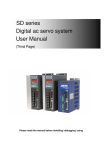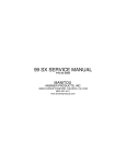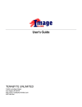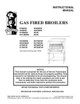
1
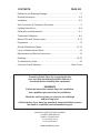
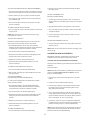
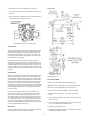
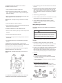
INSTALLATION • OPERATION MANUAL
for
COMSTOCK-CASTLE FOOD SERVICE EQUIPMENT
FOR YOUR SAFETY
Do not store or use gasoline or other flammable vapors or liquids
in the vicinity of this or any other appliance.
WARNING
Improper installation, adjustment, alteration, service, operation or
maintenance can cause property damage, injury or death. Read the
installation, operating and maintenance instructions thoroughly
before installing, operating or servicing this equipment.
NOTICE
Instructions must be posted in a prominent location that will provide
the user of this equipment with procedures, in the event he/she
smells and/or detects gas. This information must be obtained by
consulting the local gas utility.
READ CAREFULLY AND KEEP FOR FUTURE REFERENCE!
NOTE: The equipment for which this Installation • Operation Manual is provided may be certified,
have certification pending or not be certified under the standards of one or more of the following
organizations: Intertek Testing Services (ETL) Please refer to the chart on page 3 for the status of each
specific unit.
CONTENTS:
PAGE NO.
Definitions and Shipping Damage...............................................................3
General Information................................................................................ 3-4
Installation............................................................................................... 4-5
Gas Connection & Conversion Procedure..................................................5
Lighting Instructions................................................................................ 5-8
Calibration and Adjustments................................................................... 6-7
Thermostat Calibration............................................................................ 8-9
Manual Pilot and Thermocouple........................................................... 9-13
Preparation................................................................................................13
Griddle Plate/Broiler Option................................................................ 13-15
Lava or Radiant Broiler Option..................................................................15
Maintenance and Service Instructions......................................................15
Drawings............................................................................................. 16-33
Troubleshooting Chart...............................................................................34
Comstock-Castle Warranty........................................................ Back Cover
Comstock-Castle Stove Co. suggests that the
user read this Installation/Operation Manual in
its entirety before installing this equipment.
REMEMBER
Follow the instruction manual steps for installation.
Use a qualified gas technician for installation.
Check the unit every time you move for loose fittings
and for being level.
Call the factory if you have any questions about installation or need
the name of a qualified service/installation agent.
COMSTOCK-CASTLE STOVE COMPANY
119 WEST WASHINGTON
QUINCY, ILLINOIS 62301
217-223-5070 (Voice)
217-223-0007 (Fax)
www.castlestove.com
2. CONCEALED LOSS OR DAMAGE - If damage is unnoticed
until merchandise is unpacked, notify transportation company
or carrier immediately, and file a “concealed damage” claim with
them. This should be done within 15 days of the date delivery is
made to you. Be sure to retain container for inspection.
IN THE EVENT YOU SMELL GAS: Turn off gas supply. Open
Windows, Do Not Touch Electrical Switches, Extinguish All Open
Flame, and IMMEDIATELY CALL Your Gas Utility.
DEFINITIONS
QUALIFIED AND/OR AUTHORIZED OPERATING
PERSONNEL
Comstock-Castle cannot assume responsibility for damage or loss
incurred in transit. Comstock-Castle will, however, be glad to assist
you and furnish you with any necessary documentation to support
your claim.
Qualified or authorized operating personnel are those who have
carefully read this manual and are familiar with the functions of
the equipment. Those who have had previous experience with the
functions and operations of similar equipment should also read
this manual to acquaint themselves with the unique characteristics
of this equipment.
GENERAL INFORMATION
TO AVOID POSSIBLE INJURY, FIRE, and/or EXPLOSION, the
following precautions must be read, understood, and followed
explicitly.
QUALIFIED INSTALLATION OR SERVICE PERSONNEL
Qualified Installation and/or Service Personnel are defined as
those who, either in person or through a representative, are
engaged in and are responsible for:
CERTIFICATION STATUS * MINIMUM CLEARANCE
Model
The installation or replacement of gas piping from the outside of
the meter, (or service regulator when a meter is not provided), and
the connection, installation, repair, or servicing of the equipment.
Qualified personnel must be experienced in such work, be
familiar with all precautions required, and be able to comply with
all requirements of state or local authorities having jurisdiction.
Reference: National Fuel Gas Code ANSI Z223.1-latest edition
(NFPA Code 54).
Combustible
Back Side
OVENS &
RANGES
F3 Series
(ETL)
FK4 Series
(ETL)
P Series
(ETL)
B Series
(ETL)
SHIPPING DAMAGE CLAIM PROCEDURE
UNPACKING:
HOT PLATES
FHP Series (ETL)
SUFHP Series (ETL)
KFHP Series (ETL)
CSP Series (ETL)
SP Series
(ETL)
Inspect the crating for posible damage. Carefully remove the
gas appliance from the crate and inspect the unit for concealed
damage. (Preform applicable steps.)
1. Remove top grates and the range griddle plate if applicable.
2. Open oven door, remove rack(s), and oven bottom.
3. All packing material and burner tie down wire, if applicable, must
be removed.
4. If stainless steel, remove the protective covering.
GRIDDLES
FHP Series (ETL)
10 Series
(ETL)
9 Series
5. Properly install the legs or casters on the range.
NOTE: For proper operation and combustion, the legs or casters
MUST be installed. 10 series, 11 series, & CFHP FHP1-2-3-4.
SUFHP counter units do not have legs.
6. Locate the oven door handle and associated screws. Before
mounting handle, clear the insulation around the mounting
holes on the oven door. Using the two screws, mount handle to
oven door.
BROILERS
FHP Series
(ETL)
9 Series
(ETL)
Upon receipt and during installation of your new Comstock-Castle
equipment, inspect it thoroughly for damage that may have
incurred during shipment. If damage is evident, contact the carrier
immediately.
2”
2”
6”
6”
6”
6”
Non-combustible
Back Side
0”
0”
0”
0”
6”
0”
0”
6”
0”
0”
5”
4”
0”
0”
6”
6”
2”
2”
6”
6”
2”
2”
6”
6”
4”
0”
6”
6”
4”
0”
5”
4”
0”
0”
6”
6”
0”
0”
6”
6”
0”
0”
5”
4”
0”
0”
6”
6”
0”
0”
6”
6”
6”
2”
6”
6”
6”
2”
6”
6”
6”
2”
6”
6”
6”
2”
NOTE: FILE CLAIM FOR DAMAGES IMMEDIATELY, regardless
of the extent of the damage. Time limits are in effect.
FRYERS
2932SF
(ETL)
J01HG
(ETL)
2616HG
(ETL)
H Series
1. VISIBLE LOSS OR DAMAGE - Be certain this is noted on the
freight bill or express receipt and signed by the person making
the delivery.
All F3 and FK4 Series Ranges of this series are suitable for
installation on combustible floors. Counter equipment is for use on
non-combustible counters.
FOR YOUR PROTECTION, IF SHIPMENT ARRIVES DAMAGED:
3
NOTE: The Model No. KFHP Series Hot Plates are not ETL
Certified Designs.
INSTALLATION
THIS APPLIANCE IS INTENDED FOR OTHER THAN
HOUSEHOLD USE
All FHP Series, STFHP Series, and KFHP Series Hot Plates
are for use in combustible and non-combustible locations when
installed on a non-combustible counter.
All Comstock-Castle commerical gas appliances are manufactured by skilled craftsman using the finest quality materials.
PROPER installation by qualified personnel is essential for safe,
efficient, and trouble-free operation of the unit. Any alteration
and/or tampering, without proper knowledge, tools, and test
equipment, is DANGEROUS and will void all warranties.
The BTU input rating on all equipment is calibrated for elevations
up to 2,000 feet above sea level. All orifice drill sizes are
referenced for operation at or below this altitude. For operation
at elevations above 2,000 feet, the BTU rating must be reduced
4% for each 1,000 feet of elevation or the orifice drill size must be
changed appropriately. For high altitude drill sizes, call your local
gas company or Factory Authorized Service Center.
The installation must conform with local codes, or in the absence
of locel codes, with the National Fuel Gas Code, ANSIZ223.1
- latest edition.
All units are equipped with fixed orifices and cannot be adjusted.
If converting the gas appliance from natural to propane, or vice
versa, all orifices and the regulator must be changed. The correct
type of gas, for which the unit is configured, is noted on the
name plate. The type of gas specified MUST be used. For proper
conversion, contact a qualified service technician or your Factory
Authorized Service Center.
PRESSURE TESTING:
FAILURE TO INSTALL PRESSURE REGULATOR WILL VOID
WARRANTY. (Most units have a convertible regulator.)
The appliance and its indivdual shut-off valve must be disconnected from the gas supply piping system during any
pressure testing of that system at test pressure in excess of
1/2 psig (3.45 kPa).
When installed with casters, adequate means of restraint must
be provided to limit the movement of the appliance without
depending on the connector and the quick disconnect device or its
associated piping to limit the units movement. The restraint should
be securely fastened to the back of the unit. If disconnection of
the restraint is necessary, the restraint must be reconnected after
the appliance has been returned to its original installation position.
The appliance must be isolated from the gas supply piping
system by closing its individual manual shut-off valve during
any pressure testing of the gas supply piping system at test
pressures equal to or less than 1/2 psig (3.45 kPa).
NOTICE
For a gas appliance that is equipped with casters, the installation
shall be made with a connector that complies with the Standard
for Connectors for Moveable Gas Appliances, ANSI Z21.69 -1987,
and addenda Z21.69a -1989, and a quick disconnect device
the complies with the Standards for Quick Disconnect Devices
for Use With Gas Fuel, Z21.69 latest edition and Z21.41 - latest
edition.
The proper installation of this gas appliance is the total
responsibility of the end user.
It is the responsibility of the purchaser to determine that the
installer is qualified in installation procedures. Conversion,
connecting gas lines, calibrating thermostats, burners, lighters,
setting gas pressure with manometer, and etc., is all part of
normal installation and will not be paid for under warranty. If a
warranty technician is called out and finds the unit improperly
installed, the end user may be subject to billing.
Provisions shall be made in the design of the kitchen, to
ensure an adequate fresh air supply for proper ventilation and
combustion.
FOR MAINTENANCE, SERVICE, REPAIRS, OR
INSTALLATION - Contact your dealer or the factory, for your
local Factory Authorized Service Agency.
Do not obstruct the flow of combustion gases or ventilation air.
Never enclose the bottom of the unit with a raised curb and /or
any other construction that would obstruct the air flow into unit.
INSTALLING THE BACKSPLASH OR HIGH SHELF:
One of the most important considerations in the installation of this
unit is ventilation. A commerical gas appliance must be installed
so that the products of combustion are efficiently removed.
However, the kitchen ventilation system must not produce a draft
that would interfere with the proper operation of the burners.
To install a backsplash or high shelf on a Comstock-Castle Range,
proceed as follows:
1. Ensure back of unit is easily accessible.
2. If mounting low back (backsplash), slide into supports on back
of unit, and secure with #10 x 5/8” sheet metal screws.
The area around this and any other appliance must always
be kept free and clear of combustibles such as: grease, food
particles, fuel, solvents, cleaning fluids, gasoline, mops, rags, and
etc.
3. If mounting high shelf, mount shelf to high back using #24 x
3/4” machine screws with nut and washer.
During installation, use thread compound sparingly. Always
use a compound that is impervious to chemical reaction with
propane gases. NEVER put any of the compound on the first two
outer threads. This will minimize the possibility of the compound
breaking free and clogging the pilots, burner orifices, and controls.
4. Slide backsplash into the side-supports on back of unit, and
secure with #10 x 5/8” sheet metal screws. (Fig. 1)
When a commerical gas appliance is first installed, the gas
pressure must be checked with a manometer by a qualified
service technician. This will ensure that the existing gas facilities
will deliver the BTU’s of gas required on the rating plate.
WARNING - If the appliance in configured for LP Gas, never
connect the equipment directly to the pressure tank. Damage
will result to the appliance if the tank pressure is not properly
regulated. The regulator supplied with your unit is a low pressure
(1/2 PSI max.) appliance regulator. For proper pressure regulation
specifications, consult your local Factory Authorized Service
Agency or an LP Gas Distributor.
Figure 1
4
If a regulator has been shipped with the unit, it MUST be installed
properly. If not factory installed, connect regulator with arrow
pointing in the direction of gas flow. Use thread compound
sparingly. NOTE: DO NOT APPLY thread compound to the female
threads of any part.
HOOK-UP PROCEDURE FOR COMBINATION UNITS:
Units prefixed with a “2” may be shipped separately. For
connection, set the units side by side. Install backsplash. Install
hook-up strip in the front center of the two units. Ensure that
everything is aligned properly. Install and tighten all screws.
Some larger models may have two gas inputs for the manifold
system. If this is the case, all gas inputs to the unit MUST have a
factory approved regulator.
GRIDDLE PLATE INSTALLATION:
Griddle plate front trim must be placed under the plate rest
to prevent plate from moving. Rear of plate must be lifted to
allow front edge under the plate rest. If unit is equipped with
thermostat, sensing bulbs need to be installed under the
plate prior to placing front trim under plate rest.
IMPORTANT NOTICE FOR UNITS WITH
CONVERTIBLE PRESSURE REGULATORS
PROPANE GAS CONVERSION INSTRUCTIONS
GAS CONNECTION & CONVERSION
PROCEDURE
A griddle is equipped with fixed orifice hoods and shipped from
the factory for use on natural gas. To convert to propane gas,
install the propane burner orifice hoods supplied as follows:
GAS CONNECTION:
The size of the gas line is extremely important. If the
line is too small, the gas flow in the manifold will be low.
This inadequate flow will cause slow recovery and delayed
ignition. If in doubt about the proper size of your service line,
consult your local gas utility company.
1. Remove the griddle plate by lifting with two people and set
aside.
2. Slide the burners back off of the valve orifice hoods a couple of
inches and let it rest.
DO NOT connect appliance before testing the pressure of
the gas service supply piping system.
3. Remove the natural gas orifice hoods with a 1/2” wrench.
FOR NATURAL GAS - Fixed orifices are set at 4” W.C.
(water column). If a pressure regulator is supplied, it must be
installed when the unit is connected to the gas supply.
4. Apply a very little bit of pipe dope on the threads of the valve.
DO NOT APPLY PIPE DOPE INTO ORIFICE HOOD.
FOR PROPANE GAS - Fixed orifices are set at 10” W.C.
(water column). If a pressure regulator is supplied, it must be
installed when the unit is connected to the gas supply.
5. Attach the supplied propane burner orifice hoods with a 1/2”
wrench.
Pressure regulator must be tested in a full condition (all
valves “ON”). A condensation/paniculate trap must be provided in the supply line, with a separate shut-off valve upstream of the regulator. These items are customer installation
responsibilites.
6. Convert the pressure regulator from Natural to Propane gas by
inverting the snap-in device beneath the cap on the regulator.
This will require a fair amount of pressure. Do not remove the
spring. When replacing the cap make sure the snap-in insert
goes down on top of the middle of the spring. (Fig. 2)
Your Comstock-Castle appliance is equipped with a 3/4” NPT
entrance pipe. Level the appliance under station exhaust
hood and connect the gas line from the service gas shut-off
valve to the inlet side of the gas pressure regulator using 3/4”
pipe. DO NOT use a domestic type gas flexible connector. If
a flexible or semi-flexible connector is used, an AGA Certified
Flexible Connector with an inside dimension equal to 3/4” must be
used. Always aviod sharp bends that could restrict the gas flow to
the appliance. All piping must be installed in accordance with local
codes, or in the absence of
local codes, with the National Fuel Gas Codes: ANSI Z223.1
latest edition - NFPA No. 54.
7. Test for proper pressure; 10” W.C. (water column) using a
manometer.
8. Slide burners back onto the orifice hoods.
9. Apply the Propane “Notice” stickert to the front of the unit for
futer reference.
IMMEDIATELY CHECK the plumbing with a concentrated
soap solution or an approved gas dector. Coat all joints
associated with the gas distribution system. Bubbles indicate
leaks and the appliance MUST NOT be operated until the
leak is corrected. NEVER use an open flame to test for
leaks. Be sure to check all gas connections with the main
burner “ON” and “OFF”. Check and, if necessary, adjust the
manifold pressure.
GAS CONVERSION:
Figure 2
A qualified service technician must be used to safely
convert the appliance from natural gas to propane gas,
or vice versa. The regulator, burner orifices, pilot orifices,
and possibly the pilot lighter bar orifice, if applicable, must be
converted. The appliance must be retested for proper alignment, calibration, and gas pressure.
LIGHTING INSTRUCTIONS
NOTE: While lighting a manual pilot system, sufficient time
must be allowed for the proper pilot flame to heat the thermocouple that will hold the safety valve open. If lighting for the
first time, allow some time for air to be purged from the gas
distribution system.
Caution: Never attempt conversion when the unit is hot!
For all manually and thermostatically controlled equipment:
5
TO LIGHT THE CHINA HAT PILOTS: (OPEN TOP BURNERS)
2. Blow out pilot. The safety valve will automatically shut off the
gas supply system.
1. The main gas valve should be “OFF” for at least five minutes to
allow any accumulated gas to escape the combustion chamber.
TO LIGHT A STANDING PILOT:
(Manually Controlled Griddles)
2. Remove spider rings, open top grates, and locate the pilots.
3. Turn supply gas “ON” and hold match close to the pilot head.
The pilot should light.
1. The main gas control valve should be “OFF” for at least five
minutes to allow any accumlated gas to escape the combustion
chamber.
4. Turn the manual gas control to the “ON” position. The main
burners should light.
2. Sight pilot head through the pilot sight hole on front of apron.
TO TURN THE CHINA HAT PILOTS OFF:
1. Turn the supply gas control to the “OFF” position and ensure all
bunrers are off.
3. Turn on the main gas and hold a match close to the pilot head.
The pilot should light.
NOTE: Pilots cannot be shut off unless the main gas supply
to the appliance is shut off.
4. Turn the manual gas control to the “ON” position. The main
burners should light.
TO LIGHT THE OVEN PILOT:
TO TURN THE STANDING PILOT OFF:
Remove the lower kick panel below the oven door. Open oven
door and remove the oven rack. Remove oven bottom.
1. Turn the manual gas control to the “OFF” position and ensure
all burners are off.
1. The Robertshaw Grayson TS11J safety valve or BASO
H15HR-2 should be closed tor at least five minutes to allow any
accumlated gas to escape the combustion chamber.
NOTE: Pilots cannot be shut off unless the main gas supply to the
units is shut off.
2. Turn the thermostat to the lowest possible setting.
CALIBRATION AND ADJUSTMENTS
3. Depress and hold down the red button while lighting the pilot.
Hold the button down for about 45 seconds.
IMPORTANT: Calibration and adjustments are part of normal
installation and are NOT subject to billing under warranty.
4. Release the rest button. The pilot should stay lit.
TO CHECK AND ADJUST THE MANIFOLD PRESSURE:
5. Set the thermostat to the desired temperature. The main
burners should light.
All units must be tested for proper manifold pressure at the time of
installation.
TO TURN OFF THE OVEN PILOT: (See Fig. 3)
Proceed as follows:
1. Turn the thermostat to the lowest possible setting.
NOTE: MUST be performed ONLY by qualified service personnel.
Contact your Factory Authorized Service Agency. Call the
factory for the nearest agent.
2. Blow out pilot. The safety valve will automatically shut off the
gas supply system.
TO LIGHT THE GRIDDLE:
(Thermostatically Controlled Griddles)(0ptional)
1. Ensure the gas control and the main gas line is in the “OFF”
position.
For units that are equipped with a thermostatically controlled
griddle, proceed as follows:
2. Locate and remove the NPT pressure tap plug.
1. The Robertshaw Grayson TS1U and BASO H43A safety
valve should be closed for at least five minutes to allow any
accumulated gas to escape the combustion chamber.
3. Insert the proper fitting for a gas pressure measuring device
into the tap hole and connect the measuring device to the
fitting. (Manometer perferred).
2. Turn the thermostat to the lowest possible setting.
4. Turn on gas and light all burners. With all burners operating,
monitor the gas pressure reading for the correct pressure. For
proper and efficient operation, the pressure reading must be 4”
W.C. for natural gas; 10” W.C. for propane gas.
3. Depress and hold down the red button while lighting the pilot
through the pilot hole. Hold the button down for about 45
seconds.
4. Release the reset button. The pilot should stay lit.
5. If necessary, remove the cap on the regulator and adjust the
manifold pressure for the correct pressure as indicated on the
pressure measuring device on units with adjustable Reg.
5. Set the thermostat to the desired temperature. The main
burners should light.
NOTE: Turning the adjustment screw clockwise will increase the
output pressure and counterclockwise will decrease the output
pressure. Not all units have adjustable Reg.
TO TURN THE GRIDDLE OFF:
1. Turn the thermostat to the lowest possible setting.
6
6. ALWAYS ensure the cap is replaced on the regulator.
DIMENSIONS
7. Turn the gas and the unit “OFF” and reinstall the pressure tap
test plug.
8. Ensure the top of the regulator is kept clear of dust and fluids
as these will clog the regulator vent port.
Figure 3
Robertshaw Grayson TS11J Safety Valve
APPLICATION
The H43 valve is designed to provide safe lighting and complete
shutoff of pilot and main burner gas. An interlock between the
manual valve handle and the reset button allows gas flow only
to the pilot during pilot lighting. The control shuts off both main
and pilot gas if the pilot flame is extinguished. The manual valve
controls both main and pilot gas.
H43 valves are suitable for use with natural gas, Liquefied
Petroleum (LP) gas, and LP gas-air mixtures at pressures up to
35 mbar (0.5 psi). Models H43_A with a standard power unit are
suitable for operation over a temperature range of 0 to 80°C (32
to 175°F). Models H43_B with a high temperature power unit are
suitable for operation over a temperature range of 0 to 120°C (32
to 250°F).
DESCRIPTION
The H43 valve contains a plug valve with multiple drillings, which
allows it to serve as both the main burner valve and pilot valve.
The valve handle indicates the operating position. Safe lighting is
accomplished by a positive interlock between the valve handle
and reset button, which allows for resetting the valve to the pilot
position only. The handle incorporates a lock button to prevent
accidentally turning off the valve. The lock button must be lifted to
permit turning the plug valve to the Off position. The main burner
may be throttled between the On and Pilot position through the
use of the handle.
Dimensions, mm (in.)
PILOT ADJUSTMENT:
SAFETY PILOT ADJUSTMENT PROCEDURE: (Fig. 4)
NOTE: All Comstock-Castle appliances that are designed with
safety valves, are equipped with a pilot adjustment key.
For use with ovens and thermostatically controlled griddles:
In the event of pilot flame outage, gas is shut off both to the
main burner and pilot burner. The handle must be turned to the
Pilot position to reset the valve and light the pilot burner. The
pilot outlet is located on the right-hand side of the valve casting,
when looking into the inlet of the control with the reset button
up. The pilot connection is 1/4 cc. It flows toward the inlet of the
control and is regulated with a pilot adjustment screw. The pilot
connection is also available with the flow toward the outlet of the
control. (Contact BASO Gas Products.)
3. Turn the slotted pilot key to provide the proper size pilot. (See
Fig. 3, TS11J Safety Valve or BASO H43A).
MOUNTING
4. Replace the pilot adjustment cap.
H43 valves may be mounted in any convenient position with the
reset button and manual valve handle accessible.
5. If equipped with BASO H15HR-2 the pilot adjustment is made
with a fitting in the Back-out Pipe.
1. Remove knobs, control panel, oven rack(s), and the oven
bottom.
2. Locate the pilot adjustment screw cap on the safety valve and
remove the cap.
7
STANDING & CHINA HAT PILOT ADJUSTMENT
PROCEDURE: (Fig. 5)
1. Ensure the unit is shut off and cooled down.
2. Remove all knobs and the front apron panel from the unit.
NOTE: Caution must be exercised during the initial installation
and/or conversion of standing or china hat pilots to ensure that
the pilot valves are not wide open.
3. Loosen screw on the air mixer which is located on the venturi
section of the burner.
1. The main gas valve should be “OFF” for at least five minutes to
allow any accumlated gas to escape the combustion chamber.
4. Light the burner and set control for maximum “ON”.
Allow the burner to burn at least five minutes.
2. Gently remove the control knobs and the front apron panel to
the unit.
5. Open air mixer until flame starts to float fromt the main burner
ports.
3. Remove spider rings, open top grates, and locate the pilots.
6. Slowly close air mixer until the flame settles softly on the burner
ports. The flame should now be a well-defined blue with no
yellow tips.
4. Follow the pilot feed tube back to the manifold and locate the
pilot adjustment valve.
7. Carefully tighten the screw and ensure the flame has not
changed.
5. With a small flat-tipped screwdriver adjust the valve to its
minimum position, (maximum clockwise)
8. Replace apron and knobs, proceed to “THERMOSTAT
CALIBRATION”.
6. Ensure that the thermostat or manually operated controls are in
the “OFF” position.
THERMOSTAT CALIBRATION
7. Turn on the gas. While holding a match close to the pilot head,
slowly open the pilot valve (counter-clockwise) until the pilot
head lights.
NOTE: When Comstock-Castle griddles are equipped with a
Robertshaw thermostat, they are carefully calibrated at the
factory. If calibration is needed, it is recommended that ONLY a
qualified service techincian perform the adjustment.
8. Properly adjust pilot flame for the correct height.
(See Fig. 5)
NOTE: A properly adjusted pilot will NOT cause pilot/burner
infringement, flame lift, or excessive carbon.
BY-PASS ADJUSTMENT: (minimum burner flame)
When the cooking area reaches the temperature to which the
thermostat dial is set, the control will cut down the flow of gas
that is needed to keep is at the selected temperature. The control
must always by-pass enough gas to keep the entire burner lit.
The by-pass must always be carefully and accurately adjusted to
maintain the minimum flame.
9. Properly adjust all the pilot valves. Ensure all pilots will easily
ignite each burner.
10. Replace the front apron panel and knobs.
11. R
eplace top grates, spider rings, and proceed with
“BURNER ADJUSTMENT”.
NOTE: If the by-pass is in need of adjustment, it is recommended
the ONLY a qualified service technician perform the adjustment.
1. Light and adjust the pilot. Check and, if necessary, adjust the
manifold pressure.
2. Turn the dial completely “ON”, to light the burner.
3. Wait five minutes, turn and set the dial to a point slightly below
the first mark on the dial.
Figure 4
(Robertshaw 2C-1
4. Carefully remove the dial and the bezel.
Figure 5
(Pilot)
5. Locate the by-pass adjustment screw and monitor the burner
flame height. With a screwdriver, turn the by pass adjustment
screw counter-clockwise to increase the height of the flame and
clockwise to decrease the height of the flame. The adjustment
must maintain a minimum flame over the entire burner. The
minimum flame should be approximately 1/8” in height.
BURNER ADJUSTMENT:
(For oven, griddle, and open top burners)
NOTE: All Comstock-Castle appliances are equipped with fixed
orifices and the burners cannot be adjusted for gas flow. The
only adjustment necessary is the primary air adjustment. A
blue flame is necessary for proper combustion and maximum
efficiency. Check for proper operation after cleaning the unit. It is
recommended this adjustment be done at least once or twice a
year.
6. Replace the bezel and the dial, rotate the thermostat dial uniti it
locks in the “OFF” position.
8
THERMOSTAT CALIBRATION: (See Fig. 6)
6. While firmly holding the calibration stem in, turn the dial to the
actual temperature shown on the test instrument. Release the
pressure on the calibration stem and remove the screwdriver.
Replace the dial insert.
NOTE: Once the appliance is properly installed, all thermostats
associated with the equipment must be checked for proper
calibration. The thermostat is a precision instrument and is
carefully calibrated at the factory. Field calibration is seldom
needed and should not be attempted unless a considerable
amount of experience proves that the control is not maintaining
the dial set temperature. If calibration is needed, it is
recommended that ONLY a qualified service technician perform
the adjustment.
7. Set the temperature control dial to 400 degress. Once again,
check the temperature as instructed in steps 3 & 4. If the
temperature is not within 10 degress with a dial setting of
400 degress, then the sensing element is inoperative and the
control should be replaced.
Fryer Thermostat Calibration
NOTE: Always ensure the by-pass flame is properly adjusted prior
to any attempt to recalibrate.
1. Remove front cover of valve with Phillips screwdriver.
To check for proper temperature during test or recalibration,
always use an accurate test instrument with the proper sensing
device. This will ensure the correct temperature is being recorded.
On all griddle plates, use a disc probe and drop a few drops of
oil on the plate. Place the disc probe into the oil flat against the
griddles surface.
When placing the sensing probe in the oven, always ensure the
oven probe hangs freely approximately at the center of the oven.
Do not permit the probe to touch the sides or the racks of the
oven.
2. Remove knob by using flat screwdriver.
Figure 6
Robertshaw BJWA Thermostat
CALIBRATION STEPS:
1. Remove the thermostat dial and pull out the metal insert.
2. Replace the thermostat dial and set the dial to the 350 degree
mark. Light unit.
3. To increase temperature, turn brass knob counterclockwise.
Turn knob slowly until burner kicks on and wait for it to shut off,
check temperature, adjust until temperature reaches approx.
395 at #7.
3. Light oven and allow a sufficient amount of time for the
temperature to stablize (approximately 15 minutes).
4. Check temperature at five minute intervals uniti two successive
temperature readings are within 5 degrees of each other.
MANUAL PILOT SYSTEM
NOTE: If the control does not read within 10 degress of the dial
setting (350 degrees), the control should be recalibrated. For
recalibration proceed as follows:
When heat is applied to the thermocouple, a voltage is produced
that will energize the magnetic head in the safety valve. When
the pilot flame is extinguished, the voltage produced by the
thermocouple will decrease. Thus, both the pilot and the main gas
will be shut off at the safety valve.
5. Hold thermostat dial firmly, insert a screwdriver through the
center of the dial and push on the calibration stem. CAUTION:
DO NOT turn the stem.
9
TROUBLESHOOTING THE MANUAL PILOT SYSTEM
PROBLEM: (Pilot will not stay lit.)
1. Place the sensing probe of the test instrument in the middle of
the oven.
2. Light main burner and set the temperature dial to 400 degrees.
Allow the oven to heat until the burner flame cuts down to bypass. Check temperature on the test instrument. If temperature
does not read within 10 degrees of the dial setting, recalibrate
as follows:
1. Check for drafts that could blow out the pilots.
2. Ensure the pilot has a sharp blue flame. If not, clean pilot
orifice. CAUTION: Be careful not to enlarge or distort the pilot
orifice when cleaning.
3. Without turning, pull dial straight off.
3. Make sure thermocouple is properly seated in the safety valve
(finger tight plus 1/4” turn with a wrench).
4. Hold the calibration plate and loosen the calibration lock screws
until the plate can move independently of the control.
NOTE: DO NOT over-tighten, damage could result to the safety
valve.
5. Turn the calibration plate so that the reading on the test
instrument is in line with the indicator mark. Hold plate firmly
and tighten screws.
4. Check pilot adjustment, adjust if necessary.
Safety Warning Instructions
5. Have a qualified service technician properly test pilot system to
determine and correct the problem.
FOR MERTIK MAXITROL GV30 SERIES GAS COMBINATION
CONTROLS
TO REMOVE AND REPLACE THE THERMOCOUPLE:
! SPECIAL WARNINGS
1. Remove all items needed to gain easy access to the pilot head
assembly.
IF YOU DO NOT FOLLOW THESE INSTRUCTIONS
EXACTLY, A FIRE OR EXPLOSION MAY RESULT CAUSING
PROPERTY DAMAGE, PERSONAL INJURY OR LOSS OF LIFE.
NO UNTRAINED PERSON SHOULD ATTEMPT TO INSTALL,
MAINTAIN OR SERVICE GAS PRESSURE CONTROLS.
2. Unscrew thermocouple lead in pilot head.
3. Unscrew thermocouple lead from safety valve and remove the
thermocouple.
To minimize the possibility of FIRE, EXPLOSION, and OTHER
HAZARDS.
4. To replace the thermocouple - reverse the above procedure
and test.
1. All products, including gas pressure controls, used with
combustible instructions of the manufacturer, with government
codes and regulations, and plumbing codes and practices.
THERMOCOUPLE VOLTAGE RANGE: Comstock-Castle
equipment may be configured with the following. In the event of a
failure, replace with an identical component only!
2. Do not use a gas combination control if it appears to have been
subjected to high temperatures, damaged in any way, or to
have been taken apart or tampered with. Any of these may be
signs of possible potentially dangerous combustion problems.
Robertshaw thermocouple part #T46. Manufacturer suggested
operational voltage range, 18 to 24 milivolts.
NOTE: DO NOT over-tighten (finger tight plus 1/4” turn with a
wrench).
3. Installation
a. Turn off gas supply before starting installation.
b. Install the control properly so gas will flow as indicated by
the arrow on the casting.
c.Make sure markings or wording on control are not painted
over or obliterated.
Mounting positions (see diagrams below)
d. The gas control can be mounted horizontally 0 to 90
degrees in any direction from the upright position, i.e. from
the position when the knobs are on top. It can also be
mounted in a vertical position.
Figure 7
Robertshaw FD Thermostat
TO CALIBRATE THE ROBERTSHAW FDH, FDL, & FDO OVEN
THERMOSTAT FOR FRYERS, PIZZA AND BAKE OVENS:
10
Main gas NPT connections (inlet or outlet)
e. Use joint compound/thread
sealant, properly threaded
pipes and careful assembly
procedure so that there is
no cross threading, etc.,
which can cause damage or
leakage.
f. Apply light pressure only at
wrench flats (see Figure 1)
to avoid damage to control
body, which can result in
leakage or malfunction of
control. Do not apply pressure
to top casting or plastic cover.
4.Check carefully for gas leaks immediately after the control
has been installed and the gas turned on. Do this before
attempting to operate the appliance or other gas
burning device. Use a rich soap solution (or other accepted
leak tester) to check all flanges, knobs, joints, and piping
connections. Wipe clean with a damp rag. It is a good practice
to periodically check for leakage during use of the appliance.
Absolutely no leakage should occur, otherwise there is a
danger of fire or explosion depending upon conditions.
Never use if leakage is detected.
Main gas (outlet only)
and/or *side outlet tubing connection
g. Square off end of tubing and remove burrs.
h. Slip gland and ferrule over tubing.
I.Insert tubing into the outlet until it bottoms, slide ferrule
and gland into place and turn finger tight. Do not use joint
compound.
j.Use a wrench to tighten gland about one turn beyond finger
tight. (*if side outlet model, do not rotate outlet in its threads
to avoid possible leakage.)
Pilot gas connection (tubing only)
k. Square off the end of tubing and remove burrs.
l.Slip compression fitting over tubing. Insert tubing into pilot
outlet connection until it bottoms, slide fitting into place and
turn finger tight.
Do not use joint compound.
m.Use a wrench to tighten fitting about 1-1/2 turn beyond
finger tight.
n.Connect other end of tubing to pilot burner according to the
manufacturer’s instructions.
NEVER CONNECT CONTROL DIRECTLY TO THE
PROPANE SUPPLY SOURCE. LP APPLICATIONS
REQUIRE AN EXTERNAL REGULATOR (NOT SUPPLIED).
INSTALL THE EXTERNAL REGULATOR BETWEEN THE
PROPANE SUPPLY SOURCE AND
MERTIK MAXITROL CONTROL.
5.Adjustments and Final Checkout
!
Removing cover
a. Unscrew the cover at the side of the thermostat knob.
b.Put a small screw driver in the slotted hole at the side of
the operation knob and lift the cover.
Pilot flame adjustment
c. Combination control is shipped with pilot flow at maximum.
d.Refer to the pilot burner manufacturer’s instruction for
recommended size of pilot flame.
e.If adjustment is required, turn the pilot adjustment screw
clockwise to decrease or counterclockwise to increase pilot
flame.
CAUTION
DO NOT BEND TUBING AT GAS CONTROL AFTER
COMPRESSION FITTING HAS BEEN TIGHTENED,
AS THIS MAY RESULT IN GAS LEAKAGE
AT THE CONNECTION.
Thermocouple connection
o.The gas control has an electrical themocouple connection
and must therefore be kept clean and dry; joint compound
should never be applied to it. Tighten only 1/4 turn beyond
finger tight in order to make a good electrical connection.
When mounting the themocouple tubing, do not bend it too
sharply (min.radius 25 mm).
Bulb Location and Mounting
p.Temperature sensing element is to be located and mounted
by the OEM and is not to be changed without consulting
factory or qualified serviceman. The temperature sensing
element should be placed in a location representative of
desired temperature. Never place directly in flame.
11
WARNING
ADJUSTMENTS MUST BE MADE BY QUALIFIED
PERSONS ONLY. BEFORE ADJUSTMENTS CAN BE
MADE, THE COVER SHOULD BE REMOVED.
IF THE APPLIANCE MANUFACTURER SUPPLIES
CHECKOUT AND/OR SERVICE AND MAINTENANCE
INSTRUCTIONS, CAREFULLY FOLLOW THEM.
IF THESE INSTRUCTIONS ARE NOT PROVIDED THEN
USE THE FOLLOWING PROCEDURE.
!
CAUTION
!
Figure 1
Outlet pressure adjustment (a gauge capable of reading
inches w.c. is required for any outlet pressure adjustments)
f.Remove cover to expose pressure regulator adjustment
screw.
g. Bring unit to high fire (all burners on maximum).
Slowly turn adjustment screw with a small screwdriver until
the required burner pressure is recorded on the pressure
gauge. Turn adjustment screw clockwise to increase or
counterclockwise to decrease gas pressure to main burner.
*Side-outlet manual valve minimum flow adjustment
h.Combination control is shipped
with the side-outlet manual
valve set at maximum flow. If
adjustment is required perform
step g., and then set the manual
valve knob (knob-C, Figure 2) to
the minimum positon.
Turn side-outlet manual valve
minimum adjustment screw
(Figure 2) clockwise to decrease
flow.
Figure 2
(Shown with cover)
( *Do not rotate side outlet in its threads to avoid possible
leakage.)
i.Replace cover.
7. V
ery high pressure surges in the gas supply line (or as a result
of exposing the system to high pressure) may result in serious
internal damage and cause leakage or affect control operation.
If you suspect tht a Mertik Maxitrol control has been exposed to
more than 1-1/2 times its maximum inlet pressure, turn off the
gas and have the system checked by an expert.
Final checkout of the installation
After any adjustment, set appliance in operation. Observe
several complete cycles to ensure that all burner components
function correctly.
6. Operation
Basic opertation
Knob-A (Figure 3) for manual pilot,
on-off function, and piezo activation.
Knob-B (Figure 3) for temperature
level selection with intergrated
thermostat providing snap action(onoff) and modulation control for
minimum to maximum flow.
8.The outlet pressure of the control must be measured to make
sure it is in accordace with intended usage.
9.Caution should be used to guarantee that there is sufficient
inlet pressure to achieve the desired outlet pressure and no
readjustment of the outlet pressure setting should be made
unless the inlet pressure is within the proper limits for the
control. Failure to follow this may result in overfiring of the
appliance or other gas burning device.
Figure 3
(Shown with cover)
10.A Mertik Maxitrol combination control must be used within its
ambient temperature range, and not in excess of its maximum
inlet pressure. The control can be used with all fuel gases.
Ignition intrlock
The interlock device prevents the
re-establishment of gas flow – when
no pilot flame is present – until the thermocouple has cooled
sufficiently.
11.In case of any doubt, please contact the Service Manager,
Maxitrol Company, Southfield, MI. Phone: 248/356-1400.
12.Specifications
Maximum Operating Inlet Pressure
1/2 psig (34.5 mbar)
Adjusting temperature
Turn knob-B (Figure 3) toward higher numbers to increase
temperature, toward lower numbers to decrease. Remote
control versions contain a motor that activates this knob, or it
can also be operated manually.
Ambient Temperature (Control)
32° to 176° F (0 to 80° C), or 32° to 225° F (0° to 107° C) for
“T” Models
Control Range
Capacity:
10,000 – 85,000 BTU/hr
Outlet Pressure: 3” w.c. to 5” w.c. (7.5 to 12 mbar)
8” w.c. to 12” w.c. (20 to 30 mbar)
*Piezo & Cable
Min/Max Spark Gap: 3/4 mm
Min/Max Operating Temperature: -4° to 392° F (-20° to 200° C)
Min/Max Lead Lenghs: 150/1000 mm
(*Piezo wire should not be drawn down parallel against
lengths of metal –this can result in reduction or loss of power
to ignitor. When placing the ignition cable/piezo wire, care
should be taken not to stretch it too tightly. If possible, avoid
contact with the appliances’s metal parts, especially those with
sharp edges.)
Optional side-outlet control for 2-burner operation
Additonal side-mounted manual valve (knob-C, Figure 3)
primarily for 2-burner gas fireplace applications.
Lighting procedure
a.Turn knob-A (Figure 4) slightly
left towards the ‘IGN’ position
until reaching stop, press down
and hold for five seconds (only
pilot gas flows).
b.Continue pressing down while
turning further left to activate
piezo, continue to hold down for
10 seconds after pilot burner
has been lit. If pilot does not
light, steps a. and b. can be
immediately repeated. (See Note below)
Figure 4
c.Upon lighting, release knob and turn further left to ‘ON’
position (both pilot and main gas flows).
Note: If pilot flame is not established, equipment manufacturer
(OEM) will determine the number of additonal attempts to light
– and with continued failure the purge time.
Shut off procedure
a. Turn knob-A (Figure 4) right until reaching stop.
b.Press down slightly and continue turning right from ‘PILOT’
position to the ‘OFF’ position.
When the thermocoupler has cooled sufficiently (time will vary
based on themocouple type used), pilot lighting procedure can
be repeated. (See Ignition interlock.)
Maximum Ambient Temperature (Sensor)
Control Range 55° – 95° F: Sensor 122° F ( 50° C)
Control Range 60° – 120° F: Sensor 160° F ( 71° C)
Control Range 85° – 175° F: Sensor 230° F (110° C)
Control Range 210° – 640° F: Sensor 715° F (380° C)
Hardwired Wall Switch
Use 24 gauge wire or larger for a maximum run of 100 feet
Ultrasonic Remote Control and Receiver
Receiver wire to combination control is rated at 350° F
Optimal remote operating distance 20 feet
(For best results use fully charged ALKALINE batteries in
ambient temperatures less than 125° F)
12
!
4. Light burners. Adjust the flame to the lowest setting possible.
Maintain a low flame setting for one hour.
WARNING
USE CAUTION WHEN LEAVING AN OPERATING
5. Allow the plate to cool, then wipe off residue with a clean cloth.
MOTORIZED CONTROL UNATTENDED.
ALTHOUGH UNLIKELY, RANDOM SONIC SOUNDS
GRIDDLE OPERATING SUGGESTIONS & CAUTIONS:
COULD SIGNAL THE ULTRASONIC RECEIVER AND
• A
lways allow sufficient time to ensure that the temperature
of the plate is up to the desired temperature before using.
ACTIVATE THE VALVE — LOWER KNOB ‘B’ COULD
ROTATE AND CAUSE THE MAIN BURNER TO COME ON,
OR THE FLAME HEIGHT TO ADJUST.
• N
EVER over heat the griddle plate and always reduce the
temperature during idle periods.
PREPARATION
• A
lways clean griddle plate after use and coat plate with a
light coat of cooking oil.
Transite Stone Break-In Procedure:
If the oven is configured as a Pizza Oven, the racks used are
called transite stones. These stones will naturally draw moisture,
and will crack if not properly treated.
• F
or cleaning, griddle pads and griddle bricks may be used
on steel plates ONLY.
• A
s a sanitary and safety precaution, always keep the
grease drawer clean and empty.
WARNING: DO NOT clean stones with high abrasion brushing or
water as they may crack! Liquids should NEVER come in contact
with the stones! Wipe clean with a dry rag!
• If griddle plate is placed in storage, cover and store in a
dry location. If stored for any length of time, saturate plate
with a coat of lard to prevent rusting.
INSTALLING THE TRANSITE SHELVES:
1. Once the oven has been properly installed, slide the stone into
the guide.
OPEN TOP BURNER OPERATION:
9 & 10-11 SERIES (Non-Certified Equipment)
2. To minimize warpage and maximize the life of the stones, it is
strongly recommended that they be predried. First, preheat the
stones with the pilot burner on for one hour. Then over a five
hour period gradually increase the temperature 100 degrees
an hour to achieve baking temperature, then allow one hour to
elapse to complete the procedure.
If your new Comstock-Castle Counter Griddle contains an open
top burner section, the unit is referred to as a “Combination
Griddle”. This unit will be configured with a cast iron burner base
that incorporates a stainless steel or aluminum burner ring.
FOR PROCEDURES REFERENCE THESE SECTIONS:
3. A slight odor and outgassing may occur during the initial
heat up. This is normal as the stones are adjusting to their
environment.
• STANDING PILOT LIGHTING
• STANDING PILOT ADJUSTMENT
• BURNER ADJUSTMENT
4. The stones should be reversed periodically to equalize wear.
BROILER OPERATION - 9 & 10-11 SERIES (Non-Certified)
5. D
O NOT wedge stones together! The stones must be installed
un-restrained with approximately 1/8” joint space for every 24”
of deck to allow for expansion. Mechanically fastened stones or
those installed tightly are subject to cracking!
If your new Comstock-Castle Counter Griddle contains a Broiler/
Griddle combination, the unit is referred to as a “Combination
Griddle”. This appliance is identified by the letter “B” following the
model number. Unlike the standard griddle model, this unit will be
equipped with one or more burners fitted with a specially designed
flame spreader. This flame spreader directs heat down for broiling
purposes.
GRIDDLE PLATE/BROILER OPTION
BREAK-IN PROCEDURE:
MANUALLY OPERATED BROILER/GRIDDLE:
IMPORTANT: A rust inhibitor has been coated on the griddle
surface to protect it during shipment and storage. This rust
inhibitor MUST be removed front the griddle plate prior to placing
the unit in service.
When broiling is desired, turn the manual control completely
counter-clockwise for initial power up. Always reduce the setting,
to a lower operating temperature after the initial high heat setting.
Operating the unit at this high heat setting for longer than 15
minutes could discolor the griddle top.
1. Wash thoroughly with a mild detergent and rinse with ample
clean water.
Always remember when heat is applied to the broiler, heat is
also being applied to the griddle plate.
2. Thoroughly dry the griddle plate with a soft rag, then place it
securely on the body, with front of trough under plate rest on F
Series.
ALL BROILER VALVES WILL NEED TO BE REGREASED
DUE TO HIGH OPERATING TEMPERATURES.
3. Cover plate with table salt and satuate with cooking oil.
13
There are many other factors to keep in mind, more so in a
mobile operation. Many people think they do not need a pressure
regulator on the appliance as well as on the tank. This is not
true! There should always be a tank regulator on the tank and
an appliance regulator on each gas appliance due to each
appliance’s distinctive operation pressure. Giving an appliance
too much or too little gas pressure can cause operation and
performance problems.
FRYER LIGHTING INSTRUCTIONS
When installing, you should use a manometer to check and set
the appliance to the designed operation pressure. Model 2923SF,
2932SF, 2941SF is designed to operate at ten (10) inches water
column (WC) for LP gas. Make sure you fill the tank with oil or
water whenever you run the burners. four (4) inches water column
when operation on natural gas.
For adjustments, if needed, follow instructions 1 and 2 .
NOTICE:When turning on the gas at the propane tank, turn gas
on very slowly. Turn valve just a small amount. This
allows the gas to get into the lines without shutting the
tank regulator down. The regulator on the tank should
have a safety feature that is designed to sense a leak.
After lighting pilot, open tank valve a few turns.
1. Pilot Flame Adjustment
Combination control is shipped with pilot flow at maximum. Refer
to the pilot burner manufacturer’s instruction for recommended
size of the pilot flame. If adjustment is required, turn the pilot
adjustment screw clockwise to decrease or counterclockwise to
increase pilot flame.
1. Turn knob to pilot position.
2. Outlet Pressure Adjustment (a gauge capable of reading
inches W.C. is required for any Outlet Pressure Adjustments)
2. Push knob in.
3. Light pilot while holding knob in.
Remove cover to expose pressure regulator adjustment screw.
Bring heater to high fire (all burners on maximum). Slowly turn
adjustment screw with a small screwdriver until the required
burner pressure is recorded on the pressure gauge. Turn
adjustment screw clockwise to increase or counterclockwise to
decrease gas pressure to main burner.
4. Hold knob in for 30-60 seconds while thermocouple heats up.
(May take longer at initial set up to purge lines.)
5. Release knob, check to see if pilot stays on.
6. Turn knob to ON position.
APPROXIMATE TEMPERATURE FOR KNOB SETTINGS
#1Setting
240
#2
260
#3
286
#4
315
#5
335
#6
361
#7
397
Once you have set the unit at 10 inches W.C., turn off all the
appliances and shut off the gas supply. Remove the manometer.
When you install the pressure regulator, it is preferable to use
pipe sealer on the threads. Do not get sealer on the last few
threads. This keeps the sealer from drying, then breaking off
inside the pipe and plugging fittings and controls.
Whenever the equipment is moved or shut down, make sure you
follow the lighting instructions. If the thermostat or regulator is
struck, they may be knocked out of adjustment and need to be
recalibrated.
SPECIAL INSTRUCTIONS FOR SHALLOW FRYER
In a mobile operation, please keep in mind that every time the unit
is moved, you should check the pilot and, of particular importance,
check that the unit is as level as possible. If you are in a trailer,
perhaps you can make adjustments to the trailer for each site.
The legs on the 2323SF, 2932SF, 2941SF have adjustable feet
and can be used to level the unit. You want the unit to be slightly
higher in the back than in the front. This allows combustion air to
more easily be drawn in the front and exhausted by the rear flue.
If the unit is out of level with the front higher than the back, the
combustion may flue out the front and destroy the safety valve
and makes for less operator comfort.
Comstock-Castle’s model 2923SF, 2932SF and 2941SF is
designed as a shallow, large surface area fryer. This fryer is
designed for use in permanent locations operating on natural or
LP gas.
Model 2923SF, 2932SF and 2941SF can be used in mobile
operations, but, due to the nature of these types of operations,
special consideration should be given. Please follow the
installation manual supplied. if you have any installation questions
at all, please call us at 217-223-5070. Follow the pilot lighting and
thermostat calibration instructions in the manual. Many people
think they can successfully install gas appliances because they
have a pipe wrench and make a leak-free connection - this is not
the case.
Do not place a fan so the air blows directly at the front of the unit
or down the flue. Also, avoid locations that have natural draft
blowing into the unit or down the flue. These drafts will cause pilot
14
problems and when the pilot goes out, The entire unit shuts down
and must be relit. Never place anything on top of the flue!! the
2923SF, 2932SF, 2941SF is designed to operate with the front
door in place. The front door is removeable for cleaning, servicing
and draining, but should be kept on during operation.
TO CLEAN THE OVEN/BROILER INTERIOR:
1. Allow the oven/broiler interior to cool, completely. Use
a nonalkaline based cleaning agent, following the
recommendations of the manufacturer. DO NOT use abrasives.
Oven cleaner may be used on surfaces which have procelain
enameling.
Keep the interior of the unit as clean as possible. Keeping the
controls and burners clean and free of grease will allow them to
burn clean and perform as required.
2. Rinse thoroughly with cool, clean water. Dry thoroughly. Clean
daily or as needed.
LAVA OR RADIANT BROILER OPTION
3. Should the pilot be extinguished, follow the Lighting
Instructions.
During initial installation, cover the bottom of the broiler firebox
with one or two layers of volcanic rock. For cooking, turn the
valves full on and preheat the unit for about 15 minutes. Then
adjust the burner flame height as desired for broiling. Broiling
with volcanic rock is like broiling with charcoal. Various meat
densities and sizes will require different temperature settings and
cooking times. This can be affected by adjusting the valves. Install
radiants with smaller on outside of firebox, than large-smalllarge...across width of firebox.
To reduce down time and for maximum efficiency, have your
appliance serviced once or twice a year, depending on the
amount of usage. Have a technician:
• Examine the appliance venting system at least twice a year.
• C
lean and adjust burners, lighters, regulators, and etc. twice
a year.
Residual grease on the radiant grates and/or volcanic rock
should be burned off after use or prior to next use. Turn the
valves on full for 15 minutes or until all the grease is burned off
from the previous broiling. Never cover top grate with pans when
heating.
heck and calibrate the thermostats and the manifold
• C
pressure at least once a year.
• R
egrease manual control valves. Call factory for service
bulletin.
MAINTENANCE AND SERVICE INSTRUCTIONS
Like any other piece of equipment, the unit must be cleaned
on a regular basis.
CAUTION: FOR YOUR PROTECTION: This is commerical
cooking equipment. If should be kept in mind that when
in operation, the surface temperature will exceed that of
equipment designed for household use. Always maintain the
proper clearance as specified in the table cited under General
Information.
If the unit is restrained, the operator should be aware of how the
unit is restained. The operator should be familiar with how to
connect and disconnect the restraints. If the restraint is removed
for service or maintenance, the restraint must be reconnected
prior to putting the unit back into service.
NEVER attempt to move or slide the unit when hot.
ALWAYS let the unit cool down and empty the grease drawer
prior to any attempt to relocate or move the unit. NEVER move or
transport the unit when the unit is hot.
TO CLEAN THE EXTERIOR: (Stainless Steel)
1. Let it cool down. Normal daily soil can be removed with a mild
detergent or soap solution applied with a damp cloth. Rinse
and dry thoroughly.
2. To remove baked-on grease, apply a cleanser in the direction
of the polish lines on the metal. NEVER rub in a circular motion.
Scotch Brite or Stainless Steel scouring pads may be used on
tough or burnt-on deposits that do not respond to the procedure
above.
15
16
17
18
19
20
21
22
23
24
25
26
27
28
29
30
31
32
33
TROUBLESHOOTING CHART
PROBLEM
PROBABLE CAUSE
POSSIBLE SOLUTION
1. Appliance will not ignite.
1a. No gas.
1b. Air in gas line.
1c. Improper gas line supply.
1d. Gas turned on too fast at tank.
1a. Ensure gas is turned on.
1b. Purge air from gas line.
1c. Ensure piping will supply adequate pressure.
1d. Turn on at tank very slowly.
2. Pilots will not light.
2a. Pilot valve is shut off.
2b. Fans or air drafts interfering with pilot
operation.
2c. Improper pilot adustment.
2d. Bad or weak thermocouple.
2e. Bad or weak electromechanical head in safety
valve.
2a. Locate and adjust pilot.
2b. Locate and eliminate air drafts.
2c. Locate and adjust pilot.
2d. Have a technician properly test the
thermocouple.
2e. Test safety valve with a turn down test.
3. Y
ellow flame or yellow tipped flame on
burners.
3a. Lack of primary air supply.
3b. Improper pressure.
3a. Thoroughly clean and/or adjust air mixer.
3b. Check and adjust manifold pressure.
• Check orifice drill siae.
• E
nsure gas stream enters center of
mixing tube.
• Check mixing tube for obstructions.
4. Orange flame.
4a. Dirt and /ordust are being carried through
burner ports.
4a. Clean inside burner and burner ports with
small brush and blow out burner with air.
(correction needed only in exceptional cases.)
5. Flame lifts above burner ports.
5a. Too much primary air.
5b. Improper manifold pressure.
5a. Reduce the amount of primary air.
5b. Check and adjust manifold pressure.
• Check for proper orifice drill size.
5c. Lift back of plate with adjusting screws 1/8”.
6. Delayed ignition or slow lighting.
6a. Improper manifold pressure.
6b. Pilot flame improperly located.
6c. Too much primary air.
6a. Check and adjust manifold pressure.
6b. Properly adjust and locate pilot assembly.
6c. Adjust primary air.
7. Odor: gas/combustion.
7a. Gas odor: leak in appliance.
7b. Combustion odor: lack of secondary air..
7a. Check appliance thoroughly for gas leaks with
soap solution - bubbles.
7b. Ensure air and flue passages are clean.
8. Floating flame.
8a. Lack of secondary air.
8a. Check secondary air vent passages for
obstruction. Check for adequate air intake to
combustion chamber.
8b. Lift back of plate with adjusting screws 1/8”.
9. Noise:
9a. Explosion inside burner when flame is
shut off.
9b. Noise in air mixer and mixing tube.
9c. Whistling noise in orifice.
9a. Burner head too hot.
9b. Flame inside burner.
9c. Faulty adjustment - seating.
9a. Check manifold pressure
and adjust if necessary.
• Check for proper orifice size.
9b. Obstruction in orifice - clean or replace orifice
hood.
9c. Make sure orifice is tight. Replace orifice hood,
if necessary, making sure orifice is properly
drilled.
10. Uneven or improper heating on griddle plate.
10a. Thermostat improperly adjusted.
10b. Improper orifice size.
10c. Improper griddle plate temperature.
10d. Misaligned by-pass adjustment.
10e. Bad thermostat.
10a. Check and adjust manifold pressure and
primary air to burner.
10b. Check orifice size.
10c. Check and properly calibrate thermostat.
10d. Check and, if necessary, adjust the by-pass on
thermostat.
10e. Check thermostat for proper seating against
bottom of plate.
10f. Replace thermostat.
11. Valve hard to turn.
11a. Valve grease drying out internally.
11a. Periodic maintenance with hi-temperature
valve grease.
CALL FOR SERVICE BULLETIN
CALL FOR SERVICE BULLETIN
If problems arise during warranty time period, please call factory for authorized service agency.
Manufacturing drawings of parts and manifolds are available from the factory. Please call if needed.
34
COMSTOCK-CASTLE WARRANTY
Comstock-Castle Stove Co. (hereinafter Factory), warrants its new product(s) to be free from defects in material
and workmanship under normal use for a period of one (1) year from the date of original installation, not to exceed
eighteen (18) months after shipment from Factory or Factory facility. Factory warranty covers the contiguous
United States. Alaska, and Hawaii for both parts and labor. This warranty is extended to the original commerical
user and is not transferable. Initial installation, including calibration, is considered to be a customer responsibility.
The initial installation must be accomplished by an authorized service technician or a licensed plumber who
is familiar with gas and combustion systems, or this warranty will be considered to be void. Reasonable
service/labor costs, as defined by the factory, will be paid for a period not exceeding 90 days from the date of
installation/calibration. Original parts will be replaced for one year from the date of initial installation, upon return
(at customer’s expense) of the defective part, at no charge to the customer for the part or outbound shipping.
Expenses for shipping of parts requested by 2nd day or next day service will be at customer’s expense.
PROVISIONS:
A) Proof of installation date MUST BE SUBMITTED on the factory supplied Warranty Registration/
Installation Checklist prior to work being performed.
B) Such repair shall be performed within fifty (50) miles from an office of a Factory Authorized Service Agency
or sub-agent or any other licensed agent approved in writing by factory.
C) The equipment has not been damaged, altered, or misused.
D) The equipment is properly installed, adjusted, operated, and maintained in accordance with national, state,
and local codes for commerical kitchens and in accordance with the installation instructions provided with this
product.
E) The warranty serial number plaque affixed to the appliance has not been defaced, obliterated, or removed.
F) An acceptable report for any claim under this warranty shall be supplied to Factory within (30) days of the work
performed.
G) Comstock-Castle shall not be liable, whether in contract or in tort, or under any other legal theory, for loss of
use, revenue or profit, or for substitute use of performance, for incidental, indirect, or special, or consequential
damages, or for any other loss of cost of similar type.
EXCLUSIONS:
A) Factory shall have no obligation as to any product(s) which have been misapplied, mishandled, abused,
misused, subjected to harsh chemical action, or poor water/gas quality, modified without written approval from
the factory, damaged by flood, fire, or other acts of nature.
B) Re-calibrations associated with the replacement of a defective part otherwise covered under this warranty for
labor will be covered to the extent of one (1) service call (i.e. the call during which the part is replaced).
C) Factory assumes no responsibility for travel costs beyond 100 miles round trip. travel other than overland and
overtime costs of repair.
D) Factory excludes paint and procelain finish, gasket material, ceramic material from normal coverage.
E) Factory liability on a claim of warranty shall not exceed the price of the material and/or service which caused
the claim.
F) This warranty is limited and is lieu of all other warranties, expressed, or implied. Factory employees or agents
shall not be held liable for any claims of personal injury, or consequential damage or loss.
G) Factory assumes no responsibility for installation, adjustments, diagnosis, or normal maintenance such as
lubrication of springs or valves.
SUBSTITUTIONS:
In line with our policy to continually improve our product, Comstock-Castle reserves the right to change materials
and specifications without notice.
RETURN:
Return allowed within 90 days of invoice date, with prior written authorization from the factory, shipped freight
prepaid. Equipment must be unused and in packaging acceptable for a damage free return. A 20% restocking
charge is assessable.
Revision Date: 9-07 mcd
Supersedes All Previous Manuals.
Printed in the U.S.A.