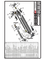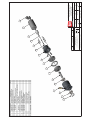
1
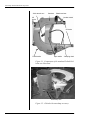
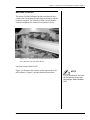
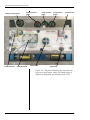
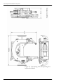
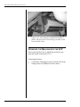
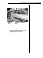
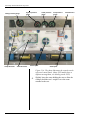
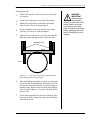
Autoclamp Goliath Guillotine
Pipe Saw
User’s Manual
Wachs Subsea
15331 Vantage Parkway East
Houston, TX 77032
www.ehwachs.com
Wachs Subsea Part No. 06-150-520-MAN
Rev. 3-1014, October 2014
Revision History:
Original
June 2007
Revision 1
July 2010
Revision 2
September 2010
Copyright © 2014 Wachs Subsea. All rights reserved.
This manual may not be reproduced in whole or in part
without the written consent of Wachs Subsea.
EU DECLARATION OF CONFORMITY
WITH
COUNCIL DIRECTIVE 2006/42/EC
Issue Details:
Directives:
Conforming Machinery:
Model Number:
Date:
Place:
9/19/2014
E.H. Wachs, Lincolnshire, IL USA
Machinery Safety Directive 2006/42/EC
Goliath Saw
Topside Control Unit
P06-150-520
H10-023-000
Serial Number:
Manufacturer:
E.H. Wachs Company
600 Knightsbridge Parkway
Lincolnshire
IL 60069
USA
Responsible Representative: Orbitalum Tools GmbH
Josef-Schüttler-Str. 17, 78224 Singen
Germany
Tel. +49 (0) 7731 - 792 872
Fax +49 (0) 7731 - 792 566
Harmonised Standards & EN ISO 12100:2010, EN ISO 13849-1-2, EN ISO 61310-1Other
Technical 2:2008, EN ISO 4413:2010, ISO 6149-1-2-3, ISO 11688-1,
Standards/Specifications
ISO 19902
Applied or Referenced:
Essential Health and Safety Requirements of Annex 1 of the
Provisions with which
Conformity is Declared:
Machinery Directive
We hereby certify that the machinery described above conforms to the provisions of
Council Directive 2006/42/EC on the approximation of the laws of the Member States
relating to the safety of machinery.
Signed:
Signatory:
Pete Mullally
Quality Manager
E.H. Wachs
Table of Contents
Chapter 1: About This Manual . . . . . . . . . . . . . . . . . . . . . . . . . . . . . . . . . . . . . . . . . 1
Purpose of This Manual . . . . . . . . . . . . . . . . . . . . . . . . . . . . . . . . . . . . . . . . . . . . . . . . . . . . . . .1
How to Use The Manual . . . . . . . . . . . . . . . . . . . . . . . . . . . . . . . . . . . . . . . . . . . . . . . . . . . . . . .2
Symbols and Warnings. . . . . . . . . . . . . . . . . . . . . . . . . . . . . . . . . . . . . . . . . . . . . . . . . . . . . . . .2
Manual Updates and Revision Tracking . . . . . . . . . . . . . . . . . . . . . . . . . . . . . . . . . . . . . . . . .3
Chapter 2: Safety . . . . . . . . . . . . . . . . . . . . . . . . . . . . . . . . . . . . . . . . . . . . . . . . . . . . 5
Safe Operating Guidelines . . . . . . . . . . . . . . . . . . . . . . . . . . . . . . . . . . . . . . . . . . . . . . . . . . . . .5
Safe Operating Environment . . . . . . . . . . . . . . . . . . . . . . . . . . . . . . . . . . . . . . . . . . . . . . . .6
Operating and Maintenance Safety . . . . . . . . . . . . . . . . . . . . . . . . . . . . . . . . . . . . . . . . . . .6
Hydraulic Powered Equipment . . . . . . . . . . . . . . . . . . . . . . . . . . . . . . . . . . . . . . . . . . . . . . . . . 7
Loss or Shut-Off of Power Supply . . . . . . . . . . . . . . . . . . . . . . . . . . . . . . . . . . . . . . . . .7
Safety Alerts in This Manual . . . . . . . . . . . . . . . . . . . . . . . . . . . . . . . . . . . . . . . . . . . . . . . .7
Protective Equipment Requirements . . . . . . . . . . . . . . . . . . . . . . . . . . . . . . . . . . . . . . . . . .8
Protective Clothing . . . . . . . . . . . . . . . . . . . . . . . . . . . . . . . . . . . . . . . . . . . . . . . . . . . .8
Eye Protection . . . . . . . . . . . . . . . . . . . . . . . . . . . . . . . . . . . . . . . . . . . . . . . . . . . . . . . .8
Hearing Protection . . . . . . . . . . . . . . . . . . . . . . . . . . . . . . . . . . . . . . . . . . . . . . . . . . . .8
Safe Operation of the Goliath Guillotine Pipe Saw . . . . . . . . . . . . . . . . . . . . . . . . . . . . . . . . .9
Intended Uses. . . . . . . . . . . . . . . . . . . . . . . . . . . . . . . . . . . . . . . . . . . . . . . . . . . . . . . . . . . .9
Proper Use of the Guillotine . . . . . . . . . . . . . . . . . . . . . . . . . . . . . . . . . . . . . . . . . . . . . . . .9
Misuse . . . . . . . . . . . . . . . . . . . . . . . . . . . . . . . . . . . . . . . . . . . . . . . . . . . . . . . . . . . . . .9
Potential Hazards . . . . . . . . . . . . . . . . . . . . . . . . . . . . . . . . . . . . . . . . . . . . . . . . . . . . . . . .10
Guidelines for Safe Setup, Operation, and Service . . . . . . . . . . . . . . . . . . . . . . . . . . . . . .10
Pre-Operation Checklist . . . . . . . . . . . . . . . . . . . . . . . . . . . . . . . . . . . . . . . . . . . . . . .10
Operating Safety . . . . . . . . . . . . . . . . . . . . . . . . . . . . . . . . . . . . . . . . . . . . . . . . . . . . .11
Service Checklist . . . . . . . . . . . . . . . . . . . . . . . . . . . . . . . . . . . . . . . . . . . . . . . . . . . . .11
Safe Lifting and Handling . . . . . . . . . . . . . . . . . . . . . . . . . . . . . . . . . . . . . . . . . . . . . . . . .11
Machine Weight . . . . . . . . . . . . . . . . . . . . . . . . . . . . . . . . . . . . . . . . . . . . . . . . . . . . . .11
Safety and Operation Labels . . . . . . . . . . . . . . . . . . . . . . . . . . . . . . . . . . . . . . . . . . . . . . .12
Chapter 3: Introduction to the Goliath Guillotine . . . . . . . . . . . . . . . . . . . . . . . . . 15
Usage and Applications . . . . . . . . . . . . . . . . . . . . . . . . . . . . . . . . . . . . . . . . . . . . . . . . . . . . . .15
Machine Control . . . . . . . . . . . . . . . . . . . . . . . . . . . . . . . . . . . . . . . . . . . . . . . . . . . . . . . . . . . .17
Universal Control Panel (UCP) . . . . . . . . . . . . . . . . . . . . . . . . . . . . . . . . . . . . . . . . . . . . .17
Specifications . . . . . . . . . . . . . . . . . . . . . . . . . . . . . . . . . . . . . . . . . . . . . . . . . . . . . . . . . . . . . . .19
Operating Envelope . . . . . . . . . . . . . . . . . . . . . . . . . . . . . . . . . . . . . . . . . . . . . . . . . . . . . . . . .19
Chapter 4: Assembly, Disassembly, and Storage. . . . . . . . . . . . . . . . . . . . . . . . . 21
Environmental Requirements . . . . . . . . . . . . . . . . . . . . . . . . . . . . . . . . . . . . . . . . . . . . . . . . .21
Long-Term Storage. . . . . . . . . . . . . . . . . . . . . . . . . . . . . . . . . . . . . . . . . . . . . . . . . . . . . . . . . .21
Chapter 5: Operating Instructions . . . . . . . . . . . . . . . . . . . . . . . . . . . . . . . . . . . . . 23
Lifting the Saw . . . . . . . . . . . . . . . . . . . . . . . . . . . . . . . . . . . . . . . . . . . . . . . . . . . . . . . . . . . . .23
Autoclamp Goliath Guillotine Pipe Saw
Installing the Blade . . . . . . . . . . . . . . . . . . . . . . . . . . . . . . . . . . . . . . . . . . . . . . . . . . . . . . . . . .27
Using the Autofeed . . . . . . . . . . . . . . . . . . . . . . . . . . . . . . . . . . . . . . . . . . . . . . . . . . . . . . . . . .31
Operating the Machine with the UCP . . . . . . . . . . . . . . . . . . . . . . . . . . . . . . . . . . . . . . . . . .32
Connecting the Hoses . . . . . . . . . . . . . . . . . . . . . . . . . . . . . . . . . . . . . . . . . . . . . . . . . . . .32
Clamping the Saw to the Workpiece . . . . . . . . . . . . . . . . . . . . . . . . . . . . . . . . . . . . . . . . .33
Operating the Saw . . . . . . . . . . . . . . . . . . . . . . . . . . . . . . . . . . . . . . . . . . . . . . . . . . . . . . .35
Removing the Saw. . . . . . . . . . . . . . . . . . . . . . . . . . . . . . . . . . . . . . . . . . . . . . . . . . . . . . .36
Chapter 6: Routine Maintenance . . . . . . . . . . . . . . . . . . . . . . . . . . . . . . . . . . . . . . 37
Grease Points. . . . . . . . . . . . . . . . . . . . . . . . . . . . . . . . . . . . . . . . . . . . . . . . . . . . . . . . . . . . . . .37
Autoclamp Lubrication . . . . . . . . . . . . . . . . . . . . . . . . . . . . . . . . . . . . . . . . . . . . . . . . . . .41
Chapter 7: Service and Repair . . . . . . . . . . . . . . . . . . . . . . . . . . . . . . . . . . . . . . . . 43
Troubleshooting . . . . . . . . . . . . . . . . . . . . . . . . . . . . . . . . . . . . . . . . . . . . . . . . . . . . . . . . . . . .43
Chapter 8: Parts List and Ordering Information . . . . . . . . . . . . . . . . . . . . . . . . . . 45
Ordering Information . . . . . . . . . . . . . . . . . . . . . . . . . . . . . . . . . . . . . . . . . . . . . . . . . . . . . . .45
Ordering Replacement Parts . . . . . . . . . . . . . . . . . . . . . . . . . . . . . . . . . . . . . . . . . . . . . . .45
Repair Information . . . . . . . . . . . . . . . . . . . . . . . . . . . . . . . . . . . . . . . . . . . . . . . . . . . . . .45
Warranty Information . . . . . . . . . . . . . . . . . . . . . . . . . . . . . . . . . . . . . . . . . . . . . . . . . . . .46
Return Goods Address. . . . . . . . . . . . . . . . . . . . . . . . . . . . . . . . . . . . . . . . . . . . . . . . . . . .46
Drawings and Parts Lists . . . . . . . . . . . . . . . . . . . . . . . . . . . . . . . . . . . . . . . . . . . . . . . . . . . . .46
06-150-520-MAN
Wachs Subsea
Chapter 1, About This Manual
Chapter 1
About This Manual
In This Chapter
PURPOSE OF THIS MANUAL
PURPOSE OF THIS MANUAL
This manual explains how to operate and maintain the Goliath Guillotine pipe saw. It includes instructions for set-up,
operation, and maintenance. It also contains parts lists and
diagrams, and troubleshooting instructions to help you
order replacement parts and perform user-serviceable
repairs.
HOW TO USE THE MANUAL
SYMBOLS AND WARNINGS
MANUAL UPDATES AND
REVISION TRACKING
Before operating the Goliath, you should read through this
manual and become familiar with all instructions. At a minimum, make sure you read and understand the following
chapters:
•
•
•
•
Chapter 1, About This Manual
Chapter 2, Safety
Chapter 3, Introduction to the Goliath Guillotine
Chapter 5, Operating Instructions
If you will be performing service or repairs, make sure you
read and understand these chapters:
•
•
•
•
Chapter 1, About This Manual
Chapter 4, Assembly and Disassembly
Chapter 6, Routine Maintenance
Chapter 7, Troubleshooting and Repair.
Wachs Subsea
06-150-520-MAN
1
Autoclamp Goliath Guillotine Pipe Saw
You will also want to refer to Chapter 8, Parts Lists and
Drawings.
HOW TO USE THE MANUAL
Throughout this manual, refer
to this column for warnings,
cautions, and notices with
supplementary information.
This manual is organized to help you quickly find the information you need. Each chapter describes a specific topic on
using or maintaining the equipment.
Each page is designed with two columns. This large column
on the inside of the page contains instructions and illustrations. Use these instructions to operate and maintain the
equipment.
The narrower column on the outside contains additional
information such as warnings, special notes, and definitions.
Refer to it for safety notes and other information.
SYMBOLS AND WARNINGS
The following symbols are used throughout this manual to
indicate special alerts and notes. They appear in the outside
column of the page, next to the section they refer to. Make
sure you understand what each symbol means, and follow
all instructions for cautions and warnings.
This is the safety alert symbol. It is used
to alert you to potential personal injury
hazards. Obey all safety messages that
follow this symbol to avoid possible
injury or death.
NOTE
This symbol indicates a user notice.
Notices provide additional information to
supplement the instructions, or tips for
easier operation.
2
06-150-520-MAN
Wachs Subsea
Chapter 1, About This Manual: Manual Updates and Revision Tracking
MANUAL UPDATES AND REVISION TRACKING
Occasionally, we will update manuals with improved operation or maintenance procedures, or with corrections if necessary. Revised chapters will be available for customers. If
you receive revised chapters for your manual, remove the
old chapters from your binder and replace them with the
new chapters.
Current versions of E.H.
Wachs manuals are also
available in PDF format. You
can request an electronic
copy of this manual by emailing customer service at
[email protected].
When a manual is revised, we will update the revision history on the title page and at the bottom of the pages in the
revised chapters. It is important to put the current title page
with the revision history in your manual. This will help you
make sure you have all current information.
You may have factory service or upgrades performed on the
equipment. If this service changes any technical data or
operation and maintenance procedures, we will include
revised sections of the manual when we return the equipment to you. Remove the old chapters from your manual
and replace them with the revised chapters.
Revision 1, July 2010: Addition of exploded view drawings
Wachs Subsea
06-150-520-MAN
3
Autoclamp Goliath Guillotine Pipe Saw
4
06-150-520-MAN
Wachs Subsea
Chapter 2, Safety
Chapter 2
Safety
E.H. Wachs takes great pride in designing and manufacturing safe, high-quality products. We make user safety a top
priority in the design of all our products.
Read this chapter carefully before operating your E.H.
Wachs equipment. It contains important safety instructions
and recommendations.
In This Chapter
SAFE OPERATING GUIDELINES
SAFE OPERATION OF THE
GOLIATH GUILLOTINE PIPE SAW
SAFE OPERATING GUIDELINES
Follow these guidelines for safe operation of all E.H.
Wachs equipment.
•
•
•
READ THE OPERATING MANUAL. Make sure you understand all setup and operating instructions before you
begin. Keep this manual with the machine.
INSPECT MACHINE AND ACCESSORIES BEFORE USE. Before
starting the machine, look for loose bolts or nuts, leaking lubricant, rusted components, and any other physical conditions that may affect operation. Properly
maintaining the machine can greatly decrease the
chances for injury.
ALWAYS READ STICKERS AND LABELS. Make sure all labels
and stickers are in place, clearly legible, and in good
condition. Refer to “Safety Labels” later in this chapter
for label locations on the machine. Replace any damaged or missing safety labels; see Chapter 10 for ordering information.
Wachs Subsea
06-150-520-MAN
Look for this symbol throughout the
manual. It indicates
a personal injury
hazard.
5
Autoclamp Goliath Guillotine Pipe Saw
•
KEEP CLEAR OF MOVING PARTS. Keep hands, arms, and
•
fingers clear of all rotating or moving parts. Always turn
the machine off and disconnect the power source before
doing any adjustments or service.
SECURE LOOSE CLOTHING AND JEWELRY. Secure or
remove loose-fitting clothing and jewelry, and securely
bind long hair, to prevent them from getting caught in
moving parts of the machine.
•
FOLLOW SAFE PROCEDURES FOR HANDLING LUBRICANTS.
Refer to the manufacturer’s instructions and the Material Safety Data Sheets.
Safe Operating Environment
•
•
•
Do not use this equipment in a potentially explosive
atmosphere. Fire or explosion could result, with the risk
of serious injury or death.
Provide adequate lighting to use the equipment, in
accordance with worksite or local regulations.
KEEP WORK AREA CLEAR. Keep all clutter and nonessential materials out of the work area. Only people directly
involved with the work being performed should have
access to the area.
Operating and Maintenance Safety
•
•
•
•
•
•
6
This equipment is to be operated and maintained only
by qualified, trained personnel.
Make sure the equipment is stable when attached to the
workpiece for the operation. Ensuring stability of the
installed tool is the responsibility of the operator.
Make sure the workpiece is supported adequately for
installation of the equipment. This includes supporting
any workpiece “fall-off” section when severing the
workpiece. Ensuring support of the workpiece is the
responsibility of the operator.
Tooling on any cutting equipment—including lathe
tools, saw blades, milling tools, etc.—may get very hot.
Do not touch tooling until you have made sure it is cool
enough to handle.
Wear gloves when removing or cleaning up chips and
cutting debris. Chips can be very sharp and cause cuts.
Before performing any service on the equipment, disconnect the power source. Follow all lock-out/tag-out
procedures required at the worksite.
06-150-520-MAN
Wachs Subsea
Chapter 2, Safety: Safe Operating Guidelines
Hydraulic Powered Equipment
•
•
Hydraulic components such as hoses, motors, and manifolds will get hot during operation and may cause burns.
Do not touch hydraulic components, except for operator
controls, during or after operating the machine.
Hydraulic injection injury—A pinhole in a hydraulic hose
or fitting can eject fluid with enough force to pierce
skin. Check hoses and fittings regularly for leaks. Do
not use bare hands to check for leaks while the system is pressurized. If you suspect a leak, move a piece
of paper or cardboard at least 6 inches (15 cm) over the
suspicious area and watch for fluid spraying on the surface.
Loss or Shut-Off of Power Supply
•
•
WARNING
Injection of hydraulic fluid
through the skin is a serious
injury that can result in infection, tissue damage, and possible loss of limb. Seek
medical treatment immediately. First aid is not sufficient
treatment for injection injury.
If the power source to the equipment is lost, disconnect
power from the equipment and lock out the power supply immediately to prevent accidental restarting of the
machine.
For all power sources, follow all lock-out/tag-out procedures required at the worksite when disconnecting or
servicing the equipment.
Safety Alerts in This Manual
The following alerts are used throughout this manual to
indicate operator safety hazards. In all cases, these alerts
include a notice describing the hazard and the means to
avoid or reduce risk. Carefully read all safety alerts.
This icon is displayed with any safety alert that indicates a
personal injury hazard.
WARNING
This safety alert, with the personal injury hazard symbol,
indicates a potentially hazardous situation that, if not
avoided, could result in death or serious injury.
Wachs Subsea
06-150-520-MAN
7
Autoclamp Goliath Guillotine Pipe Saw
CAUTION
This safety alert, with the personal injury hazard symbol,
indicates a potentially hazardous situation that, if not
avoided, could result in minor or moderate injury.
Protective Equipment Requirements
Protective Clothing
Wear safety shoes when operating or servicing the equipment. Serious injury could result from dropping the
machine or its components.
NOTE
Gloves should be worn when
cleaning up chips and other
cutting debris. Chips can be
very sharp and can cause
serious cuts. Do not wear
gloves when the machine
is operating.
Do not wear gloves while operating the machine. Gloves
can become entangled in moving parts, resulting in serious
injury. Gloves may be worn when setting up the machine or
cleaning up after the operation, but take them off when
operating the machine.
Eye Protection
Always wear impact-resistant eye protection while operating or working near this equipment.
For additional information on eye and face protection, refer
to Federal OSHA regulations, 29 Code of Federal Regulations, Section 1910.133., Eye and Face Protection and
American National Standards Institute, ANSI Z87.1, Occupational and Educational Eye and Face Protection.
Hearing Protection
This equipment can produce noise levels above 80 dB.
Hearing protection is required when operating the equipment. The operation of other tools and equipment in the
area, reflective surfaces, process noises, and resonant structures can increase the noise level in the area.
For additional information on hearing protection, refer to
Federal OSHA regulations, 29 Code of Federal Regulations,
Section 1910.95, Occupational Noise Exposure and ANSI
S12.6 Hearing Protectors.
8
06-150-520-MAN
Wachs Subsea
Chapter 2, Safety: Safe Operation of the Goliath Guillotine Pipe Saw
SAFE OPERATION OF THE GOLIATH
GUILLOTINE PIPE SAW
Intended Uses
The Goliath Guillotine pipe saw is designed to be clamped
onto an in-line or open-ended pipe, using a hydraulic autoclamp mechanism, and cut through the pipe using an oscillating saw motion.
Make sure to follow all safety guidelines and procedures
required for machining operations at the work site,
including personal protective equipment (PPE). Do not
use the Guillotine pipe saw in a manner that violates
these guidelines.
Proper Use of the Guillotine
•
•
•
•
•
•
•
The Guillotine should only be used by trained, qualified
operators.
The workpiece must be within the operating capacity of
the Guillotine model you are using. See operating envelope information and drawings in Chapter 3.
Make sure the operating environment allows you to
mount the machine securely and squarely on the workpiece.
Make sure there is adequate clearance around the Guillotine and workpiece to operate the machine controls as
described in the operating instructions (Chapter 5).
Mount the Guillotine in an orientation that allows convenient connection of the drive power supply (air or
hydraulic).
Mount the Guillotine so that the feed drive can be operated conveniently, without reaching across moving
parts.
Use the Guillotine only on empty, depressurized pipe.
Misuse
•
•
Do not attempt to mount or operate the Guillotine on
any workpiece to which it cannot be securely clamped.
Do not attempt to mount or operate the Guillotine on
any workpiece that is not stable enough to hold the
machine.
Wachs Subsea
06-150-520-MAN
9
Autoclamp Goliath Guillotine Pipe Saw
•
•
Do not mount the Guillotine on the “fall-off” side of the
cut line, unless you adequately rig and support the Guillotine and workpiece.
Do not disable any safety feature of the Guillotine or
remove any safety labeling. Replace worn or damaged
safety labels immediately. (See “Safety and Operation
Labels” later in this chapter.)
Potential Hazards
Figure 2-1 illustrates potential hazards of operating the
Guillotine pipe saw. Refer to the description of each hazard
for guidelines on safe operation.
A. Moving Parts Hazard—Keep
away from the oscillating saw
bow and all moving parts
while the machine is operating.
B. Pipe Saddle Mounting
Point—Keep hands and feet
clear when mounting and
moving the saw on the workpiece.
C. Cutting Zone—Keep away
from the saw blade while the
machine is operating. Use
care when handling the saw
blade and cutting debris.
A
C
B
Figure 2-1. Potential operating hazards of the Guillotine saw. See the descriptions in the side column.
Guidelines for Safe Setup, Operation, and
Service
Pre-Operation Checklist
Every time you use the Guillotine, perform the following
checks to make sure it is in good operating condition:
10
06-150-520-MAN
Wachs Subsea
Chapter 2, Safety: Safe Operation of the Goliath Guillotine Pipe Saw
•
•
•
•
•
Check that all safety components are operating properly.
Inspect it for damage or wear that could affect operation
and safe use of the machine. Repair any defective component before using the machine.
Make sure the machine is clean and properly lubricated.
Make sure that the blade is sharp and in good condition.
A poor quality blade can cause difficult cutting and the
possibility of machine malfunction and/or injury.
Check power connections to make sure they are in good
condition.
Operating Safety
•
•
•
Stop the Guillotine cutting motion to adjust the workpiece (shim, wedge, clear chips, etc.) or make any
machine adjustments.
Use a support structure or catch device to prevent the
cut-off piece of the pipe from falling.
Keep hydraulic hoses away from moving parts while
operating the machine.
Service Checklist
•
•
Disconnect power from the Guillotine during service.
Retract the saw bow before performing service. Do not
disassemble any components of the saw with the blade
in the workpiece.
Safe Lifting and Handling
Use care when lifting the Guillotine saw to avoid injury. A
lifting device (crane or hoist) is required for lifting and
mounting the saw.
•
•
Use the lift eyes on the saw to lift it. Do not attach the
lifting device to other components.
Do not rig or lift the Guillotine while power is attached.
Machine Weight
The weight of the Goliath Guillotine is 2100 lb (955 kg).
Wachs Subsea
06-150-520-MAN
11
Autoclamp Goliath Guillotine Pipe Saw
Safety and Operation Labels
The following labels are provided on the Goliath Guillotine.
If any of these labels is damaged or missing, replace it
immediately. See Chapter 8 for ordering information.
Figure 2-2. The Lubrication and Safety Harness
labels are on the top of the saw bow, with the product
plate.
Figure 2-3. The crush hazard warning label is
attached in 2 places on the saw frame assembly.
12
06-150-520-MAN
Wachs Subsea
Chapter 2, Safety: Safe Operation of the Goliath Guillotine Pipe Saw
Figure 2-4. The crush hazard warning label and
blade direction label are attached on both sides of the
saw bow.
Wachs Subsea
06-150-520-MAN
13
Autoclamp Goliath Guillotine Pipe Saw
14
06-150-520-MAN
Wachs Subsea
Chapter 3, Introduction to the Equipment
Chapter 3
Introduction to the
Goliath Guillotine
Read this chapter carefully to become familiar with the
components and features of your Goliath Guillotine pipe
saw.
In This Chapter
USAGE AND APPLICATIONS
MACHINE CONTROL
SPECIFICATIONS
OPERATING ENVELOPE
USAGE AND APPLICATIONS
The Goliath Guillotine is designed to cold-cut pipes, solids,
and multi-stranded casing strings from 16” to 32” (41 to 81
cm) in diameter. The Goliath is easy to set up, even sub-sea,
with an autoclamp mechanism and topside controls for
remote operation.
The Goliath Guillotine operates on hydraulic power, with
two heavy-duty hydraulic motors requiring a power source
with 15 gpm flow at 1500 psi (standard) or 15 gpm @ 2000
psi (autoclamp).
Figure 3-1 illustrates the components of the standard Goliath Guillotine. Figure 3-2 shows the saw using the autoclamp. The autoclamp arm closes under hydraulic power and
holds the pipe in the pipe saddle during cutting.
Wachs Subsea
06-150-520-MAN
15
Autoclamp Goliath Guillotine Pipe Saw
Chain tension nut
Saw bow
Blade tensioner
Lift
hooks
Coolant nozzle
Lift hooks
Feed handle
Pipe saddle
Clamping chain
Figure 3-1. Components of the standard Goliath Guillotine are illustrated.
Autoclamp arm
Figure 3-2. Goliath with autoclamp accessory.
16
06-150-520-MAN
Wachs Subsea
Chapter 3, Introduction to the Equipment: Machine Control
MACHINE CONTROL
The subsea Goliath Guillotine has three mechanical drive
systems: the saw motion, the autoclamp mechanism, and the
hydraulic autofeed. The Goliath is fitted with a hydraulic
connector bulkhead for connection to hydraulic power.
Figure 3-3. The hydraulic fitting bulkhead on the saw
has connectors for the three drives.
Universal Control Panel (UCP)
Figure 3-4 illustrates the controls used to operate the Goliath Guillotine. Chapter 5 includes detailed instructions.
NOTE
For CE compliance, the Goliath Guillotine must be operated using a Wachs Subsea
UCP.
Wachs Subsea
06-150-520-MAN
17
Autoclamp Goliath Guillotine Pipe Saw
Clamp pressure gauge
Clamp direction
System pressure
gauge
Cutter flow lever
Cutter pressure
gauge
Cutter speed
Feed pressure
gauge
Feed direction
Feed speed
Figure 3-4. The photo illustrates the controls on the
universal control panel. (Some UCP models have a
different arrangement; see labeling on the UCP.)
18
06-150-520-MAN
Wachs Subsea
Chapter 3, Introduction to the Equipment: Specifications
SPECIFICATIONS
Capacity
16-32” (41-82 cm) diameter pipe
Hydraulic
requirements
Standard: 15 gpm @ 1500 psi
(57 l/m @ 103 bar)
Autoclamp: 15 gpm @ 2000 psi
(57 l/m @ 138 bar)
Feed system
Manual or mechanical autofeed
(selectable by operator)
Autofeed rate
(per cycle)
Low speed: 0.008” (0.020 cm)
High speed: 0.016” (0.041 cm)
Dimensions
(standard)
Length: 76.5” (194 cm)
Width: 66” (168 cm)
Height: 25” (63.5 cm)
Dimensions
(with autoclamp)
Length: 82.5” (210 cm)
Width: 78” (198 cm)
Height: 25.9” (65.8 cm)
Weight
Standard: 1800 lbs (818 kg)
Autoclamp: 2100 lbs (955 kg)
Finish
Painted cast surfaces; chrome-plated rods;
other components zinc-nickel iridescent
chromated.
OPERATING ENVELOPE
The drawing in Figure 3-5 shows the operating envelope for
the Goliath Guillotine saw.
Wachs Subsea
06-150-520-MAN
19
Autoclamp Goliath Guillotine Pipe Saw
Figure 3-5. The drawing shows the operating envelope for the Goliath.
20
06-150-520-MAN
Wachs Subsea
Chapter 4, Assembly, Disassembly, and Storage
Chapter 4
Assembly,
Disassembly, and
Storage
In This Chapter
The Goliath Guillotine pipe saw is shipped fully assembled
from the factory, except for the blade and the clamping
chain. It is ready to operate as soon as you remove it from
its shipping pallet.
ENVIRONMENTAL
REQUIREMENTS
LONG-TERM STORAGE
ENVIRONMENTAL REQUIREMENTS
The Goliath Guillotine can be used in any environment,
including underwater and undersea.
Be sure to follow the environmental guidelines for the
hydraulic power unit you are using with the saw.
LONG-TERM STORAGE
If the saw has been used in salt water, spray it thoroughly
with fresh water to remove salt residue. Grease all grease
fittings before storage, and apply machine oil to the rods,
screw, and gears.
Strap the saw securely to its shipping pallet. If possible,
store the saw in a dry, non-corrosive environment.
Wachs Subsea
06-150-520-MAN
21
Autoclamp Goliath Guillotine Pipe Saw
22
06-150-520-MAN
Wachs Subsea
Chapter 5, Operating Instructions
Chapter 5
Operating
Instructions
This chapter includes instructions for operating the Goliath
Guillotine saw using the remote universal control panel
(UCP.
In This Chapter
LIFTING THE SAW
INSTALLING THE BLADE
You should lubricate the Goliath saw before every cut. See
lubrication instructions in Chapter 6.
USING THE AUTOFEED
OPERATING THE MACHINE WITH
THE UCP
LIFTING THE SAW
The Goliath is provided with four eye hooks for lifting it
with a crane. There are ten threaded holes in the frame for
mounting eye hooks; put the hooks into the appropriate
holes for the way you are mounting the saw on the workpiece. Specific lifting instructions are included in each section of this chapter.
Wachs Subsea
06-150-520-MAN
23
Autoclamp Goliath Guillotine Pipe Saw
Figure 5-1. The photo shows the lift eyes provided
with the Goliath Guillotine.
IMPORTANT
Always leave the
chains and lift
attached to the saw while cutting.
A
E
C
G
I
J
H
B
F
D
Figure 5-2. Eyebolt locations on the Goliath Guillotine. (Hooks are shown installed in locations A, B, C,
and D.) Location F is also used for the optional coolant nozzle, as shown. Locations G, H, I, and J are on
the ends of the frame, as shown in Figure 5-3 and
Figure 5-4.
24
06-150-520-MAN
Wachs Subsea
Chapter 5, Operating Instructions: Lifting the Saw
H
G
Figure 5-3. The eyebolts can be screwed into the
threaded holes G and H on the end of the frame.
J
I
Figure 5-4. Eyebolts can be screwed into the threaded
holes I and J in the end of the frame.
To mount the saw on top of a horizontal pipe—
•
Connect chains to eyebolts installed in frame locations I
and J and lift the saw in a vertical orientation.
Wachs Subsea
06-150-520-MAN
25
Autoclamp Goliath Guillotine Pipe Saw
Figure 5-5. Use eyebolt locations I and J to lift the
saw vertically onto a horizontal pipe.
To mount the saw on the side of a horizontal pipe—
•
Connect chains to eyebolts installed in frame locations
G and I and lift the saw on its side.
Figure 5-6. Use eyebolt locations G and I to mount
the saw on the side of a horizontal pipe.
To mount the saw on a vertical pipe—
•
26
Connect chains to eyebolts installed in frame locations
A, C, and D, and lift the saw in a horizontal orientation.
06-150-520-MAN
Wachs Subsea
Chapter 5, Operating Instructions: Installing the Blade
Figure 5-7. Use eyebolt locations A, C, and D to
mount the saw on a vertical pipe.
INSTALLING THE BLADE
Installing the blade on the saw is the same for all configurations of the Goliath. There are two different blades available:
•
•
CAUTION
Use gloves when
handling blades to
prevent cuts.
a coarse blade used for heavy wall or multi-strand pipe
a fine blade used for thin-wall, single-strand pipe.
Figure 5-8. Goliath Guillotine blade. The mounting
holes at each end are held by the dowel pins in the
clamp blocks.
Mount the saw onto the workpiece before installing the
blade.
There are two blade clamp blocks that hold the blade in
place, one on each end of the saw bow. The block on the
right side (when facing the saddle) has a knob for tensioning
the blade, as shown in Figure 5-9.
Wachs Subsea
06-150-520-MAN
27
Autoclamp Goliath Guillotine Pipe Saw
Clamping knobs
Blade tensioning knob
Figure 5-9. The photos show the clamp blocks on the
Goliath saw bow. The right block (bottom photo) has a
blade tensioning knob.
1.
28
Unscrew the clamp knob on the left clamp block
almost to the top of the screw. You will need to lift the
block high enough to raise the dowel pins out of the
bow.
06-150-520-MAN
Wachs Subsea
Chapter 5, Operating Instructions: Installing the Blade
Figure 5-10. Loosen the clamp knob on the left clamp
block so that you can raise the dowel pins out of the
saw bow.
2.
Holding the block up, slide the end of the blade under
the block so that the hole in the blade is lined up
beneath the dowel pin.
3.
Set the clamp block down with the dowel pin through
the hole in the blade. Tighten the clamp knob with
your fingers until it is just snug.
4.
Unscrew the clamp knob on the right block and lift the
block to insert the other end of the blade.
5.
Set the right block back down with the dowel pin
through the hole in the blade and tighten the clamp
knob until it is just snug.
Wachs Subsea
06-150-520-MAN
IMPORTANT
Install the blade so that the
teeth point to the left.
teeth point to left
29
Autoclamp Goliath Guillotine Pipe Saw
Figure 5-11. Install the right clamp block on the blade
and snug the clamp knob.
6.
Using the 1-3/8” end wrench, turn the blade tensioning knob on the right clamp block to tighten the blade.
Figure 5-12. Tighten the tensioning knob to pull the
saw blade tight.
7.
30
Use the 1-3/8” wrench to tighten the clamp knobs on
both clamp blocks.
06-150-520-MAN
Wachs Subsea
Chapter 5, Operating Instructions: Using the Autofeed
Figure 5-13. Tighten the clamp knob on both clamp
blocks to secure the blade for cutting.
USING THE AUTOFEED
The hydraulic autofeed is operated using the feed controls
on the universal control panel (UCP). A separate hydraulic
motor turns the autofeed drive, with the speed set independently of the cutting speed.
The hydraulic autofeed mechanism is shown below. Instructions for operating the hydraulic autofeed are in the section
of this chapter titled “Operating the Machine with the
UCP”.
Wachs Subsea
06-150-520-MAN
31
Autoclamp Goliath Guillotine Pipe Saw
Figure 5-14. The hydraulic autofeed mechanism is
shown. The feed can be driven using a wrench on the
hex end of the clevis.
OPERATING THE MACHINE WITH THE UCP
This section describes how to install and operate the saw
using the topside control unit (TCU).
Connecting the Hoses
1.
32
Connect the clamping drive hoses from the UCP to the
fittings on the saw bulkhead as shown below.
06-150-520-MAN
Wachs Subsea
Chapter 5, Operating Instructions: Operating the Machine with the UCP
Cutting drive
pressure
Cutting drive
return
Autofeed drive
pressure
Autofeed drive
return
Autoclamp
drive pressure
Autoclamp
drive return
Figure 5-15. Connect the hydraulic drive hoses to the
saw as shown.
Clamping the Saw to the Workpiece
1.
Position the saw at the cutting location on the pipe,
with the saddle against the pipe surface.
2.
Start the hydraulic power unit.
3.
Use the clamping controls on the UCP to clamp the
saw to the pipe.
Wachs Subsea
06-150-520-MAN
33
Autoclamp Goliath Guillotine Pipe Saw
Clamp pressure gauge
Clamp direction
System pressure
gauge
Cutter flow lever
Cutter pressure
gauge
Cutter speed
Feed pressure
gauge
Feed direction
Feed speed
Figure 5-16. The photo illustrates the controls on the
universal control panel. (Some UCP models have a
different arrangement; see labeling on the UCP.)
4.
34
Slightly lower the crane holding the saw to allow the
clamp to hold the saw’s weight. Leave the crane
attached to the saw.
06-150-520-MAN
Wachs Subsea
Chapter 5, Operating Instructions: Operating the Machine with the UCP
Operating the Saw
1.
On the UCP, use the Cutter Tool lever to turn on the
saw motion.
2.
Set the Feed Control lever to the Feed In position.
3.
Adjust the feed speed lever until the feed motion
starts. Set the lever to the desired speed.
4.
Set the cutting drive lever for the speed you want.
Typically, you can set it to the maximum.
5.
Allow the saw to operate at a slow feed rate until the
blade has parted through the near wall of the pipe.
WARNING
IMPORTANT
Always support
the workpiece
securely on both sides of the
cutting location. Any unsecured section of the workpiece could shift or fall during
cutting, damaging the equipment or causing injury to an
operator.
Oscillating bow
Blade
Frame
Pipe
Figure 5-17. Cut at a slow feed rate until the blade
parts through the wall of the pipe.
6.
After the blade has parted the near wall, you can speed
up the feed rate by adjusting the feed speed lever. You
may need to slow the rate down if you are cutting an
internal casing. Reduce the feed speed if the machine
starts to bind or chatter, or if you see the blade deflecting as it cuts.
7.
As the blade approaches the far wall of the pipe, slow
the feed rate to the setting used at the start. Finish the
cut at this feed rate.
Wachs Subsea
06-150-520-MAN
35
Autoclamp Goliath Guillotine Pipe Saw
Removing the Saw
36
1.
Slowly raise the lift holding the saw until there is just
enough tension to hold the saw in place.
2.
Use the clamp controls on the UCP to Un-clamp the
saw.
3.
Use the crane to remove the saw from the workpiece.
4.
If you are finished with the saw, turn off the HPU. Set
the saw in its storage location and disconnect the
hoses.
06-150-520-MAN
Wachs Subsea
Chapter 6, Routine Maintenance
Chapter 6
Routine Maintenance
Grease all grease points on the Goliath Guillotine every
time you use the machine.
In This Chapter
GREASE POINTS
GREASE POINTS
Grease the fittings in the following locations on the Goliath:
•
Two on top of the saw bow (one on each side)—
Figure 6-1.
Figure 6-1. There are two grease fittings on the top of
the saw bow.
•
Two on the feed drive side of the frame for the frame
guide shaft—Figure 6-2.
Wachs Subsea
06-150-520-MAN
37
Autoclamp Goliath Guillotine Pipe Saw
Figure 6-2. Fittings on the feed drive side of the
frame. (The saw bow is fed all the way forward.)
•
Two on the open side of the frame for the frame guide
shaft—Figure 6-3.
Figure 6-3. Grease fittings for the frame guide shaft
on the open side of the frame.
•
38
One on the gear shaft housing—Figure 6-4.
06-150-520-MAN
Wachs Subsea
Chapter 6, Routine Maintenance: Grease Points
Figure 6-4. Fitting on the gear shaft housing.
•
Nine on the feed drive assembly—Figure 6-5:
—two on the feed frame for the feed screw (one each
end)
—one on the feed slide housing for the feed screw
—six on the feed shaft mount.
Wachs Subsea
06-150-520-MAN
39
Autoclamp Goliath Guillotine Pipe Saw
Figure 6-5. There are two fittings on the ends of the
feed frame (top photo), and six fittings on the feed
shaft mount and one on the feed slide housing (bottom
photo).
Figure 6-6. There are two grease fittings on the
optional hydraulic autofeed motor.
Also apply grease to the bow guide plate at the ends of the
frame. Use a brush or a clean, dry cloth to wipe grease onto
the plates.
40
06-150-520-MAN
Wachs Subsea
Chapter 6, Routine Maintenance: Grease Points
Figure 6-7. Grease the bow guide plates on both sides
of the frame (one side shown).
Autoclamp Lubrication
•
•
Grease the clamp wheel fitting on the autoclamp arm.
Apply grease to the autoclamp rail with a brush or clean
cloth.
Grease the autoclamp rail
Figure 6-8. Grease the fitting for the clamping wheel
and apply grease to the autoclamp rail.
Wachs Subsea
06-150-520-MAN
41
Autoclamp Goliath Guillotine Pipe Saw
42
06-150-520-MAN
Wachs Subsea
Chapter 7, Service and Repair
Chapter 7
Service and Repair
The Goliath Guillotine does not have any user-serviceable
parts. If the machine is not operating correctly, contact E.H.
Wachs Company service for repair.
In This Chapter
TROUBLESHOOTING
TROUBLESHOOTING
Refer to the troubleshooting procedures in Table 1.
Wachs Subsea
06-150-520-MAN
43
Autoclamp Goliath Guillotine Pipe Saw
Table 1: Goliath Troubleshooting
Symptom
Solution
Machine Loose on Pipe
(Chain Clamp)
Clamp nut not tight
Re-torque chain tension nut
Chain tensioner at max travel
Loosen tensioner and relocate
chain hook to next tighter pin
Machine Loose on Pipe
(Autoclamp)
Low clamp pressure
With machine stopped, reenergize clamp valve
Low HPU pressure
Make sure system pressure
from HPU is at least 2,000 psi
Blade is dull or damaged
Replace with new blade
Wrong blade
Replace with correct blade
Blade is not tight
Tension blade and lock in
place
Feed rate too fast
Lower feed rate to one trip
pin or slower speed on TCU
Feed overload improper
Reduce spring pressure on
feed lock pin
Cutter blade is binding
See procedures under “Cut
Not Flat” above
Low hydraulic system pressure
Make sure system pressure
from HPU is at least 2,000 psi
Slide ways are damaged
Inspect guide rods and ways
for damage, debris, or lack of
lubrication
Cut Not Flat
Machine Stalling
44
Potential Cause
06-150-520-MAN
Wachs Subsea
Chapter 8, Parts List and Ordering Information
Chapter 8
Parts List and
Ordering Information
In This Chapter
ORDERING INFORMATION
ORDERING INFORMATION
DRAWINGS AND PARTS LISTS
To place an order, request service, or get more detailed
information on any E.H. Wachs products, call us at one of
the following numbers:
U.S.
800-323-8185
International: 847-537-8800
You can also visit our Web site at:
www.ehwachs.com
Ordering Replacement Parts
When ordering parts, refer to the parts lists in this chapter.
Please provide the part description and part number for all
parts you are ordering.
Repair Information
Please call us for an authorization number before returning
any equipment for repair or factory service. We will advise
you of shipping and handling. When you send the equipment, please include the following information:
• Your name/company name
• Your address
• Your phone number
Wachs Subsea
06-150-520-MAN
45
Autoclamp Goliath Guillotine Pipe Saw
•
A description of the problem or the work to be done.
Before we perform any repair, we will estimate the work
and inform you of the cost and the time to complete it.
Warranty Information
Enclosed with the manual is a warranty card. Please fill out
the registration card and return to E.H. Wachs. Retain the
owner’s registration record and warranty card for your
information.
Return Goods Address
Return equipment for repair to the following address.
Wachs Subsea
15331 Vantage Parkway East
Houston, TX 77032 USA
DRAWINGS AND PARTS LISTS
The following pages include exploded view drawings with
parts lists for all of the Goliath Guillotine components.
46
06-150-520-MAN
Wachs Subsea
25
12
37
15
24
14
10
21
26
40
42
13
38
22
31
23
4
39
17
18
16
19
21
UNLESS OTHERWISE SPECIFIED:
6
35
9
APR.
J.S.
J.S.
8
PROPRIETARY AND CONFIDENTIAL: THE INFORMATION CONTAINED IN THIS DRAWING IS THE
SOLE PROPERTY OF E.H. WACHS CO. ANY REPRODUCTION IN PART OR AS A WHOLE WITHOUT
THE WRITTEN PERMISSION OF E.H. WACHS CO. IS PROHIBITED.
TOLERANCES:
FRACTIONS 1/32
ONE PLACE DECIMAL .015
TWO PLACE DECIMAL .010
THREE PLACE DECIMAL .005
ANGULAR 15 MIN.
DATE
9/18/2008
10/23/2008
REVISION HISTORY
REPLACED DOWEL PIN
WITH CLEVIS PIN
ADDED SLIDE FEED STOPS,
ITEM #4 & #11
DESCRIPTION
20
1
ALL DIMENSIONS ARE IN INCHES.
E.H. WACHS CO. WORKMANSHIP STANDARDS (WI 17-01)
SHALL APPLY TO ALL ITEMS NOT SPECIFIED ON DRAWING.
DO NOT SCALE DRAWING.
REV.
A
B
7
29
27
MWG
B
SIZE
DATE
7-3-08
06-150-400
DATE
KRP
APPROVED BY
SHEET
SCALE
1 OF 1
1:7
600 Knightsbridge Parkway
Lincolnshire, IL 60069
www.wachsco.com
30
31
33
E.H. WACHS COMPANY
28
34
ASSEMBLY, AUTOFEED TOWER
DWG. NO.
7-3-08
DRAWN BY
TITLE
3
5
11
2
36
B
REV.
13
10
1
6
10
9
4
12
11
15
2
16
UNLESS OTHERWISE SPECIFIED:
REVISION HISTORY
DESCRIPTION
APR.
TOLERANCES:
FRACTIONS 1/32
ONE PLACE DECIMAL .015
TWO PLACE DECIMAL .010
THREE PLACE DECIMAL .005
ANGULAR 15 MIN.
DATE
PROPRIETARY AND CONFIDENTIAL: THE INFORMATION CONTAINED IN THIS DRAWING IS THE
SOLE PROPERTY OF E.H. WACHS CO. ANY REPRODUCTION IN PART OR AS A WHOLE WITHOUT
THE WRITTEN PERMISSION OF E.H. WACHS CO. IS PROHIBITED.
ALL DIMENSIONS ARE IN INCHES.
E.H. WACHS CO. WORKMANSHIP STANDARDS (WI 17-01)
SHALL APPLY TO ALL ITEMS NOT SPECIFIED ON DRAWING.
DO NOT SCALE DRAWING.
REV.
14
15
8
3
TITLE
MWG
B
SIZE
DATE
7-3-08
06-150-401
DATE
KRP
APPROVED BY
SHEET
SCALE
1 OF 1
1:3
600 Knightsbridge Parkway
Lincolnshire, IL 60069
www.wachsco.com
E.H. WACHS COMPANY
ASSEMBLY, FEED GEARBOX
DWG. NO.
7-3-08
DRAWN BY
5
REV.
10
7
21
9
20
22
6
19
1
18
25
13
27
11
8
2
12
3
23
28
24
29
17
26
4
15
30
REVISION HISTORY
DESCRIPTION
14
UNLESS OTHERWISE SPECIFIED:
27
APR.
TOLERANCES:
FRACTIONS 1/32
ONE PLACE DECIMAL .015
TWO PLACE DECIMAL .010
THREE PLACE DECIMAL .005
ANGULAR 15 MIN.
DATE
PROPRIETARY AND CONFIDENTIAL: THE INFORMATION CONTAINED IN THIS DRAWING IS THE
SOLE PROPERTY OF E.H. WACHS CO. ANY REPRODUCTION IN PART OR AS A WHOLE WITHOUT
THE WRITTEN PERMISSION OF E.H. WACHS CO. IS PROHIBITED.
ALL DIMENSIONS ARE IN INCHES.
E.H. WACHS CO. WORKMANSHIP STANDARDS (WI 17-01)
SHALL APPLY TO ALL ITEMS NOT SPECIFIED ON DRAWING.
DO NOT SCALE DRAWING.
REV.
16
5
TITLE
MWG
B
SIZE
DATE
DWG. NO.
7-28-08
DRAWN BY
7-28-08
06-150-402
DATE
KRP
APPROVED BY
ASSEMBLY, BOW
SHEET
SCALE
1 OF 1
1:7
600 Knightsbridge Parkway
Lincolnshire, IL 60069
www.wachsco.com
E.H. WACHS COMPANY
REV.
39
5
28
40
27
25
22
3
26
24
4
6
38
23
21
18
20
17
37
15
32
33
2
35
11
19
16
31
9
13
10
34
14
UNLESS OTHERWISE SPECIFIED:
REVISION HISTORY
DESCRIPTION
29
12
7
APR.
TOLERANCES:
FRACTIONS 1/32
ONE PLACE DECIMAL .015
TWO PLACE DECIMAL .010
THREE PLACE DECIMAL .005
ANGULAR 15 MIN.
DATE
PROPRIETARY AND CONFIDENTIAL: THE INFORMATION CONTAINED IN THIS DRAWING IS THE
SOLE PROPERTY OF E.H. WACHS CO. ANY REPRODUCTION IN PART OR AS A WHOLE WITHOUT
THE WRITTEN PERMISSION OF E.H. WACHS CO. IS PROHIBITED.
ALL DIMENSIONS ARE IN INCHES.
E.H. WACHS CO. WORKMANSHIP STANDARDS (WI 17-01)
SHALL APPLY TO ALL ITEMS NOT SPECIFIED ON DRAWING.
DO NOT SCALE DRAWING.
REV.
30
8
36
3
TITLE
MWG
B
SIZE
DATE
DWG. NO.
9-5-08
DRAWN BY
9-5-08
06-150-403
DATE
KRP
APPROVED BY
ASSEMBLY, FRAME
SHEET
SCALE
1 OF 1
1:12
600 Knightsbridge Parkway
Lincolnshire, IL 60069
www.wachsco.com
E.H. WACHS COMPANY
1
REV.
4
2
6
5
1
3
UNLESS OTHERWISE SPECIFIED:
REVISION HISTORY
DESCRIPTION
APR.
TOLERANCES:
FRACTIONS 1/32
ONE PLACE DECIMAL .015
TWO PLACE DECIMAL .010
THREE PLACE DECIMAL .005
ANGULAR 15 MIN.
DATE
PROPRIETARY AND CONFIDENTIAL: THE INFORMATION CONTAINED IN THIS DRAWING IS THE
SOLE PROPERTY OF E.H. WACHS CO. ANY REPRODUCTION IN PART OR AS A WHOLE WITHOUT
THE WRITTEN PERMISSION OF E.H. WACHS CO. IS PROHIBITED.
ALL DIMENSIONS ARE IN INCHES.
E.H. WACHS CO. WORKMANSHIP STANDARDS (WI 17-01)
SHALL APPLY TO ALL ITEMS NOT SPECIFIED ON DRAWING.
DO NOT SCALE DRAWING.
REV.
7
TITLE
MWG
B
SIZE
DATE
DWG. NO.
7-8-08
DRAWN BY
7-8-08
06-150-404
DATE
KRP
APPROVED BY
SHEET
SCALE
ASSMBLY, BULKHEAD
1 OF 1
1:2
600 Knightsbridge Parkway
Lincolnshire, IL 60069
www.wachsco.com
E.H. WACHS COMPANY
REV.
33
25
24
39
20
38
37
34
36
19
5
24
17
21
40
35
23
26
13
1
UNLESS OTHERWISE SPECIFIED:
REVISION HISTORY
ADDED TRAVEL STOPS #7 &
#40
DESCRIPTION
APR.
J.S.
TOLERANCES:
FRACTIONS 1/32
ONE PLACE DECIMAL .015
TWO PLACE DECIMAL .010
THREE PLACE DECIMAL .005
ANGULAR 15 MIN.
DATE
9/18/2008
PROPRIETARY AND CONFIDENTIAL: THE INFORMATION CONTAINED IN THIS DRAWING IS THE
SOLE PROPERTY OF E.H. WACHS CO. ANY REPRODUCTION IN PART OR AS A WHOLE WITHOUT
THE WRITTEN PERMISSION OF E.H. WACHS CO. IS PROHIBITED.
ALL DIMENSIONS ARE IN INCHES.
E.H. WACHS CO. WORKMANSHIP STANDARDS (WI 17-01)
SHALL APPLY TO ALL ITEMS NOT SPECIFIED ON DRAWING.
DO NOT SCALE DRAWING.
REV.
A
18
12
B
SIZE
DATE
8
3
29
22
24
27
28
600 Knightsbridge Parkway
Lincolnshire, IL 60069
www.wachsco.com
16
7
31
E.H. WACHS COMPANY
32
10
15
DWG. NO.
7-8-09
7-8-09
06-150-405
DATE
KRP
APPROVED BY
SHEET
SCALE
1 OF 1
1:7
ASSEMBLY, MANUAL FEED TOWER
11
MWG
DRAWN BY
TITLE
9
24
30
A
REV.
2