1
REDWING DIGITAL CELLULAR MODEM
INSTRUCTION MANUAL
REVISION: 1/03
COPYRIGHT (c) 2001-2003 CAMPBELL SCIENTIFIC, INC.
This is a blank page.
Warranty and Assistance
The REDWING DIGITAL CELLULAR MODEM is warranted by
CAMPBELL SCIENTIFIC, INC. to be free from defects in materials and
workmanship under normal use and service for twelve (12) months from date of
shipment unless specified otherwise. Batteries have no warranty. CAMPBELL
SCIENTIFIC, INC.'s obligation under this warranty is limited to repairing or
replacing (at CAMPBELL SCIENTIFIC, INC.'s option) defective products.
The customer shall assume all costs of removing, reinstalling, and shipping
defective products to CAMPBELL SCIENTIFIC, INC. CAMPBELL
SCIENTIFIC, INC. will return such products by surface carrier prepaid. This
warranty shall not apply to any CAMPBELL SCIENTIFIC, INC. products
which have been subjected to modification, misuse, neglect, accidents of
nature, or shipping damage. This warranty is in lieu of all other warranties,
expressed or implied, including warranties of merchantability or fitness for a
particular purpose. CAMPBELL SCIENTIFIC, INC. is not liable for special,
indirect, incidental, or consequential damages.
Products may not be returned without prior authorization. To obtain a
Returned Materials Authorization (RMA), contact CAMPBELL SCIENTIFIC,
INC., phone (435) 753-2342. After an applications engineer determines the
nature of the problem, an RMA number will be issued. Please write this
number clearly on the outside of the shipping container. CAMPBELL
SCIENTIFIC's shipping address is:
CAMPBELL SCIENTIFIC, INC.
RMA#_____
815 West 1800 North
Logan, Utah 84321-1784
CAMPBELL SCIENTIFIC, INC. does not accept collect calls.
Non-warranty products returned for repair should be accompanied by a
purchase order to cover the repair.
815 W. 1800 N.
Logan, UT 84321-1784
USA
Phone (435) 753-2342
FAX (435) 750-9540
www.campbellsci.com
Campbell Scientific Canada Corp.
11564 -149th Street
Edmonton, Alberta T5M 1W7
CANADA
Phone (780) 454-2505
FAX (780) 454-2655
Campbell Scientific Ltd.
Campbell Park
80 Hathern Road
Shepshed, Loughborough
LE12 9GX, U.K.
Phone +44 (0) 1509 601141
FAX +44 (0) 1509 601091
This is a blank page.
Redwing Digital Cellular Modem
1. Introduction
The Redwing is a full-duplex modem, manufactured by AirLink. It supports
telecommunications via a cellular digital packet data (CDPD) network. CDPD
modems are IP based, requiring an internet address assigned by your service
provider.
A PC with Internet access runs LoggerNet or PC208W software to retrieve
data. There must be a CDPD network with coverage at the datalogger site. A
coverage map is provided at www.attwireless.com/business/data.
Features
•
•
•
•
•
•
•
•
19.2 kbps data transfer rate
No dialing delays
Long distance fees eliminated
Pay for data throughput instead of air time
Lower operating costs and initial equipment investment
Built-in encryption that maintains security of data while transmitting
Typical current drain of 60 mA standby or receiving and 280 mA during
transmission
-30° to +70°C operating temperature range
2. Specifications
Transmit Power:
Transmit:
Receive:
Data Rate:
Input Voltage:
Input Current:
Typical Current Drain at 12 Vdc:
Operating Temperature Range:
Humidity:
RF Protocol:
Serial Interface:
RF Antenna Connector:
Serial Protocols:
Status LEDs:
Dimensions:
Weight:
600 mW
824 to 849 MHz
869 to 894 MHz
19.2 kbps via TCP/IP, 1,200 to 38,400 bps
via serial interface
9 to 30 Vdc
30 to 450 mA
60 mA while receiving, 280 mA during
transmission
-30° to 70°C with transmissions limited to
a 10% duty cycle above 60°C
5% to 95% non-condensing
CDPD 1.1
RS-232, DB-9F
50 Ohm TNC female
AT Commands, SLIP, PPP
Power, Channel Acquired, Link Status,
Network Registration, RSSI,
Transmit/Receive, Block Errors
3"W x 1"D x 5.1"L (5.8" w/ connector),
7.6 x 2.5 x 13 cm (14.7 cm w/connector)
<1 lb. (<0.5 kg)
This manual is a supplement to the AirLink Redwing CDPD Modem User’s
Manual that is also shipped with the modem. The AirLink manual describes the
1
Redwing Digital Cellular Modem
modem’s features and the software used to configure the modem. This manual
gives the specific modem configuration and the field installation for use with a
Campbell Scientific datalogger.
3. Configuration
Section 2 of the AirLink manual describes getting the required information
from your CDPD service provider, installing the software and configuring the
modem. The easiest way to set the configuration for a Campbell Scientific
datalogger is to use a template file. The template file is available at Campbell
Scientific’s FTP resource page:
http://www.campbellsci.com/resource.html
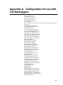
Alternatively you can change the parameters manually. Appendix A lists the
CSI template which gives the settings for each parameter.
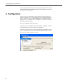
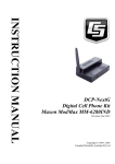
Follow all the steps in Section 2 of the AirLink manual up through Section 2.2
step 13. At this point if you have copied the CSI template file you can load it.
Select “Open Template” from the file menu:
2
Redwing Digital Cellular Modem
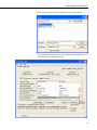
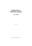
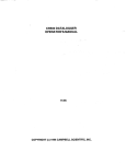
In the “Open” dialog box, select the template file that you downloaded.
After selecting the file, the values from the template file will appear in the New
Value column in the configuration listing.
3
Redwing Digital Cellular Modem
Check that the side preference is correct (step 11 in Airlink manual). To
complete the configuration, proceed to step 14 in the AirLink manual (Set IP
Address).
4. Power Considerations
If the installation’s power supply has a battery charger connected to reliable
AC power, the Redwing can be left on continuously, allowing the station to be
called at any time. If the Redwing is powered continuously, the power
requirements make it unfeasible to power the system from batteries alone for
other than short periods. Most remote installations use solar panels for
charging the batteries.
For continuous year-round power with a datalogger/sensor power requirement
as described below, the MSX20 or MSX20R solar panel is adequate for areas
in the United States other than parts of the Pacific Northwest, great lakes
region, and Alaska. The MSX10 or MSX10R should provide enough power in
the sunnier South and Southwest or if the cellular modem is powered less than
half of the time. (For more information on solar panel sizing check out: BP
Solar’s solar system design guide at:
http://www.bpsolar.com/ContentDetails.cfm?page=61 )
A power budget can be calculated to determine the length of time the system
will run on fully charged batteries without AC or solar charging. The number
of Amp-hours required per day can be calculated with the following equation:
Amp-Hours per day = (standby current)*(Time in standby) + (Transmitting
current)*(Time Transmitting) + (Average datalogger/sensor current) * 24 hours
If the Redwing is powered continuously and Transmits for 15 minutes per day
this works out to:
Standby (60 mA receiving) = 0.06 A * 23.75 hours = 1.43 Amp-hours
Transmitting (280 mA) = 0.28 A * 0.25 hours = 0.07 Amp-hours
Datalogger/Sensors (2.5 mA) = 0.0025 A * 24 hours = 0.06 Amp-Hours
Total = 1.56 Amp-hours
The datalogger and sensor power requirements above are for a typical weather
station application. (For more information on calculating power requuirements,
refer to Campbell Scientific’s power supply application note, available at:
http://www.campbellsci.com/apnotes.html#misc )
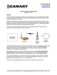
With the power budget calculated above, Campbell Scientific power supplies
will allow the cellular system to operate for approximately the number of days
listed below without charging (as might be the case with AC power failure or a
damaged solar panel. The calculation of the ammount of time assumes that the
battery is completely charged at the beginning of the period.
4
Redwing Digital Cellular Modem
NOTES:
Model
PS12LA
BP12
BP24
Charging Source/
Notes
Battery
1
7 Ahr
1,2
12 Ahr
1,2,3
24 Ahr
Approximate
Operating days
4
7
15
1.
10 watt solar panel recommended as charging source in
remote applications, model MSX10
2.
12VDC regulator, model CH12R
3.
Larger enclosure required, model ENC 16/18
To preserve battery life in solar powered systems, the battery Amp-hour
capacity used to calculate reserve capacity should be multiplied by 0.5 (i.e., the
net result is to cut the number of days listed above in half.) A ten day reserve
battery capacity is recommended. To get to a ten day reserve capacity, reduce
the amount of time that the modem is powered with the above batteries or get a
larger capacity battery. Note that in the power budget calculated above, the
majority of the power is consumed by keeping the modem powered even
though it is not being used. Powering it only half as long would essentially cut
the power requirements in half (program examples, section 6).
A user-supplied “RV” or “marine” deep cycle battery is an economical battery
with a larger capacity (60 – 100 Amp hours). Such a battery can be charged
with the MSX20R solar panel and housed outside the enclosure.
5. Installation
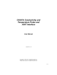
5.1 Datalogger Site Equipment
•
Redwing Modem and power cable.
•
Datalogger—CR510, CR10(X), CR23X, CR7, or CR5000.
•
SC932 or SC932A Interface—converts the modem’s RS-232 port to the
datalogger's CS I/O port. The 10871 9-to-25-pin adapter is required to
connect the Redwing to an SC932 Interface. The adapter is not necessary
for the SC932A. Alternatively when using a CR23X or CR5000, a 14393
Null Modem Cable can be used to connect the modem to the datalogger’s
RS-232 port instead of the CS I/O port.
•
14394 Redwing Mounting Kit w/ Adapter—includes mounting hardware
for securing the modem to an environmental enclosure and the SC12
cable.
•
Antenna—the following antennas can be purchased from Campbell
Scientific; sites near the edge of the CDPD coverage require the Yagi
antenna. Contact an Applications Engineer for help in determining the
best antenna for your application.
5
Redwing Digital Cellular Modem
14453
14454
2 dB ½ Wave Dipole Whip Cellular Antenna
8 dB Yagi Cellular Antenna with 10' Cable
The 10530 antenna sold with the COM100 analog cellular phone can also
be used with the Redwing when upgrading from analog cellular to CDPD.
An RF adapter connector is required to connect the TNC female connector
on the Redwing to the mini UHF male connector on the 10530 cable (e.g.,
Radio Shack Part No. 278-148).
•
Power Supply.
•
Environmental Enclosure—typically an ENC 12/14 or ENC 16/18.
5.2 Power Considerations
The communication connection between the Redwing serial port and the CS
I/O port on the datalogger (or RS-232 on CR23X or CR5000) is made with the
following interfaces:
Datalogger CS I/O connection to Redwing Serial Port via SC932:
CS I/O >> SC12 Cable >> SC932 >> 10871 >> SC12 >> Serial Port
Datalogger CS I/O connection to Redwing Serial Port via SC932A:
CS I/O >> SC12 Cable >> SC932A SC12 >> Serial Port
CR23X or CR5000 RS-232 to Redwing Serial Port Via Null Modem
Dataloggger RS-232 >> 14392 Null Modem Cable >> Serial Port
A power cable included with the modem connects to the datalogger's 12 V or
switched 12 V terminal. Connection to the switched 12 V terminal allows the
datalogger to switch power to the modem during scheduled transmission
intervals, thereby conserving power.
Table 5-1. Power Cable Wiring for Continuous Power
Wire Color
Red
Black
CR10(X)
12V
G
CR23X, CR5000, CR21X
12V
Table 5-2. Power Cable Wiring for Switching Power under
Program Control
Wire Color
Red
Black
6
CR10X
Switched 12V
G
User Supplied
Jumper from
Control Port X
to SW 12 V
Ctrl
CR23X, CR5000
Switched 12V
Redwing Digital Cellular Modem
6. Programming to Switch Transceiver Power
Switching power to the transceiver allows the datalogger to maintain a lower
power budget by limiting communication to predetermined times. The
transceiver must be switched on before it can answer a call.
This section provides examples of datalogger programming to switch power. If
the power supply is sufficient to power the cellular transceiver continuously
without switching, no special programming is necessary.
The simplest program switches power on at specific times and off a fixed time
later. This can be accomplished with two Instructions. Instruction 92 sets the
port controlling the relay high to turn the power on and a second Instruction 92
sets the port low. In these examples, control port 1 controls the relay.
The following program switches the transceiver on at midnight for 15 minutes:
;{CR10X}
;
*Table 1 Program
01: 10.0
Execution Interval (seconds)
01: If time is (P92)
1: 0
Minutes (Seconds --) into a
2: 1440
Interval (same units as above)
3: 41
Set Port 1 High
02: If time is (P92)
1: 15
Minutes (Seconds --) into a
2: 1440
Interval (same units as above)
3: 51
Set Port 1 Low
*Table 2 Program
02: 0.0
Execution Interval (seconds)
*Table 3 Subroutines
End Program
With the transceiver on for 15 minutes following midnight, LoggerNet would
be set to call automatically once a day at 2 minutes after midnight. In some
areas there are discounts for calls during off hours.
7
Redwing Digital Cellular Modem
To allow contacting the station throughout the day, the transceiver can be
turned on for the first 10 minutes of each hour:
;{CR10X}
;
*Table 1 Program
01: 10.0
Execution Interval (seconds)
01: If time is (P92)
1: 0
Minutes (Seconds --) into a
2: 60
Interval (same units as above)
3: 41
Set Port 1 High
02: If time is (P92)
1: 10
Minutes (Seconds --) into a
2: 60
Interval (same units as above)
3: 51
Set Port 1 Low
*Table 2 Program
02: 0.0
Execution Interval (seconds)
*Table 3 Subroutines
End Program
Or one might want to power the transceiver for one hour at 10 a.m. and at 10
p.m.
;{CR10X}
;
*Table 1 Program
01: 10.0
Execution Interval (seconds)
01: If time is (P92)
1: 600
Minutes (Seconds --) into a
2: 720
Interval (same units as above)
3: 41
Set Port 1 High
02: If time is (P92)
1: 660
Minutes (Seconds --) into a
2: 720
Interval (same units as above)
3: 51
Set Port 1 Low
*Table 2 Program
02: 0.0
Execution Interval (seconds)
*Table 3 Subroutines
End Program
8
Redwing Digital Cellular Modem
Another option is to power the transceiver for the first 15 minutes of each hour.
;{CR10X}
;
*Table 1 Program
01: 10
Execution Interval (seconds)
1: If time is (P92)
1: 0
Minutes (Seconds --) into a
2: 60
Interval (same units as above)
3: 41
Set Port 1 High
2: If time is (P92)
1: 15
Minutes (Seconds --) into a
2: 60
Interval (same units as above)
3: 51
Set Port 1 Low
*Table 2 Program
02: 0.0000
Execution Interval (seconds)
*Table 3 Subroutines
End Program
Whatever the time that the program powers the transceiver, the station must be
called while the transceiver is on; it cannot answer a call at other times.
9
Redwing Digital Cellular Modem
This is a blank page.
10
Appendix A. Configuration for use with
CSI Dataloggers
[\N] Side Preference=3
[S110] Device Port=3001
[S116] Service ID Preference=3
[S111] Service ID=0/0/0
[S112] Channel List Mode=2
[S113] Channel
List=715,706,708,790,793,792,796,794,791,798,795,0,0,0,0,0,0,0,0,0,0,0,0,0,0,
0,0,0,0,0,0,0
[3W] 3 Watt Booster Support=0
[*DSIDE] Disable Side Switch=0
[#X] Debug Output=0
[S0] TCP Auto Answer Mode=1
[S7] TCP Establishment Timeout=20
[S50] Data Forwarding Timeout=1
[S51] Data Forwarding Character=0
[S53] Destination IP Address=0.0.0.0
[S53] Destination TCP/UDP Port=23
[S53] Destination Connect Mode=T
[S210] AT Command Compatibility=1
[S211] Ignore DTR=1
[MD] Startup Mode Default=0
[MD] UDP Mode Default=0
[S60] Telnet Echo Mode=0
[S82] UDP Half Open Mode=0
[S83] UDP Half Open Timeout=0
[AIP] Allow Any UDP IP=0
[HOR] UDP Half Open Response=0
[S220] Break On TCP Connect=0
[S221] Delay Connect Response=0
[E] Command Echo=1
[V] Command Response Mode=1
[Q] Quiet Mode=0
[X] Call Progress Result Mode=0
[TCPT] TCP Inactive Timeout=5
[TCPS] Specify TCPT in Seconds=0
[TCPX] Allow TCP Suspension=0
[*DATZ] Disable Reset on ATZ=1
[DAE] Disable AT Esc Sequence=1
[RKEY] Radio Transceiver Keying=0
[\Q] Flow Control=0
[S23] Baud Rate=9600
[S23] Data Bits=8
[S23] Parity=N
[MVOFF] Modbus-Variant Offset=1
[MVLEN] Modbus-Variant Length=0
[MVTYP] Modbus-Variant Type=0
[MVOPT] Modbus-Variant Options=0
[MVMSK] Modbus-Variant ID Mask=0
[FM] Friends Mode=0
A-1
Appendix A. Configuration for use with CSI Dataloggers
This is a blank page.
A-2