1
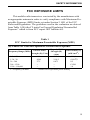
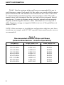
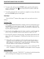
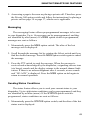
9800 Series
OPERATING
MANUAL
FM Mobile Radio
Conventional
SMARTNET™
SmartZone®
1
LAND MOBILE PRODUCT WARRANTY - The manufacturer’s
warranty statement for this product is available from your product
supplier or from the E.F. Johnson Company, 299 Johnson Avenue, Box
1249, Waseca, MN 56093-0514. Phone (507) 835-6222.
Copyright© 2000 by the E.F. Johnson Company
E.F. Johnson Company, which was founded in 1923, designs, manufactures, and markets radio communication products, systems, and services
worldwide. E.F. Johnson produces equipment for land mobile radio and
mobiletelephone services which include business, industrial, government,
public safety, and personal users.
Viking Head/EFJohnson logo and Call Guard® are trademarks of the E.F.
Johnson Company. SMARTNET™, SmartZone®, Call Alert™,
Enhanced Private Conversation™, and Private Conversation II™ are
trademarks of Motorola, Inc. All other company and/or product names
used in this manual are trademarks and/or registered trademarks of their
respective manufacturer.
SAFETY INFORMATION
SAFETY INFORMATION
The FCC has adopted a safety standard for human exposure to RF
energy. Proper operation of this radio under normal conditions results
in user exposure to RF energy below the Occupational Safety and
Health Act and Federal Communication Commission limits.
WARNING
DO NOT allow the antenna to touch or come in very close proximity
with the eyes, face, or any exposed body parts while the radio is transmitting.
To comply with FCC RF exposure limits, DO NOT operate the transmitter of a mobile radio when a person outside the vehicle is within
one (1) meter of the antenna.
To comply with FCC RF exposure limits, DO NOT operate the transmitter of a stationary radio (base station or marine radio) when a
person is within one (1) meter of the antenna.
DO NOT operate the radio in explosive or flammable atmospheres.
The transmitted radio energy could trigger blasting caps or cause an
explosion.
DO NOT operate the radio without the proper antenna installed.
DO NOT allow children to operate or play with this radio.
NOTE: The above warning list is not intended to include all hazards
that may be encountered when using this radio.
This device complies with Part 15 of the FCC rules. Operation is subject to the condition that this device does not cause harmful interference. In addition, changes or modifications to this equipment not
expressly approved by EFJohnson could void the user’s authority to
operate this equipment (FCC rules, 47CFR Part 15.19).
4
SAFETY INFORMATION
FCC EXPOSURE LIMITS
This mobile radio transceiver was tested by the manufacturer with
an appropriate antenna in order to verify compliance with Maximum Permissible Exposure (MPE) limits set under Section 2.1091 of the FCC
Rules and Regulations. The guidelines used in the evaluation are derived
from Table 1 (B) titled “Limits For General Population/Uncontrolled
Exposure” which is from FCC report OET bulletin #65.
Table 1
FCC Limits for Maximum Permissible Exposure (MPE)
(B) Limits For General Population/Uncontrolled Exposure
Frequency Range (MHz)
0.3 - 1.34
1.34 - 30
30 - 300
300 - 1500
1500 - 100,000
f = Frequency in MHz
Magnetic Field
Power Density (S)
Strength (H)
(mW/cm22)
(A/m)
614
1.63
(100)*
824/f
2.19/f
(180/f2)*
27.5
0.073
0.2
--f/1500
--1.0
*Plane-wave equivalent power density
Electric Field
Strength (E) (V/m)
5
SAFETY INFORMATION
Table 2 lists the antenna whips and bases recommended for use in
each frequency range. Each model of this radio was tested with the appropriate antenna listed. The antenna was mounted in the center of the roof
of a domestically manufactured four-door passenger sedan. The radio
manufacturer has determined that the user and service personnel should
remain one (1) meter in distance away from the antenna when transmitting. By maintaining this distance, these individuals are not exposed to
radio frequency energy or magnetic fields in excess of the guidelines set
forth in Table 1.
NOTE: Other antennas or installation configurations that have not been
tested may not comply with FCC RF exposure limits and therefore are not
recommended.
Table 2
Recommended Antenna Whips and Bases
(Antenna Manufacturer - Antenna Specialists)
6
Frequency
Whip Model No.
Base Model No.
136-144 MHz
144-152 MHz
152-162 MHz
162-174 MHz
400-430 MHz
430-470 MHz
470--512 MHz
806-869 MHz
890-960 MHz
ASPJ1415
ASPA1415
ASPB1415
ASPC1415
ASPE1615
ASPD1615
ASPF1615
ASPA1855
ASPG1865
KM220
KM220
KM220
KM220
KM220
KM220
KM220
KM220
KM220
TABLE OF CONTENTS
TABLE OF CONTENTS
SAFETY INFORMATION . . . . . . . . . . . . . . . . . . . . . . . . . . . . . . . . . . 4
FEATURES . . . . . . . . . . . . . . . . . . . . . . . . . . . . . . . . . . . . . . . . . . . . . . 9
General Features . . . . . . . . . . . . . . . . . . . . . . . . . . . . . . . . . . . . . . . . . 9
Conventional Features . . . . . . . . . . . . . . . . . . . . . . . . . . . . . . . . . . . . 9
SMARTNET™ II Features . . . . . . . . . . . . . . . . . . . . . . . . . . . . . . . . . 9
SmartZone® Features . . . . . . . . . . . . . . . . . . . . . . . . . . . . . . . . . . . . . 9
OPTION SWITCH FUNCTIONS . . . . . . . . . . . . . . . . . . . . . . . . . . . . 10
CONTROLS AND DISPLAY . . . . . . . . . . . . . . . . . . . . . . . . . . . . . . . 12
Front Panel Controls. . . . . . . . . . . . . . . . . . . . . . . . . . . . . . . . . . . . . 12
Rear Panel Jacks and Connectors . . . . . . . . . . . . . . . . . . . . . . . . . . . 13
GENERAL OPERATION . . . . . . . . . . . . . . . . . . . . . . . . . . . . . . . . . . 15
Introduction . . . . . . . . . . . . . . . . . . . . . . . . . . . . . . . . . . . . . . . . . . . 15
Turning Power On and Setting Volume . . . . . . . . . . . . . . . . . . . . . . 15
Backlight. . . . . . . . . . . . . . . . . . . . . . . . . . . . . . . . . . . . . . . . . . . . . . 16
Option Switches . . . . . . . . . . . . . . . . . . . . . . . . . . . . . . . . . . . . . . . . 16
Channel and Zone Selection . . . . . . . . . . . . . . . . . . . . . . . . . . . . . . . 16
Home Zone . . . . . . . . . . . . . . . . . . . . . . . . . . . . . . . . . . . . . . . . . . . . 17
Time-Out Timer . . . . . . . . . . . . . . . . . . . . . . . . . . . . . . . . . . . . . . . . 17
Tone Enable/Disable . . . . . . . . . . . . . . . . . . . . . . . . . . . . . . . . . . . . 18
Power Turn-Off Delay . . . . . . . . . . . . . . . . . . . . . . . . . . . . . . . . . . . 18
Scanning . . . . . . . . . . . . . . . . . . . . . . . . . . . . . . . . . . . . . . . . . . . . . . 19
Conventional and SMARTNET/SmartZone Operation . . . . . . . . . . 23
CONVENTIONAL FEATURES . . . . . . . . . . . . . . . . . . . . . . . . . . . . . 24
Introduction . . . . . . . . . . . . . . . . . . . . . . . . . . . . . . . . . . . . . . . . . . . 24
Display Mode Selection . . . . . . . . . . . . . . . . . . . . . . . . . . . . . . . . . . 25
Monitoring Before Transmitting . . . . . . . . . . . . . . . . . . . . . . . . . . . 25
Monitor Mode. . . . . . . . . . . . . . . . . . . . . . . . . . . . . . . . . . . . . . . . . . 26
Busy Channel Lockout . . . . . . . . . . . . . . . . . . . . . . . . . . . . . . . . . . . 26
Call Guard Squelch. . . . . . . . . . . . . . . . . . . . . . . . . . . . . . . . . . . . . . 27
Penalty Timer . . . . . . . . . . . . . . . . . . . . . . . . . . . . . . . . . . . . . . . . . . 27
Conversation Timer . . . . . . . . . . . . . . . . . . . . . . . . . . . . . . . . . . . . . 28
Repeater Talk-Around . . . . . . . . . . . . . . . . . . . . . . . . . . . . . . . . . . . 28
Power Output Select . . . . . . . . . . . . . . . . . . . . . . . . . . . . . . . . . . . . . 28
Conventional Mode Scanning . . . . . . . . . . . . . . . . . . . . . . . . . . . . . 29
7
TABLE OF CONTENTS
Priority Channel Sampling . . . . . . . . . . . . . . . . . . . . . . . . . . . . . . . . 30
Standard Conventional Calls . . . . . . . . . . . . . . . . . . . . . . . . . . . . . . 31
DTMF/ANI Signaling . . . . . . . . . . . . . . . . . . . . . . . . . . . . . . . . . . . 32
SMARTNET/SMARTZONE FEATURES . . . . . . . . . . . . . . . . . . . . 32
Introduction . . . . . . . . . . . . . . . . . . . . . . . . . . . . . . . . . . . . . . . . . . . 32
Viewing Unit ID . . . . . . . . . . . . . . . . . . . . . . . . . . . . . . . . . . . . . . . . 32
Standard Group Calls . . . . . . . . . . . . . . . . . . . . . . . . . . . . . . . . . . . . 33
Enhanced Private Conversation Calls . . . . . . . . . . . . . . . . . . . . . . . 34
Private Conversation II Calls . . . . . . . . . . . . . . . . . . . . . . . . . . . . . . 37
Telephone Calls . . . . . . . . . . . . . . . . . . . . . . . . . . . . . . . . . . . . . . . . 39
Call Alert . . . . . . . . . . . . . . . . . . . . . . . . . . . . . . . . . . . . . . . . . . . . . 41
Messaging. . . . . . . . . . . . . . . . . . . . . . . . . . . . . . . . . . . . . . . . . . . . . 42
Sending Status Conditions . . . . . . . . . . . . . . . . . . . . . . . . . . . . . . . . 43
Emergency Alarm/Call . . . . . . . . . . . . . . . . . . . . . . . . . . . . . . . . . . . 44
Failsoft Operation . . . . . . . . . . . . . . . . . . . . . . . . . . . . . . . . . . . . . . . 45
SMARTNET/SmartZone Scanning . . . . . . . . . . . . . . . . . . . . . . . . . 45
Dynamic Regrouping . . . . . . . . . . . . . . . . . . . . . . . . . . . . . . . . . . . . 46
SmartZone Features . . . . . . . . . . . . . . . . . . . . . . . . . . . . . . . . . . . . . 46
MISCELLANEOUS . . . . . . . . . . . . . . . . . . . . . . . . . . . . . . . . . . . . . . . 48
Supervisory Tones . . . . . . . . . . . . . . . . . . . . . . . . . . . . . . . . . . . . . . 48
Dealer Programming . . . . . . . . . . . . . . . . . . . . . . . . . . . . . . . . . . . . 50
Speaking Into Microphone . . . . . . . . . . . . . . . . . . . . . . . . . . . . . . . . 50
Operation At Extended Range . . . . . . . . . . . . . . . . . . . . . . . . . . . . . 50
Preventing Battery Discharge. . . . . . . . . . . . . . . . . . . . . . . . . . . . . . 50
Licensing . . . . . . . . . . . . . . . . . . . . . . . . . . . . . . . . . . . . . . . . . . . . . 51
Transceiver Service . . . . . . . . . . . . . . . . . . . . . . . . . . . . . . . . . . . . . 51
INDEX . . . . . . . . . . . . . . . . . . . . . . . . . . . . . . . . . . . . . . . . . . . . . . . . . . 53
8
FEATURES
FEATURES
General Features
•
•
•
•
•
16 Zones with Home Zone Select
16 Channels per Zone (256 Channels Total)
Radio-Wide Scan
Time-Out Timer
LCD 16-Character Alphanumeric Display with 8 Status Annunciators
Conventional Features
•
•
•
•
•
•
•
•
•
•
Channel Scan with User Programmable Scan Lists
Priority Channel Sampling
Busy Channel Lockout
Monitor Mode
Call Guard Squelch Control
Penalty Timer
Conversation Timer
Repeater Talk-around
DTMF/ANI Signaling
User Selectable Power Output
SMARTNET™ II Features
•
•
•
•
•
•
•
Group, Enhanced Private Conversation™, Private Conversation II™,
and Telephone Calls
Call Alert™ (Paging)
Emergency Calls
Messaging
Priority Monitor Scanning
Failsoft Operation
Dynamic Regrouping
SmartZone® Features
•
•
•
Site Trunking
Site Search
Site Lock/Unlock
9
OPTION SWITCH FUNCTIONS
OPTION SWITCH FUNCTIONS
S
EMER
C P
F1
F2
F3
SCAN
The five programmable option switches with the standard labels are
shown above. Each of these switches can control one function in the
Conventional mode and another in the SMARTNET/SmartZone mode.
The following tables indicate the functions available in each mode, the
key cap label which may be used, and the page in this manual on which
the function is described. Since keys can control two different functions
and additional labels are optional, the label may not always indicate the
function or a blank or “Fx” key cap may be used. Refer to page 16 for
more option switch information.
CONVENTIONAL MODE
Key Cap Label
BKLHT
DISP
TxPWR
MON
SELSQ
PRIED
RWS
SCAN
TONES
10
Function
Backlight On-Off
Displayed Information
High/Low Power
Home Zone
Monitor
Normal/Selective Squelch
Priority Edit
Radio Wide Scan
Repeater Talk-Around
Scanning On-Off
Scan List Edit
Tones On-Off
Zone Select
See Page
16
25
28
17
26
27
30
20
28
19
22
18
16
OPTION SWITCH FUNCTIONS
SMARTNET/SMARTZONE MODE
Key Cap Label
BKLHT
ALERT
RESP
EMER
MSG
PHONE
RWS
SCAN
STATUS
TONES
Function
Backlight On-Off
Call Alert
Call Response
Emergency
Home Zone
Message
Phone
Private Call
Radio Wide Scan
Scanning On-Off
Site Lock
Site Search
Status
Tones On-Off
Zone Select
See Page
16
42
36, 39
44
17
43
39
34, 37
20
19
47
47
43
18
16
11
CONTROLS AND DISPLAY
CONTROLS AND DISPLAY
Transmit/Busy
Indicator
S
Option Switches
C P
Speaker
F1
F2
EMER
F3
SCAN
Microphone
Jack
On-Off/Volume
Select Switch
Front Panel Controls
On-Off Volume - Pressing this knob turns power on and off, and rotating
it sets the speaker volume (see page 15).
Select Switch - Rotating this switch increases or decreases the selected
channel. It is also used for other functions such as selecting the zone and
scrolling through lists. Refer to “Channel and Zone Selection” on page 16
for more information.
Option Switches - The five front panel option switches can be
programmed by your dealer for various functions (see page 10).
Transmit/Busy Indicator - Indicates the following conditions:
Red - Transmitter is keyed
Green - The currently selected receive channel may be busy because a
carrier (signal) is being detected (see page 25).
Microphone Jack - Connection point for the microphone.
12
CONTROLS AND DISPLAY
Microphone Push-To-Talk (PTT) Switch (Not Shown) - Pushbutton on the microphone which is pressed to key the transmitter.
Speaker - The internal speaker is located behind the grille. An optional
speaker can be connected to the external speaker jack located on the back.
Refer to “Speaker Jack” description which follows.
Antenna
Jack
Power
Jack
Speaker
Jack
Rear Panel Jacks and Connectors
Antenna Jack - Miniature UHF jack for connecting the 50-ohm
antenna.
Power Jack - Connection point for the power cable which attaches to the
vehicle battery. A nominal 12-volt DC, negative ground power source is
required.
Speaker Jack - Connection point for an optional external 4.7-ohm,
5-watt speaker. The internal speaker is automatically disabled when a
speaker is plugged into this jack.
13
CONTROLS AND DISPLAY
Std Scan
Enabled
In Scan
List
Telephone
Call
Private
Call
Priority
Channel
C P
S
Upper 8-Character
Display
RadioWide Scan
Talk-Around
Mode
Monitor
Mode
Lower
8-Character
Display
Display Description
Upper 8-Character Display - This alphanumeric display indicates the
channel alias or information about the selected mode. With conventional
operation, it may also indicate the channel number or frequency (see
“Display Mode Selection” on page 25).
Lower 8-Character Display - This alphanumeric display indicates additional information pertaining to the current mode when necessary.
- Indicates that standard scanning is enabled (see page 19). Standard
and radio wide scanning cannot be enabled at the same time.
- The box around the “S” indicates that the current channel is in the
standard scan list (page 21).
- With SMARTNET/SmartZone channels only, indicates that the
telephone call mode is selected (page 39).
- Indicates that radio-wide scan is enabled (see page 20).
14
GENERAL OPERATION
- Indicates that repeater talk-around is enabled on the selected conventional channel (see page 28).
- Indicates that a SMARTNET/SmartZone private call is occurring
(pages 34 and 37).
- Indicates that the conventional monitor mode is enabled (page 26).
- Indicates that the selected conventional channel is a priority channel
(page 30).
GENERAL OPERATION
Introduction
The following section describes features available with both trunked
and conventional operation. Features unique to conventional channels are
described starting on page 24, and features unique to SMARTNET/
SmartZone channels are described starting on page 32.
Turning Power On and Setting Volume
Power is turned on and off by pressing the On-Off/Volume switch on
the front panel. When power is initially turned on, an alert tone sounds
and the radio software version is momentarily displayed. The zone alias
is then displayed followed by the unit ID if a SMARTNET/SmartZone
channel is selected (see page 33). The selected channel is then indicated.
When power is turned off, the display may remain on for a short time. It
is recommended that power not be turned back on again until the display
is blank.
The volume level is adjusted by rotating the On-Off/Volume switch.
The relative volume level can be determined by noting the position of the
index on the knob. You may also be able to enable a reference tone for
setting the volume as follows:
•
If key press tones are enabled (see page 18), a short tone sounds when
front panel option keys are pressed.
15
GENERAL OPERATION
•
If a conventional channel is selected and the MON (Monitor) option
switch is programmed (see page 26), pressing that switch unsquelches/
squelches the receiver and either voice or background noise is heard. If
a SMARTNET/SmartZone channel is selected, the receiver cannot be
manually unsquelched.
Backlight
The backlight for the display and keypad can be manually turned on
and off if the BKLHT option switch is programmed. Pressing this switch
cycles between the Bright, Dim, and Off modes. If this switch is not
programmed, the backlight is fixed in one of these modes.
Option Switches
All five push-button switches on the front panel are programmable
for various functions. If your radio is programmed with both conventional and SMARTNET/SmartZone channels (see page 23), these option
switches can be dealer programmed to control a different set of functions
for each channel type. For example, a switch could select Monitoring
when a conventional channel is selected and Private calls when a
SMARTNET/SmartZone channel is selected.
The available functions in each mode are indicated in the tables on
pages 10 and 11. If the functions controlled by your switches are not indicated in these tables or by the key cap label, consult your dealer to determine how your switches have been programmed. If no option switch has
been programmed to control a particular function, that function may not
be available or may be in a fixed mode.
Channel and Zone Selection
Channel Select
To change the selected channel, rotate the Select switch. The
selected channel alias (name) is indicated on the top line of the display.
With conventional channels, the channel number or frequency may also
be displayed (see “Display Mode Selection” on page 25).
16
GENERAL OPERATION
Zone Select
A zone is a group of up to any 16 conventional and SMARTNET/
SmartZone channels defined by dealer programming. Up to 16 zones can
be programmed for a total of 16 x 16 or 256 channels. One use of zones
may be to select groups of channels programmed for operation in
different geographical areas or radio systems. If selectable zones have
been programmed in your radio, consult your dealer for more information
on how they are used. Zones are selected as follows:
1. Press the Zone option switch and the alias (name) of the current zone is
indicated on the upper line of the display.
2. Rotate the Select switch to display the desired zone. Then to select that
zone and exit this mode, press the Select switch or wait 4 seconds.
Home Zone
The radio can be programmed with a home zone. Then when power
is turned on, the radio can be programmed so that either the home zone or
last selected zone is automatically selected.
If the Home Zone option switch is programmed, it can be used to
quickly select or change the home zone. To select the home zone, simply
press this switch. To change the home zone to the currently selected zone,
press and hold this switch until a tone sounds (approximately 1 second).
Time-Out Timer
The time-out timer disables the transmitter if it is keyed for longer
than the programmed time. It can be programmed on each channel for
times from 15 seconds up to 3 minutes, 45 seconds or disabled (not used).
If the transmitter is keyed continuously for longer than the programmed
time, the transmitter is disabled and an invalid condition tone sounds.
Five seconds before time-out occurs, an alert tone sounds to indicate that
time-out is approaching. The timer and tone are reset by releasing the
PTT switch.
17
GENERAL OPERATION
One use of this feature is to prevent a channel from being kept busy
for an extended period by an accidentally keyed transmitter. It can also
prevent possible transmitter damage caused by transmitting for an excessively long period. Conventional channels can also be programmed with
the Penalty and Conversation timers that are described starting on
page 27.
Tone Enable/Disable
The supervisory tones (see page 48) can be enabled and disabled by
the TONES option switch if it is programmed. When tones are enabled
by this switch, “TONE ON” is momentarily displayed on the lower line
and a tone sounds. Conversely, when tones are disabled, “TONE OFF” is
displayed and no tone sounds. If the TONES option switch is not
programmed, tones are fixed in the on or off mode by dealer
programming.
Power Turn-Off Delay
Your transceiver can be installed so that the vehicle ignition switch
as well as the front panel power switch control transceiver power. If this
is the case, both the ignition switch and the front panel power switch
must be on for transceiver power to turn on.
When the ignition switch controls power, a turn-off delay of up to
254 minutes can be programmed. The delay can be overridden at any
time by turning power off using the front panel power switch or turning
the ignition switch back on. A turn-off delay allows calls to be received
for a time after the ignition switch is turned off. At the same time, advantages of ignition switch control are utilized such as preventing the battery
discharge that may occur if the transceiver is left on for an extended
period (see page 51).
18
GENERAL OPERATION
Scanning
Introduction
Scanning monitors channels in the scan list for messages your transceiver is programmed to receive. When a message is detected, scanning
stops and the message is received. Shortly after the message is complete,
scanning resumes (unless it has been disabled). The microphone does not
need to be on-hook for scanning to occur. However, if it is off-hook and
conventional channels are scanned, coded squelch is disabled (see
page 27) so all calls occurring on those channels are received.
There are two basic scan modes: Standard and Radio Wide. The
Standard mode is unique to the type of channel selected (conventional or
SMARTNET/SmartZone), and the Radio Wide mode is the same regardless of the channel type selected. Only one of these scan modes can be
enabled at a time. Therefore, if standard scanning is enabled while radio
wide scanning is occurring, radio wide scanning is automatically disabled
and vice versa. More information on these modes follows.
Standard Scanning
Standard scanning monitors only channels that are the same type as
that currently selected. Therefore, if a conventional channel is selected,
only conventional channels are scanned, and if a SMARTNET channel is
selected, only SMARTNET channels are scanned. Standard scanning is
turned on and off by the SCAN option switch as follows. If this switch is
not programmed, standard scanning is not available.
•
To turn standard scanning on, press the SCAN option switch. Scanning
is enabled when the “S” icon is indicated in the upper left corner of the
display and SCAN x (conventional) or SCAN ON (SMARTNET/
SmartZone) is briefly displayed on the lower line of the display. The
“x” is the number of the conventional scan list (1, 2, or 3) that is
selected. Refer to page 29 for more information.
•
To turn scanning off, press the SCAN option switch again. The “S”
icon is then no longer indicated and “SCAN OFF” is briefly displayed.
19
GENERAL OPERATION
•
If the zone or channel is changed while scanning is selected, scanning
continues on the same or a different scan list (see scan list information
which follows).
Radio Wide Scanning
Radio wide scanning monitors the channels in the preprogrammed
radio wide scan list (see page 20). This list may contain up to 16 channels
of any type (conventional or SMARTNET/SmartZone) assigned to any
zone. Radio wide scanning is turned on and off by the RWS option
switch as follows. If this switch is not programmed, radio wide scanning
is not available.
•
To turn radio wide scanning on, press the RWS option switch. The
icon is then displayed continuously and “RWS ON” is displayed briefly
on the lower line of the display.
•
To turn radio wide scanning off, press the RWS option switch again.
The
icon is then no longer indicated and “RWS OFF” is displayed
briefly.
•
If the zone or channel is changed while radio wide scanning, scanning
continues normally.
Scan Resume Delay
When a message is received or transmitted while scanning, there is a
dealer programmable delay before scanning resumes. The delay after
receiving a call prevents another message from being received before you
can make a response, and the delay after transmitting a call ensures that
you hear a response to your call instead of another message occurring on
some other channel.
Standard Mode Scan List
NOTE: The selected channel is always scanned.
With conventional operation, up to three scan lists can be
programmed. The list that is scanned is selected by the SCAN option
20
GENERAL OPERATION
switch as described on page 29. Selecting another conventional channel
does not change the current scan list. The scan lists are user programmable if the Scan Edit option switch is programmed (see page 22).
With SMARTNET/SmartZone operation, each channel can be
programmed so that one of up to three different scan lists is automatically
selected or scanning is disabled. The scan lists are user programmable if
the Scan Edit option switch is programmed (see page 22).
Radio Wide Mode Scan List
With radio wide scanning, there is only one preprogrammed scan list
available regardless of the type of channel selected, and it is not user
programmable.
Determining Which Channels are in Scan List
Channels in the conventional standard scan lists are indicated as
follows. Channels in the SMARTNET/SmartZone standard scan lists are
indicated only when editing a scan list as described on page 22. Channels
in the radio wide scan list are not indicated.
1. Enable standard scanning and also select the scan list if applicable (see
page 29).
2. Select the desired zone and then scroll through the channels by rotating
the Select switch. When the displayed channel is in the scan list
(scanned normally), the box
icon (around “S”) is indicated in the
upper left corner of the display
Nuisance Channel Delete
With standard scanning, conventional and SMARTNET/SmartZone
channels can be temporarily deleted from the scan list, for example, if
messages on a channel become annoying. This feature is not available
with radio wide scanning. Proceed as follows:
21
GENERAL OPERATION
NOTE: The selected channel and conventional priority channels cannot
be deleted from the scan list.
1. While receiving a message on the channel to be deleted, press and hold
the SCAN option switch until the alert tone sounds (about 1 second).
2. The channel is then deleted and scanning of the remaining channels in
the scan list resumes.
3. Deleted channels are added back into the scan list if either of the
following occur:
•
•
•
Scanning is turned off and then on again using the SCAN switch.
The selected channel is changed.
Transceiver power is turned off and then on again.
Programming a Scan List
If the Scan Edit option switch is programmed, conventional and
SMARTNET/SmartZone standard scan lists can be user programmed as
follows:
1. Make sure that both standard and radio wide scanning are off (neither
the standard scan “S” icon or radio-wide scan
icon is displayed).
Then press the Scan Edit option switch to select the scan list edit mode.
2. With conventional channels, if applicable, select the list to be edited
(1-3) by rotating and then pressing the Select switch. The selected list
is indicated as “SCAN x”, where “x” is the list number from 1-3. If user
programming is disabled on a list, “NO LIST” is momentarily
displayed and it cannot be edited.
With SMARTNET/SmartZone channels, the scan list for the selected
channel is fixed and cannot be changed. Scanning may also be disabled
on the channel in which case “NO LIST” is momentarily displayed and
scan list editing is not available.
22
GENERAL OPERATION
3. Select the channel you want to add or delete by rotating the Select
switch. After the last conventional channel in the current zone is
displayed, the first valid channel in the next zone is displayed and vice
versa. SMARTNET/SmartZone lists are limited to 16 channels. If an
attempt is made to add more than 16, “LIST FULL” is displayed and a
channel must be deleted before another can be added.
4. If the selected channel is in the scan list (scanned), the box
icon
(around “S”) is indicated in the upper left corner of the display. To
change the status of the displayed channel, press the Select switch.
NOTE: The priority channel cannot be deleted (see “Priority Channel
Sampling” description which follows).
5. To exit this mode and save the changes, press the Scan Edit option
switch again.
Conventional and SMARTNET/SmartZone Operation
Introduction
Each selectable channel is dealer programmable for either conventional or SMARTNET™/SmartZone® (trunked) operation. For example,
Zone 1/Channel 1 could be a conventional channel, Zone 1/Channel 2 a
SMARTNET/SmartZone channel, and so on. Consult your dealer to
determine the type or types of operation programmed in your radio. More
information on these modes follows.
Conventional Operation
This is a non-trunked operating mode which accesses independent
radio channels (there is no automatic access to several channels as with
trunked operation). Monitoring before transmitting may not occur automatically in this mode, so you may have to manually monitor the channel
before transmitting to make sure that it is not being used by anyone else
(see page 25). Selecting a conventional channel selects a transmit and
receive frequency and other parameters such as Call Guard squelch
coding.
23
CONVENTIONAL FEATURES
SMARTNET/SmartZone Operation
This is a trunked operating mode that uses ID codes to select which
mobiles are being called and which calls are received. Monitoring is
performed automatically and special messages and tones indicate busy
and out-of-range conditions. Enhanced features include roaming (SmartZone only), telephone, private, and emergency calls, Call Alert, and
messaging. Operating features unique to SMARTNET/SmartZone
channels are described starting on page 32.
This radio supports only the SMARTNET II trunking protocol. It
does not support the SMARTNET I (also referred to as Type I) protocol.
When a SMARTNET or SmartZone channel is selected or the radio is
powered up on one of those channels, it searches for a control channel
and attempts to register on the radio system. Once a control channel is
found, the alias (name) of the selected channel is displayed. If a control
channel could not be found (because of an out of range condition or the
system ID is not correct, for example), “NO SYS” is displayed and the
radio continues to search for a control channel.
The control channel transmits and receives system information to
and from all radios registered on the system. Therefore, once a control
channel is found, it is continuously monitored for incoming call information and is used to make call requests. The radio automatically changes to
a traffic channel to place and receive calls and then returns to the control
channel when the call is complete.
CONVENTIONAL FEATURES
Introduction
The following information describes features unique to the conventional operating mode (see brief description on preceding page). Refer to
the preceding “General Operation” section for information on features
common to all operating modes, and to the SMARTNET/SmartZone
section starting on page 32 for information on features unique to that
mode.
24
CONVENTIONAL FEATURES
Display Mode Selection
If the DISP (Displayed Information) option switch is programmed,
the display mode used to indicate conventional channels can be user
selected. Pressing this switch cycles between the following modes. The
selected mode does not change when power is turned off. If the DISP
option switch is not programmed, the Alias mode is always selected.
Alias - The preprogrammed alphanumeric tag for the channel is
displayed.
Number - The channel number from 1-16 is displayed.
Frequency - The receive frequency of the selected channel is displayed
in megahertz.
Monitoring Before Transmitting
With conventional operation, you may need to manually monitor the
channel before transmitting to make sure that it is not being used by
someone else. If you were to transmit while someone else was using the
channel, you would probably disrupt their conversation. Channels are
monitored automatically or manually as follows:
Automatic Channel Monitoring
If the selected channel is programmed for the Busy Channel Lockout
feature (consult your dealer), monitoring is performed automatically.
Refer to the description of this feature on page 26 for more information.
Manual Channel Monitoring
The automatic monitoring just described may not be programmed or
it may occasionally disable the transmitter even if the channel is not in
use. In this case, the channel must be monitored manually as follows:
Busy Indicator - With scanning disabled, note if the Transmit/Busy
indicator on the front panel is green. If it is not, the channel is not being
used and you can transmit your call. If it is on, the channel may be busy
and you should not place your call (see next paragraph).
25
CONVENTIONAL FEATURES
Monitor Mode - There may be times when the busy indication is
displayed even though no one is using the channel. Monitoring should
then be performed by disabling Call Guard squelch by taking the microphone off-hook or pressing the SELSQ option switch as described on
page 27 or by selecting the monitor mode as described next.
Monitor Mode
The monitor mode temporarily disables squelch control features
(such as Call Guard® squelch) so that all messages are heard on the
selected channel. It also overrides the Busy Channel Lockout feature (see
next section) and temporarily disables scanning.
To monitor the selected channel, select the monitor mode by briefly
pressing the MON option switch (if available). The
icon is displayed
and the receiver unsquelches when the monitor mode is enabled. To
disable the monitor mode and return to normal operation, press the MON
switch a second time.
When scanning is enabled, pressing and holding the MON option
switch until a tone sounds (approximately 1 second) monitors the scanned
channel instead of the selected channel.
Busy Channel Lockout
The Busy Channel Lockout feature (also called Transmit Disable On
Busy) automatically disables the transmitter if the channel is busy when
the PTT switch is pressed. When a busy condition is detected by this
feature, the transmitter is disabled, “BUSY” is indicated on the lower line
of the display, and a tone similar to a standard telephone busy tone
sounds until the PTT switch is released. This feature is programmed to
operate in one of the following modes on each channel:
Off - The transmitter keys even if the channel is busy.
Noise - The transmitter is disabled if any signal is detected on the
channel.
Tone - The transmitter is disabled if the detected squelch coding is not
correct.
26
CONVENTIONAL FEATURES
If busy override is permitted by programming, it is possible to
transmit even when the transmitter is disabled by this feature. Simply
release the PTT switch and then quickly press it again.
Call Guard Squelch
General
Call Guard® squelch (also called CTCSS/DCS signaling) may be
programmed on conventional channels. This feature eliminates
distracting messages intended for others using the channel by using a
subaudible tone or digital code to control the squelch. This tone or code is
unique to a user or talk group on that channel. It is transmitted by the
mobile placing a call, and if Call Guard squelch is programmed in the
mobile receiving the call, it must detect the correct tone or code to
receive the call.
Call Guard Squelch Enable/Disable
To disable Call Guard (Selective) squelch so that all messages on the
selected or scanned conventional channels are heard, take the microphone
off-hook or press the SELSQ option switch if programmed. Then to reenable Call Guard squelch, place the microphone back on-hook or press
the SELSQ switch again. Microphone off-hook detection may also be
disabled by programming so that it does not disable Call Guard squelch.
When Call Guard squelch is disabled by the option switch, “SQ
NORM” is flashed on the lower line of the display, and when it is
enabled, “SQ SLCT” is flashed. The mode selected by this switch does
not change when other channels are selected or power is cycled. Call
Guard squelch can also be disabled by the monitor mode described on
page 26.
Penalty Timer
A penalty timer may be programmed on conventional channels to
prevent transmissions for a time after the time-out timer described on
page 17 disables the transmitter. The penalty timer starts when the PTT
27
CONVENTIONAL FEATURES
switch is released after the transmitter has been disabled. If the PTT
switch is pressed during the penalty time, the time-out indication occurs
again. A beep sounds when the penalty timer expires and the transmitter
can then be keyed.
Conversation Timer
A conversation timer can be programmed on conventional channels
to limit the total length of a conversation rather than just the length of
each transmission as with the time-out timer. This timer is reset when the
time between transmissions exceeds the penalty time just described. A
warning tone sounds 5 seconds before the conversation timer expires.
When it expires, the transmitter is disabled and a warning tone sounds.
The transmitter remains disabled for the length of the penalty time, and a
beep sounds when it can be keyed again.
Repeater Talk-Around
Normally, all your transmissions go through a repeater which
usually increases range. However, if you are out of range of the repeater,
you cannot talk to anyone else on that channel even though the mobile
you are calling may be only a short distance away. To allow communication when this situation occurs, repeater talk-around can be used to allow
direct communication with a mobile without going through a repeater.
Repeater talk-around can be selected if the Repeater Talk-Around
option switch is programmed. When talk-around is enabled by this
switch, the
icon is displayed and “RTA ON” is flashed on the lower
line of the display. Then when it is disabled by pressing the switch again,
that icon is no longer displayed and “RTA OFF” is flashed. Changing
channels or turning power off does not change the selected talk-around
mode.
Power Output Select
If the TxPWR option switch is programmed and power selection is
permitted on the current channel, either high or low transmitter power can
28
CONVENTIONAL FEATURES
be selected. Generally, the high power setting allows you to transmit
longer distances and the low power setting shortens the transmit distance.
Pressing the TxPWR switch toggles the power setting. The new
level is flashed on the lower line of the display when this switch is
pressed as “HI POWER” or “LO POWER”. If power selection is not
permitted on the current channel, the fixed power level is flashed and no
power change occurs. Turning power off or changing channels does not
change the power setting selected for a channel.
Conventional Mode Scanning
General
The following information describes scanning features unique to
conventional operation. Scan operation common to all modes is described
starting on page 19, and scan operation unique to SMARTNET/SmartZone operation is described starting on page 45.
Selecting a Scan List
With conventional standard scanning, one of up to three scan lists
can be selected. Scanning is turned on and off and the scan list selected
by repeatedly pressing the SCAN switch as follows:
1. Press the SCAN option switch once to enable scanning and Scan
List 1. The “S” icon is then indicated in the upper left corner of the
display and “SCAN 1” is momentarily displayed on the bottom line.
2. Press the SCAN option switch again to select Scan List 2 (if available),
and “SCAN 2” is momentarily displayed. Press it again to select Scan
List 3 (if available).
3. Pressing the SCAN option switch again disables scanning (the “S”
icon is no longer displayed). If the SCAN option switch is pressed
again, the cycle repeats.
29
CONVENTIONAL FEATURES
Transmitting in Scan Mode
When the transmitter is keyed with scanning enabled, the radio can
be programmed so that the transmission always occurs on one of the
following channels:
•
•
•
Priority channel (see following description)
Selected channel
Channel of a call if the response is made before scanning resumes
Priority Channel Sampling
General
The priority channel sampling feature ensures that when standard
scanning, messages on the priority channel are not missed while listening
to a message on some other channel. Your transceiver can be
programmed so that the priority channel is a fixed channel associated
with the current scan list, the currently selected channel, or not used.
When the selected channel is a priority channel, “P” is indicated in the
upper right part of the display.
Priority channel sampling occurs only with Standard conventional
scanning. It does not occur with Radio Wide scanning, when listening to
any type of SMARTNET/SmartZone call, or when transmitting. A series
of “ticks” may be heard when the priority channel is sampled while
listening to a message on some other channel.
Changing The Priority Channel
If a specific priority channel is associated with the current scan list,
it can be changed if the PRIED option switch is programmed. Proceed as
follows:
1. Make sure all scanning is off (neither the standard scan “S” icon or
radio-wide scan
icon is displayed).
30
CONVENTIONAL FEATURES
2. Select the channel that you want to be the priority channel using the
Select switch in the normal manner. If the channel is in a different zone,
also select the appropriate zone.
3. Press the PRIED option switch and the “P” icon is displayed to indicate that the selected channel is now the priority channel.
Standard Conventional Calls
Standard conventional calls are calls to or from other mobile units
on the selected channel. The proper coded Call Guard signaling (see
page 27) may need to be transmitted for them to receive your call and
also for you to receive their calls. Proceed as follows to place and receive
these calls:
Placing a Standard Conventional Call
1. Turn power on and set the volume as described on page 15. Select the
channel programmed for the mobile you want to call (see “Channel and
Zone Selection” on page 16).
2. Monitor the channel automatically or manually as described on
page 25.
3. Press the PTT switch and the call proceeds as follows:
•
If the Busy Channel Lockout feature is programmed on the channel,
the transmitter is automatically disabled if the channel is busy (see
description on page 26).
•
Otherwise, busy and out-of-range conditions are not indicated and
speaking can begin after monitoring the channel.
4. Press (and hold) the PTT switch to talk and release it to listen.
Receiving a Standard Conventional Call
1. Select or scan the channel programmed for the call you want to receive
(refer to pages 19 and 29 for more scanning information).
31
SMARTNET/SMARTZONE FEATURES
2. When the call is received, press the PTT switch to talk and release it to
listen. If scanning, you may have to respond before scanning resumes
to ensure that the response occurs on the channel of the call.
DTMF/ANI Signaling
DTMF (Dual Tone Multi-Frequency) tones can be generated
manually or automatically for ANI (Automatic Number Identification)
and other purposes. The following options may be enabled by dealer
programming for each conventional channel:
DTMF Keypad - Pressing 0-9, *, or # on the keypad of an optional
DTMF microphone transmits the corresponding tone (the PTT switch
must also be pressed if the transmitter does not automatically turn on
when a key is pressed).
Pre-Tx ANI - A preprogrammed ANI sequence is automatically sent
when you press the PTT switch.
Post-TX ANI - A preprogrammed ANI sequence is automatically sent
each time you release the PTT switch.
Disabled - ANI signaling is disabled.
SMARTNET/SMARTZONE FEATURES
Introduction
The following information describes the features unique to the
SMARTNET/SmartZone operating mode (see page 23 for a description).
Features common to all operating modes are described starting on
page 15, and features unique to the conventional mode are described
starting on page 24.
32
SMARTNET/SMARTZONE FEATURES
Viewing Unit ID
Each radio in a SMARTNET system is identified with a system ID
and Unit ID. To display the Unit ID, make sure that a SMARTNET/
SmartZone channel is selected and then turn power off and then on again.
The software version number, current zone, and six-digit Unit ID are then
displayed in sequence. The Unit ID is displayed as IDxxxxxx.
Standard Group Calls
Standard calls are between you and another mobile, group of
mobiles, or a control station (a radio at a fixed location). Most calls you
make will probably be this type.
Placing a Standard Group Call
1. Turn power on and set the volume as described on page 15. Select the
channel programmed for the talk group you want to call (see page 16).
A regular or announcement talk group can be selected.
2. Press the PTT switch and when the alert tone sounds, begin talking.
Other indications that may occur are as follows:
•
If the busy tone sounds and “BUSY” is displayed, the system is busy.
Release the PTT switch and wait for the call back tone to sound. Then
press the PTT switch within 3 seconds and begin talking.
•
If a continuous tone sounds while pressing the PTT switch, you may
be out-of-range. Drive closer or away from shielding objects and try
again.
•
If your unit ID is invalid, the call is being made to an invalid group
ID, or group calls are not allowed, “INVALID ID” is displayed and an
alert tone sounds.
33
SMARTNET/SMARTZONE FEATURES
Receiving a Standard Call
Group calls are automatically received if a SMARTNET/SmartZone
channel is selected. The display continues to indicate the selected channel
tag (alias) when a call is received.
Enhanced Private Conversation Calls
General
Private calls allow you to place a call to a specific mobile unit.
Either the Enhanced Private Conversation™ or Private Conversation II™
modes may be programmed depending on the capabilities of the radio
system. Operation in the Enhanced Private Conversation mode is
described in the following information, and operation in the Private
Conversation II mode is described starting on page 37.
The Private Call option switch is required to place these calls, and
either that switch or the RESP (Call Response) option switch is required
to receive them.
Placing an Enhanced Private Conversation Call
This call is placed by selecting the unit ID from a preprogrammed
list or directly entering it using the keypad of an optional DTMF microphone. Proceed as follows.
Selecting Number From a List
1. With a SMARTNET/SmartZone channel selected, momentarily press
the Private Call option switch. The private call mode is then indicated
by “C” in the upper part of the display, and the alias (name) of the last
ID called is displayed on the upper line if it matches an ID in your call
list. Otherwise, the last ID called is displayed.
2. Scroll through the private call list by rotating the Select switch until the
desired ID is displayed. To cancel the call, press the Private Call switch.
34
SMARTNET/SMARTZONE FEATURES
3. Press the PTT switch to initiate the call. The display then indicates the
alias of the destination radio. Proceed to the bulleted list following the
next method for conditions that may occur next.
Direct Entry (With Microphone Keypad Only)
1. With a SMARTNET/SmartZone channel selected, press and hold the
Private Call option switch until a tone sounds (approximately 1
second). The private call mode is indicated by “C” in the upper part of
the display, and the last ID called is displayed on the upper line.
2. Using the 0-9, #, and
keys, enter the 6-digit ID of the mobile unit
you are calling. To erase the last digit entered, rotate the Select switch
counterclockwise, and to cancel the call, press the Private Call switch.
*
3. Press the PTT switch to initiate the call. If the entered ID is invalid,
“INVALID” is momentarily displayed and the call is not initiated. If the
entered ID is valid, the alias of the ID is displayed on the lower line if
it matches an ID in your call list. Otherwise, only the ID you entered
continues to be displayed. Conditions that may then occur are as
follows.
•
If the radio you are calling is on the air, telephone type “ringing” is
heard for 20 seconds or until the called party answers.
•
If the called party answers and the call is successful, the person’s
voice is heard and the call is carried on the same as a group call. To
end the call at any time, press the Private Call switch.
•
If the called party does not answer within 20 seconds, “NO ANSWR”
is displayed and a continuous tone sounds. End the call by pressing
the Private Call switch.
•
If the called radio is not in service, no ringing is heard, “NO ACK” is
displayed, and a continuous tone sounds. End the call by pressing the
Private Call switch.
35
SMARTNET/SMARTZONE FEATURES
•
If neither your radio nor the radio being called is authorized to make
unit-to-unit calls, “NO ACK” is displayed and a continuous tone
sounds. End the call by pressing the Private Call switch.
•
If the called party answers but the radio system is busy, four low tones
sound and “BUSY” is displayed. When the system is no longer busy,
the called party automatically responds.
•
If an out-of-range condition exists or the radio system is not in
service, “NO SYS” is displayed and a continuous tone sounds. End
the call by pressing the Private Call switch.
Receiving an Enhanced Private Conversation Call
This call is automatically received if a SMARTNET/SmartZone
channel is selected. Proceed as follows:
1. When this call is received, a recurring unit call tone (three beeps)
sounds for up to 20 seconds and “CALL RCV” is displayed on the
lower line.
2. To answer the call, press the Private Call option switch and then the
PTT switch and begin talking. The private call mode is indicated by
“C” in the upper part of the display, and the alias of the incoming call
is displayed if the ID is in your call list. Otherwise, the unit ID is
displayed. NOTE: If the Private Call option switch is not pressed before
the PTT switch, a group call is transmitted on the selected group.
•
To end the call when the conversation is complete or at any other time,
press the Private Call switch.
•
If private calls are not permitted (Private Call switch not
programmed), press the RESP (Call Response) option switch, if
available, to answer the call.
•
If the call is not answered within 20 seconds, it is automatically
terminated.
36
SMARTNET/SMARTZONE FEATURES
•
If the radio system is busy, four low tones sound and “BUSY” is
displayed. When the system is no longer busy, the call back tone (four
beeps) is heard and your radio automatically starts transmitting. Press
the PTT switch to continue the call.
•
To ignore an incoming call, wait 20 seconds until the recurring unit
call tone stops sounding.
Private Conversation II Calls
General
Private calls allow you to place a call to a specific mobile unit.
Either the Enhanced Private Conversation™ or Private Conversation II™
modes may be programmed depending on the capabilities of the radio
system. Operation in the Enhanced Private Conversation mode is
described starting on page 34, and operation in the Private Conversation
II mode is described in the following information.
The Private Call option switch is required to place these calls, and
either the Private Call or RESP (Call Response) option switch is
required to receive them.
Placing a Private Conversation II Call
This call is placed by selecting the unit ID from a preprogrammed
list or directly entering it using the keypad of an optional DTMF microphone. Proceed as follows.
Selecting Number From a List
1. With a SMARTNET/SmartZone channel selected, momentarily press
the Private Call option switch. The private call mode is indicated by
“C” in the upper part of the display, and the alias (name) of the last ID
called is displayed if it matches an ID in your call list. Otherwise, the
last ID called is displayed.
37
SMARTNET/SMARTZONE FEATURES
2. Scroll through the private call list by rotating the Select switch until the
desired ID is displayed. Press the Private Call switch again to cancel the
call.
3. Press the PTT switch to initiate the call. The display then indicates the
alias of the destination radio. Wait approximately 1 second and then
begin talking. Proceed to the bulleted list following the next method for
conditions that may occur next.
Direct Entry (With Microphone Keypad Only)
1. With a SMARTNET/SmartZone channel selected, press and hold the
Private Call option switch until a tone sounds (approximately 1
second). The private call mode is indicated by “C” in the upper part of
the display, and the last ID called is displayed on the upper line.
2. Using the 0-9, #, and
keys, enter the 6-digit ID of the mobile unit
you are calling. To erase the last digit entered, rotate the Select switch
counterclockwise, and to cancel the call, press the Private Call switch.
*
3. Press the PTT switch to initiate the call. If the entered ID is invalid,
“INVALID” is momentarily displayed and the call is not initiated. If the
entered ID is valid, the alias of the ID is displayed on the lower line if
it matches an ID in your call list. Otherwise, only the ID you entered
continues to be displayed. Wait approximately 1 second and then begin
talking. Conditions that may then occur are as follows.
•
If the called party answers and the call is successful, the person’s
voice is heard and the call is carried on the same as a group call. To
end the call at any time, press the Private Call switch.
•
If the radio system is busy, four low tones sound and “BUSY” is
displayed. When the system is no longer busy, the call back tone (four
beeps) is heard and a channel is automatically acquired. Press the PTT
switch to continue the call.
38
SMARTNET/SMARTZONE FEATURES
Receiving a Private Conversation II Call
Private calls are automatically received if a SMARTNET/SmartZone
channel is selected. Proceed as follows:
1. When a call is received, an alert tone sounds and the caller’s voice is
heard. While voice is heard, “C” is indicated in the upper part of the
display and “CALL RCV” is displayed and the lower line of the
display.
2. To answer the call, press the Private Call option switch and then the
PTT switch and begin talking. The private call mode is indicated by
“C” in the upper part of the display, and the alias of the incoming call
is displayed if the ID is in your call list. Otherwise, the unit ID is
displayed. NOTE: If the Private Call option switch is not pressed before
the PTT switch, a group call is transmitted on the selected group.
•
To end the call when the conversation is complete or at any other time,
press the Private Call option switch again. If the call is not answered
within 20 seconds, it is automatically terminated.
•
If private calls are not permitted (Private Call switch not
programmed), press the RESP (Call Response) option switch, if
available, to answer the call.
Telephone Calls
General
Telephone calls allow you to place and receive calls over the public
telephone system using your transceiver. If your transceiver is
programmed for telephone calls (PHONE option switch programmed),
they are placed and received as follows:
39
SMARTNET/SMARTZONE FEATURES
Placing a Telephone Call
Telephone calls are placed by selecting the telephone number from a
preprogrammed list or directly entering it using the keypad of an optional
DTMF microphone. Proceed as follows.
Selecting Number From a List
1. With a SMARTNET/SmartZone channel selected, momentarily press
the PHONE option switch. The phone mode is indicated by the
icon, and the display indicates the alias of the last called telephone
number if it is in your phone number list. Otherwise, the last called telephone number is displayed.
2. Scroll through the list of telephone numbers by rotating the Select
switch until the desired number is found. Press the PHONE option
switch again to cancel the call.
3. Press the PTT switch to initiate the call. The display indicates
“DIALING” while the connection to the phone system is occurring.
Once connected, the normal dial tone is heard and the alias of the
number being called is displayed. The radio then automatically dials the
telephone number and the normal ringing or busy tone is heard.
Proceed to the bulleted list following the next method for conditions
that may occur next.
Direct Entry (With Microphone Keypad Only)
1. With a SMARTNET/SmartZone channel selected, press and hold the
PHONE option switch until a tone sounds (approximately 1 second).
The last phone number called is displayed, and the phone mode is indicated by the
icon.
2. Enter the number using the 0-9, #, and
keys. To enter a pause (indicated by “P”), press
and then #. The number scrolls to the left in
the display so that the seven right-most digits are always displayed.
Numbers up to 16 digits (including pauses) can be entered. To erase the
last digit entered, rotate the Select switch counterclockwise, and press
the PHONE switch to cancel the call.
*
40
*
SMARTNET/SMARTZONE FEATURES
3. Press the PTT switch to initiate the call. The display indicates
“DIALING” while the connection to the phone system is occurring.
Once connected, the normal dial tone is heard and the alias of the
number being called is displayed on the bottom line. The radio then
automatically dials the telephone number and the normal ringing or
busy tone is heard. Conditions that may then occur are as follows.
•
After the called party answers, press the PTT switch to talk and
release it to listen. You cannot talk and listen at the same time because
the radio cannot transmit and receive and the same time. Each time
the PTT switch is released, a tone is heard by the other party that indicates when a response can be made. To end the call when the conversation is complete or at any other time, press the PHONE option
switch again.
•
If equipped with an optional DTMF microphone, a number can be
dialed during a call.
•
If an out-of-range condition exists or the radio system is not in
service, “HANG UP” is displayed and a continuous tone sounds. End
the call by pressing the PHONE option switch.
•
If you are not authorized to make telephone calls, “REJECT” is
displayed and a continuous tone sounds. End the call by pressing the
PHONE option switch.
•
If the radio system is busy, “BUSY” is displayed and a busy tone
sounds. The call automatically proceeds when the radio system
becomes available. If the call is ended before it proceeds, your
position in queue is lost.
Answering a Telephone Call
Telephone calls are automatically received if a SMARTNET/SmartZone channel is selected. Proceed as follows:
1. When a telephone call is received, “ringing” similar to a standard telephone is heard, and the display indicates “PHONE” on the bottom line.
41
SMARTNET/SMARTZONE FEATURES
2. To answer the call, press the PHONE option switch and the phone
mode is indicated by the
icon. Press the PTT switch to talk and
release it to listen.
3. To end the call when the conversation is complete or at any other time,
press the PHONE option switch again.
Call Alert
The Call Alert™ feature allows pages to be sent and received as
follows:
Sending a Page
1. With a SMARTNET/SmartZone channel selected, momentarily press
the ALERT (Call Alert) option switch. The tag (alias) of the last ID
called is displayed if it matches an ID in your call list. Otherwise, the
last ID called is displayed.
2. To select the desired ID, rotate the Select switch to scroll through the
ID list. Press the ALERT option switch again to cancel the call.
3. Press the PTT switch to send the page. The display then indicates the
alias of the radio being paged. Conditions that may then occur are as
follows:
•
If the radio you are paging is on the air and received your page, a
signaling success tone (six beeps) sounds and the display momentarily indicates “ACK RCVD” on the bottom line. The alias of the
selected channel is then displayed continuously.
•
If the radio you are paging is not in service, a tone sounds and “NO
ACK” is displayed. Press the ALERT switch again to cancel the page.
Answering a Page
1. When a page is received, “PAGE RCV” is indicated on the bottom line
and a recurring received page tone (six beeps) sounds.
42
SMARTNET/SMARTZONE FEATURES
2. Answering a page is the same as placing a private call. Therefore, press
the Private Call option switch and follow the instructions for placing a
private call on page 34 or page 37, whichever is applicable.
Messaging
The messaging feature allows preprogrammed messages to be sent
to your dispatcher. Up to 16 messages can be preprogrammed, and they
are identified by alias (name). If a MSG option switch is programmed,
messages are sent as follows:
1. Momentarily press the MSG option switch. The alias of the last
message sent is displayed.
2. Scroll through the message list by rotating the Select switch until you
find the desired message. Press the MSG option switch again to cancel
the message.
3. Press the PTT switch to send the message. When the message is
received and acknowledged by the dispatcher, a signaling success tone
(six beeps) sounds and the display returns to the normal channel indication. If there is no acknowledgment after 6 seconds, a tone sounds
and “NO ACK” is displayed. Press the MSG option switch again to
return to normal operation.
Sending Status Conditions
The status feature allows you to send your current status to your
dispatcher. Up to eight status conditions can be preprogrammed, and they
are identified by an alias (name). If the STATUS option switch is
programmed, status conditions are sent as follows:
1. Momentarily press the STATUS option switch, and the alias of the last
status sent is displayed.
43
SMARTNET/SMARTZONE FEATURES
2. To change the displayed status, scroll through the status list by rotating
the Select switch. Press the STATUS option switch again to cancel this
function.
3. Press the PTT switch to send the status. When the message is received
and acknowledged by the dispatcher, a signaling success tone (six
beeps) sounds and the display returns to the normal channel indication.
If there is no acknowledgment after 6 seconds, a tone sounds and “NO
ACK” is displayed. Press the STATUS option switch again to return to
normal operation.
Emergency Alarm/Call
Introduction
Emergency Alarms and Calls are separate functions that can be individually enabled or disabled on each SMARTNET/SmartZone system by
dealer programming. The EMER option switch is also required for these
functions, and it is always the button to the left of the display when it is
used. Emergency Alarms and Calls are transmitted on the
preprogrammed emergency talk group.
Emergency Alarms
An emergency alarm is a special data transmission that alerts a
dispatcher of an emergency situation. Proceed as follows to activate an
emergency alarm:
1. Select a SMARTNET/SmartZone channel that has this feature enabled
and then press the EMER option switch. The radio then begins automatically transmitting an emergency alarm data message and
“EMERGNCY” is indicated in the display for 3 seconds.
2. When the emergency alarm is acknowledged, the emergency acknowledge tone (two beeps) sounds. Silent operation may also be
programmed in which case no tone sounds and there is no indication
that an acknowledgment occurred.
44
SMARTNET/SMARTZONE FEATURES
3. The radio continues to transmit this message until an acknowledgment
is received or the programmed number of attempts have been made. To
exit this mode, power must be turned off and then on again.
Emergency Calls
An emergency call urgently requests access to a voice channel. To
place this call, proceed as follows:
1. Select a SMARTNET/SmartZone channel that has this feature enabled
and press the EMER option switch. The emergency mode is indicated
when “EMERGNCY” is indicated in the display for 3 seconds.
2. To place the emergency call, manually press the PTT switch and begin
speaking as with a standard call. All group calls which follow are then
emergency calls (private, telephone, and call alert calls are not
allowed). If the channel is changed, the call is made on the emergency
talk group programmed for the new channel.
3. To exit this mode, power must be turned off and then on again.
Failsoft Operation
If a failure occurs in the SMARTNET/SmartZone system so that it
cannot be used, the transceiver automatically enters the failsoft mode.
When this mode is selected, “FAILSOFT” is indicated on the lower line
of the display.
When in the failsoft mode, operation is in the conventional mode on
a preprogrammed failsoft channel. If a transmission is attempted before a
failsoft channel is located, a continuous tone sounds until the PTT switch
is released. When the radio system returns to normal operation, this
condition is automatically detected and normal operation resumes.
SMARTNET/SmartZone Scanning
Scanning on a SMARTNET/Smartzone channel is similar to the
standard and radio wide scanning described starting on page 19. Each
45
SMARTNET/SMARTZONE FEATURES
channel can be programmed with one of up to three scan lists, each of
which includes up to 16 channels, one of which can be a priority channel.
The scan lists are programmable if the Scan Edit option switch is
programmed (see page 22).
Scanning is enabled/disabled by the SCAN option switch. In addition, channels can be programmed so that scanning automatically starts
whenever the channel is selected. Scanning is temporarily disabled and
“S” turns off if a channel is selected that has scanning disabled. Then
when a channel is selected again that permits scanning, it is automatically
re-enabled.
In addition to calls on channels in the scan list, pages, private calls,
and telephone calls are received while scanning. Messages on the priority
channel are received while listening to lower priority messages. However,
private and telephone calls are not interrupted by calls on the priority
channel.
Dynamic Regrouping
The dynamic regrouping feature allows a dispatcher to switch users
to a dynamically defined channel to receive an important message.
Dynamic regrouping operates as follows:
1. When this command is received, the alternating dynamic regrouping
tone sounds, the transceiver automatically changes to the regrouping
channel, and the display indicates “REGROUP” on the lower line. All
transmitting and receiving then occurs on this channel.
2. To reset all talk and announcement groups to normal so that only the
designated regrouping channel is on the dynamic group, manually
select the designated regrouping channel if you know it. If this channel
is not selected or there is no designated regrouping channel, all transmissions occur on the dynamically assigned group regardless of which
channel is selected, and the regrouping tone sounds each time the PTT
switch is pressed.
3. When regrouping is canceled by the dispatcher, transceiver operation
returns to normal.
46
SMARTNET/SMARTZONE FEATURES
SmartZone Features
Introduction
As described on page 23, the SmartZone® mode provides wide area
coverage by allowing roaming between SMARTNET and conventional
sites. SmartZone operation is the same as SMARTNET with the
following additional features:
Determining Current Site
To determine the current radio site, momentarily press the Site
Search option switch (if programmed). If currently registered on a site,
“SITE x” is displayed, where “x” is the site number. If the site is locked
(see following), “LOCK x” is displayed instead. The display then indicates the RSSI (Receive Signal Strength Indicator) value of the current
site as “RSSI x” and then returns to displaying the channel alias.
Searching For a New Site
To display the RSSI (signal strength) level of the current site, press
the Site Search option switch (if programmed). The current site number is
then displayed on the top line as “SITE x” and the RSSI level is indicated
on the bottom line as “RSSI x”. To exit the site search mode, press the
Site Search option switch again.
To scroll through the other programmed sites, rotate the Select
switch while “SITE x” or “RSSI x” is displayed. To select the displayed
site, press the Site Search option switch. If site lock is on when site search
is entered (see “Locking/Unlocking a Site”), the radio will be locked on
the new site when this function is exited.
Locking/Unlocking a Site
It is sometimes desirable to stay on the current site regardless of
signal level. To lock the radio on the current site so that it does not search
for another, press the Site Lock option switch (if programmed). The
display then momentarily indicates “LOCK x” to indicate that the current
47
MISCELLANEOUS
site is locked (“x” is the current site number). To unlock the site, press the
Lock switch again and “UNLOCK” is momentarily displayed.
When locked on a site, it is still possible to search for a different site
using the site search function described in the preceding section. When a
new site is found, the radio is then locked on that site.
MISCELLANEOUS
Supervisory Tones
Single Beep (Alert Tone)
•
•
•
•
•
Power was turned on and a successful power-up sequence occurred (see
page 15).
The time-out timer is about to expire or the penalty timer has expired
(page 17 and page 27).
The conversation timer is about to expire (page 28).
The system received your page but the paged mobile is not on the air
(page 42).
Telephone interconnect is not operational (page 39).
Continuous Tone (Invalid or No Acknowledge Condition)
•
•
•
•
•
•
•
48
A transmission is being attempted on an unprogrammed channel or a
conventional channel programmed as receive-only.
The transmitter is disabled by the busy channel lockout feature
(page 26).
The transmitter has been disabled by the time-out timer feature
(page 17).
The transmitter has been disabled by the conversation timer (page 28).
An out-of-range condition exists (SMARTNET/SmartZone only).
A transmission is being attempted before the penalty timer has expired
(page 27).
Dynamic regrouping has been exited but the dynamic regrouping
channel is still selected (page 46).
MISCELLANEOUS
•
•
•
The paged mobile did not acknowledge the page (page 42).
The message that was sent has not been acknowledged (page 43).
The status condition that was sent has not been acknowledged
(page 43).
Single Short Medium-Pitch Tone
•
A valid key has been pressed.
Single Short Low-Pitch Tone
•
An invalid key has been pressed.
Six Beeps (Recurring)
•
The page was received (page 42).
Three Beeps (Recurring)
•
A unit-to-unit call was received (page 34).
Six Beeps
•
•
•
The paged radio received the page and acknowledged it (page 42).
The message that was sent has been received and acknowledged
(page 43).
The status condition that was sent has been received and acknowledged
(page 43).
Two Beeps
•
The emergency alarm condition was acknowledged (page 44).
Gurgle-Like Tone
•
•
Dynamic regrouping has occurred (page 46).
Dynamic regrouping has occurred but the regrouping channel is not
selected (page 46).
49
MISCELLANEOUS
Four Low Tones (Busy Signal)
•
The radio system is busy or a busy condition exists when making a
telephone call.
Four Alternating High and Low Tones
•
A channel is available after a busy condition occurred (SMARTNET/
SmartZone only).
Dealer Programming
As noted several times in this manual, programming determines the
availability and specific operation of many features. This refers to the
programming performed by your dealer when the radio was set up, not to
any programming that you can perform. If a feature is controlled by a
front panel option switch and that switch is not available, it is probably
not available or in a fixed condition. Contact your dealer for more information on how programmable functions have been set for your
application.
Speaking Into Microphone
For best results, hold the microphone about 1-2 inches from your
mouth and speak at a normal conversational level. Do not shout since it
distorts your voice and does not increase range. Make sure that the PTT
(push-to-talk) switch is pressed before you begin to speak and released as
soon as the message is complete.
Operation At Extended Range
When approaching the limits of radio range, the other party may not
be able to hear your transmissions and there may be an increase in background noise when messages are received. You may still be out of range
even though you can hear a message. The reason for this is that the signal
you are receiving is usually transmitted at a higher power level than the
one transmitted by your transceiver. Communication may be improved by
moving to higher ground or away from shielding objects such as tall
buildings or hills.
50
MISCELLANEOUS
Preventing Battery Discharge
In the standby mode (power on, not transmitting), transceiver power
consumption is relatively low. Therefore, you can probably leave the
transceiver on for one or two days without operating the vehicle and the
battery should not become seriously discharged. However, if the outdoor
temperature is low enough to significantly decrease battery capacity, the
transceiver should be turned off when not in use.
Since power consumption is significantly higher when transmitting,
it is good practice to have the vehicle running while transmitting. This
ensures that optimum power is being delivered to the transceiver and that
the battery does not become discharged.
Licensing
A government license is usually required to operate this transceiver
on the air. Your dealer will normally handle the licensing requirements.
Transceiver Service
If the transceiver begins operating improperly, try turning power off
and then on again to reset the logic. Also make sure that all cables are
securely plugged into the back. If the transceiver is completely inoperative, check the power cable fuse usually located near the vehicle battery.
If it is blown, remedy the cause if possible and replace it with the same
type (15A). If the transceiver still does not operate properly, return it to
your dealer for service.
NOTE: There are no user-serviceable components inside this transceiver.
Altering internal adjustments can cause illegal emissions, void the
warranty, and result in improper operation that can seriously damage the
transceiver.
Excessive Transceiver Temperature
If the internal transceiver temperature becomes excessive, a tone
sounds and “HOT” is displayed on the bottom line. Transmit power is
51
MISCELLANEOUS
then automatically cut back to approximately 1/3 of normal to limit heat
generation. When the temperature is not longer excessive, power output
automatically returns to normal. This condition may be caused by transmitting for extended periods or operating in a very warm environment.
If the temperature continues rising to the point where serious transceiver damage could result, “TOO HOT” is displayed, a tone sounds, and
the transmitter is disabled. The PTT switch must then be released and
temperature drop to the excessive range or lower to transmit again.
Low Voltage Conditions
If the voltage applied to the transceiver decreases to the point where
improper operation could result, “LO VOLT” is displayed on the bottom
line, a tone sounds, and the transmitter is disabled. This condition is
usually caused by a discharged vehicle battery. To clear this condition,
operate the vehicle to charge the battery or transmit with the vehicle
running.
52
INDEX
INDEX
A
Alphanumeric Display 14
ANI Signaling 32
Antenna Jack 13
B
Backlight 16
Battery Discharge 51
Busy Channel Lockout 26, 31
Busy Indicator 25
C
Call Alert (Paging) 42
Call Guard Squelch 27
Channel Select 16
Conventional Features 9
Conventional Mode 23
Conversation Timer 28
CTCSS Signaling 27
D
DCS Signaling 27
Display 14
Display Mode Selection 25
DTMF Signaling 32
Dynamic Regrouping 46
E
Emergency Alarms 44
Emergency Calls 45
Enh. Private Conv. Call
Placing 34
Receiving 36
Exposure Limits 5
Extended Range Operation 50
F
Failsoft Operation 45
G
General Features 9
H
Home Zone 17
HOT Message 51
L
Licensing 51
LO VOLT Message 52
M
Messaging 43
Microphone Jack 12
Monitor Mode 26
Monitoring Before Transmitting 25
O
On-Off/Volume 12, 15
Option Switch 10, 16
ALERT (Call Alert) 42
BKLHT (Backlight)t 16
DISP (Display Mode) 25
EMER (Emergency) 44
Home Zone 17
MON (Monitor) 26
MSG (Message) 43
PHONE 40, 42
PRIED (Priority Edit) 31
Private Call 34, 36, 37, 39
Repeater Talk-Around 28
RESP (Call Response) 36, 39
RWS (Radio Wide Scan) 20
SCAN 19, 22, 29
Scan Edit 22
SELSQ (Selective Squelch) 27
Site Lock (SmartZone) 47
Site Search (SmartZone) 47
STATUS 43
53
INDEX
TONES 18
TxPWR 28
Zone Select 17
P
Paging 42
Answering 42
Sending 42
Penalty Timer 27
Power Jack 13
Power Turn-Off Delay 18
Priority Calls
Conv 30
SMARTNET 46
Private Conv. II Call
Placing 37
Receiving 39
Programming 50
PTT Switch 13
R
Recommended Antennas 6
Repeater Talk-Around 28
S
Safety Information 4
Scan List
Conventional Mode 29
Determining Channels in 21
Nuisance Channel Delete 21
Radio Wide Scan Mode 21
Standard Scan Mode 20
Scan Resume Delay 20
Scanning
Conv 29
Radio Wide 20
SMARTNET 45
Standard 19
Select Switch 12, 16
Servicing 51
Setting Volume Level 15
54
Site
Locking/Unlocking 47
Searching for 47
Site ID 47
SMARTNET Features 9
SMARTNET/SmartZone Mode 23
SmartZone Features 9, 47
Speaker 13
Speaker Jack 13
Speaking Into Microphone 50
Standard Calls
Placing (Conv) 31
Placing (SMARTNET) 33
Receiving (Conv) 31
Receiving (SMARTNET) 34
Status Messages 43
Supervisory Tones 48
T
Talk-Around 28
Telephone Calls 39
Placing 40
Receiving 41
Time-Out Timer 17
Tones 18, 48
TOO HOT Message 52
Transmit Disable On Busy 26
Transmit/Busy Indicator 12
Transmitting, Scan Mode 30
Troubleshooting 51
U
Unit ID 33
W
Warranty 3
Z
Zone Select 17
INDEX
55
Part Number 002-9800-502
7-00hph Printed in U.S.A