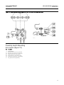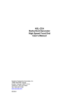
1
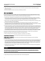
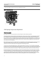
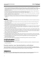
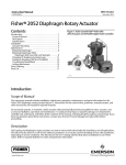
Instruction Manual 1051 and 1052 Size 33 Actuators D101322X012 September 2012 Fisherr 1051 and 1052 Size 33 Diaphragm Rotary Actuators Contents Introduction . . . . . . . . . . . . . . . . . . . . . . . . . . . . . . . . . 1 Scope of Manual . . . . . . . . . . . . . . . . . . . . . . . . . . . . . 1 Description . . . . . . . . . . . . . . . . . . . . . . . . . . . . . . . . . 2 Specifications . . . . . . . . . . . . . . . . . . . . . . . . . . . . . . . 3 Installation . . . . . . . . . . . . . . . . . . . . . . . . . . . . . . . . . . 3 Actuator Mounting and Changing Actuator Mounting . . . . . . . . . . . . . . . . . . . . . . . . . . . . . . . . 5 F and G Mounting Adaptations . . . . . . . . . . . . . 5 H Mounting Adaptation . . . . . . . . . . . . . . . . . . . 7 J Mounting Adaptation . . . . . . . . . . . . . . . . . . . . 8 1052 Spring Compression Adjustment . . . . . . . . . 10 Initial Compression . . . . . . . . . . . . . . . . . . . . . . 10 Stroking Range . . . . . . . . . . . . . . . . . . . . . . . . . 11 Maintenance . . . . . . . . . . . . . . . . . . . . . . . . . . . . . . . . 11 Mounting Adaptations . . . . . . . . . . . . . . . . . . . . . . 12 Replacing Diaphragm . . . . . . . . . . . . . . . . . . . . . . . 12 Replacing Diaphragm Plate, Diaphragm Rod, Spring, and Spring Seat . . . . . . . . . . . . . . . . . . . . 13 Changing Or Replacing Actuator Lever . . . . . . . . . 16 Proximity Switches, Lever-Operated Switches, and Positioner . . . . . . . . . . . . . . . . . . . . . . . . . . . 18 Installing the Cam . . . . . . . . . . . . . . . . . . . . . . 18 Installing Proximity Switches . . . . . . . . . . . . . . 19 Switches Indicating Bottom of Stroke . . 19 Switches Indicating Top of Stroke . . . . . . 19 Installing Lever-Operated Switch . . . . . . . . . . 19 Installing the Push Rod . . . . . . . . . . . . . . . . 20 Figure 1. Fisher 1052 Actuator with CV500 Valve and FIELDVUE™ DVC6200 Digital Valve Controller W8192-2 Mounting Lever-Operated Switch and Adjustment . . . . . . . . . . . . . . . . . . . . . . . . . . Positioner Mounting . . . . . . . . . . . . . . . . . . . . . . . . Top-Mounted Handwheel . . . . . . . . . . . . . . . . . . . . Locking Mechanism . . . . . . . . . . . . . . . . . . . . . . . . . Parts Ordering . . . . . . . . . . . . . . . . . . . . . . . . . . . . . . . Parts Kits . . . . . . . . . . . . . . . . . . . . . . . . . . . . . . . . . . . Parts List . . . . . . . . . . . . . . . . . . . . . . . . . . . . . . . . . . . 20 20 20 21 23 23 23 Introduction Scope of Manual This instruction manual includes installation, adjustment, operation, maintenance, and parts information for the Fisher 1051 and 1052 Size 33 diaphragm rotary actuators (figure 1). Mounting adaptations F, G, H, and J are included in this manual. Instructions for the control valve, positioner, manual actuator, and other accessories are included in separate manuals. www.Fisher.com Instruction Manual 1051 and 1052 Size 33 Actuators September 2012 D101322X012 Table 1. Specifications Available Configuration 1051: For on-off service without a positioner or for throttling service with a positioner 1052: For on-off service without a positioner or for throttling service with or without a positioner Standard Diaphragm Pressure Ranges J 0 to 1.2 bar (0 to 18 psig), J 0 to 2.3 bar (0 to 33 psig), J 0 to 2.8 bar (0 to 40 psig), and J 0 to 3.8 bar (0 to 55 psig) Maximum Diaphragm Sizing Pressure(1, 2) 3.8 bar (55 psig) Maximum Diaphragm Casing Pressure(1, 7) 4.5 bar (65 psig) Maximum Valve Shaft Rotation J 90 degrees (adjustable through 60 degrees with integral travel stops) Acceptable Valve Shaft Diameters, mm (Inches) F and G mounting: J 12.7 (1/2), J 15.9 (5/8), or J 19.1 (3/4) H mounting: varies–uses 22.2 mm (7/8 inch) output shaft with two flats J mounting: J 9.5 (3/8), J 12.7 (1/2), or 15.9 (5/8) Stroking Time Dependent of actuator size, rotation, spring rate, initial spring compression, supply pressure, and size of supply piping. If stroking time is critical, consult your Emerson Process Management sales office. Diaphragm Casing Displacement Clearance Volume(3): 623 cm3 (38 cubic inches) Casing Volume(4) 90 Degree Rotation: 2390 cm3 (146 cubic inches) 60 Degree Rotation: 1890 cm3 (115 cubic inches) Material Temperature Capabilities(1) NBR (nitrile) Diaphragm or O-rings(5): -40 to 82_C (-40 to 180_F) VMQ (silicone) Diaphragm: -40 to 149_C (-40 to 300_F) POM (polyoxymethylene) Push Rods and Guides (used with lever-operated switches): -40 to 82_C(6) (-40 to 180_F) Travel Indication Graduated disc and pointer Pressure Connections Standard: 1/4 NPT internal Optional: J 1/2 or J 3/4 NPT internal Mounting Positions See figure 2 Approximate Weights 1051: 20 kg (45 pounds) 1052: 21 kg (46 pounds) 1. The pressure/temperature limits in this manual and any applicable standard or code limitation for valve should not be exceeded. 2. Use this value to determine the maximum torque output allowed. 3. Volume when the diaphragm is in the up position. 4. Includes clearance volume. 5. NBR (nitrile) O-rings are used in the optional top-mounted handwheel and in the optional up travel stop assembly. 6. For higher temperature ratings, contact your Emerson Process Management sales office. 7. This maximum casing pressure is not to be used for normal operating pressure. Its purpose is to allow for typical regulator supply settings and/or relief valve tolerances. Do not install, operate, or maintain a 1051 or 1052 actuator without being fully trained and qualified in valve, actuator, and accessory installation, operation, and maintenance. To avoid personal injury or property damage, it is important to carefully read, understand, and follow all the contents of this manual, including all safety cautions and warnings. If you have any questions about these instructions, contact your Emerson Process Management sales office before proceeding. Description 1051 and 1052 Size 33 spring-and-diaphragm actuators are used on rotary-shaft valve bodies for throttling or on-off applications. The 1051 may be used for on-off service without a positioner or for throttling service with a positioner. 2 Instruction Manual 1051 and 1052 Size 33 Actuators D101322X012 September 2012 The 1052 uses an adjustable spring seat to control spring compression. It may be used for on-off service without a positioner, or it may be used for throttling service with or without a positioner, depending on service conditions. A top-mounted handwheel may be mounted for infrequent service as a manual override. A manual actuator is recommended for routine and repeated manual operation. Externally adjustable travel stops are used to limit the degree of rotation at both ends of the actuator stroke. Provisions are included for integral mounting of optional magnetic proximity switches. Lever-operated, mechanical switches are also available. The lever for the 1051 and 1052 size 33 actuator is supported by bushings. The lever may be changed to accommodate valve bodies with different size valve shafts and different mounting adaptations. Levers and accessories are available for mounting valve bodies and equipment with the following mounting adaptations: F and G mounting adaptations (figures 9 and 10) are for use with Fisher splined-shaft rotary valve bodies with 12.7, 15.9, and 19.1 mm (1/2, 5/8, and 3/4 inch) valve shaft diameters. A stub shaft is available for installation on the end of the lever opposite the valve body for use as a wrench-operated extension (for emergency override) or as a means of connecting a manual actuator (see figure 14). H mounting (figure 11) is for use with non-Fisher products and user-provided mounting brackets and shaft couplings. It includes a mounting surface with threaded holes for attaching the user-provided mounting bracket. A 22.2 mm (7/8 inch) stub shaft with flats is pinned to the lever and is used to couple the actuator to the operated equipment. A second stub shaft may be installed on the opposite end of the lever for use as a wrench-operated extension (for emergency override) or as a means for connecting a manual actuator (see figure 14). Stub shafts are available in standard and reverse constructions (see figure 12) to provide proper operation with the mounting position and actuator action desired (see figure 2). J mounting (figure 13) permits use of the actuator with Fisher keyed-shaft valve bodies and other keyed-shaft equipment with 9.5, 12.7, and 15.9 mm (3/8, 1/2, and 5/8 inch) shaft diameters. A stub shaft is pinned to the lever and a valve shaft coupling is pinned to the stub shaft. The coupling has multiple keyways (see figure 4) to accommodate mounting in the desired position. A second stub shaft may be installed on the opposite end of the lever for use as a wrench-operated extension (for emergency override) or as a means for connecting a manual actuator (see figure 14). Table 2. Bolting Torque Requirements(1) TORQUE DESCRIPTION KEY NUMBER BOLT SIZE NSm LbfSft Diaphragm Casing 5 3/8-24 27 20 Travel Stop 8 7/16-14 27 20 Diaphragm to rod 9 3/8-24 54 40 Rod end to lever 18 3/8-16 54 40 Housing to yoke 23 5/16-18 41 30 Housing to cover 34 5/16-18 41 30 Yoke to valve 71 3/8-16 (See appropriate valve instruction manual) Clamped lever 28 3/8-16 54 40 Switch Nut 78 3/8-16 27 20 1. Exceeding any torque requirements could damage the actuator and impair safe operation. Specifications Specifications are shown in table 1 for 1051 and 1052 size 33 actuators. Some specifications for a given actuator as it originally comes from the factory are stamped on a metal nameplate attached to the actuator. Installation WARNING Always wear protective gloves, clothing, and eyewear when performing any installation operations. 3 Instruction Manual 1051 and 1052 Size 33 Actuators September 2012 D101322X012 Check with your process or safety engineer for any other hazards that may be present from exposure to process media. If installing into an existing application, also refer to the WARNING at the beginning of the Maintenance section in this instruction manual. VALVE SERIES OR DESIGN MOUNTING ACTION(1) Right-Hand PDTC PDTO BALL/PLUG ROTATION TO CLOSE CCW CCW Left-Hand PDTC PDTO Left-Hand (Optional)(2) PDTC PDTO VALVE SERIES OR DESIGN V250 V150, V200 & V300 CV500 V500 A B A B A B DISC/BALL ROTATION TO CLOSE CW CW NA NA 8510B, 8532, 8560 & 9500 B A CCW CCW NA NA D C D C CW CW C D C D CW CW NA NA C D NA NA NA NA NA NA NA NA V250 1. PDTC–Push-down-to-close, and PDTO–Push-down-to-open. 2. A left hand ball will be required for the NPS 3 through 12 Series B and the NPS 14 to 20, with or without attenuator. Figure 2. Mounting Styles and Positions for Fisher 1051 and 1052 Actuators STYLE A STYLE B POSITION 1 POSITION 1 1 1 STYLE D FLOW STYLE C LEFT-HAND MOUNTING 4 2 4 2 3 3 RIGHT-HAND MOUNTING STYLE C STYLE D STYLE B STYLE A POSITION 1 POSITION 1 1 FLOW 2 4 4 43A6505-A A1584-3 4 RIGHT-HAND MOUNTING 2 3 3 LEFT-HAND MOUNTING NOTES: 1 POSITION 1 IS STANDARD; POSITIONS 2 THROUGH 4 (SHOWN IN DOTTED LINES) ARE ALTERNATIVES. 1 Instruction Manual 1051 and 1052 Size 33 Actuators D101322X012 September 2012 CAUTION To avoid parts damage, do not use an operating pressure that exceeds the Maximum Diaphragm Casing Pressure (table 1) or produces a torque greater than the Maximum Allowable Valve Shaft Torque (see Catalog 14). Use pressure-limiting or pressure-relieving devices to prevent the diaphragm casing pressure from exceeding its limit. The actuator, as it comes from the factory, is normally mounted on a valve body. Follow the procedures given in the valve instruction manual when installing the control valve in the pipeline. If a positioner is ordered with the actuator, the pressure connection to the actuator is normally made at the factory. If it is necessary to make this connection, run either 1/4 inch pipe or 3/8 inch tubing (for standard diaphragm case fittings) between the pressure connection and the instrument. Keep the length of tubing or pipe as short as possible to avoid transmission lag in the control signal. When the control valve is completely installed and connected to the controlling instrument, check to make sure that the action is correct (air-to-open or air-to-close) and that the controlling instrument is properly configured for the desired action. For successful operation, the diaphragm rod, lever, and valve shaft must move freely in response to changes in the loading pressure on the diaphragm. Actuator Mounting and Changing Actuator Mounting Use the following steps to mount the actuator or to change actuator mounting style or position. F and G Mounting Adaptations Unless otherwise specified, key numbers referenced in the following procedures are shown in figure 9 for the 1051 actuator and in figure 10 for the 1052 actuator. 1. Proceed as appropriate: If the Actuator is mounted on a valve body and it is necessary to change mounting style or position, the actuator must first be separated from the valve body. Proceed to the Disassembly portion of the Changing or Replacing Actuator Lever procedure, observe all warnings, perform steps 1 through 6, and return to step 2 which follows. If the Actuator is not mounted on a valve body, proceed to the Disassembly portion of the Changing or Replacing Actuator Lever procedure, perform steps 2 through 5, and return to step 2 which follows. 2. Refer to figure 2 for available mounting styles and positions. When mounting on a Vee-Ball™ V150, V200 or V300 valve, check the valve manual to determine if it is Series B. The actuator is normally positioned vertically with the valve in a horizontal pipeline. 3. Determine whether the actuator mounting yoke (key 22) will be mounted on the housing cover assembly (key 33) side or on the actuator housing boss side of the actuator. If the desired mounting position and style require moving the mounting yoke and travel indicator (key 35) to opposite sides of the actuator, remove the machine screws (key 38), the travel indicator pointer (key 37), the machine screws, and the travel indicator scale (key 35). Remove the cap screws (key 23) and the mounting yoke. Install the mounting yoke in the desired position (on the housing cover assembly or on the actuator housing boss). See table 2 for recommended torque for the mounting cap screws. Install the travel indicator components on the opposite side of the actuator. See figure 14 for travel indicator components used with wrench-operated extensions and manual actuators. 4. Before sliding the valve shaft into the lever, position the valve ball or disc as follows: For push-down-to-close action, the valve ball or disc should be in the fully open position. 5 Instruction Manual 1051 and 1052 Size 33 Actuators September 2012 D101322X012 For push-down-to-open action, the valve ball or disc should be in the fully closed position (see the valve body instruction manual). 5. Make sure that the index markings on the valve shaft are properly aligned with the markings on the lever and slide the valve shaft into the lever. Install the valve mounting cap screws, washers, and nuts and tighten to the torque value given in the appropriate valve body instruction manual. 6. Ensure all end play in the valve shaft is removed by pulling the valve shaft toward the actuator as much as possible. Make sure the actuator rod is perpendicular to the valve shaft. Refer to the valve instruction manual for specific end play considerations. Figure 3.Travel Stops and Switch Positions on the Fisher 1051 and 1052 Size 33 Actuator HOUSING COVER ASSEMBLY (KEY 33) YOKE MOUNTING BOSS UP TRAVEL STOP DOWN TRAVEL STOP MOUNTING POSITION FOR SWITCH INDICATING BOTTOM OF STROKE (ACTIVATED BY INNER CAM) PROXIMITY SWITCHES MOUNTING POSITION FOR SWITCH INDICATING TOP OF STROKE (ACTIVATED BY OUTER CAM) W4738 7. Tighten the socket head cap screw which compresses the splined lever connection to the valve shaft (see table 2). CAUTION When adjusting the travel stop for the closed position of the valve ball or disc, refer to the appropriate valve instruction manual for detailed procedures. Undertravel or overtravel at the closed position may result in poor valve performance and/or damage to the equipment. 8. Adjust the up travel stop (see figure 3) so that the valve ball or disc is in the desired position. WARNING To avoid personal injury and equipment damage from moving parts, keep fingers and tools clear while stroking the actuator with the cover removed. 9. Stroke the actuator and adjust the down travel stop so that the valve ball or disc is in the desired position. 6 Instruction Manual 1051 and 1052 Size 33 Actuators D101322X012 September 2012 10. Make sure that the travel indicator pointer matches the ball or disc position. Remove and install in the proper position if necessary. 11. Install the cover plate or switch mounting plate (key 59) with cap screws (key 60). 12. Refer to the table of contents for accessory installation procedures. H Mounting Adaptation Unless otherwise specified, key numbers referenced in the following procedures are shown in figure 9 for the 1051 actuator and in figure 10 for the 1052 actuator. Unique parts used for the H mounting adaptation are shown in figure 11 for single stub shaft construction and in figure 14 for dual stub shaft construction. 1. To change mounting style or position, the actuator must be separated from the valve body (or other operated equipment). Remove the cap screws used to attach the actuator to the valve body (or other operated equipment) and remove the actuator. 2. Determine the desired mounting position. Note that stub shafts are available in standard and reverse constructions so that proper alignment with the operated equipment can be achieved (see figure 12). Refer to figure 2 for available mounting styles and positions. 3. If it is necessary to install or change stub shaft(s), the actuator lever (key 27) must be removed. Perform all applicable operations in the Disassembly portion of the Changing or Replacing Actuator Lever procedure. Install the stub shafts for the construction desired (refer to figures 11 and 14) and reassemble the actuator. 4. Determine whether the operated equipment will be mounted on the housing cover assembly (key 33) side or on the actuator housing boss side of the actuator. Depending on the desired mounting style and position, it may be necessary to move the operated equipment and travel indicator components to opposite sides of the actuator. If so, remove the travel indicator components, the operated equipment, and the mounting bracket if used. Install the operated equipment or mounting bracket in the desired position (on the housing cover assembly or on the actuator housing boss). See table 2 for recommended torque for the mounting cap screws. Install the travel indicator components on the side of the actuator opposite the operated equipment. Refer to figure 14 for travel indicator components used with wrench-operated extensions and manual actuators. 5. Before coupling the operated equipment to the actuator stub shaft, position the equipment as follows: For push-down-to-activate (open) action, the equipment should be in the fully deactivated (closed) position. For push-down-to-deactivate (close) action, the equipment should be in the fully activated (open) position. 6. Install the required shaft coupling and the operated equipment. CAUTION When adjusting the travel stops to limit rotation, be certain that the rotation produced does not exceed the safe limit of the operated equipment. Undertravel or overtravel may result in poor performance and/or damage to the equipment. 7. Adjust the up travel stop (see figure 3) so that the operated equipment is in the desired position. WARNING To avoid personal injury and equipment damage from moving parts, keep fingers and tools clear while stroking the actuator with the cover removed. 8. Stroke the actuator and adjust the down travel stop so that the operated equipment is in the desired position. 7 1051 and 1052 Size 33 Actuators September 2012 Instruction Manual D101322X012 9. Make sure that the travel indicator pointer matches the ball or disc position. Remove and install in the proper position if necessary. 10. Refer to the table of contents for accessory installation procedures. J Mounting Adaptation Unless otherwise specified, key numbers referenced in the following procedures are shown in figure 9 for the 1051 actuator and in figure 10 for the 1052 actuator. Unique parts used for the J mounting adaptation are shown in figure 13 for single stub shaft construction and in figure 14 for dual stub shaft construction. 1. If the actuator is mounted on a valve body and it is necessary to change mounting style or position, the actuator must be separated from the valve body. Proceed to the disassembly portion of the Changing or Replacing Actuator Lever procedure, observe all warnings, perform steps 1 through 6, and return to step 2 which follows. 2. Refer to figure 2 for available mounting styles and positions. The actuator is normally mounted vertically on a valve body that is installed in a horizontal pipeline. 3. If it is necessary to install or change stub shaft(s), the actuator lever (key 27) must be removed. Perform all applicable operations in the Disassembly portion of the Changing or Replacing Actuator Lever procedure. Install the stub shafts for the construction desired as shown in figure 13 and reassemble the actuator. 4. Determine whether the actuator mounting yoke (key 22) will be mounted on the housing cover assembly (key 33) or on the actuator housing boss. If the desired mounting position and style requires moving the mounting yoke and travel indicator components to opposite sides of the actuator, remove the travel indicator components, the valve shaft coupling (key 80 for 1051, or key 90 for 1052), cap screws (key 23), and the mounting yoke. Install the mounting yoke in the desired position (on the housing cover assembly or on the actuator housing boss). See table 2 for recommended torque for the mounting cap screws. Install the valve shaft coupling on the actuator stub shaft. Install the travel indicator components on the opposite side of the actuator. See figure 14 for travel indicator components used with wrench-operated extensions and manual actuators. 5. Before coupling the valve to the actuator, position the valve ball or disc as follows: For push-down-to-close action, the valve ball or disc should be in the fully open position. For push-down-to-open action, the valve ball or disc should be in the fully closed position (see the valve body instruction manual). 6. The valve shaft coupling (see figure 4) has two keyways lettered A and B (the letters C and D on the coupling are not used and may be disregarded). Align the appropriate keyway with the keyway in shaft of the operated equipment. When used with a Fisher butterfly valve body, refer to the table and illustration in figure 4 for proper orientation of the coupling and valve shaft. Install the woodruff key (key 81 for 1051, key 91 for 1052) in the valve shaft keyseat, lubricate the inside of the coupling, and slide the valve shaft into the coupling. 7. Install the valve mounting cap screws, washers, and nuts and tighten to the torque value given in the appropriate valve body instruction manual. CAUTION When adjusting the travel stop for the closed position of the valve ball or disc, refer to the appropriate valve body instruction manual for detailed procedures. Undertravel or overtravel at the closed position may result in poor valve performance and/or damage to the equipment. 8. Adjust the up travel stop so that the valve ball or disc is in the desired position. 8 Instruction Manual 1051 and 1052 Size 33 Actuators D101322X012 September 2012 DESIRED SHAFT ROTATION, DEGREES DESIRED ACTUATOR ACTION Push Down to Open (PDTO) Push Down to Close (PDTC) ACTUATOR MOUNTING POSITION 60 or 90 60(3) or 90 COUPLING KEYWAY TO USE(3) VALVE SHAFT KEYWAY TO USE FOR FISHTAIL™ DISC VALVE BODIES(1) (SEE FIGURE 2) Clockwise to Counterclockwise to Close Valve Action(2) Close Valve Action(2) Flow Left Flow Right Flow Left Flow Right to Right(2) to Left(2) to Right(2) to Left(2) Nose Tail Tail Nose 1 B 2 A Tail Nose Nose 3 B Tail Nose Nose Tail 4 A Nose Tail Tail Nose 1 A Tail Nose Tail Nose 2 B Tail Nose Tail Nose 3 A Nose Tail Nose Tail 4 B Nose Tail Nose Tail Tail 1. For conventional disc valve bodies, use either valve shaft keyway. 2. When viewed from actuator side of valve body. 3. For 60-degree rotation with PDTC action, the coupling and actuator output shaft assembly will offset 30 degrees clockwise (for actuator housing construction style B), or counterclock wise (for actuator housing construction Style A) in the lever when viewed from the splined end of the actuator shaft. 30 degrees is one spline tooth for 9.5, 12.7, and 15.9 mm (3/8, 1/2, and 5/8 inch) valve shafts and two spline teeth for 19.1 mm (3/4 inch) valve shafts. Figure 4. Valve Shaft Coupling for the J Mounting Adaptation 1 COUPLING FULL KEYWAY LOCATED ON NOSE AND TAIL SIDE OF VALVE SHAFT VALVE SHAFT USE APPROPRIATE LETTERED KEYWAY AS INDICATED IN TABLE 5 PARTIAL KEYWAY FOR DETERMINING DISC POSITION KEYWAY A USE APPROPRIATE VALVE SHAFT KEYWAY AS INDICATED IN TABLE 5 KEYWAY B ABOVE KEYWAY A EXPLODED VIEW OF VALVE SHAFT AND COUPLING 19A1465-B NOTES: 1 FOR USE WITH J MOUNTING ADAPTATION. REFERENCE COUPLING ORIENTATION FOR TABLE 5 A3253* WARNING To avoid personal injury and equipment damage from moving parts, keep fingers and tools clear while stroking the actuator with the cover removed. 9. Stroke the actuator and adjust the down travel stop so that the valve ball or disc is in the desired position. 10. Make sure that the travel indicator pointer matches the ball or disc position. Remove and install in the proper position if necessary. 9 Instruction Manual 1051 and 1052 Size 33 Actuators September 2012 D101322X012 11. Refer to the table of contents for accessory installation procedures. Figure 5. Spring Adjustment TRAVEL STOPS W4767 1052 Spring Compression Adjustment Initial Compression Key numbers referred to in this procedure are shown in figure 10 unless otherwise specified. The 1052 nameplate specifies an initial set adjusted into the actuator spring. Initial set is the casing pressure at which the diaphragm (key 3) and diaphragm rod (key 10) begin to move away from the stop in the upper diaphragm case (key 1) when the actuator is disengaged from the control valve body or other operated equipment. The initial set was determined from the service conditions specified when the actuator was ordered, so that when the actuator and valve are in service, the valve ball or disc seats properly and full travel is obtained with the supply pressure specified on the order and shown on the nameplate. Before adjusting spring tension to change initial set, the valve body or other operated equipment must be removed or otherwise disengaged from the actuator. Refer to the applicable steps given under the appropriate mounting adaptation in the Actuator Mounting and Changing Actuator Mounting procedure. To gain access to the spring adjusting screw, either the spring adjuster cover (key 117) or the switch mounting plate (key 59) must be removed. If externally mounted switches are used, remove them as an assembly by removing the cap screws (key 75, figure 16) and the switch mounting plate (key 1, figure 16). In order to gain access to the cap screws, it may be necessary to loosen the hex nuts (key 77, figure 16) and slide the switches away from the actuator housing. Note that the lower part of the spring adjusting screw (key 74) is notched so that it can be rotated with a screwdriver or other flat-bladed tool. To decrease spring compression, rotate the spring adjusting screw to the right (see figure 5). To increase spring compression, rotate the spring adjusting screw to the left (clockwise when viewed from above). Adjust the spring so that the diaphragm rod just starts to travel at the initial set pressure specified on the nameplate. When the desired initial set has been achieved, install the spring adjuster cover or switch mounting plate. 10 Instruction Manual 1051 and 1052 Size 33 Actuators D101322X012 September 2012 Table 3. Spring for Fisher 1052 Actuator(1) CASING PRESSURE Bar 0-1.2 0-2.3 0-2.8 Psig 0-18 0-33 0-40 0-3.8 0-55 0.2-1 3-15 0.2-2.1 3-30 INITIAL SPRING COMPRESSION 60 Degree Rotation Push-down-to-open 90 Degree Rotation Push-down-to-open Push-down-to-close Bar Psig Bar Psig Bar Psig 0.3 3.9 0.2 2.7 0.2 2.7 0.4 5.4 0.3 3.7 0.2 3 0.4 6.1 0.3 4.9 0.2 3 0.3 3.9 --- --- 0.2 2.7 0.4 5.4 0.3 3.7 0.3 3.7 0.5 7.1 0.3 4.9 0.3 4.9 0.7 9.7 0.4 6.3 0.2 3 0.3 3.9 --- --- 0.2 2.7 0.4 5.4 0.3 3.7 0.3 3.7 0.5 7.1 0.3 4.9 0.3 4.9 0.7 9.7 0.4 6.3 0.2 3.5 --- --- 0.3 4.9 0.3 4.9 0.7 9.7 0.4 6.3 0.4 6.3 --- --- 0.3 3.7 0.2 3 --- --- --- --- 0.3 3.7 --- --- 0.3 4.9 0.3 4.9 --- --- 0.4 6.3 0.2 3 1. For more detailed information concerning proper spring selection to obtain the torque required, consult your Emerson Process Management sales office. Stroking Range Key numbers referred to in this procedure are shown in figure 10 unless otherwise specified. If, under operating conditions, the desired stroking range cannot be achieved with the casing pressure used, it may be possible to shift the stroking range by making a spring adjustment to change the initial spring compression. A spring adjustment shifts the casing pressure span and equally increases (or decreases) the casing pressure at which the actuator begins to stroke and the pressure at which the actuator reaches full travel. To gain access to the spring adjusting screw, either the spring adjuster cover (key 117) or the switch mounting plate (key 59) must be removed. If externally mounted switches are used, remove them as an assembly by removing the cap screws (key 75, figure 16) and the switch mounting plate (key 1, figure 16). In order to gain access to the cap screws, it may be necessary to loosen the hex nuts (key 77, figure 16) and slide the switches away from the actuator housing. Note that the lower part of the spring adjusting screw (key 74) is notched so that it can be rotated with a screwdriver or other flat bladed tool. To shift the casing pressure span downward, rotate the spring adjusting screw to the right (see figure 5). To shift the casing pressure span upward, rotate the spring adjusting screw to the left. When the desired stroking range has been achieved, replace the spring adjuster cover or the switch mounting plate. Maintenance Actuator parts are subject to normal wear and must be inspected and replaced as necessary. The frequency of inspection and replacement depends upon the severity of service conditions. Instructions are given below for disassembly and assembly of parts. Key numbers referenced in the following steps are shown in figure 9 for the 1051 actuator and in figure 10 for the 1052, except as listed below or otherwise specified in the procedures. 11 1051 and 1052 Size 33 Actuators Instruction Manual September 2012 D101322X012 Mounting Adaptations F and G Adaptations The procedures given in this instruction manual apply directly to F and G mounting adaptations. Refer to figures 9 and 10. H Mounting Adaptations Whenever the procedures require separating the actuator from the operated equipment, it may be necessary to remove brackets, couplings, and stub shafts before proceeding. Refer to figure 11 for parts used with the H mounting adaptation. J Mounting Adaptations Whenever the procedures require separating the actuator from the valve body, it may be necessary to remove couplings and keyways. Refer to figure 13 for parts used with the J mounting adaptation. WARNING Avoid personal injury or property damage from sudden release of process pressure or bursting of parts. Before performing any maintenance operations: D Do not remove the actuator from the valve while the valve is still pressurized. D Always wear protective gloves, clothing, and eyewear when performing any maintenance operations. D Disconnect any operating lines providing air pressure, electric power, or a control signal to the actuator. Be sure the actuator cannot suddenly open or close the valve. D Use bypass valves or completely shut off the process to isolate the valve from process pressure. Relieve process pressure from both sides of the valve. Drain the process media from both sides of the valve. D Vent the power actuator loading pressure and relieve any actuator spring precompression. D Use lock-out procedures to be sure that the above measures stay in effect while you work on the equipment. D The valve packing box may contain process fluids that are pressurized, even when the valve has been removed from the pipeline. Process fluids may spray out under pressure when removing the packing hardware or packing rings. D Check with your process or safety engineer for any hazards that may be present from exposure to process media. Replacing Diaphragm Disassembly 1. Bypass the control valve. Relieve all loading pressure, and remove the tubing or pipe from the upper diaphragm case (key 1). 2. Observe the position of the travel indicator pointer (key 37) and mark its position on the travel indicator scale (key 35). WARNING Failure to control spring tension against the upper diaphragm case as outlined in the following step could result in sudden spring decompression causing bodily injury or equipment damage. Control spring tension by following step 3 closely. 12 Instruction Manual 1051 and 1052 Size 33 Actuators D101322X012 September 2012 3. Loosen the hex jam nut (key 84 for 1051, or key 86 for 1052) on the up travel stop. This stop is nearest to the positioner or positioner cover (key 39; also see figure 3). Screw the travel stop in (turn it clockwise) until it can be verified that all spring tension has been removed from the diaphragm stop in the upper diaphragm case, i.e. when any movement of the travel indicator pointer is observed, all spring tension against the upper diaphragm case stop has been removed. Do not rotate the travel stop past this position as additional compression of the spring is not necessary or desirable. 4. Carefully remove all cap screws and hex nuts (keys 5 and 6) from the diaphragm case. 5. Remove the diaphragm case and the diaphragm (key 3). 6. Inspect the diaphragm plate (key 4). If the diaphragm plate is damaged or if further disassembly of the actuator is required, proceed to the Diaphragm Plate, Diaphragm Rod, Spring, and Spring Seat procedure. 7. Inspect the diaphragm and replace if necessary. Assembly 1. Place the diaphragm (key 3) on the diaphragm plate (key 4), making certain that it is properly centered. 2. Make sure that the up travel stop (see figure 3) is screwed in sufficiently to eliminate interference of the diaphragm plate (key 4) with the upper diaphragm case. 3. Observe the correct position of the loading connection fitting and install the upper diaphragm case (key 1). Replace the cap screws and nuts (keys 5 and 6) which secure the upper diaphragm case to the actuator housing. Tighten the nuts in an alternating fashion (see table 2). CAUTION When adjusting the travel stop for the closed position of the valve ball or disc, refer to the appropriate valve body instruction manual for detailed procedures. Undertravel or overtravel of many valve types may result in poor valve performance and/or damage to the equipment. 4. Adjust the up travel stop (see figure 3). If the upper travel stop establishes the closed position of the valve ball or disc, refer to the valve body instruction manual and follow the procedures given for properly establishing the closed position. Proceed as appropriate: For F, G, and J mounting adaptations, perform operations beginning with step 8 under the appropriate mounting adaptation section of the Actuator Mounting and Changing Actuator Mounting procedure. For H mounting adaptations, perform operations beginning with step 7 under the appropriate mounting adaptation section of the Actuator Mounting and Changing Actuator Mounting procedure. 5. Return the travel indicator pointer to its original position as previously marked on the travel indicator scale. 6. Install the inlet piping to the upper diaphragm case. Replacing Diaphragm Plate, Diaphragm Rod, Spring, and Spring Set Disassembly 1. Perform steps 1 through 6 of the Disassembly portion of the Replacing Diaphragm procedure above. For 1052 Actuators Only a. Before removing the diaphragm plate, spring compression must be relieved. Proceed as appropriate to gain access to the spring adjusting screw: 13 1051 and 1052 Size 33 Actuators Instruction Manual September 2012 D101322X012 D Without lever-operated switches, remove the cap screws (key 21) and the spring adjuster cover (key 117). D With lever-operated switches, remove the switches as an assembly by removing the cap screws (key 75, figure 16) and the switch mounting plate (key 1, figure 16). In order to gain access to the cap screws, it may be necessary to loosen the hex nuts (key 77, figure 16) and slide the switches away from the actuator housing. WARNING To avoid personal injury from precompressed spring force suddenly thrusting parts away from the actuator, spring compression must first be relieved by rotating the spring adjusting screw until the spring seat is bottomed against the spring adjuster. Closely follow the instructions below. b. To relieve spring compression, insert a screwdriver into the notches on the spring adjusting screw and rotate the spring adjusting screw to the right (counter-clockwise when viewed from the top of the actuator) until the spring seat (key 13) is bottomed against the spring adjuster. 2. For 1051 and 1052 Actuators, using a 5/16 inch hex wrench, unscrew and remove the socket head cap screw (key 9) which secures the diaphragm plate (key 4) to the diaphragm rod (key 10). Remove the diaphragm plate and the upper thrust washer (key 83 for 1051, or key 72 for 1052). 3. For the 1051, remove the spring (key 11) and spring seat (key 14). For the 1052, remove the spring (key 11), spring seat with adjusting screw (keys 74 and 14), and lower thrust washer (key 72). Note At this stage of disassembly, it may be determined that further disassembly is not necessary. If separation of the diaphragm rod from the lever is not warranted, proceed to the Assembly portion of this procedure. 4. To gain access to the cap screw (key 18) which secures the diaphragm rod to the lever, the housing cover assembly (key 33) must be removed. Before the housing cover assembly can be removed, one of the following procedures must be performed. Proceed as appropriate: For actuators with valve bodies mounted on the housing cover assembly (key 33) side of the actuator, the actuator must be separated from the valve body to provide access to the cap screw (key 18). Proceed to the Disassembly portion of the Changing or Replacing Actuator Lever procedure and perform steps 2 through 6. For actuators with valve bodies mounted on the actuator housing boss side of the actuator, remove the travel indicator pointer (key 37). 5. Remove the cap screws and washers (keys 34 and 63) and the housing cover assembly (key 33). 6. Remove the outer switch cam, if used, by removing the two hex head machine screws, spacers, and retaining washers (keys 119, 132, and 144, figures 15 and 16). Note that the retaining washers help to keep all parts together as an assembly. 7. Remove the cap screw (key 18) that secures the actuator lever (key 27) to the diaphragm rod. Remove the diaphragm rod. 8. Inspect all parts and replace if necessary. 9. If total disassembly of the actuator is required, or if the actuator will be assembled for use with a valve body with a different valve shaft diameter, proceed to the Changing or Replacing Actuator Lever procedure. 14 Instruction Manual 1051 and 1052 Size 33 Actuators D101322X012 September 2012 SPRING NO. DIMENSION A mm Inches 10B1522 42.7 1.68 10B1523 42.7 1.68 10B1524 42.7 1.68 10B1525 36.6 1.44 Figure 6. Spring Seat Pre-Set Dimensions for the Fisher 1052 Size 33 Actuator A 10B1601-A A3777 Assembly For the 1052 Only a. Lubricate the threads of the spring adjusting screw (key 74) with lithium grease. Also lubricate the bottom portion of the spring adjusting screw which contacts the lower thrust washer (key 72). b. Screw the spring adjusting screw onto the spring seat (key 14) to minimize spring seat adjustment after assembly, refer to figure 6 and pre-set the spring adjusting screw to the appropriate dimension. c. Place the lower thrust washer into the lower spring barrel area. For 1051 and 1052 1. Lubricate the threads of the socket head cap screw (key 9) with lithium grease. Also lubricate the bottom surface of the diaphragm plate which contacts the upper thrust washer (key 83 for 1051, or key 72 for 1052). 2. Insert the socket head cap screw through the diaphragm plate (key 4) and into the diaphragm rod (key 10). Tighten the cap screw four or five turns. 3. Install the spring seat (with spring adjusting screw for the 1052 actuator), spring, and upper thrust washer. 4. Insert the diaphragm plate/diaphragm rod assembly into the spring barrel. Make sure that the notch in the diaphragm rod is oriented according to the view shown in figures 9 and 10, i.e. the notch in the diaphragm rod must face the positioner or positioner cover plate (key 39). 5. Rotate the lever so that it straddles the spherical bearing in the diaphragm rod. It may be necessary to exert lateral pressure on the diaphragm rod to achieve alignment of the rod with the lever. Install the cap screw (key 18) (see table 2). Use the up travel stop (see figure 3) to keep the lever from rotating during tightening. 6. If the actuator uses an outer switch cam, install the outer cam (key 170, figures 15 and 16) using the two hex head machine screws, spacers, and retaining washers (keys 119, 132, and 144). Note that the retaining washers help to keep all parts together as an assembly to ease installation. Make sure that the cam is mounted on the lever according to the orientation shown in figure 7. 15 Instruction Manual 1051 and 1052 Size 33 Actuators September 2012 D101322X012 Figure 7. Orientation of Switch and Positioner Cams on the Lever of the Fisher 1051 and 1052 Size 33 Actuator POSITIONER CAM INNER SWITCH CAM (ACTIVATES SWITCH INDICATING BOTTOM OF STROKE) W4767 SPACERS (KEY 132) OUTER SWITCH CAM (ACTIVATES SWITCH INDICATING TOP OF STROKE) 7. Install the housing cover assembly (key 33) with cap screws and washers (keys 34 and 63). 8. Tighten the socket head cap screw (key 9) with a 5/16 hex wrench until the diaphragm plate is fully seated against the diaphragm rod. Tighten the cap screw to the torque value in table 2. 9. Perform steps 1 through 5 of the Assembly portion of the Replacing Diaphragm procedure. 10. For 1052 actuators, refer to the 1052 Spring Compression Adjustment procedure and adjust the spring for the desired initial set. 11. Install the cover plate or switch mounting plate (key 59) with cap screws (key 60). If switches are used, observe the marks made during removal of the cover plate. 12. Install the spring adjuster cover (key 117) or the switch mounting plate (key 1, figure 16) with the appropriate cap screws. 13. Install the travel indicator (key 37) if removed. 14. If the actuator was removed from the valve body, refer to the appropriate section in the Actuator Mounting and Changing Actuator Mounting procedure and proceed as follows: For F and G mounting adaptations, perform all applicable steps beginning with step 3. For H and J mounting adaptations, perform all applicable steps beginning with step 4. Changing or Replacing Actuator Lever Note The lever and associated parts may be removed as an independent procedure without disassembling the upper diaphragm casing or spring barrel components. Or, the lever may be removed after performing the operations given in the Replacing Diaphragm procedure and in the Diaphragm Plate, Diaphragm Rod, Spring, and Spring Seat procedure. 16 Instruction Manual 1051 and 1052 Size 33 Actuators D101322X012 September 2012 Disassembly WARNING Avoid personal injury or property damage from sudden release of process pressure or bursting of parts. Before performing any maintenance operations: D Do not remove the actuator from the valve while the valve is still pressurized. D Always wear protective gloves, clothing, and eyewear when performing any maintenance operations. D Disconnect any operating lines providing air pressure, electric power, or a control signal to the actuator. Be sure the actuator cannot suddenly open or close the valve. D Use bypass valves or completely shut off the process to isolate the valve from process pressure. Relieve process pressure from both sides of the valve. Drain the process media from both sides of the valve. D Vent the power actuator loading pressure and relieve any actuator spring precompression. D Use lock-out procedures to be sure that the above measures stay in effect while you work on the equipment. D The valve packing box may contain process fluids that are pressurized, even when the valve has been removed from the pipeline. Process fluids may spray out under pressure when removing the packing hardware or packing rings. D Check with your process or safety engineer for any other hazards that may be present from exposure to process media. 1. Isolate the valve body from the process. Release process pressure and vent all actuator pressure. 2. If externally mounted switches are used, remove them as an assembly by removing the cap screws (key 75, figure 16) and the switch mounting plate (key 1, figure 16). In order to gain access to the cap screws, it may be necessary to loosen the hex nuts (key 77, figure 16) and slide the switches away from the actuator housing. 3. If switches are used, mark the position of the switch mounting plate (key 59) on the actuator housing so it may be returned to the exact same position. 4. Remove the cap screws (key 60) and the cover plate or switch mounting plate (key 59). If switches are used, leave the push rod assemblies (keys 169 and 170, figure 16) or the proximity switch assemblies (key 7, figure 15) undisturbed. 5. Using a 5/16 inch hex wrench, loosen the socket head cap screw (key 28) which compresses the splined lever connection around the valve shaft. 6. Separate the actuator from the valve body by removing the cap screws and washers which secure the valve to the mounting yoke (key 22). For some constructions of H and J mounting adaptations, it may be necessary to remove other mounting and coupling parts. 7. If the valve body (or other operated equipment) is mounted on the housing cover (key 33) side of the actuator, remove the mounting yoke and travel indicator pointer. 8. Remove the cap screws and washers (keys 34 and 63) and the housing cover (key 33). 9. If the actuator is equipped with a positioner, remove the positioner cam (see figure 7) by removing the two hex head machine screws which secure the cam to the lever. 10. If the actuator is equipped with cam-operated switches, remove the outer cam (see figure 7) with the two hex head machine screws, spacers, and retaining washers (keys 119, 132, and 144, figures 15 and 16). Note that the retaining washers help to keep all parts together as an assembly. WARNING Failure to relieve spring tension on the diaphragm rod to lever connection before removing the cap screw (key 18) may result in personal injury and equipment damage from sudden and forceful movement of the diaphragm rod. Relieve spring tension by performing the operations described in the next step. 17 1051 and 1052 Size 33 Actuators Instruction Manual September 2012 D101322X012 11. Relieve all spring loading on the diaphragm rod (key 10) to lever (key 27) connection by backing out (turning counter-clockwise) the up position travel stop (see figure 3). When the travel stop is no longer in direct contact with the lever (key 27), it can be determined that all spring compression is being contained by the stop in the upper diaphragm case (key 1). 12. Remove the cap screw (key 18) which secures the diaphragm rod (key 10) to the lever (key 27). Disconnect the lever from the diaphragm rod by rotating the lever away from the diaphragm rod. 13. Remove and inspect the lever. If the lever is worn or damaged, or if the actuator will be mounted to a valve body requiring a different size lever, replace the lever. 14. Inspect the bushings (key 31). If bushings are excessively worn or damaged, remove them with a press. Press in new bushings so that they are flush with the interior surfaces of the actuator housing boss and housing cover assembly. Assembly 1. Refer to figure 7 for the correct orientation of the inner switch cam (if used); be sure that it is attached to the lever in the proper orientation. 2. Refer to figure 7 for the correct orientation of the lever during assembly. Insert the lever into the bushing in the actuator housing boss. 3. If the diaphragm rod has been removed, perform all operations through step 3 of the Assembly portion of the Diaphragm Plate, Diaphragm Rod, Spring and Spring Seat procedure. 4. Rotate the lever so that it straddles the spherical bearing in the diaphragm rod. It may be necessary to exert lateral pressure on the diaphragm rod to achieve alignment of the rod with the lever. Install the cap screw (key 18) and tighten to the torque value in table 2. 5. If an outer switch cam is used, install the cam using the two machine screws, spacers, and retaining washers. Note that the retaining washers help to keep all parts together as an assembly. Observe the orientation shown in figure 7. 6. If a positioner is used, install the positioner cam with machine screws. Be sure to observe the orientation shown in figure 7 and follow all procedures given in the positioner instruction manual. 7. Install the housing cover assembly (key 33). 8. If the diaphragm plate has been removed, tighten the socket head cap screw (key 9) with a 5/16 hex wrench until the diaphragm plate is fully seated against the diaphragm rod. Tighten the cap screw to the torque value in table 2. 9. If the upper diaphragm case has been removed, perform all applicable steps in the Assembly portion of the Replacing Diaphragm procedure. 10. Refer to the Actuator Mounting and Changing Actuator Mounting procedure and proceed as follows: For F and G mounting adaptations, start with step 3. For H and J mounting adaptations, start with step 4. 11. For 1052 actuators only, refer to the 1052 Spring Compression Adjustment procedure and adjust the spring for the desired initial set. Proximity Switches, Lever Operated Switches, and Positioner The proximity switches (see figure 15), lever operated switches (see figure 16), and positioner used with 1051 and 1052 size 33 actuator use cams (see figure 7) mounted on the lever to transmit valve ball or disc position feedback to the accessories. These cams must be attached to the lever before accessories can be installed. Installing the Cam Key numbers referred to in the following procedures are shown in figure 15 for proximity switch installation and in figure 16 for lever operated switch installation unless otherwise specified. Proceed as appropriate: 18 Instruction Manual 1051 and 1052 Size 33 Actuators D101322X012 September 2012 For switches which activate at the bottom of the actuator stroke, the inner cam (key 170; also see figure 7) is used. Installation of the inner cam requires removal of the actuator lever (key 27, figures 9 and 10). To remove the lever, refer to the Changing or Replacing Actuator Lever procedure and perform all applicable steps in the Disassembly portion. Install the inner cam with machine screws and retaining washers (keys 117 and 144). Note that the retaining washers help to keep all parts together as an assembly to ease installation. Reassemble the actuator and install the actuator on the valve body. For switches which activate at the top of the actuator stroke, the outer cam (key 170; also see figure 7) is used. If the valve body or other operated equipment is mounted on the housing cover assembly side of the actuator, it will be necessary to remove the valve body and the mounting yoke. Refer to the Changing or Replacing Actuator Lever procedure and perform all applicable steps in the Disassembly portion. Remove the housing cover assembly (key 33). Install the outer cam with machine screws, spacers, and retaining washers (keys 119, 132, and 144). Note that the retaining washers help to keep all parts together as an assembly to ease installation. Follow the steps in the Installation section to reassemble the actuator and install the actuator on the valve body. For actuators using a positioner, the positioner cam (see figure 7) must be installed on the lever. If the valve body or other operated equipment is mounted on the housing cover assembly side of the actuator, it will be necessary to remove the valve body and the mounting yoke. Refer to the Changing or Replacing Actuator Lever procedure and perform all applicable steps in the Disassembly portion. Remove the housing cover assembly (key 33). Install the cam on the lever with machine screws in the orientation shown in figure 7 and in the positioner instruction manual. Follow the steps in the Installation section to reassemble the actuator and install the actuator on the valve body. Installing Proximity Switches Key numbers referenced in the following procedures are shown in figure 15 unless otherwise specified. Switches Indicating Bottom of Stroke 1. Apply inlet pressure to the diaphragm case (key 1, figures 9 and 10) until the actuator is at the bottom of its stroke. Make sure that the lever (key 27, figures 9 and 10) is against the down position travel stop (see figure 3). 2. Install one 5/8 inch UNF jam nut (key 78) onto the proximity switch (key 7). Screw the switch assembly into the mounting cover (key 59, figures 9 and 10) so that it is directly over the inner cam (refer to figure 3). 3. Carefully screw the switch into the mounting cover until the electrical contacts close. Maintain a minimum of 0.5 mm (0.02 inch) clearance between the switch and the cam. 4. Lock the switch in place by tightening the locknut (key 78) to the torque value in table 2. When tightening the locknut, be careful not to turn the switch and thereby reduce its clearance with the cam. Switches Indicating Top of Stroke 1. Make sure that the air supply to the diaphragm case (key 1, figures 9 and 10) is totally vented and the lever (key 27, figures 9 and 10) is against the up position travel stop (see figure 3). 2. Install one 5/8 inch UNF jam nut (key 78) onto the proximity switch (key 7). Screw the switch assembly into the mounting cover (key 59, figures 9 and 10) so that it is directly over the outer cam (refer to figure 3). 3. Carefully screw the switch into the mounting cover until the electrical contacts close. Maintain a minimum of 0.5 mm (0.02 inch) clearance between the switch and the cam. 4. Lock the switch in place by tightening the locknut (key 78) to the torque value in table 2. When tightening the locknut, be careful not to turn the switch and thereby reduce its clearance with the cam. Installing Lever-Operated Switch Refer to figure 16 for the key numbers referenced in the following procedures and for proper orientation of switches and switch mounting accessories. 19 1051 and 1052 Size 33 Actuators Instruction Manual September 2012 D101322X012 Installing the Push Rod 1. For Switches Indicating Bottom of Stroke, apply inlet pressure to the diaphragm case (key 1, figures 9 and 10) until the actuator is at the bottom of its stroke. Make sure that the lever (key 27, figures 9 and 10) is against the down position travel stop (see figure 3). For Switches Indicating Top of Stroke, make sure that the air supply to the diaphragm case (key 1, figures 9 and 10) is totally vented and the lever (key 27, figures 9 and 10) is against the up position travel stop (key 8, figures 9 and 10). 2. For Switches Indicating Bottom of Stroke, install one jam nut (key 78) onto the push rod guide (key 169). Refer to figure 3 and screw the push rod guide into the mounting cover (key 59, figures 9 and 10) so that it is directly over the inner cam. For Switches Indicating Top of Stroke, install one jam nut (key 78) onto the push rod guide (key 169). Screw the push rod guide into the mounting cover (key 59, figures 9 and 10) so that it is directly over the outer cam (refer to figure 3). 3. For both kinds of switches, insert the push rod (key 168) into the push rod guide with its head resting against the outer surface of the push rod guide. 4. Screw the push rod guide/push rod assembly in until the push rod contacts the cam (key 170). 5. Hold the push rod tightly against the push rod guide and screw the push rod guide into the mounting cover until a gap of 6.4 to 6.8 mm (0.25 to 0.27 inch) exists between the push rod head and the surface of the push rod guide. 6. Lock the push rod guide in place by tightening the locknut to the torque value in table 2. Be careful not to turn the push rod guide and thereby reduce its clearance with the push rod head. 7. Install the boot (key 163) over the push rod and the push rod guide. Mounting Lever-Operated Switch and Adjustment 1. If used, remove the cap screws and spring adjuster cover (keys 21 and 85 for 1051, or keys 21 and 117 for 1052). 2. Attach the switch mounting plate (key 1) at this location with cap screws (key 75). Tighten the cap screws to the torque value in table 2. 3. Install the levers onto the switch shafts so that they are parallel to the centerline of the switch when they trip. 4. Insert the round head carriage bolts (key 4) into the switch mounting bracket (key 129). Mount the limit switch onto the bracket using machine screws and nuts (keys 8 and 9). Tighten the machine screws to 2.8 NSm (5 lbfSft). 5. Attach the switch/mounting bracket assembly to the mounting plate using the nuts and washers (keys 77 and 154). 6. Adjust the switch lever on the shaft so that its roller is in the approximate center of the push rod. 7. With the actuator set at one end of its travel, slide the appropriate switch/bracket assembly toward the actuator until the roller on the switch lever is in contact with the push rod head and the switch contacts close. Stroke the actuator to the opposite end of its travel and repeat the adjustment procedure for the other switch. Positioner Mounting 1. Before installing the positioner, the positioner cam must be installed on the lever (key 10, figures 9 and 10). Refer to the Installing the Cam procedure. 2. Refer to the positioner instruction manual for setup and calibration procedures. Top-Mounted Handwheel Key numbers used in this procedure are shown in figure 17 except where indicated. The optional top-mounted handwheel can be used as a manual actuator for intermittent service or as an adjustable up travel stop to limit full retraction of the diaphragm rod (key 10, figures 9 and 10). 20 Instruction Manual D101322X012 1051 and 1052 Size 33 Actuators September 2012 The handwheel assembly is attached to a special upper diaphragm casing (key 1, figures 9 and 10) with cap screws (key 141). A hex nut (key 137) locks the handwheel in position. For field installation of a handwheel, the special upper diaphragm case must be ordered as well as the handwheel. Turning the handwheel (key 51) clockwise into the upper casing forces the pusher plate (key 135) against the diaphragm and diaphragm plate (keys 3 and 4) to compress the spring (key 11, figures 9 and 10) and move the diaphragm rod downward. Turning the handwheel counter-clockwise allows the actuator spring to move the diaphragm rod upward. If the valve is push-down-to-close, full opening can be restricted by positioning the handwheel at the desired position. If the valve is push-down-to-open, full closing of the valve ball or disc can be restricted by use of the handwheel. Instructions are given below for complete disassembly and assembly required for inspection and parts replacement. Disassembly WARNING To avoid personal injury from the precompressed spring force thrusting the upper diaphragm casing away from the actuator, relieve spring compression before diaphragm casing bolting is loosened. 1. Remove the upper diaphragm casing (key 1, figures 9 and 10) by following steps 1 through 5 of the disassembly portion of the Replacing Diaphragm procedure. 2. Remove the cotter pin, hex nut, handwheel, and locknut (keys 247, 54, 51, and 137). Unscrew the stem (key 133) out through the actuator end of the handwheel body (key 142). 3. Remove cap screws (key 141), and separate the handwheel assembly from the upper casing. 4. Check the condition of the O-rings (keys 138 and 139); replace them if necessary. 5. If it is necessary to remove the pusher plate or spacer (key 135 or 171), drive out the groove pin (key 140). Assembly 1. Before assembling, lubricate the thread of the stem (key 133) with anti-seize lubricant (key 244). Lubricate the bearing surfaces of the stem and pusher plate (key 135) with lithium grease (key 241). 2. If the pusher plate or spacer was removed, attach them to the stem and drive in a new groove pin (key 140). 3. With the O-ring (key 138) in place, thread the stem into the handwheel assembly. 4. Attach the handwheel assembly to the upper diaphragm casing (key 1, figures 9 and 10) with cap screws (key 141). 5. Install the locknut, handwheel, hex nut, and cotter pin (keys 137, 51, 54, and 247). 6. Install the diaphragm casing, making certain the warning tag is in place on the casing flange. 7. Tighten the cap screws (key 5, figures 9 and 10) evenly in a crisscross pattern (see table 2). 8. Adjust the initial set as described in the Spring Compression Adjustment procedure. Locking Mechanism Installing the Locking Mechanism WARNING To avoid personal injury, perform the steps in the WARNING at the beginning of the Maintenance section to isolate the control valve and actuator. 21 Instruction Manual 1051 and 1052 Size 33 Actuators September 2012 D101322X012 Figure 8. Fisher 1051 and 1052 Actuator Locking Mechanism CAP SCREW (KEY 21) MOUNTING PLATE (KEY 123) MOUNTING PLATE ASSEMBLY (KEY 124) COVER (KEY 59) JAM NUT (KEY 128) PADLOCK (CUSTOMER SUPPLIED) CAP SCREW (KEY 60) GROOVE PIN (KEY 127) 24B0391-A A6226 To add the locking mechanism to an existing actuator, purchase the required parts from Emerson Process Management. 1. Remove cap screws, spring adjustor cover, and cover plate (keys 21 and 60, 85 or 117, and 59). 2. Thread jam nut (key 128) all the way onto the threaded bolt portion of the locking device before threading it into the cover (key 59). 3. After the bolt is threaded into the cover, drive the groove pin (key 127) into the threaded bolt. So the locking mechanism will not interfere with rotation of the lever (key 27), rotate the locking mechanism counterclockwise until it is stopped by the groove pin (key 127). Attach the cover to the actuator with cap screws (key 60). 4. Attach mounting plate (key 123) with cap screws (key 21). 5. Be sure the diaphragm rod is retracted fully. This will be the locked position of the valve. 6. Screw the threaded bolt into the cover until it contacts the actuator lever. 7. Rotate the locking device slightly until the hole in the mounting plate (key 123) aligns with a hole in the locking device. 8. Tighten the jam nut against the cover. 9. Insert the padlock (not furnished by Emerson Process Management) to connect the mounting plate with the locking device. Operating the Locking Mechanism To Unlock the Actuator 1. Remove the padlock. Loosen the jam nut (key 128), and unscrew the threaded bolt until it is stopped by the groove pin (key 127) in the threaded bolt. Note For normal operation of the actuator, the threaded bolt must be unscrewed far enough that the actuator lever will not contact the bolt in normal actuator operation. 22 Instruction Manual 1051 and 1052 Size 33 Actuators D101322X012 September 2012 2. If you are going to leave the bolt threaded into the cover, lock it with the jam nut (key 128) so that it cannot be screwed into the cover and interfere with normal actuator operation. To Lock the Actuator 1. Make sure the actuator diaphragm rod is retracted fully (the locked position of the valve). For a push-down-to-close valve and actuator, the valve will be fully open when locked. For a push-down-to-open valve and actuator, the valve will be fully closed when locked. 2. Make sure the jam nut (key 128) is loose. Then, screw the threaded bolt into the cover until it contacts the actuator lever. 3. Rotate the threaded bolt until one of the holes in the locking disc (which is welded to the bolt) is in line with the hole in the mounting plate (key 123). Tighten the jam nut against the cover. 4. Lock the plate and disc together with a padlock (not furnished by Emerson Process Management). Parts Ordering When corresponding with your Emerson Process Management sales office about this equipment, refer to the serial number found on the actuator nameplate. WARNING Use only genuine Fisher replacement parts. Components that are not supplied by Emerson Process Management should not, under any circumstances, be used in any Fisher valve, because they may void your warranty, might adversely affect the performance of the valve, and could cause personal injury and property damage. Parts Kits Key Description Part Number Retrofit Kits Kit provides parts to add a top-mounted handwheel. Kit number 1 includes the handwheel assembly only. Kit number 2 includes Kit number 1 and a new Upper Case (key 1) required to mount the handwheel assembly. Kit Number 1 28A1205X082 Kit Number 2 28A1205X092 Parts List Note Part numbers are shown for recommended spares only. For part numbers not shown, contact your Emerson Process Management sales office. *Recommended spare parts Basic Actuator With F and G Mounting Adaptations (figures 9 and 10) Key Description Upper Diaphragm Case, zinc plated steel Diaphragm NBR (nitrile) VMQ (silicone) 4 Diaphragm Plate, Cast Iron 5 Cap Screw, plated steel (12 req'd) 6 Hex Nut, plated steel (12 req'd) 8 Travel Stop, plated steel (2 req'd) 9 Hex Socket Cap Screw, steel 10 Diaphragm Rod/Bearing Assembly, steel/PTFE 11 Spring, painted steel 13 Spring Seat 18 Cap Screw, plated steel 20 Housing, cast iron 20A Housing Assembly 21 Cap Screw, plated steel (2 req'd) 22 Mounting Yoke, painted steel (not included w/ H mounting adaptation) 23 Cap Screw, plated steel (4 req'd) 27 Lever, ductile iron 28 Hex Cap Screw, plated steel Part Number 1 3* 2E791902202 2E7919X0022 23 Instruction Manual 1051 and 1052 Size 33 Actuators September 2012 D101322X012 Figure 9. Fisher 1051 Size 33 Actuator with F or G Mounting Adaptation APPLY LUB 50B3577-E Key 31* 33A 34 35 36 37 38 39 40 41 42 55 56 59 60 63 71 24 Description Part Number Key Bushing, PTFE lined bronze (2 req'd) 12A9558X012 Housing Cover Cap Screw, plated steel (4 req'd) Travel Indicator Scale, stainless steel Self Tapping Screw (not shown), plated steel for use with standard indicator scale (2 req'd) Travel Indicator, stainless steel (not used with manual actuator, PMV, or 3710 positioner) Machine Screw, plated steel (2 req'd for use with key 37 travel indicator) Cover Plate, plastic (not used with positioner) Machine Screw, plated steel (4 req'd) (required for use with key 39 cover plate) Nameplate, stainless steel Drive Screw, plated steel (2 req'd) Vent Screen, zinc/stainless steel Warning Nameplate Cover Plate, painted steel Cap Screw, plated steel (4 req'd) Washer, plated steel (4 req'd) For 1051 only Cap Screw, plated steel 72 74 74 76 78 79 83 84 85 86 86 117 123 124 127 128 144 Description For 1052 only Thrust Washer, nylon (2 req'd) For 1052 only Spring Adjuster, cast iron For 1051 only lithium grease For 1052 only For 1052 only, Cap Screw, plated steel For 1052 only, Washer, plated steel For 1051 only, Thrust Washer, nylon For 1051 only, Hex Jam Nut, plated steel (2 req'd) For 1051 only Spring Adjuster Cover, painted steel not used with lever-operated switches Hex Jam Nut, plated steel (2 req'd), For 1052 only Washer, plated steel For 1051 only For 1052 only Spring Adjuster Cover, painted steel for use without lever-operated switches Mounting Plate, 304 SST Mounting Plate Assembly, SST/SST Groove Pin, S31600 Jam Nut, pl steel Warning Plate *Recommended spare parts Part Number Instruction Manual D101322X012 1051 and 1052 Size 33 Actuators September 2012 Figure 10. Fisher 1052 Size 33 Actuator with F or G Mounting Adaptation APPLY LUB 50B3571-F 25 Instruction Manual 1051 and 1052 Size 33 Actuators September 2012 D101322X012 Figure 11. Parts Used for the H Mounting Adaptation 1051 KEY 1052 KEY NOTE: 1 REQUIRES APPROPRIATE LEVER (KEY 27) FOR H MOUNTING ADAPTATION - SEE PARTS LIST. 2. STYLE A MOUNTING SHOWN. FOR STYLE B, ASSEMBLE PARTS LISTED AND TRAVEL INDICATOR COMPONENTS ON OPPOSITE ENDS OF LEVER. 50B1581-C A3780-1 Figure 12. Standard and Reverse Constructions of the Stub Shaft Used for H Mounting Adaptations REVERSE CONSTRUCTION STANDARD CONSTRUCTION 50B1581-B Parts Used For H Mounting Adaptations (figure 11) Key Description Parts For Use With 1051 Actuators Only 77 Stub Shaft, steel (1 req'd for valve mounting: 2 req'd for use with manual actuator or wrench-operated extension) 79 Pin, steel (1 req'd for each stub shaft) Parts For Use With 1052 Actuators Only 87 Stub Shaft, steel (1 req'd for valve mounting; 2 req'd for use with manual actuator or wrench-operated extension) 89 Pin, steel (1 req'd for each stub shaft) 26 Instruction Manual 1051 and 1052 Size 33 Actuators D101322X012 September 2012 Figure 13. Parts Used for the J Mounting Adaptation 1051 KEY 1052 KEY NOTE: 1 REQUIRES APPROPRIATE LEVER (KEY 27) FOR J MOUNTING ADAPTATION - SEE PARTS LIST. 2. STYLE A MOUNTING SHOWN. FOR STYLE B, ASSEMBLE PARTS LISTED AND TRAVEL INDICATOR COMPONENTS ON OPPOSITE ENDS OF LEVER. 50B1584-C A3781-1 Parts Used For J Mounting Adaptations (figure 13) Key Description Parts For Use With 1051 Actuators Only 44 Pin, steel (for coupler) 79 Pin, steel (for stub shaft) 80 Coupling, steel 81* Woodruff key, steel *Recommended spare parts Part Number For 3/8, 1/2 inch valve shaft size For 5/8 inch valve shaft size 87 Stub shaft, steel Parts For Use With 1052 Actuators Only 89 Pin, steel (for stub shaft) 90 Coupling, steel 91* Woodruff key, steel For 3/8, 1/2 inch valve shaft size For 5/8 inch valve shaft size 119 Pin, steel (for coupler) 120 Stub shaft, steel F13576X0062 F13577X0052 F13576X0062 F13577X0052 27 1051 and 1052 Size 33 Actuators Instruction Manual September 2012 D101322X012 Figure 14. Parts Used for Wrench-Operated Extension and Manual Actuator Installation on All Mounting Adaptations PARTS USED 1 FOR WRENCH-OPERATED EXTENSION 1051 KEY 1052 KEY 2 PARTS USED FOR 3 INSTALLATION OF MANUAL ACTUATOR 1051 KEY 1052 KEY 2 NOTE: PART NOT USED; KEY 38, FIGURES 8 AND 9. 1 2 REQUIRES USE OF APPROPRIATE LEVER (KEY 27) - SEE PARTS LIST. NO TRAVEL INDICATOR COMPONENTS USED (KEYS 35, 36, 37, AND 38 FIGURES 8 AND 9). 3 50B1588-C A3779-2 Parts Used For Wrench-Operated Extension and For Manual Actuator Installation On All Mounting Adaptations (figure 14) Key 37 28 Description Travel Indicator, stainless steel (not used with manual actuator) Parts For Use With 1051 Actuators Only 77 Stub shaft, steel 78 Retaining Ring, steel, for use with travel indicator (key 37) above only 79 Pin, steel Parts For Use With 1052 Actuators Only 87 Stub shaft, steel 88 Retaining Ring, steel, for use with travel indicator (key 37) above only 89 Pin, steel Instruction Manual 1051 and 1052 Size 33 Actuators D101322X012 September 2012 Figure 15. Proximity Switch Mounting on the Fisher 1051 and 1052 Size 33 Actuator A SECTION A-A A 40B1534-C Proximity Switch Mounting Accessories (figure 15) Key Description 7 117 119 132 144 170 171 Proximity Switch Machine Screw for Inner Cam, plated steel Machine Screw for Outer Cam, plated steel Spacer for Outer Cam, steel (2 req'd) Retaining Washer, carbon steel (2 req'd) Switch Cam, painted steel (1 req'd for each) Plug, plastic (used in single switch) 29 Instruction Manual 1051 and 1052 Size 33 Actuators September 2012 D101322X012 Figure 16. Typical Lever-Operated Switch Assembly SECTION A-A A A 40B1528-C Lever-Operated Switch Mounting Accessories (figure 16) Key Description 1 4 7 8 9 18 75 77 78 117 119 129 132 144 154 163 168 169 170 171 Mounting Plate, steel (1 req'd) Square Neck Bolt, plated steel (2 req'd) Switch Contact your Emerson sales office Cap Screw, plated steel Hex Nut, plated steel (4 req'd for each) Lever, steel (for Namco switch only) Cap Screw, plated steel (2 req'd) Hex Nut, plated steel (2 req'd for each) Hex Nut, plated steel (1 req'd for each) Machine Screw for Inner Cam, plated steel Machine Screw for Outer Cam, plated steel Mounting Bracket, steel (1 req'd for each) Spacer for Outer Cam, steel (2 req'd) Retaining Washer, carbon steel (2 req'd) Washer, plated steel (2 req'd for each) Boot, CR (1 req'd for each switch) Push Rod, POM (1 req'd for each switch) Push Rod Guide, POM (1 req'd for each) Switch Cam, painted steel (1 req'd for each) Plug, plastic (used in single switch) 30 Instruction Manual 1051 and 1052 Size 33 Actuators D101322X012 September 2012 Figure 17. Top-Mounted Handwheel Assembly APPLY LUB 28A1205-D Top Mounted Handwheel (figure 17) Key Description 51 54 133 135 Handwheel, cast iron Hex Nut Slotted, steel Stem, bronze Pusher, steel *Recommended spare parts Part Number Key Description 137 138* 139* 140 141 142 241 244 247 Hex Nut, steel O-ring, NBR O-ring, NBR Groove Pin, steel Cap Screw, plated steel (6 req'd) Body, cast iron Lithium grease Anti-seize lubricant Cotter Pin, SST Part Number 1D237506992 1D267306992 31 1051 and 1052 Size 33 Actuators September 2012 Instruction Manual D101322X012 Neither Emerson, Emerson Process Management, nor any of their affiliated entities assumes responsibility for the selection, use or maintenance of any product. Responsibility for proper selection, use, and maintenance of any product remains solely with the purchaser and end user. Fisher, FIELDVUE, Vee-Ball, and FISHTAIL are marks owned by one of the companies in the Emerson Process Management business unit of Emerson Electric Co. Emerson Process Management, Emerson, and the Emerson logo are trademarks and service marks of Emerson Electric Co. All other marks are the property of their respective owners. The contents of this publication are presented for informational purposes only, and while every effort has been made to ensure their accuracy, they are not to be construed as warranties or guarantees, express or implied, regarding the products or services described herein or their use or applicability. All sales are governed by our terms and conditions, which are available upon request. We reserve the right to modify or improve the designs or specifications of such products at any time without notice. Emerson Process Management Marshalltown, Iowa 50158 USA Sorocaba, 18087 Brazil Chatham, Kent ME4 4QZ UK Dubai, United Arab Emirates Singapore 128461 Singapore www.Fisher.com 32 E 1986, 2012 Fisher Controls International LLC. All rights reserved.