1
SERVICE MANUAL
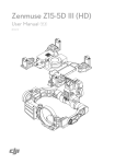
RRG SERIES HEAVY DUTY GAS
GRIDDLE
24RRG
36RRG
48RRG
60RRG
ML-135339-00024
ML-135340-00036
ML-135341-00048
ML-135342-00060
24RRG Shown
- NOTICE This Manual is prepared for the use of trained Vulcan Service
Technicians and should not be used by those not properly
qualified.
This manual is not intended to be all encompassing. If you have
not attended a Vulcan Service School for this product, you should
read, in its entirety, the repair procedure you wish to perform to
determine if you have the necessary tools, instruments and skills
required to perform the procedure. Procedures for which you do
not have the necessary tools, instruments and skills should be
performed by a trained Vulcan Service Technician.
The reproduction, transfer, sale or other use of this Manual,
without the express written consent of Vulcan, is prohibited.
This manual has been provided to you by ITW Food Equipment
Group LLC ("ITW FEG") without charge and remains the property
of ITW FEG, and by accepting this manual you agree that you will
return it to ITW FEG promptly upon its request for such return at
any time in the future.
A product of Vulcan-Hart
3600 North Point Blvd Baltimore, MD 21222
F45514 (0214)
RRG SERIES HEAVY DUTY GAS GRIDDLE
TABLE OF CONTENTS
GENERAL . . . . . . . . . . . . . . . . . . . . . . . . . . . . . . . . . . . . . . . . . . . . . . . . . . . . . . . . . . . . . . . . . . . . . . . . . . . . . . . . . . . . . . . . . . . . . . . . . .
INTRODUCTION . . . . . . . . . . . . . . . . . . . . . . . . . . . . . . . . . . . . . . . . . . . . . . . . . . . . . . . . . . . . . . . . . . . . . . . . . . . . . . . . . . . . . . .
INSTALLATION . . . . . . . . . . . . . . . . . . . . . . . . . . . . . . . . . . . . . . . . . . . . . . . . . . . . . . . . . . . . . . . . . . . . . . . . . . . . . . . . . . . . . . . .
OPERATION . . . . . . . . . . . . . . . . . . . . . . . . . . . . . . . . . . . . . . . . . . . . . . . . . . . . . . . . . . . . . . . . . . . . . . . . . . . . . . . . . . . . . . . . . . .
SPECIFICATIONS . . . . . . . . . . . . . . . . . . . . . . . . . . . . . . . . . . . . . . . . . . . . . . . . . . . . . . . . . . . . . . . . . . . . . . . . . . . . . . . . . . . . . .
TOOLS . . . . . . . . . . . . . . . . . . . . . . . . . . . . . . . . . . . . . . . . . . . . . . . . . . . . . . . . . . . . . . . . . . . . . . . . . . . . . . . . . . . . . . . . . . . . . . . . .
3
3
3
3
3
3
REMOVAL AND REPLACEMENT OF PARTS . . . . . . . . . . . . . . . . . . . . . . . . . . . . . . . . . . . . . . . . . . . . . . . . . . . . . . . . . . . . . . . 5
CONTROL PANEL . . . . . . . . . . . . . . . . . . . . . . . . . . . . . . . . . . . . . . . . . . . . . . . . . . . . . . . . . . . . . . . . . . . . . . . . . . . . . . . . . . . . . 5
BACK PANEL . . . . . . . . . . . . . . . . . . . . . . . . . . . . . . . . . . . . . . . . . . . . . . . . . . . . . . . . . . . . . . . . . . . . . . . . . . . . . . . . . . . . . . . . . . 5
BULL NOSE . . . . . . . . . . . . . . . . . . . . . . . . . . . . . . . . . . . . . . . . . . . . . . . . . . . . . . . . . . . . . . . . . . . . . . . . . . . . . . . . . . . . . . . . . . . . 5
THERMOCOUPLE . . . . . . . . . . . . . . . . . . . . . . . . . . . . . . . . . . . . . . . . . . . . . . . . . . . . . . . . . . . . . . . . . . . . . . . . . . . . . . . . . . . . . 6
REMOVAL . . . . . . . . . . . . . . . . . . . . . . . . . . . . . . . . . . . . . . . . . . . . . . . . . . . . . . . . . . . . . . . . . . . . . . . . . . . . . . . . . . . . . . . . . 6
INSTALLATION . . . . . . . . . . . . . . . . . . . . . . . . . . . . . . . . . . . . . . . . . . . . . . . . . . . . . . . . . . . . . . . . . . . . . . . . . . . . . . . . . . . . 6
TEMPERATURE CONTROLLER . . . . . . . . . . . . . . . . . . . . . . . . . . . . . . . . . . . . . . . . . . . . . . . . . . . . . . . . . . . . . . . . . . . . . . . . 6
BURNER . . . . . . . . . . . . . . . . . . . . . . . . . . . . . . . . . . . . . . . . . . . . . . . . . . . . . . . . . . . . . . . . . . . . . . . . . . . . . . . . . . . . . . . . . . . . . . . 7
PILOT BURNER . . . . . . . . . . . . . . . . . . . . . . . . . . . . . . . . . . . . . . . . . . . . . . . . . . . . . . . . . . . . . . . . . . . . . . . . . . . . . . . . . . . . . . . . 7
IGNITION MODULE . . . . . . . . . . . . . . . . . . . . . . . . . . . . . . . . . . . . . . . . . . . . . . . . . . . . . . . . . . . . . . . . . . . . . . . . . . . . . . . . . . . . 8
DUAL SOLENOID VALVES . . . . . . . . . . . . . . . . . . . . . . . . . . . . . . . . . . . . . . . . . . . . . . . . . . . . . . . . . . . . . . . . . . . . . . . . . . . . . 9
SINGLE SOLENOID VALVE . . . . . . . . . . . . . . . . . . . . . . . . . . . . . . . . . . . . . . . . . . . . . . . . . . . . . . . . . . . . . . . . . . . . . . . . . . . 10
GAS PRESSURE REGULATOR . . . . . . . . . . . . . . . . . . . . . . . . . . . . . . . . . . . . . . . . . . . . . . . . . . . . . . . . . . . . . . . . . . . . . . . 11
REMOVAL . . . . . . . . . . . . . . . . . . . . . . . . . . . . . . . . . . . . . . . . . . . . . . . . . . . . . . . . . . . . . . . . . . . . . . . . . . . . . . . . . . . . . . . . 11
INSTALLATION . . . . . . . . . . . . . . . . . . . . . . . . . . . . . . . . . . . . . . . . . . . . . . . . . . . . . . . . . . . . . . . . . . . . . . . . . . . . . . . . . . . 11
GRIDDLE PLATE ASSEMBLY . . . . . . . . . . . . . . . . . . . . . . . . . . . . . . . . . . . . . . . . . . . . . . . . . . . . . . . . . . . . . . . . . . . . . . . . . 11
SERVICE PROCEDURES AND ADJUSTMENTS . . . . . . . . . . . . . . . . . . . . . . . . . . . . . . . . . . . . . . . . . . . . . . . . . . . . . . . . . . .
TEMPERATURE CONTROL CALIBRATION . . . . . . . . . . . . . . . . . . . . . . . . . . . . . . . . . . . . . . . . . . . . . . . . . . . . . . . . . . .
BURNER AIR SHUTTER ADJUSTMENT . . . . . . . . . . . . . . . . . . . . . . . . . . . . . . . . . . . . . . . . . . . . . . . . . . . . . . . . . . . . . . .
REGULATOR ADJUSTMENT . . . . . . . . . . . . . . . . . . . . . . . . . . . . . . . . . . . . . . . . . . . . . . . . . . . . . . . . . . . . . . . . . . . . . . . . . .
BURNER NOZZLE CHECK . . . . . . . . . . . . . . . . . . . . . . . . . . . . . . . . . . . . . . . . . . . . . . . . . . . . . . . . . . . . . . . . . . . . . . . . . . . .
THERMOCOUPLE TEST . . . . . . . . . . . . . . . . . . . . . . . . . . . . . . . . . . . . . . . . . . . . . . . . . . . . . . . . . . . . . . . . . . . . . . . . . . . . . .
TEMPERATURE CONTROLLER TEST . . . . . . . . . . . . . . . . . . . . . . . . . . . . . . . . . . . . . . . . . . . . . . . . . . . . . . . . . . . . . . . .
IGNITION MODULE TEST . . . . . . . . . . . . . . . . . . . . . . . . . . . . . . . . . . . . . . . . . . . . . . . . . . . . . . . . . . . . . . . . . . . . . . . . . . . . .
PILOT BURNER FLAME ADJUSTMENT . . . . . . . . . . . . . . . . . . . . . . . . . . . . . . . . . . . . . . . . . . . . . . . . . . . . . . . . . . . . . . .
SOLENOID VALVE TESTS . . . . . . . . . . . . . . . . . . . . . . . . . . . . . . . . . . . . . . . . . . . . . . . . . . . . . . . . . . . . . . . . . . . . . . . . . . . .
12
12
13
13
14
15
15
16
16
17
ELECTRICAL OPERATION . . . . . . . . . . . . . . . . . . . . . . . . . . . . . . . . . . . . . . . . . . . . . . . . . . . . . . . . . . . . . . . . . . . . . . . . . . . . . . . .
COMPONENT FUNCTION . . . . . . . . . . . . . . . . . . . . . . . . . . . . . . . . . . . . . . . . . . . . . . . . . . . . . . . . . . . . . . . . . . . . . . . . . . . .
SEQUENCE OF OPERATION . . . . . . . . . . . . . . . . . . . . . . . . . . . . . . . . . . . . . . . . . . . . . . . . . . . . . . . . . . . . . . . . . . . . . . . . .
24" GRIDDLE - WIRING DIAGRAM . . . . . . . . . . . . . . . . . . . . . . . . . . . . . . . . . . . . . . . . . . . . . . . . . . . . . . . . . . . . . . . . . . . .
36" GRIDDLE - WIRING DIAGRAM . . . . . . . . . . . . . . . . . . . . . . . . . . . . . . . . . . . . . . . . . . . . . . . . . . . . . . . . . . . . . . . . . . . .
48" GRIDDLE - WIRING DIAGRAM . . . . . . . . . . . . . . . . . . . . . . . . . . . . . . . . . . . . . . . . . . . . . . . . . . . . . . . . . . . . . . . . . . . .
60" GRIDDLE - WIRING DIAGRAM . . . . . . . . . . . . . . . . . . . . . . . . . . . . . . . . . . . . . . . . . . . . . . . . . . . . . . . . . . . . . . . . . . . .
18
18
18
20
21
22
23
TROUBLESHOOTING . . . . . . . . . . . . . . . . . . . . . . . . . . . . . . . . . . . . . . . . . . . . . . . . . . . . . . . . . . . . . . . . . . . . . . . . . . . . . . . . . . . . . 24
TROUBLESHOOTING . . . . . . . . . . . . . . . . . . . . . . . . . . . . . . . . . . . . . . . . . . . . . . . . . . . . . . . . . . . . . . . . . . . . . . . . . . . . . . . . . 24
© VULCAN 2014
F45514 (0214)
Page 2 of 24
RRG SERIES HEAVY DUTY GAS GRIDDLE - GENERAL
GENERAL
INTRODUCTION
SPECIFICATIONS
This Service Manual covers specific service
information related to the models listed on the front
cover. Procedures in this manual will apply to all RRG
Heavy Duty Gas Griddles unless otherwise specified.
Raising of the griddle plate is not required for servicing
the griddle components. Griddle components are
serviced through the front and rear. Pictures and
illustrations can be of any model unless the picture or
illustration needs to be model specific.
The RRG, Rapid Recovery Griddle, plate is a
composite material which is engineered to provide a
high heat transfer rate to the food. The top surface can
be scored or dented by careless use of a spatula or
scraper. The center of the of the plate is an aluminum
core with sheets of stainless steel laminated to the top
and bottom exterior surfaces.
INSTALLATION
Electrical
- 120VAC 50/60Hz 1 Amp single phase.
- 6 foot corded plug with ground supplied.
Gas Manifold Pressure:
- Natural Gas 5.0" W.C.
- Propane Gas 10.0" W.C.
- Gas pressure regulator supplied with the unit must
be installed.
Incoming Gas Pressure:
- 7" to 9" W.C. Natural Gas
- 11" to 12" W.C. Propane Gas.
- Incoming pressure should not exceed 14.0" W.C.
(0.5 PSI) for either gas type.
Burners
Generally, installations are made by the dealer or
contracted by the dealer or owner. Detailed
installation instructions are included in F-36981
Installation & Operation Manual that is sent with each
unit.
It should be noted that an improperly installed unit,
especially an unlevel unit can lead to premature
electrical component failures. A unit that is higher in
the front will cause the flue gases to vent improperly
and gather in the front near the electrical components.
All RRG models must be installed with an externally
mounted regulator.
The models, number of burners and BTU/HR input
rating are listed under GENERAL in the Installation &
Operation Manual.
- One 27,500 BTU/HR “U” shaped aluminized steel
burner for each 12" of griddle width.
Controls
- One Solid State thermostat with embeded
thermocouple for each 12" of griddle width.
- Temperature adjustment range 150°F to 450°F.
- Electronic ignition module with pilot safety system.
- There is one pilot for every two burners. A flash tube
mounted between two burners is used to light the
ignition ports on the burners.
- On 36” and 60” griddles there is an odd number of
burners to light. One pilot and one electronic ignition
module on these griddles will control a single burner
only.
OPERATION
TOOLS
Detailed operation instructions are included in the
Installation & Operation Manual sent with each unit.
The manual is also available online at
www.vulcanequipment.com.
The operation of the griddle controls, pilots and
burners are outlined under CONTROLS in the
Installation & Operation Manual.
Standard
•
Standard set of hand tools.
•
VOM and meter leads rated CAT III 600v or
higher. Meter must also have a certification.
•
Temperature tester (K type thermocouple
preferred) with surface probe.
•
U-Tube or Digital Manometer.
Page 3 of 24
F45514 (0214)
RRG SERIES HEAVY DUTY GAS GRIDDLE - GENERAL
•
Thread sealant suitable for use with natural or
propane gas.
Special
•
Torque wrench capable of measuring at least 25
in-lbs. for tightening thermocouple probe to
griddle plate. Bolt size 5/16"-18.
•
Safekote 60 or equivalent Heat Transfer and
Anti-Seize Compound rated for 600°F (purchase
locally). Apply to thermocouple probe.
•
Clear silicone sealant
F45514 (0214)
Page 4 of 24
RRG SERIES HEAVY DUTY GAS GRIDDLE - REMOVAL AND REPLACEMENT OF PARTS
REMOVAL AND REPLACEMENT OF PARTS
3.
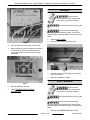
CONTROL PANEL
Remove all screws from rear of griddle securing
the back panel.
Disconnect the
electrical power to the machine and
follow lockout / tagout procedures.
The Control Panel holds the thermostats, indicator
lights and power switch.
1.
Remove four screws securing the front of control
panel to frame.
Fig. 2
4.
Reverse procedure to install.
BULL NOSE
Disconnect the
electrical power to the machine and
follow lockout / tagout procedures.
Fig. 1
2.
Remove screw(s) that secure the bottom lip of
the control panel to the frame. The total number
of screws depend on the width of the griddle.
3.
Pull control panel forward and lay face down in
front of the unit while servicing.
4.
Reverse procedure to install.
1.
Remove CONTROL PANEL.
2.
Remove all screws securing bull nose to griddle.
The total number of screws depend on the width
of the griddle.
BACK PANEL
Disconnect the
electrical power to the machine and
follow lockout / tagout procedures.
Fig. 3
Shut off the gas before servicing the
3.
Lift bull nose off griddle.
4.
Reverse procedure to install.
unit.
NOTE: Remove the back panel when changing a
burner, temperature probe or to remove excessive
grease build up from the flue area.
1.
Disconnect gas supply at griddle.
2.
Remove GAS PRESSURE REGULATOR.
Page 5 of 24
F45514 (0214)
RRG SERIES HEAVY DUTY GAS GRIDDLE - REMOVAL AND REPLACEMENT OF PARTS
THERMOCOUPLE
Disconnect the
electrical power to the machine and
follow lockout / tagout procedures.
Shut off the gas before servicing the
unit.
All gas joints disturbed during
servicing must be checked for leaks. Check with a
soap and water solution (bubbles). Do not use an open
flame.
Fig. 5
Removal
Installation
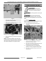
1.
Remove CONTROL PANEL.
1.
2.
Note thermocouple connections then disconnect
from temperature controller.
Apply a thin coating of heat transfer and antiseize compound to the probe tip and mounting
nut threads.
2.
From rear of griddle, route thermocouple wires
and probe through the opening in heat shield.
3.
Thread temperature probe into the mounting hole
in griddle plate and stop when probe tip touches
the plate. Torque the mounting nut to a maximum
of 25 in-lbs.
Do not over tighten or damage to the
thermocouple probe may occur. Due to the aluminum
plate core, It is also possible to create a raised area
over the probe if overtightened.
4.
TEMPERATURE CONTROLLER
Fig. 4
3.
Remove BACK PANEL.
4.
From rear of griddle, loosen mounting nut and
remove probe from bottom of griddle plate.
F45514 (0214)
Check TEMPERATURE CONTROL
CALIBRATION.
Disconnect the
electrical power to the machine and
follow lockout / tagout procedures.
1.
Remove CONTROL PANEL.
2.
Note wire connections then disconnect them
from temperature controller.
Page 6 of 24
RRG SERIES HEAVY DUTY GAS GRIDDLE - REMOVAL AND REPLACEMENT OF PARTS
BURNER
Disconnect the
electrical power to the machine and
follow lockout / tagout procedures.
Shut off the gas before servicing the
unit.
All gas joints disturbed during
servicing must be checked for leaks. Check with a
soap and water solution (bubbles). Do not use an open
flame.
Fig. 6
3.
Remove knob from temperature control shaft.
4.
Note temperature control orientation as mounted
to control panel. Remove mounting nut from
temperature control shaft and remove control
from panel.
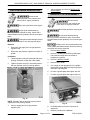
1.
Remove BACK PANEL.
2.
Remove the nut that is securing burner.
Fig. 8
3.
Lift back of burner until locating pin clears hole
and pull out burner.
4.
Reverse proceedure to install.
PILOT BURNER
Fig. 7
5.
Reverse procedure to install.
6.
Check TEMPERATURE CONTROL
CALIBRATION.
Disconnect the
electrical power to the machine and
follow lockout / tagout procedures.
Shut off the gas before servicing the
unit.
All gas joints disturbed during
servicing must be checked for leaks. Check with a
soap and water solution (bubbles). Do not use an open
flame.
1.
Page 7 of 24
Remove GAS PRESSURE REGULATOR.
F45514 (0214)
RRG SERIES HEAVY DUTY GAS GRIDDLE - REMOVAL AND REPLACEMENT OF PARTS
2.
Access ignition module, and disconnect high
voltage spark wire.
Fig. 9
3.
Remove CONTROL PANEL.
4.
Lift griddle at the front and support it from
underneath for access to the pilot. (Be aware of
the main gas line at the rear when tilting)
5.
Fig. 11
7.
Disconnect flex tubing from pilot burner
assembly.
8.
Pull high voltage spark wire through bottom of
griddle.
9.
Reverse procedure to install.
Remove pilot bracket retaining screw.
NOTE: When installing, verify spark gap is 1/8".
10. Check for proper operation.
IGNITION MODULE
Disconnect the
electrical power to the machine and
follow lockout / tagout procedures.
Fig. 10
6.
Position pilot assembly to give you the easiest
access to the compression fitting on the pilot
assembly.
F45514 (0214)
1.
Remove grease tray
2.
Remove two screws holding ignition module
cover in place and pull it down.
Page 8 of 24
RRG SERIES HEAVY DUTY GAS GRIDDLE - REMOVAL AND REPLACEMENT OF PARTS
DUAL SOLENOID VALVES
Disconnect the
electrical power to the machine and
follow lockout / tagout procedures.
Shut off the gas before servicing the
unit.
All gas joints disturbed during
servicing must be checked for leaks. Check with a
soap and water solution (bubbles). Do not use an open
flame.
Fig. 12
3.
Disconnect high voltage spark wire and control
wire harness female connector.
4.
Remove two mountingnuts and screws holding
the ignigtion module to the cover.
1.
Remove CONTROL PANEL.
NOTE: Plumbing and type of burner solenoid valves
may vary slightly between different units.
2.
Label and disconnect dual solenoid valve
connectors.
Fig. 13
5.
Reverse proceedure for install and verify proper
operation.
NOTE: Clear silicone sealant on the control wire
harness female connector will need to be cleaned off.
Apply clear silicone sealant around the connector to
seal it before installation of new ignition module.
Fig. 14
3.
Remove retaining screw that is holding dual
solenoid valve body in bracket.
4.
Disconnect compression fittings and remove flex
tubing from front of dual solenoid valve.
5.
Lift dual solenoid valve out of bracket and
arrange it to access compression fitting in back.
6.
Disconnect compression fitting in back of dual
solenoid valve.
Page 9 of 24
F45514 (0214)
RRG SERIES HEAVY DUTY GAS GRIDDLE - REMOVAL AND REPLACEMENT OF PARTS
4.
Disconnect compression fitting and remove flex
tubing from front of single solenoid valve.
Fig. 15
7.
Remove the three NPT elbows. Two on front and
one on the back of dual solenoid valve.
NOTE: Be sure to note positioning of NPT elbows on
dual solenoid valve.
8.
5.
Lift solenoid out of bracket and arrange it to
access compression fitting in back of single
solenoid valve.
6.
Disconnect compression fitting in back of single
solenoid valve.
7.
Remove street elbow and NPT elbow from single
solenoid valve.
Reverse proceedure for installation.
NOTE: When installing solenoid valves be sure that
the coil valve clamp is placed correctly and that the
valve clamp hold down nut is securely tightened.
Clean pipe threads and apply thread
sealant that is suitable for use with propane gases.
9.
Fig. 16
Check for proper operation.
SINGLE SOLENOID VALVE
Disconnect the
electrical power to the machine and
follow lockout / tagout procedures.
Shut off the gas before servicing the
unit.
All gas joints disturbed during
servicing must be checked for leaks. Check with a
soap and water solution (bubbles). Do not use an open
flame.
1.
Remove CONTROL PANEL.
NOTE: Be sure to note the positioning of the elbow.
8.
NOTE: Plumbing and type of Single Solenoid Valve
may vary slightly between different units.
2.
Label and disconnect connectors on single
solenoid valve.
3.
Remove retaining screws that are holding single
solenoid valve body in bracket.
F45514 (0214)
Fig. 17
Reverse proceedure for installation.
Clean pipe threads and apply thread
sealant that is suitable for use with propane gases.
9.
Page 10 of 24
Check for proper operation.
RRG SERIES HEAVY DUTY GAS GRIDDLE - REMOVAL AND REPLACEMENT OF PARTS
4.
GAS PRESSURE REGULATOR
Adjust regulator as outlined in REGULATOR
ADJUSTMENT.
GRIDDLE PLATE ASSEMBLY
Disconnect the
electrical power to the machine and
follow lockout / tagout procedures.
Disconnect the
electrical power to the machine and
follow lockout / tagout procedures.
Shut off the gas before servicing the
unit.
All gas joints disturbed during
servicing must be checked for leaks. Check with a
soap and water solution (bubbles). Do not use an open
flame.
Clean pipe threads and apply thread
sealant that is suitable for use with propane gases.
Removal
1.
Disconnect gas supply line from gas pressure
regulator inlet.
2.
Disconnect gas pressure regulator from back of
griddle.
Shut off the gas before servicing the
unit.
All gas joints disturbed during
servicing must be checked for leaks. Check with a
soap and water solution (bubbles). Do not use an open
flame.
For larger units, removal and replacement
of the griddle plate weld assembly should be done by
more than one service technician .
1.
Remove BACK PANEL.
2.
Remove THERMOCOUPLEfrom griddle plate.
Leave thermocouple wires connected at
temperature controller.
3.
Remove CONTROL PANEL.
4.
Remove BULL NOSE.
5.
Cut a length of 2x4 appropriate for the griddle
plate width, leaving additional length to grasp on
each side of griddle plate.
6.
Lift front of griddle plate and support with 2x4.
7.
Lift back of griddle plate and support with 2x4.
Installation
1.
Thread regulator onto pipe hand tight with arrow
pointing in direction of gas flow to the griddle.
2.
Tighten regulator securely in horizontal position
with the regulator closing nut facing upward.
Fig. 18
NOTE: Regulator will not function properly without
adjustment screw pointing upward.
3.
Connect supply gas line to gas pressure
regulator inlet.
Fig. 19
8.
Lift Griddle plate and remove from base of
equipment.
9.
Reverse procedure for installation.
Page 11 of 24
F45514 (0214)
RRG SERIES HEAVY DUTY GAS GRIDDLE - SERVICE PROCEDURES AND ADJUSTMENTS
SERVICE PROCEDURES AND ADJUSTMENTS
•
TEMPERATURE CONTROL
CALIBRATION
NOTE: Ensure the griddle is level before performing
calibration as outlined under LEVELING in the
Installation & Operation Manual.
NOTE: Do not use an infrared thermometer for
measuring griddle surface temperatures. These
devices are highly sensitive to surface color (clean or
dirty), angle of reading and distance from the surface.
Use a temperature meter with surface probe for all
griddle surface temperature measurments.
Fig. 20
1.
Each temperature controller controls a 12" zone
of the griddle. Center point area of cooking zones
are located 6" from the side splash (left or right),
every 12" across the width of griddle, and 12"
back from the front of griddle plate.
2.
Clean the center point areas of cooking zones to
ensure good contact with surface probe.
3.
Set thermostats to 350°F and allow the indicator
light to cycle ON and OFF at least three times to
stabilize griddle surface temperatures.
4.
Monitor indicator light for the temperature
controller calibration being checked. When the
light cycles OFF, measure temperature for that
zone and record.
•
If tempereature measurement is 350°F ±5°F the
control is propererly calibrated.
F45514 (0214)
If temperature measurement is outside of
tolerance then temperature control must be
calibrated.
CALIBRATING TEMPERATURE CONTROL
Never adjust the screw on the back side
of the temperature controller. This will ruin the factory
calibration; the temperature controller will no longer
operate properly and will need to be replaced.
1.
Use the temperature scale on the overlay as a
guide. Align the edge on a short piece of tape to
the temperature recorded in STEP 4 and apply
tape to knob as a reference point.
2.
Remove knob from temperature control shaft. Do
not rotate the knob during removal.
3.
Loosen screws on the back of dial. With knob
facing user, a clockwise rotation increases
temperature and a counterclockwise rotation
decrease temperature.
4.
Hold the knob and rotate dial to the edge of the
tape used for reference. This adjustment offsets
the indicated temperature on the dial to the actual
temperature measured.
5.
Hold the dial and knob together to maintain the
setting and tighten screws.
6.
Install the knob back onto the temperature
control shaft.
7.
Repeat "TEMPERATURE CHECK." Adjust
calibration until temperature is within tolerance.
Page 12 of 24
RRG SERIES HEAVY DUTY GAS GRIDDLE - SERVICE PROCEDURES AND ADJUSTMENTS
BURNER AIR SHUTTER
ADJUSTMENT
Disconnect the
electrical power to the machine and
follow lockout / tagout procedures.
3.
Install burner.
4.
Install GAS PRESSURE REGULATOR.
5.
Connect power to machine.
6.
Turn on power and rotate temperature controller
to call for heat.
7.
Observe flame from back of machine.
A.
If a proper flame is observed as described
in the beginning paragraph, no further
adjustment is necessary.
B.
If flame is yellow tipping and lifting from
burner, continue with procedure to adjust.
Shut off the gas before servicing the
unit.
Clean pipe threads and apply thread
sealant that is suitable for use with propane gases.
8.
Disconnect power.
All gas joints disturbed during
servicing must be checked for leaks. Check with a
soap and water solution (bubbles). Do not use an open
flame.
9.
Remove burner, being sure to keep shutter in the
current position.
The efficiency of the burner depends on a delicate
balance between the air supply and volume of gas.
Whenever this balance is disturbed, poor operating
characteristics and excessive gas consumption may
occur. An air shutter on the front of the burner controls
the gas mixer balance. A yellow streaming flame on
the burner is an indication of insufficient primary air. A
proper flame should be blue in color, well-defined and
seated on the burner port. A white-blue flame is a
result of excessive primary air.
11. Install BURNER.
1.
Remove BURNER.
2.
Loosen the shutter screw and rotate the air
shutter.
10. Open the shutter slightly and tighten the shutter
screw.
12. Test machine to verify proper operation.
NOTE: The factory default air shutter positions are
half open natural; full open propane.
REGULATOR ADJUSTMENT
Shut off the gas before servicing the
unit.
All gas joints disturbed during
servicing must be checked for leaks. Check with a
soap and water solution (bubbles). Do not use an open
flame.
NOTE: Regulators come preset, but should be
checked anytime one is installed. Before adjusting
regulator, check incoming gas line pressure. Incoming
pressure must be 7-14" W.C. for natural gas and
12-14" W.C. for propane gas. If incoming pressure is
not correct, have the gas source checked and
adjusted as necessary. Make sure the regulator is
mounted in the horizontal position with the arrow
pointing in the direction of gas flow. See unit data
plate, riveted on right side panel towards front of unit,
for manifold pressure setting information. Clean vent
cap before adjusting.
Fig. 21
Page 13 of 24
F45514 (0214)
RRG SERIES HEAVY DUTY GAS GRIDDLE - SERVICE PROCEDURES AND ADJUSTMENTS
Fig. 24
4.
Insert a flat edge screwdriver through the top of
the regulator. While watching the manometer,
turn the adjusting screw clockwise to increase
pressure and counterclockwise to decrease
pressure.
5.
Install the regulator closing nut.
Fig. 22
1.
Remove pressure tap plug and connect
manometer to the pressure tap located on the far
left burner port.
Clean pipe threads and apply thread
sealant that is suitable for use with propane gases.
6.
Reninstall pressure tap plug.
BURNER NOZZLE CHECK
Disconnect the
electrical power to the machine and
follow lockout / tagout procedures.
Shut off the gas before servicing the
unit.
Fig. 23
2.
Check manometer reading. The reading should
be 5" W.C. for natural gas and 10" W.C. for
propane gas. Tolerance is ±0.3" W.C.
3.
If manifold pressure is not correct, adjust the
regulator. Remove the regulator closing nut.
F45514 (0214)
The burner nozzle is mounted between the griddle gas
supply tubing/mounting bracket and the u-burner
assembly. If burner operation seems poor and other
systems have been checked, access the burner for
the griddle section being serviced and remove the
burner nozzle.
1.
Page 14 of 24
Check for blockage or damage.
RRG SERIES HEAVY DUTY GAS GRIDDLE - SERVICE PROCEDURES AND ADJUSTMENTS
TEMPERATURE CONTROLLER
TEST
Disconnect the
electrical power to the machine and
follow lockout / tagout procedures.
Fig. 25
2.
1.
Access the TEMPERATURE CONTROLLER.
2.
Connect power to the machine.
3.
Turn on the power switch.
4.
Verify temperature controller is receiving
120VAC at terminals L1 & L2, polarity is correct
and machine is properly grounded.
Verify gas orifice hood is correct for the altitude.
See Parts Catalog for Orifice Hood Chart.
THERMOCOUPLE TEST
Disconnect the
electrical power to the machine and
follow lockout / tagout procedures.
1.
Access TEMPERATURE CONTROLLER.
2.
Remove thermocouple connections from
temperature controller.
Fig. 27
5.
Set temperature dial to 350°F.
6.
Verify indicator light comes on and burner lights.
A.
NOTE: Temperature controller will de-energize
internal relay if the circuitry detects an open
thermocouple.
Fig. 26
3.
Check the thermocouple for resistance.
A.
4.
If heat light and main burners come on but
turn off within 10 seconds, Perform
THERMOCOUPLE TEST .
If meter reads an overload (OL) condition
(open), or zero ohms (short) replace the
thermocouple and check temperature
controller for proper operation.
B.
If heat light and main burners do not come
on, verify internal relay contacts are
operating properly. Check for 120VAC dual
solenoid valve.
If resistance is measured, thermocouple is good.
Page 15 of 24
F45514 (0214)
RRG SERIES HEAVY DUTY GAS GRIDDLE - SERVICE PROCEDURES AND ADJUSTMENTS
IGNITION MODULE TEST
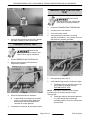
PILOT BURNER FLAME
ADJUSTMENT
NOTE: Sparking will continue until pilot flame is
established, at which point sparking will terminate. If
no pilot flame is established the sparking will continue
until power is removed from unit.
1.
Turn on power switch.
2.
Single solenoid valve energizes allowing gas to
flow to pilot burner.
3.
Ignition module is energized and ignition starts.
4.
If there is no spark then check the following.
Disconnect the
electrical power to the machine and
follow lockout / tagout procedures.
A.
Check for 120VAC at ignition module.
The RRG series griddle utilizes a solenoid valve and
straight compression fitting with needle valve
adjustment to control gas flow to pilot burners. One to
three pilot burners can be fed by one valve. One leg
of which may be branched.
B.
Verify spark gap is set at 1/8".
1.
Remove CONTROL PANEL.
C.
Inspect eletrode wire for damage and
continuity.
2.
Remove dual solenoid valve connectors.
D.
If component passes all above tests and is
not sparking, then replace ignition module.
Fig. 29
Fig. 28
5.
6.
Pilot burner lights and flame is sensed. If
electrode continues to spark after pilot is lit then
check the following.
NOTE: Removing the dual solenoid valve connectors
will prevent the main burners from lighting.
3.
Connect power to machine.
A.
Verify the electrode is fully engulfed by pilot
flame.
4.
Turn on power switch, and adjust temperature
control to call for heat.
B.
Verify that ground wire from pin 1 is securely
grounded to chassis.
As long as the ignition control module is sensing
flame current, then the pilot will stay lit.
5.
F45514 (0214)
Page 16 of 24
A.
If flame envelops 3/8" to 1/2" of the ignitor/
flame sense electrode, pilot burner is
adjusted properly.
B.
If flame is outside of specified range,
continue with procedure.
Locate the proper needle valve and adjust.
RRG SERIES HEAVY DUTY GAS GRIDDLE - SERVICE PROCEDURES AND ADJUSTMENTS
Fig. 30
A.
To increase pilot flame turn valve needle
counterclockwise. To decrease pilot flame,
turn valve needle clockwise.
6.
Once pilot flame is adjusted correctly, turn off
power switch.
7.
Connect dual solenoid valve connectors.
8.
Install CONTROL PANEL.
9.
Check for proper operation.
Fig. 31
SOLENOID VALVE TESTS
Disconnect the
electrical power to the machine and
follow lockout / tagout procedures.
1.
Remove CONTROL PANEL.
2.
Check for proper gas pressure.
3.
Connect power to machine.
4.
Turn on power switch and adjust temperature
controls to call for heat.
5.
Check for 120VAC between both terminals on
each solenoid.
Fig. 32
A.
On single solenoid valve, if no voltage check wiring and on/off power switch.
B.
On dual solenoid valve if no voltage - check
wiring, IGNITION MODULE, and
TEMPERATURE CONTROLLER.
6.
If 120VAC is present between two terminals after
performing previous steps, either the solenoid
coil or valve is malfunctioning.
7.
To determine if solenoid coil is malfunctioning,
check resistance between both terminals on
solenoid. Readings of 100 ohms or less indicate
a shorted coil. Solenoid needs replaced.
Page 17 of 24
F45514 (0214)
RRG SERIES HEAVY DUTY GAS GRIDDLE - ELECTRICAL OPERATION
ELECTRICAL OPERATION
COMPONENT FUNCTION
Temperature Control . . . Controls griddle surface temperature for the individual heat zone by monitoring
thermocouple input (K type ).
Temperature Probe . . .
Senses griddle surface temperature for the heat zone using a K type thermocouple.
Provides input to the temperature control.
Power Switch . . . . . . . .
Controls power to all electrical components (single solenoid valve, temperature control
and ignition module) (SPST switch).
Indicator Light . . . . . . .
When brightly lit, the light indicates temperature control is calling for heat (internal
contacts closed) and ignition module output from pin 2 is on. Dual solenoid valve is
energized (burner on).
The light will be dimly lit after the pilot burner is on.
The light is off during trial for ignition (pilot lighting) or when the pilot safety circuit is not
satisfied (pilot not lit).
Ignition Module . . . . . .
Controls and monitors gas heating. Generates spark to light gas at the pilot burner,
monitors the presence of flame and energizes the dual solenoid valve upon a call for heat
from the temperature control (continuous try module).
Ignitor/Flame Sense
Electrode . . . . . . . . . . . . .
Ignites pilot burner and senses the presence of a flame. The Ignitor/Flame Sense is a
component of the pilot burner.
Single Solenoid Valve . . . Controls gas to pilot burner. Single solenoid valve is energized when power switch is on.
Depending on the width of the griddle, there may not be a single solenoid valve. The
solenoid valve used to control gas flow to the pilot burner may be one of the dual solenoid
valves. Valves that control gas flow to the pilot burner have an adjustment screw for pilot
flame height at the output on the valve body.
Dual Solenoid Valve(s) . . .Controls gas to burner. Dual solenoid valve is energized by the ignition module after pilot
safety circuit is established (pilot lit) and temperature control is calling for heat. Depending
on the width of the griddle, the dual solenoid valve can be used to control gas flow one
of the main burners along with the pilot pilot burner.
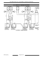
SEQUENCE OF OPERATION
Operation is the same for all griddle models. Each 12"
heat zone on the griddle plate has its own temperature
controller, indicator light and ignition system
components. Refer to the wiring diagram for the model
being serviced.
•
24" GRIDDLE - WIRING DIAGRAM
•
36" GRIDDLE - WIRING DIAGRAM
•
48" GRIDDLE - WIRING DIAGRAM
•
60" GRIDDLE - WIRING DIAGRAM
1.
Conditions.
A.
120VAC connected to griddle and is
properly grounded.
F45514 (0214)
2.
B.
Incoming neutral line (L2) is connected to
power switch terminal 3 (non switching) and
jumpered to one side of single solenoid
valve; and each temperature controller at
terminals - L2 and com; and each ignition
module at pin 3.
C.
Incoming hot line (L1) is connected to power
switch terminal 2.
D.
Power switch OFF (SPST).
E.
Temperature dials at lowest setting.
F.
Griddle temperature below 150°F.
G.
Gas supply on.
Turn power switch ON - 120VAC applied to the
following components:
NOTE: Temperature control terminal L1 (hot) and
ignition module pin 4 (hot) are "jumpered" between
Page 18 of 24
RRG SERIES HEAVY DUTY GAS GRIDDLE - ELECTRICAL OPERATION
each of the installed temperature controllers and
ignition modules on the griddle.
3.
C.
4.
A.
Single solenoid valve energized and gas
flows to pilot burner.
B.
Temperature controllers are powered.
C.
Ignition modules are powered.
Ignition modules generate a spark voltage from
the high voltage terminal to begin sparking at the
ignitor/flame sense electrodes.
A.
Pilot burner lights, flame is sensed and
ignitors stops sparking.
5.
B.
Ignition modules output L1 (hot) from pin 2
on the connector to one side of dual
solenoid valve and indicator lights.
Page 19 of 24
Indicator lights are dimly lit.
Turn temperature dials to 350°F.
A.
Temperature controller N.O. contacts close
and provide L2 (neutral) to the other side of
dual solenoid valve.
B.
Dual solenoid valve energized and gas
flows to burners. Burners light and begin
heating griddle.
C.
Indicator lights are brightly lit.
Griddle will continue to cycle with the
temperature controllers until the temperature dial
is turned down or the power switch is turned off.
F45514 (0214)
RRG SERIES HEAVY DUTY GAS GRIDDLE - ELECTRICAL OPERATION
24" GRIDDLE - WIRING DIAGRAM
24" GRIDDLE - WIRING DIAGRAM
F45514 (0214)
Page 20 of 24
RRG SERIES HEAVY DUTY GAS GRIDDLE - ELECTRICAL OPERATION
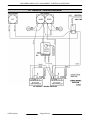
36" GRIDDLE - WIRING DIAGRAM
36" GRIDDLE - WIRING DIAGRAM
Page 21 of 24
F45514 (0214)
RRG SERIES HEAVY DUTY GAS GRIDDLE - ELECTRICAL OPERATION
48" GRIDDLE - WIRING DIAGRAM
48" GRIDDLE - WIRING DIAGRAM
F45514 (0214)
Page 22 of 24
RRG SERIES HEAVY DUTY GAS GRIDDLE - ELECTRICAL OPERATION
60" GRIDDLE - WIRING DIAGRAM
60" GRIDDLE - WIRING DIAGRAM
Page 23 of 24
F45514 (0214)
RRG SERIES HEAVY DUTY GAS GRIDDLE - TROUBLESHOOTING
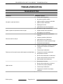
TROUBLESHOOTING
TROUBLESHOOTING
PROBLEM
POSSIBLE CAUSES
No spark to ignite pilot burner.
Spark at ignitor but pilot burner does not light.
Pilot burner will not stay lit.
1.
Power switch inoperative.
2.
No power to ignition module.
3.
Ignition module not properly grounded
4.
Ignition module malfunction.
5.
Spark gap incorrect.
6.
Ignitor/flame sense wire inoperative.
1.
No power to single solenoid valve.
2.
Single solenoid valve malfunction.
3.
Gas supply off or insufficient.
1.
Spark/flame sense wire connections
incorrect.
2.
Improper ground on pilot burner.
3.
Ignitor/flame sense malfunction.
4.
Gas pressure not within specified range.
5.
Pilot flame needs adjusted.
1.
Power to temperature controller incorrect.
2.
Temperature controller not calibrated
correctly.
3.
Thermocouple malfunction.
Pilot burner is lit but main burners will not light or maintain flame. 4.
5.
High/Low heat.
F45514 (0214)
Page 24 of 24
Temperature controller malfunction.
Gas pressure incorrect.
6.
Burner orifice obstructed or malfunction.
7.
Power to dual solenoid valve incorrect.
8.
Dual solenoid valve malfunction.
1.
Gas pressure incorrect.
2.
Burner orifice malfunction or incorrect.
3.
Air shutter not properly adjusted.
4.
Thermocouple malfunction.
5.
Temperature controller not properly
calibrated.