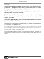
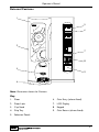
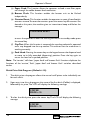
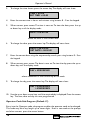
1
M A N U A L
O P E R AT O R ’ S
Profile & Contour ®
Part No. PR09682000
Issue 2 02/02
Operator’s Manual
Contents
Page No.
Introduction ...................................................................................................2
Important Safeguards ...................................................................................2
Features...........................................................................................................3
Specifications..................................................................................................4
External Features ..........................................................................................5
Internal Features ...........................................................................................6
Installation Procedure ..................................................................................7
Connecting the Water Supply....................................................................8
Connecting the Electricity Supply.............................................................8
Setting Up .......................................................................................................9
How to Vend a Drink ................................................................................11
Daily Cleaning and Re-filling.....................................................................12
Coffee Brewer Maintenance ....................................................................17
Tea Pot Brewer Cleaning ..........................................................................18
Operator Functions ...................................................................................19
Problem Solving ..........................................................................................30
De-commissioning the Machine ..............................................................31
Recommended Spares List .......................................................................32
The following symbol is used throughout this Operator’s Manual:
Safety First! Take care, risk of personal injury.
© Copyright 2002 Crane Merchandising Systems
1
Operator’s Manual
Introduction
This manual provides a guide to the daily operation, basic cleaning and maintenance
tasks and operator accessible programming functions of the Profile and Contour®
range of table-top vending machines and indicates when the operator should call a
qualified service engineer for assistance.
Important Safeguards
When using the machine, always have this manual available for quick and easy reference
and always follow these basic safety precautions:
1.
Read all instructions before using the machine and ensure that anyone who will
be involved with the cleaning or refilling of the machine also reads the
instructions.
2.
The machine should be situated on a strong horizontal surface, at a convenient
height and in a position where it is not likely to be knocked off.
3.
The mains lead should never trail from the machine and should always be kept
away from hot surfaces and sharp edges.
4.
Do not operate the machine if any part is damaged, e.g. mains lead, until it has
been checked by a qualified Service Technician.
5.
Allow the machine to cool before handling or moving.
6.
Never immerse the machine in water, or any other liquid and never clean it with
a water jet.
7.
If the machine should accidentally freeze up, call a Service Technician to check it
before switching on.
8.
Ensure that you are conversant with the ‘Health and Safety at Work and Electricity
at Work Regulations 1989’.
ALWAYS DISCONNECT THE MACHINE FROM THE MAINS ELECTRICITY
SUPPLY BEFORE CLEANING AND SERVICING.
This machine is for indoor use only and because it is a food machine, should be sited
in a clean, hygienic area.
It is recommended that this equipment is serviced by a trained Service Technician.
2
Operator’s Manual
Features
The Stentorfield Profile and Contour® table-top machines from Crane Merchandising
Systems, offer a complete range of hot drinks including Freshbrew Tea and Coffee,
Decaffeinated Coffee, Cappuccino, Espresso and Chocolate.
The LCD display, which provides information regarding selection and pricing, enables
the user to obtain a drink easily and quickly.
The Microprocessor Control System provides an automatic hot and cold flushing
facility, fault condition messages and a key operated jug facility, ensuring complete
reliability and flexibility.
Up to twelve independent drink prices are available. Alternative prices and free vend
periods are available on all selections.
Full cost control is maintained via the audit facility. This provides precise information
on drink counts and ingredients used.
It is the policy of Crane Merchandising Systems to continue developing its range of
beverage equipment.The information presented within this document is for information
only and may be changed without prior notice.
Crane Merchandising Systems accepts no responsibility for damage caused to the
equipment through misinterpretation or misuse of the information contained in this
manual.
3
Operator’s Manual
Specifications
Profile
Contour
Height
985 mm
985 mm
Depth
590 mm
590 mm
Width
540 mm
660 mm
Weight
105 kg
184 kg
Electrical Services
(i) Voltage
(ii) Current
(iii) Frequency
Water Services
(i) Pressure
(ii) Stopcock
Cup Capacity
Cup Type
Coin Mechanism
220 - 240 Volts AC
13 Amp Fused
50 Hz
100 Kpa (1 Bar) - 800 Kpa (8 Bar)
15 mm BSP from rising main
350 (when using 7oz squat cups)
7oz squat, 7oz tall and 9oz tall versions of the HIPS vending cup
may be used although modification to the machine will be
required to change between cup types
Coin mechanisms and cashless card systems*
can be fitted on request
* An external fitment is required to enable the Profile machine to support cashless operation
All weights and dimensions are approximate and are for guidance only.
Water Filter - External Fitment (where fitted)
The machine may be fitted with either an Everpure or Brita filter head and filter
cartridge. This unit will be located either within the machines base cabinet (where
applicable) or in the water supply line.
To maintain optimum drink quality, the cartridge should be replaced every six months
or earlier, depending upon the number of vends.
4
Operator’s Manual
External Features
1
5
6
2
7
8
3
9
4
Note: Illustration shows the Contour.
Key:
1.
Door
6.
Coin Entry (where fitted).
2.
Door Lock
7.
LCD Display
3.
Cup Stand
8.
Keypad
4.
Drip Tray
9.
Coin Return (where fitted)
5.
Selection Decals
5
Operator’s Manual
Internal Features
12
11
10
9
1
8
2
7
3
4
5
6
Note: Illustration shows Contour interior.
Key:
1. Coffee Canister (Freshbrew
machines only)
7. Mixing System
2. Coffee Brewer (Freshbrew machines
only)
9. Large Ingredient Canister
3. Tea Brewer (Freshbrew Contour
machines only)
4. Large Freshbrew Waste Bucket
5. Small Freshbrew Waste Bucket
6. Drip Tray Grill
6
8. Cup Turret
10. Door Switch
11. Filter Paper Roll (Freshbrew
machines only)
12. Small Ingredient Canister
Operator’s Manual
Installation Procedure
Important!
It is essential that personnel responsible for installing, commissioning and servicing the
machine understand the following:
1. The installation and commissioning of the machine should only be carried out by
trained and authorised service engineers.
2. All water and electrical services must be correctly and safely connected.
3. All covers should be replaced correctly and securely and the machine left in a safe
condition.
4. The machine is suitable for indoor use only, sited in an area with a recommended
ambient temperature not below 10º C and not exceeding 30º C.
5. Prior to moving the machine to its location, ensure that there is sufficient access
space available via passageways, stairs, lifts, etc and that the table/counter where the
machine is to be located is strong enough to safely support its weight. (Refer to
Specifications Table).
6. The machine should be located near the appropriate water and electrical services
as detailed in the specification table.
7. To ensure adequate ventilation, 100 - 150 mm (4 - 6 inches) clearance must be
allowed between the back of the cabinet and the wall.
8. Open the cabinet door. Remove all transit packing and the installation kit from the
machine. Check for visual signs of damage which may have occurred during transit.
9. If the machine is damaged or any parts are missing, you must contact the supplier
immediately.
10. Ensure that the machine is levelled in both front to back and side to side planes
using the adjustable levelling feet.
7
Operator’s Manual
Connecting the Water Supply
1. The machine should be situated within 1 metre of a drinking water supply from a
rising main, terminating with a W.R.C. approved 15mm compression stop tap.
2. The water supply should comply with both the Statutory Instrument No.1147 “Water, England and Wales” and The Water Supply (Water Quality) Regulations
1989.Water pressure at the stop tap must be within the limits 1 - 8 Bar (100 Kpa - 800
Kpa).
3. Connect the flexi-hose supplied with the machine to the stop tap ensuring that the seal
supplied is fitted correctly. Flush the system via the stop tap (several gallons) before
connecting the hose to the machine.
4. Connect the hose to the inlet valve located on the rear of the machine. Ensure that the
seal is correctly fitted. Ensure that all water supply fittings are tight.Turn on the stop tap
and check for leaks.
Connecting the Electricity Supply
Safety First! THE MACHINE MUST BE EARTHED. ON NO ACCOUNT
SHOULD IT BE EARTHED TO THE WATER SUPPLY PIPE
The machine must be connected to a 240 Volt 50Hz 13 amp fused switched socket
outlet, installed to the latest edition of the IEE regulations, using a 3 pin BS approved
13 amp fused plug.
Important: If the mains lead becomes damaged in any way it must be replaced by a
special lead available from the manufacturer.
8
Operator’s Manual
Setting Up
The following procedure must be carried out by a trained installation engineer before
the machine can be used for the first time.
1. Ensure that the electrical and water services to the machine are connected
correctly and turned on. Ensure that the waste tray is fitted correctly to the
machine.
2. Open the front door of the machine. Insert the safety key supplied with the machine
into the door switch.The machine is now on.
3. Whilst the boiler in the machine is filling, the display will show the message:
SORRY NOT IN USE
LOW WATER
4. As the water in the boiler starts to heat, the message on the LCD will change to:
SORRY NOT IN USE
WATER HEATING
5. Ensure that no water overflows from the boiler tank overflow pipe into the waste
tray. Check the system for leaks.
Safety First! Should the machine fail to fill correctly or leak, turn off the
stopcock and contact the machine supplier for assistance.
6. Check the LCD display on the front of the machine to ensure that the water has
heated to the correct temperature and that the machine is in standby mode. The
display will show the message:
PLEASE SELECT DRINK
TIME XX:XX
Where XX:XX is the current time.
7. Loading the cup turret. Swing the cup turret assembly out of the machine and
remove the lid. Fill the tubes with the correct size cups for the type of cup turret
fitted to the machine.
Important: Do not fill the tube directly above the cup dispense position. Allow
the cup turret to rotate a full tube to the cup dispense position. Rotating the cup
turret by hand will damage the mechanism.
9
Operator’s Manual
Allow the cups to drop into the tubes directly from the packaging. DO NOT
TOUCH THE CUPS WITH YOUR HANDS. Replace the cup turret lid.
8. Remove the ingredient canisters - DO NOT place ingredient canisters on the floor.
Remove the lids from the ingredient canisters. Fill the canisters with the correct
ingredients, re-fit the lids and re-fit canisters into machine.
9. Return the cup turret assembly to its operating position. Ensure that the unit locks
into place.
Freshbrew models only, proceed with steps 10 and 11
10. Remove the pin from the filter paper holder. Load the filter paper roll (provided in
the installation kit) onto the support. Replace the pin.
11. Press and release the paper feed switch, located in the switch panel on the rear
of the door, to operate the brewer.When the brewer chamber reaches its fully open
position, remove the safety key from the door switch to switch off the power to
the machine.
Remove the brewer cover. Carefully feed the filter paper under the raised chamber
and through the feed wheels. Refit the brewer cover.
Replace the safety key into the door switch to restore power to the machine.The
filter paper will index automatically and the brewer chamber will return to the
closed position.
Whilst this operation is taking place the display will show the message:
BREWER REPOSITIONING
PLEASE WAIT
12. Press the cup test switch, located in the switch panel on the rear of the door, to
index the cup turret mechanism to the first available full cup stack. Ensure that the
cup drop mechanism operates correctly.
13. Operate the machine through its complete range of vends to ensure that each vend
is correctly dispensed. Place an empty cup under the dispense head for each
selection. Remove the safety key and close the cabinet door. Ensure that the
machine is left in a clean and safe condition.
10
Operator’s Manual
How To Vend A Drink
1. Insert sufficient credit to cover cost of drink
choice (where applicable).
Press the number combination on the keypad
for the drink of your choice followed by a
strength option if required.
2. Cup will drop into the cup catcher and dispense
head will move into dispense position.
The drink will now be delivered into the cup.
3. The dispense head returns to its parked
position and the display will tell you when your
drink is ready.
Remove the cup carefully from the cup catcher.
Press the coin return button situated next to
the coin entry to receive any change owed.
4. To vend a drink into your own cup, lower the
cup stand to horizontal position. Place your cup
on the stand.
Select a drink as described above. Press the *
(star) key before pressing the drink selection
number on the keypad.
Remove your cup and raise the cup stand into
its vertical position.
11
Operator’s Manual
Daily Cleaning and Re-filling
The quality of drinks produced by Profile and Contour® machines can only be
maintained if the machine is cleaned regularly following the schedule outlined. Before
carrying out the daily cleaning procedure described on the following pages, it is
recommended that you have the following materials to hand:
❍ Bactericidal Cleaner
❍ De-Staining Agent
❍ Cleaning Cloths
❍ Paper Towels
❍ Small Brush
❍ Two Large Buckets
❍ Disposable Gloves
Bactericidal Cleaner
This can either be a liquid or powder agent which should be dissolved in clean water
in accordance with the instructions on the product packaging. The solution should be
used for cleaning machine components and wiping surfaces during the cleaning
operation.
De-Staining Agent
This is a liquid or powder agent which should be dissolved in clean water in accordance
with the instructions on the product packaging. The solution can be used on heavily
soiled or stained components such as buckets and drip trays. Items or surfaces cleaned
with this solution must be rinsed in clean water to remove traces of the cleaning agent.
Liquid Destainer - Brewer Units
Crane Merchandising Systems recommends that a liquid destaining product is used for
cleaning the brewer units fitted to Profile and Contour® machines.The product must
be user in accordance with the instructions on the product packaging, following all
health and safety guidelines. Detailed procedures for cleaning coffee and tea brewer
units fitted to the machines are outlined on pages 17 and 18 of this operator’s manual.
It is necessary to carry out the cleaning and maintenance procedure outlined on the
following pages on a regular basis, either at the end of the day or at the start of the
day before the machine is in constant use.
12
Operator’s Manual
1.
On arrival at the machine, open the door. Fill a
cleaning bucket with hot water and dilute the
bactericidal cleaner in accordance with the
instructions on the product packaging.
Swing the cup turret assembly out of the machine
in order to gain access to the ingredient canisters.
Remove the ingredient canisters. DO NOT PLACE
THEM ON THE FLOOR.
2.
Remove the canister shelf and extract tray.
Using a dry brush, clean the area under the extract
tray.
Wipe the upper interior of the machine. Clean the
extract tray and refit into machine.
3.
Remove steam hoods (a) and mixing bowls (b) from
whipper bases (c).
Remove the dispense pipes (d) from the whipper
bases (c) and the plastic dispense block.
Remove the plastic thumb-screw securing the
plastic dispense block to the dispense head
assembly. Remove the dispense block and clean
thoroughly with the mixing system components.
4.
Remove the complete whipper unit (a), including the
whipper base as shown.
Split the whipper unit into separate parts - whipper
base, mixing chamber and impeller.
Clean all of the mixing parts, including the steam
hoods and mixing bowls thoroughly in the diluted
bactericidal cleaner solution.
Rinse all components with clean water and dry
thoroughly before refitting to machine.
13
Operator’s Manual
5.
Refit the whipper bases (a). Rotate the base anticlockwise to lock into position as shown.
Refit the impeller's (b). Line up the dot on the
impeller with the flat on the motor shaft.
a
b
Refit mixing chambers, mixing bowls, steam hoods
and dispense pipes.
6.
Refit the dispense pipes to mixing chamber outlets.
Refit the plastic dispense block to the dispense head
assembly. Secure with the plastic thumb screw (a).
Ensure that the dispense pipes are located into their
correct positions in the dispense block as shown in
the illustration.
a
7.
With a damp sanitised cloth, remove any ingredient
on the exterior of the canisters, including any
product build-up around the canister outlets.
Check ingredient canisters and refill if required.
Refit the canisters into the machine from left to
right. Ensure that the canisters are refitted correctly.
Weekly: Empty and wash the ingredient canisters.
Dry thoroughly, refill and refit into machine.
8.
Remove the freshbrew waste bucket(s), where
fitted, from the machine.
Empty the contents, clean and refit to machine.
14
Operator’s Manual
9.
Remove the drip tray from the machine. Empty and
clean.
Clean around the cup station area with a damp
sanitised cloth.
Wipe down the interior of the door. Clean the base,
sides and back of the machine.
Replace the drip tray.
10. Undo the thumb screws and remove cup throat
complete with drain pipe (a).
Clean cup throat and pipe in the sanitiser solution.
Rinse components with clean water and dry
thoroughly.
Reassemble to machine ensuring that drain pipe is
correctly located through drain hole.
11. Check the levels of the cups in the cup stack.Where
necessary, remove the cup stack lid and fill.
Important: Do not fill the tube directly above the
cup dispense position.Allow the cup turret to rotate
a full tube to the cup dispense position. Rotating the
cup turret by hand will damage the mechanism.
DO NOT TOUCH THE CUPS WITH YOUR
HANDS.Allow the cups to drop into the cup stack
directly from the packaging. Replace lid.
12. Un-lock the cashbox (where fitted); remove and
empty.
Refit the cashbox to the machine, turning the lock
to secure.
15
Operator’s Manual
13. Remove the coin mechanism cover (where fitted).
Wipe the inside of the coin mechanism with a damp
cloth.
Check the coin tubes and refill as required.
14. Restore power to the machine using the safety key
as shown in the illustration.
Press the program entry switch, located in the
switch panel on the rear of the door and enter the
correct operator code - selection button 1 followed
by 7.
Proceed as follows:(i)
Press the flush switch and check that all of the
mixing stations are water tight.
(ii) Using the service switch, test vend each drink
selection.
(iii) Press the view counters switch and record
the audit information.
Remove the safety key and close the door.
Clean and buff the outside of the machine.
16
Operator’s Manual
Coffee Brewer Unit Maintenance
At least twice a week the coffee brewer unit must be removed from freshbrew
machines and cleaned.
Safety First! Never clean or service the brewer unit while it is in motion as
fingers may become trapped in the mechanism.
Referring to the diagram, proceed as follows:1.
Open the front door of the machine. Remove the
paper/waste ingredient guard.
2.
Switch on the power using the door switch safety
key.
3.
Press and release the paper feed switch to index
the brewer to its fully open position.
4.
When the brewer reaches its fully open position,
remove the safety key to switch off the power.
5.
Tear the filter paper above the brewer (a). Remove
the used paper from the brewer unit.
6.
Remove the brewer dispense pipe from the dispense head.
7.
Pull down the brewer release pin (b) and carefully lift the brewer unit up and clear
of its locating bracket.Thoroughly clean the external surfaces of the brewer.
8.
With the brewer unit removed from the machine, clean the area surrounding its
locating bracket. Refit brewer to machine and refit the outlet pipe to the dispense
head.
9.
Switch on the power using the door switch safety key.The brewer chamber will
return to its closed position.
10.
Pour 2-3 full cap measures of de-staining fluid directly into the top of the brewer
chamber. Flush the brewer using the brewer flush facility a minimum 4 times.
11.
Press and release the paper feed switch to index the brewer to its fully open
position. Remove the door switch safety key to switch off the power to the
machine.
12.
Feed the filter paper through the paper feed mechanism. Switch on the power to
the machine using the safety key. Filter paper will index automatically and the
brewer chamber will return to its closed position. Refit brewer guard.
13.
Remove the brewer waste bucket and empty the contents. Clean waste bucket
and refit. Remove the safety key and close the door.
a
b
17
Operator’s Manual
Tea Pot Brewer Cleaning
At the same time as the coffee brewer is being cleaned, the tea brewer (where fitted)
should also be removed and cleaned.
Safety First! Never clean or service the tea pot brewer unit while it is in
motion as fingers may become trapped in the mechanism.
Referring to the illustrations, proceed as follows:1.
Remove the tea pot bowl and mounting bracket
assembly from the machine.
Clean all parts of the tea pot bowl assembly and
mounting bracket using the liquid destaining agent.
Follow the instructions for soak cleaning on the
product packaging.
Rinse all components with clean water and dry
thoroughly.
2.
Undo the thumb screw retaining the brewer unit.
Remove the complete brewer unit from the
machine as shown.
3.
Split the brewer unit into its separate parts as
shown.
b
Rinse all components in clean water, dry
thoroughly and refit to machine.
c
Re-fit tea pot bowl/mounting bracket assembly.
18
a
Clean bowl (a), gauze (b) and outlet (c) using the
liquid destaining agent. Follow the instructions for
soak cleaning on the product packaging.
Operator’s Manual
Operator Functions
Programming Mode
To access the Programming mode you need to enter a sequence of key strokes on the
front panel.The time between each key stroke must be less than 5 seconds otherwise
the machine will return to standby mode. Once in Programming mode, there is no time
constraint.
Programming mode utilises the front panel keys, as defined in Figure 1, in order to enter
values and commands.
Figure 1
During programming the keys are used as follows:
Buttons 0-9
‘C’
‘Blank’
Used for entering data
Used for correcting data
For moving to a higher programme level
▲
(Strong) For indexing up in a programme, or incrementing data
▼
(Mild) For indexing down in a programme, or entering data
‘Normal’
For entering data in a programme, or moving to a lower
programme
N.B. In the following programming section, the ‘normal’ key will be referred to as the
access key, the ‘strong’ key as the up (▲) key and the ‘mild’ key as the down (▼)
key.
19
Operator’s Manual
Accessing the Programming Mode
1.
Press the program entry switch, mounted in a panel inside the top of the door,
followed by the Operator’s Access Code - selection button 1 followed by 7. Code
entry errors may be erased using the cancel (C) key.
2.
With the correct code entered the title of the first sub-program will be displayed
on the LCD.The LCD will display the message:
FOR SERVICE
PRESS ACCESS
3.
To step through the sub programs, press either the up (▲) or down (▼) keys.
4.
To access a displayed sub program, press the access (normal) key.
5.
If any numerical data parameter is entered, it may be changed in one of two ways:
(a) Pressing the up (▲) or down (▼) keys increases or decreases the number on
each key press.
(b) Keying in the actual digits of the number required. Using this method, the new
number will be displayed in place of the current parameter.
6.
Once the correct number has been entered, press the access key to overwrite
the old parameter with the new number.To retain the old parameter press either
the ‘blank’ or cancel (C) key.
Note: It is not possible to vend a drink in Programming mode.
20
Operator’s Manual
Function Switches
Profile and Contour® machines are fitted with 3,
two position rocker switches, mounted in a panel
inside the top of the door.
These switches are used for the following functions:
Program Entry Switch
This switch allows the operator to access the
operator’s program. Once pressed, enter the
Operator’s Access Code (selection button 1
followed by 7) from the keypad.
Paper Feed Switch (Freshbrew Models)
This switch allows the operator to feed a new paper roll through the coffee brewer.
When the switch is pressed and released, the brewer will index to its fully open position
and stop.The operator can then safely feed the filter paper through the brewer’s paper
feed mechanism. Pressing and releasing the paper feed switch again will cause the filter
paper to index automatically and the brewer chamber will return to its closed position.
Flush Switch
1.
The Flush sequence operates automatically and flushes the complete water
system. Before the sequence begins, the system waits until the water is at the
correct temperature determined by the thermostat. During the entire sequence,
the LCD displays the message:
SORRY NOT IN USE
SELF CLEANING
2.
In order to guarantee the highest standards of cleanliness, the boiler fill valve is
disabled, ensuring that the water used in the sequence is delivered at the optimum
temperature to kill any micro-organisms. Each hot water valve and the
corresponding whipper is switched on in sequence for a pre-set flush time.
3.
Once the flush cycle is complete, the boiler refills and when the water is at the
correct temperature, the machine returns to standby mode, ready to vend.
4.
To flush the machine:
Caution: Ensure that the waste tray is empty (and in place) and keep hands away
from the dispensing area whilst the flushing cycle is in operation.
21
Operator’s Manual
a.
Open the front door of the machine and insert the safety key.
b.
Press and release the flush switch.
c.
Empty the waste tray when complete.
Brewer Flush Switch (Freshbrew Models)
1.
The brewer flush switch allows the brewer to be flushed independently. In order
to guarantee the highest standards of cleanliness, the boiler fill valve is disabled,
ensuring that the water used is delivered at the optimum temperature to kill any
micro-organisms.
2.
The brewer unit is filled with hot water and then operated through four complete
brew cycles.
3.
Once the flush cycle is complete, the boiler refills and when the water is at the
correct temperature, the machine returns to standby mode, ready to vend.
4.
To flush the machine:
Caution: Ensure that the waste tray is empty (and in place) and keep hands away
from the dispensing area whilst the flushing cycle is in operation.
a.
Open the front door of the machine and insert the safety key.
b.
Press and release the brewer flush switch.
c.
Empty the waste tray when complete.
View Counters Switch
1.
Internal counters monitor the numbers of vends of each drink type, the number
of jug vends, free vends and the weights of each of the ingredients used.
2.
To view the counters:
a.
Open the front door of the machine.
b.
Press and release the view counters switch.
c.
Step through the list using the ▲ and ▼ keys on the front panel.
d.
When complete, press the ‘Blank’ or cancel (C) key to return to standby
mode.
Service Switch
Pressing the service switch allows the operator to make one free test vend using the
keypad on the front of the machine to ensure that the machine is operating correctly.
Drinks vended using the service switch are recorded in the vend counters.
22
Operator’s Manual
Sub Programs
The 10 sub programs within the Operator’s Program are shown in the following
diagram - figure 2.
Figure 2
To access a sub program within the Operator’s Program, enter the programming mode
as described previously.To step through the sub programs, press either the up (▲) or
down (▼) keys.To enter a displayed sub program, press the access key.
Operations Sub-Program
Upon entry into the operations sub program, pressing the access key on the keypad
will display the ‘Service’ function. Pressing the access key again will carry out the
function described.To move to the next function, press the up (▲) or down (▼) keys.
To return to the main menu, press the cancel (C) key.
The operations sub-program is split into seven separate functions:
(a) Service: When accessed, this function allows the operator to test vend each
drink selection, for example after carrying out the cleaning procedure.
(b) Self Clean: This function allows the operator to program two periods
during the day when the machine will automatically flush through the entire
water system.
23
Operator’s Manual
(c) Paper Feed: This function allows the operator to feed a new filter paper
roll through the coffee brewer feed mechanism.
(d) Brewer Flush: This function enables the brewer unit to be flushed
independently.
(e) Counter Reset: This function enables the operator to reset all vend/weight
counters to zero.To reset the counters, press the access key.All counters are
cleared at this point, the machine gives an intermittent beep and flashes the
message:
COUNTERS RESET
to warn the operator.To clear the warning and return to standby mode, press
the cancel key.
(f) Cup Test: When this function is accessed, the cup drop solenoid is operated
and a cup dropped into the cup catcher.This ensures that the mechanism is
working correctly.
(g) Park Head: Pressing the access key on the keypad causes the dispense head
to move to its fully extended (dispensing) position. Press the key again to
return the head to its parked position.
Note: The ‘service’, ‘self clean’, ‘paper feed’ and ‘brewer flush’ functions duplicate the
functions of the ‘service’, ‘flush’, ‘paper feed’ and ‘brewer flush’ switches described
earlier.
Drink Price Sub-Program (Default = 10)
1.
The drink price sub-program allows the normal tariff prices to be individually set
for each drink.
2.
Upon entry into this sub-program, the name of the first drink (Coffee) is displayed,
followed by its price.The LCD will display the following message:
COFFEE
PRICE = 10
3.
To alter the drink price, press the access key. The LCD will display the following
message:
COFFEE
PRICE > 10
24
Operator’s Manual
4.
The = symbol changes to a > symbol indicating that it is now possible for new
data to be entered. Key in the new price using the keypad and when correct press
access to overwrite the old data.
5.
The prices for other drinks can now be set following the sequence described in
the previous “Programming Mode” section.
Alternative Tariff 1 Sub-Program (Default = 15)
This sub-program works in exactly the same way as the drink price sub program
and has the same appearance. The prices set in this program will be in force during
tariff 1 periods.
Alternative Tariff 2 Sub-Program (Default = 20)
This is identical to the alternative tariff 1 sub-program except that the prices set
here will be in force during tariff 2 periods.
Alternative Price Period Sub-Program
This sub-program enables the times to be specified when each of the above tariffs
should be in force.There is a four level tariff structure available:
1. Normal Tariff:
This relates to prices set in the drink price sub-program and in force when no
alternative price period is currently applicable.
2. Tariff 1:
Prices set in the tariff 1 price sub-program.
3. Tariff 2:
Prices set in the tariff 2 price sub-program.
4. Tariff 0:
Sets the machine into free vend.
The machine is factory set to the normal tariff, with no alternative prices available.To
change the tariff period, proceed as follows:1.
On entry into the sub-program the display will show the message:
P1 = 00:00 - 00:00
TARIFF - EVERY DAY
25
Operator’s Manual
2.
This is an empty price period.To enter a price period (e.g. 10:30 - 15:45,Tariff 2,
Weekends), press access.The display will now read:
START > 00:00
Note: The arrow symbol (>) indicates that it is possible to update the display.
3.
Enter the correct start time in hours and minutes using buttons 0 - 9 on the
keypad.
Note: To correct any entry errors, press cancel to delete the last digit entered.
Pressing cancel with no digits displayed will exit to the Operator’s program.
4.
With the start time entered press access. Enter the finish time as described above
and press the access key.The display will now show:
PERIOD 10:30 - 15:45
TARIFF > 0
5.
To set the tariff period, enter a number between 0 and 2 (or use the up (▲) or
down (▼) keys) followed by access.The message will change to:
PERIOD 10:30 - 15:45
TARIFF 2 > EVERYDAY
6.
Using the up (▲) and down (▼) keys, index the day setting between “Every day”,
“Weekdays” and “Weekends”. When the required day setting is displayed, press
the access key to complete the price period data entry. The message on the display
will read:
PERIOD 10:30 - 15:45
TARIFF 2 EVERYDAY
7.
There are a maximum of ten possible price periods available. To enter another
price period, use the up (▲) or down (▼) keys to view the periods until an empty
period is displayed. The new period is entered in the same way as described
previously.
8.
If the start time is entered as being a later time than the finish time, the period
will not be accepted by the machine. If periods overlap, the first overlapping period
in the list will be the one in force until it has finished. To delete a period, continue
as if that period were to be re-programmed, and when the display is requesting
the start time to be entered, press cancel.
26
Operator’s Manual
Vend Counters Sub-Program
1.
When the vend counters sub-program is entered, the first drink counter is
displayed:
COFFEE
1372
2.
The up (▲) and down (▼) keys enable the counters for each drink to be viewed,
and values noted, but they cannot be altered using the keypad.These counters can
only be reset by using the ‘reset counters’ function within the “operations subprogram”.
3.
There is one vend counter for each drink, plus counters for jug vends, free vends,
total vends and total sales value.The total sales data is displayed in units of 1 penny.
Weight Counters Sub-Program
1.
The weight counters sub-program operates in exactly the same way as the vend
counters sub-program with the LCD displaying the weights of individual
ingredients used.Weights are displayed in units of one kilogram.
2.
There is one weight counter displayed for each ingredient allocated to a canister
in the canister configuration sub-program.These counters are reset using the using
the ‘reset counters’ function within the “operations sub-program”.
Time/Date Sub-Program
The machine maintains a record of the current time and date in 24-hour format. The
date is programmed for leap-year roll-over and should not require adjustment.
To set the time and date, proceed as follows:
1.
The Time/Date sub-program displays the time, date and day of the week. The up
(▲) and down (▼) keys are used for viewing the three different messages.
2.
To view the time, enter the time/date sub-program. The display will show the
message:
TIME = XX:XX
where xx:xx is the current time.
27
Operator’s Manual
3.
To change the time shown, press the access key.The display will now show:
TIME = XX:XX
SET TIME > 00:00
4.
Enter the correct time in hours and minutes using buttons 0 - 9 on the keypad.
5.
When correct, press access. The time is now set. To view the date, press the up
or down key until the display reads:
DATE = XX:XX:XX
where xx:xx:xx is the current date.
6.
To change the date, press the access key.The display will now show:
DATE = XX:XX:XX
SET DATE > 00:00:00
7.
Enter the correct date using the sequence day, month, year using buttons 0 - 9 on
the keypad.
8.
When correct, press access.The date is now set.To view the day, press the up or
down key until the display reads:
DAY = XXXXXXXXX
where xxxxxxxxx is the current day of the week.
9.
To change the day, press the access key.The display will now show:
DAY = XXXXXXXXX
> XXXXXXXXX
10. Use the up or down arrow keys until the required day is displayed. Press the access
key. The time, date and day are now programmed.
Operator Code Sub-Program (Default 17)
Entry into the Operator code sub-program enables the operator code to be changed.
This code may be of any length up to seven digits. Enter a new code at the prompt
and when correct press the access button.
28
Operator’s Manual
Jug Code Sub-Program
1.
The jug code is a two digit security code that when entered correctly via the
keypad, followed by a two digit drink selection number, allows a jug to be vended.
Entry into the jug code sub program allows the operator to set a unique jug code.
2.
Access the jug code and enter a new code using buttons 0-9 on the keypad. Press
access to overwrite the old code.
29
Operator’s Manual
Problem Solving
In the unlikely event of the machine developing a problem, details are given in the table
below (figure 3) on how to deal with common faults that can be easily remedied by
the operator.
Safety First! Should the remedy given below not cure the problem, or the
fault is not listed, DO NOT ATTEMPT TO CURE THE FAULT YOURSELF.
Contact your machine supplier for assistance.
Figure 3
Fault
Possible Cause
Remedy
Waste tray overflowing
Level sensor incorrectly
located or jamming
Ensure sensor is placed
correctly in the tray
Incorrect drinks
dispensed
Ingredient canisters
located incorrectly
Refit canisters into their
correct positions
Leaking from dispense
area
Mixing bowls/chambers
fitted incorrectly
Refit correctly and ensure
that all mixing stations
are water tight
Low water showing
on LCD display
Water supply
turned off
Ensure water supply is
turned on at stop-tap
Blank LCD display
Electricity supply
turned off
Ensure electricity supply
is turned on at the mains
Cups jamming
Incorrect cup size
Remove cups from cup
turret and replace with
correct size cups
No change given
from change-giver
(where fitted)
(i) Coin tubes jamming
Clear coin tubes and
check for blockage
(ii) Coin tubes empty or
below pre-set level
Check and refill coin tubes
where necessary
(i) Incorrect paper fitted
Remove and fit correct
90mm filter paper
(ii) Filter paper loaded
incorrectly
Reload paper and ensure
that it feeds correctly
(iii) Paper fouling on
brewer guard
Adjust brewer guard.
DO NOT REMOVE
Coffee brewer unit
jamming
30
Operator’s Manual
Machine Leaking
Should the machine develop a leak, switch off the mains water supply at the stop-tap
and if safe to do so, switch off the mains electricity supply. Contact your machine
supplier for further assistance.
Safety First! Do not attempt to repair the machine yourself.
De-Commissioning the Machine
Should the machine need to be shut down for short periods, for example over a long
weekend, no special treatment is required.The machine should be thoroughly cleaned
before the site is closed down and on return it is advisable to vend each drink type to
ensure correct operation and to “freshen up” the machine.
If the machine is to be moved or transported, remove all ingredients and thoroughly
clean the machine. If a coin module is fitted, remove any cash from the coin tubes and
cash box. Disconnect all electricity and water supplies.
The machine should be transported upright at all times. Contact the supplier of the
machine for assistance.
31
Operator’s Manual
Recommended Spares List
The spares items listed below are available from your machine supplier.
10
11
12
13
14
9
15
2
8
3
16
7
1
4
5
6
18
17
Ref. No.
1
2
3
4
5
6
7
8
9
10
11
12
13
14
32
Part No.
(i) PL01971000
(ii) PL02460000
SI01295000
SI01986000
PL01970000
(i) PL02275000
(ii) PL02495000
SI01171960
(i) PL01967000
(ii) PL02458000
(i) PL01966000
(ii) PL02457000
PL01313000
WF01176000
ME01849000
PL02266000
PL04407000
PL02712000
Item Description
Whipper Base - Grey
Blind Whipper Base - Black
O Ring Seal
Seal
Impeller
Mixing Chamber - Grey
Mixing Chamber - Black
Silicon Pipe
Mixing Bowl - Grey
Mixing Bowl - Black
Steam Trap - Grey
Steam Trap - Black
Canister - Tall
Filter Paper Roll
Retaining Clip
Canister - Short
Canister Lid - Rectangular
Canister Lid - Square
Operator’s Manual
Ref. No.
15
16
17
18
Part No.
(i) PL01795000
(ii) PL04607000
(i) PL01128000
(ii) PL01441000
(iii) PL01442000
MT05429000
PL05189000
Item Description
Freshbrew Coffee Canister - Square
Freshbrew Tea Canister - Square
Canister Chute
Canister Chute - LH
Canister Chute - RH
Drip Tray Grill
Drip Tray
33
Operator’s Manual
Notes
34
Operator’s Manual
Notes
35
Operator’s Manual
Notes
36
Pipsmore Park, Bumpers Farm Industrial Estate,
Chippenham,Wiltshire SN14 6NQ
Tel: +44 (0)1249 444807 Fax: +44 (0)1249 444819
Email: [email protected] Website: www.cranems.co.uk