1
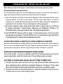
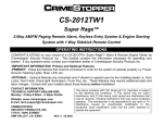
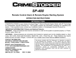
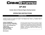
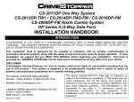
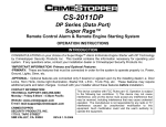
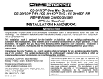
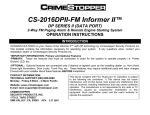
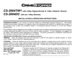
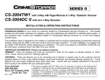
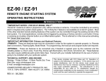
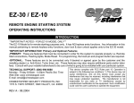
CS-2012DPII-TW1
Super Rage™
2-Way FM/FM Paging Remote Alarm, Keyless Entry System & Engine Starting
System with 1-Way Sidekick Remote Control
OPERATING INSTRUCTIONS
CONGRATULATIONS on your choice of a CS-2012DP-TW1 Super Rage™ Alarm & Remote Engine Starter
by Crimestopper Security Products Inc. This booklet contains the information necessary for operating your
system. If any questions arise, contact your installation dealer or Crimestopper Security Products Inc.
*IMPORTANT INFORMATION: Primary and Optional Features
-PRIMARY: These are features that must be connected in order for the system to operate properly i.e. Power,
Ground, Flashing Lights, Siren, LED, etc.
-OPTIONAL: Optional features are connected only if desired or agreed upon by the installing dealer i.e. Door
Locks, Horn Honk, Dome light illumination, Trunk Pop, etc. These features may require additional parts and
labor charges. Consult with your installer about these features before installation.
CONTACT INFORMATION:
TECHNICAL SUPPORT (800)-998-6880
Monday - Friday 8:00am - 4:30pm Pacific
Website: www.crimestopper.com
E-mail: [email protected]
CRIMESTOPPER
SECURITY PRODUCTS, INC.
1770 S. TAPO STREET
SIMI VALLEY, CA. 93063 REV. 06.30.2007
This device complies with FCC Rules part 15. Operation is subject
to the following two conditions: 1) This device may not cause
interference, and (2) this device must accept any interference that
may be received, including interference that may cause undesired
operation. The manufacturer is not responsible for any radio or TV
interference caused by unauthorized modification to this
equipment. Such modification could void the user's authority to
operate the equipment.
TABLE OF CONTENTS
Operation Cautions & Warnings……..………..………………………………………………………….….………2
2-Way LED Paging Remote………………………………………………………….………..….……….…..……..3
1-Way “SideKick” Non-Paging Remote……………….………..………………………………….……..…..……..4
Paging Tones & LEDs……….………………………………………….………..…………………..….….…..…….5
.
Operating Instructions - Alarm……………………………………………………….………..……………..……..6-9
LED Diagnostics………………..…………………………………………………………………….………..…..…...9
Remote Engine Control………………………...…………………………………………………….………...…..9-13
Optional Turbo Timer Mode……………………...…………………………………………………………..…..….14
Anti-Carjack Protection...……………………………………….………….……..…………...…………..……...…15
Transmitter Programming……………………………….……………………………………………..………….…16
Pager Remote Battery Replacement……………………………………………….………….……………...……17
Troubleshooting: “Before you call section”………………………………………………..……………………..18-19
OPERATION CAUTIONS & WARNINGS
CRIMESTOPPER SECURITY PRODUCTS, INC. and its VENDORS shall not be liable for any accident resulting from
the use of this equipment. This system is designed to be professionally installed into a car or vehicle in good running
order. Items, such as parking brake, door switches, and all engine safety features, must be in perfect working
condition.
DAMAGE resulting from misuse or negligence is NOT covered under warranty and will be subject to repair and /
or replacement charges.
IT IS ABSOLUTELY THE OWNER’S SOLE RESPONSIBILITY TO: A) Understand the operation of this system and its
safety features. B) Check for proper operation of these safety features prior to accepting delivery of the vehicle from
the installation facility. C) Check and maintain the condition of the vehicle and all items relative to the proper operation
of this system and its safety features.
DO NOT remote start the vehicle in a closed garage. Make sure that the vehicle is outdoors, a garage door is
open, or there is adequate exhaust ventilation. Failure to observe this rule could result in injury or death from
poisonous Carbon Monoxide fumes. This is especially important when using the Timed Self-Start feature of the unit
2
2-WAY LED PAGING REMOTE
PAGER / REMOTE TRANSCEIVER:
The hand-held remote transceiver is used to send and receive information from
the vehicle. The Control Module transmits confirmation signals from the vehicle to
your pager. Your range will vary depending on location, terrain, and local RF
noise/interference. This system is not guaranteed to page you if you are behind
concrete walls, underground, in a large structure, or in an area with high levels of
electronic interference. Handle the pager/remote with care. For more on range,
see “Range Questions” on page 18.
#5
#1
LOCK
2nd
VEHICLE
#3
TRUNK
POP
#2
UNLOCK
#4
ENGINE
START
OPERATION:
Button
Functions
Lock Doors & Arm System
Buttons
Functions
Button Options
Press and Hold for 3
seconds
Activate “Panic” feature
Press twice for second door
unlock
Aux#3
Press Button #1 and #4 at the
same time
Aux #4
Press Button #3 and #4 at the
same time.
Trunk Release (Aux # 1)
Press and Release for Aux
#1
Car Jack
(See page 14)
Press and Hold Button #1 and #3
at the same time for 2 seconds.
Aux #2
Press and Hold Button #2
and #3 at the same time for
3 seconds. (Aux #2)
Silent
Arm/Disarm
Press Button #2 and #4 at the
same time.
Press and Hold
seconds
Sensor Disable
Valet mode
Press within 3 seconds of arming to disable
sensor input
When Disarmed Press and Hold for 3
seconds to go into Valet mode. Release,
press and hold again for 3 sec. to enter
Valet Park.
Unlock Doors
System
&
Disarm
Start or Stop engine
2-car operation (Side Button)
(Change from Car 1 to Car
2)
Side Button
Button Options
for 3
Press and hold for 5 seconds to switch to vehicle #2.
Press and release to show the previous status.
3
1-WAY SIDEKICK REMOTE
#3
TRUNK
1-Way sidekick remote adds flexibility to your
CS-2012DP-TW1. You can have the convenience
of operating your system without needing to carry
the larger pager remote. The Sidekick remote has
less range and offers all of the same operation
features except for page-back confirmation. See
diagram below for Sidekick 1-Way remote
operation.
QUICK CHART
Button Button Functions
Lock Doors & Arm System
START
#4
REMOTE
STARTER
(AUX#4)
Button Options
Buttons
Press and Hold for 3 seconds
Activate “Panic” feature
Unlock Doors & Disarm
System
Press twice for second door
unlock
Trunk Release (Aux # 1)
Press and Release for
#1
Activates Aux #2
Press button #5, then press &
hold button #1 for 3 Sec.
then
Press and Hold for 3 seconds
2-car operation (Center
Button)
(Change from Car 1 to Car
2) or Car 2 to Car 1.
2nd Function Button
Press and Hold for 2 seconds
While in Car 2 mode you
have 5 seconds to press a
function or remote will return
to Car 1.
START
#5
2ND VEHICLE
(2ND FUNCTION)
CRIMESTOPPER
Button Functions
Press Button #5 then
Button #2
Activates Aux #4
Press Button #5 then
Button #4
Activates Car Jack
(See page 14)
Press and hold Button #1
and #3 at the same time
for 2 seconds.
Silent Arm/Disarm
Press Button #2 and #4
at the same time.
then START
STA RT
4
Button options
Activates Aux #3
then
Aux
Start or Stop engine
#2
UNLOCK
(AUX#3)
#1
LOCK
(AUX#2)
PAGING TONES & LEDs
CS-2012TW1 PAGING LEDs
Yellow LED:
Shock sensor,
Trunk pop
FEATURE
LOCK
UNLOCK
AUX #1
AUX #2
AUX #3
AUX #4
PANIC
BUTTON
#1 (Lock)
#2 (Unlock)
#3 (Trunk)
#2&3
#1&4
#3&4
#1 (Lock)
REMOTE START
#4 (Start)
REQUEST
ENGINE RUNNING
CONFIRMATION
TURN OFF ENGINE #4 (Start)
(From remote)
DOOR VIOLATION
HOOD/TRUNK
VIOLATION
SHOCK VIOLATION
PRE-WARN
IGNITION
VIOLATION
Blue LED:
Remote Start,
Ignition
Red LED:
Door Trigger
Orange/Green LED:
Lock/Unlock,
Hood/Trunk
PAGE-BACK:
BEEPS
1X, then 1X
1X, then 2X
1X, then 3 fast
1X
1X
1X
1X, 2X, 12X
ACTION
Press & Release
Press & Release
Press & Release
Press & Hold
Press & Release
Press & Release
Press and Hold for
at least 3 seconds
Press & Hold button 1X, 3X
for at least 1 second
6X
LED COLOR & FLASH
Orange - 1X
Green - 2X
Yellow – 1X
NO PAGE BACK
NO PAGE BACK
NO PAGE BACK
Orange 12X - Green 1X
Press & Release
No Beep
No Page Back
1 Long / 1short
5 Long
Red – Flashing
Green - 5X
1 Long / 2 Short
1X
1 Long / 3 Short
Yellow - Flashing
Yellow – 1X
Blue - Flashing
5
Blue - 3X
Blue - 6X
OPERATING INSTRUCTIONS - ALARM
Active Arming / Locking:
Press and release button #1 (Lock symbol) on the transmitter. The system will arm and confirm with one siren
chirp, one light flash, and the LED will begin to flash. Power locks will lock (if equipped). Starter disable circuit
will turn on. After a short delay to allow the vehicle and electronics to settle, the system is completely armed.
Disarming: / Unlocking
Press and release button #2 (Unlock symbol) on the transmitter. System will disarm and confirm with two
siren chirps, two light flashes, and the LED will turn off. Power locks will Unlock and Interior Dome light will
turn on (if installed with these optional features)
Disarming While Tripped (Triggered):
Disarming the System while it is triggering requires TWO presses of the #2 Unlock Button. The first press of
Button #2 Resets the alarm cycle only (system still armed) while a second press will disarm/unlock the system.
Silent Arming/Disarming (On demand):
To Arm or Disarm the system without siren chirps, press and release both Buttons #2 (Unlock) and #4 (Start)
at the same time. System will Arm or Disarm without siren chirps that one time. Flashing lights and LED will
be the only indicators of Arm/Disarm status. If the system was tripped while you were away, 4 chirps will be
heard to notify you that the system was tripped.
Silent Arming/Disarming (Chirp Defeat):
This system can be programmed to silent arm and disarm using the normal lock and unlock buttons. Flashing
lights and LED will be the only indicators of armed or disarm status. Check with your installer or follow
programming option instructions in the installation manual.
Remote Panic Protection
To sound the alarm in an emergency situation or to draw attention to your vehicle, press and hold Button #1
(Lock) for at least 3 seconds until the siren sounds. Press Button #2 (Unlock) to reset panic mode.
Driver’s Priority / Split Unlock (Optional)
When using the optional separate driver’s and passenger unlock function, press and release button #2
(Unlock symbol) on the transmitter to unlock driver’s door only, then press the #2 button again within 2-4
seconds to unlock remaining doors. This feature is optional and requires additional parts and/or labor.
Arming With Shock Sensor Bypass
To arm the alarm and bypass shock sensor protection, press Button #1 as normal then press and release
Button #1 and #2 together within 2 seconds. You will hear 3 extra siren chirps indicating shock sensor bypass
for this arming cycle only.
6
OPERATING INSTRUCTIONS - ALARM
Alarm Triggering
An intrusion into the vehicle or hard impact to the body will sound the alarm and flash the lights for 20 Sec.
After 20 Sec. the trigger cycle will automatically stop and alarm will remain armed to continue protecting the
vehicle. If a door is left open after an intrusion then the unit will cycle a maximum of 2 minutes and continue to
protect the other un-tampered or unopened zones.
Prior intrusion Alert
This system will notify you if the alarm was tripped while you where away. Upon disarming, the two normal
disarm chirps will be heard then the system will emit 4 additional siren chirps. Check your vehicle for any
signs of a break in or tampering. Also see LED Diagnostics Section to determine the cause of the trigger.
Open Zone Alert / Bypass
Upon arming, this system will warn you if a door is left open. After a 60 second setup delay (for extended
dome lights) has elapsed, if the system detects a fault or a door left open, the siren will chirp 5 times along
with 5 light flashes. This zone will be automatically bypassed and the alarm will protect all other zones.
Pre-Warning Shock Protection
The Pre-warning (warn-away) feature will activate when a low-level shock or vibration detected by the
system’s shock sensor. The alarm will chirp the siren 5 times and flash the lights once to help deter any
further tampering with the vehicle.
Passive Arming Mode: (Programmable)
Passive (automatic) arming occurs 30 seconds after the ignition is turned off and the last door is closed. Upon
closing the last door, the unit will flash the lights twice and LED will be flashing rapidly to confirm passive
countdown. If a door is reopened within the 30 second period, the countdown stop and begin again when the
door is closed. Passive arming provides failsafe protection in case you forget to arm the system.
Passive Locking: (Programmable)
The CS-2012DP-TW1 system can be programmed to passively lock the doors when the system passively
arms. The default setting is OFF because passive locking increases the risk of locking the keys in the vehicle.
Trunk/Hatch Pop (Optional, Remote AUX. Output 1)
This feature is designed to interface with existing Factory power trunk or power hatch release systems and
may require additional parts and/or labor charges. Press and release Button #3 (Trunk) on the transmitter to
pop/open the trunk/hatch. If the system is armed, it will also disarm when the button #3 is pressed.
7
OPERATING INSTRUCTIONS - ALARM
Remote AUX. Output 2 (Optional)
This system contains a second auxiliary output to activate other accessories or devices. To activate Output 2, press
and hold Button 2 & 3. This is a momentary output that will stay active as long as the remote button is held down.
Remote output #2 requires programming before operation. Check with your installer or follow programming option
instructions in the installation manual.
Remote AUX. Output 3 and 4 (Optional)
This system contains a 3rd & 4th auxiliary output to activate other acc or devices. To activate Output 3 press button 1&4
and release for Output 4 press and release button 3&4. These outputs can be program for Momentary, Latch or Timed.
Check with your installer or follow programming option instructions in the installation manual.
Dome Light Illumination (Optional)
This feature will turn on the vehicle’s dome light upon disarming for 30 seconds or until the key is inserted and turned
on. This will provide illuminated entry to your vehicle in dimly lit areas for safety and security.
Emergency Override (Disarm)
If you have lost the transmitter or it stops working for any reason and the Alarm is armed, you will have to disarm the
system manually. Open the door with the key [alarm will sound], turn the ignition on, and press the override/program
button for about 5 seconds. The Alarm will disarm and allow you to use the vehicle until you can repair/replace the
remote. Note you have to put the system into valet mode to prevent passive arming.
Valet Mode (Enter manually or using the remote)
To disable Alarm and Remote Engine Starting for vehicle servicing or otherwise, turn the ignition on and press the
override/program button [about 5-7 seconds] until you hear (3) siren chirps and the LED turns on solid. Repeat the
process to exit VALET mode. To enter / exit valet via the remote, press and hold both buttons #1 (Lock) and Button #2
(unlock) together for about 3 seconds until 3 chirps are heard. Repeat this step to exit via the remote transmitter.
Lock/Unlock and AUX features will still operate when in VALET mode however remote start and alarm functions are
inhibited.
Valet Park Mode (Using the remote transmitter only)
Note: Valet Park mode is only accessible when using the remote transmitter. Valet park mode allows you to turn over
the vehicle to a valet allowing access to drive/lock/unlock your vehicle, but alarm will trigger if the trunk is opened. To
activate Valet Park, press and hold both buttons #1 (Lock) and Button #2 (unlock) together for about 3 seconds. 3
chirps will be heard first when unit goes into regular Valet. Release, press and hold both buttons again you will hear 2
more chirps. LED will flash slowly when in Valet Park. Repeat step to exit Valet Park mode.
8
OPERATING INSTRUCTIONS - ALARM
Optional M.A.P. (Mobile Accessories Protection)
This system can be programmed to provide Crimestopper’s unique M.A.P. (Mobile Accessories Protection)
feature that allows you to prevent unauthorized access of your vehicles Audio, Cellular, Navigation, or
Entertainment systems. This feature is OPTIONAL and will requires extra parts and labor for installation.
Consult your installation dealer about MAP before or during installation. The CS2012TW1 must be
programmed for MAP operation. When the system is put into Valet Park mode, M.A.P. will prevent stereo,
entertainment, navigation, or cellular system from being used. Basic M.A.P. wiring information is provided in
the installation manual.
LED DIAGNOSTICS
The CS-2012DP-TW1 system includes disarm diagnostics, through the RED LED light, that will help in
determining what caused the last trigger of the alarm system. This is a valuable tool in determining how the
vehicle was tampered with or if there is a false alarm problem in which case you can make the necessary
adjustments to correct the problem. When the system is disarmed with the remote you will hear the normal 2
chirps, then 4 quick chirps that indicate the alarm was triggered while you were away. Check the LED light for
a sequence of flashes:
Shock Sensor = 1 Flash
Door = 2 Flashes
Hood/Trunk = 3 Flashes
Ignition = 4 Flashes
Diagnostics will reset when the Ignition is turned on or when the system is re-armed.
REMOTE ENGINE CONTROL
REMOTE ENGINE STARTING - SUCCESSFUL START
1) Press and release the remote start button for at least 1 second. System will chirp 3 times for audible
confirmation. (Chirps can be programmed on or off-See Option programming in the installation manual.)
2) Parking lights flash once, then turn on solid, Ignition/Accessory circuits turn on.
3) After 6 seconds Starter Motor engages, Parking lights and Accessory circuits turn off while cranking.
4) Engine Starts and Runs. Parking Lights and Accessory turn back on, Doors Lock.
5) Engine will remain running for programmed run time until reset with Brake pedal. If needed, the engine can
be turned off with remote transmitter.
9
REMOTE ENGINE CONTROL
REMOTE ENGINE STARTING - SUCCESSFUL START DIAGRAM:
SOLID
START
FLASH 1X
AFTER
IGN
3
SEC.
THEN
SOLID
STARTER
REMOTE ENGINE STARTING - UNSUCCESSFUL START
In the event that the engine does not start on the first attempt, the system shuts down for a few seconds, then
attempts to restart the engine a 2nd and 3rd time. For hard starting engines, the unit will allow a starter crank
time of up to10 seconds maximum. This should provide ample cranking time for difficult starts, but is limited to
10 seconds to help prevent damage to the starter from over cranking.
1) If engine starts on 2nd or 3rd attempt, see steps 4 & 5 (last page) of "Successful Start".
2) If Third attempt fails to start engine, the system will turn off and doors will remain locked. NO FURTHER
ATTEMPTS WILL BE MADE AUTOMATICALLY UNLESS YOU PRESS THE START BUTTON AGAIN.
TURNING OFF A REMOTE STARTED ENGINE:
1) Engine is running in Remote Start (Parking lights ON).
2) Press and release the Start button for at least 1 second.
3) Engine & parking lights turn OFF, Doors remain locked or will re-lock if applicable.
TURNING OFF A REMOTE STARTED ENGINE DIAGRAM:
START
ENGINE & LIGHTS OFF
10
REMOTE ENGINE CONTROL
ENTERING YOUR REMOTE STARTED VEHICLE:
1) With engine running, Remote Unlock/Disarm system (If armed) or open door with key.
2) Enter vehicle and be careful not to step on brake pedal! (Remote Start Reset)
3) Turn Ignition to ON/RUN position, then press brake pedal to reset the Remote Starter & Shift out of park.
4) Remote starter will reset instantly when the brake is pressed. Parking lights will turn off and the ignition key
is now controlling your vehicle.
IDLE DOWN MODE (TAKE-OVER OPERATION)
This mode allows the unit to take over operation of your idling, parked vehicle while the ignition key is
removed and you exit the vehicle. The vehicle is put into a remote running condition before you exit and it will
remain running for the programmed run time, until you return, or until the remote start button is pressed.
Examples:
You pull up to a convenience store for a coffee, "Idle Down" mode keeps engine running when you exit the vehicle, (with keys in
hand) remote lock/arm alarm. When you return, unlock/disarm alarm, turn ignition ON and drive away.
IDLE DOWN MODE - EXITING THE VEHICLE:
1) With engine running, press and release the Start button. Siren will chirp 3 times for confirmation.
2) Parking Lights will turn ON.
3) Doors will unlock, or if brake pedal is being depressed then doors will unlock when it is released.
4) Turn OFF Ignition and remove key. Engine should remain running.
5) Exit vehicle then remote lock doors if desired.
6) Engine will remain running for programmed run time, until you return, or press the remote start button.
SOLID
IGN
START
OFF
UNLOCK
ENTERING A VEHICLE DURING “IDLE-DOWN” or “INFINITY RUN” MODES:
See “ENTERING YOUR REMOTE STARTED VEHICLE” section above.
11
REMOTE ENGINE CONTROL
INFINITY RUN MODE
This mode allows the vehicle’s engine to remain running INDEFINITELY. This mode can be beneficial to law
enforcement vehicles or commercial vehicles that need to remain running unattended for long periods of time.
INFINITY RUN MODE – EXITING THE VEHICLE:
1) Follow steps on the last page for “IDLE DOWN MODE - EXITING THE VEHICLE”, except press the remote
start button TWO times at STEP #1.
2) Parking Lights will start flashing instead of coming on solid, and doors will unlock.
3) Turn Ignition switch OFF, remove key and exit the vehicle. Engine should remain running.
4) The vehicle’s parking lights will flash for the programmed run time of 12, 24, or 36, or 48 minutes and then
switch to solid while motor runs indefinitely or until fuel supply runs out.
IGN
START
OFF
FLASH FOR PROGRAMMED
2X
RUN TIME, THEN SOLID
ENTERING A VEHICLE DURING “IDLE-DOWN” or “INFINITY RUN” MODES:
See “ENTERING YOUR REMOTE STARTED VEHICLE” section at top of page 11.
12
REMOTE ENGINE CONTROL
TIMED SELF START MODE
This mode allows the vehicle to be programmed to self-start every 4 hours and run for the programmed run
time. This can be helpful during extremely cold conditions where engine fluid freeze-up is a concern. THE
VEHICLE MUST BE OUTDOORS OR IN A WELL VENILATED AREA.
TIMED SELF-START MODE – EXITING THE VEHICLE:
1) Have engine running with the Key, then press and release the Start button.
2) Within the next 10 seconds press the valet/program button once.
3) Parking Lights will turn OFF for about 5 seconds, and doors will unlock.
4) Turn Ignition switch OFF, remove key and exit the vehicle. Engine should remain running.
5) To turn off the engine, press the remote start button. The parking lights will flash 4 TIMES as a
confirmation that the unit is in Timed Self-Start Mode.
6) The Vehicle will Start by itself every 4 hours until driven with key or started via remote control.
SOLID
START
WITHIN 10 SEC.
PRESS 1X
LIGHTS OFF 5 SEC.
UNLOCK
FLASH 4X
IGN
START
OFF
LOCK
RESETTING TIMED SELF START MODE
To reset the timed self-start mode, start the vehicle using the key or the remote control
13
OPTIONAL TURBO TIMER MODE
OPTIONAL TURBO TIMER MODE:
IMPORTANT NOTE: This mode requires the use of an extra part called a momentary switch or button
that is not included with the kit. Check with your installer about adding this feature. The optional
Turbo Timer mode allows the your system to keep your vehicle running for 1 to 5 minutes [selectively]
after you remove the key, exit the vehicle, and lock the doors remotely [if you own a Turbo or Turbo
Diesel]. This is handy for turbo cool down without the need for expensive Turbo Timers.
1) Engine should be running with the key. Press and hold the brake pedal.
2) Press your “Turbo Timer” button 1 to 5 times for each minute of run time you desire. (1 press = 1 min.)
3) Release the brake pedal and your system will confirm by flashing the lights the same number of times the
button was pressed.
4) Turn Ignition switch OFF, remove key and exit the vehicle. Remote lock your doors for safety. The engine
should remain running for the selected number of minutes.
CAUTION!! IF YOU PRESS THE TURBO TIMER BUTTON WHEN ENGINE IS NOT RUNNING IT WILL
TRIGGER A REMOTE START! MAKE A NOTE OF THIS IF YOU HAVE CHILDREN. CONSIDER THIS
WHEN CHOOSING A LOCATION FOR YOUR TURBO TIMER BUTTON.
RUNNING
LIGHTS
FLASH 1-5X
PRESS TURBO
TIMER BUTTON
1-5 TIMES
PRESS
AND HOLD
BRAKE
RELEASE
BRAKE
REMOVE KEY
EXIT VEH.
14
REMAIN
RUNNING
1-5 MIN.
ANTI CARJACK PROTECTION
REMOTE OPERATED CARJACK PROTECTION
This feature provides Active Carjack protection through the remote control. When the Ignition is on (vehicle is
running), press and hold the #1 LOCK Button and #3 TRUNK Button for 3 seconds. The parking lights will
flash 2 times and the LED will begin to flash rapidly to confirm the beginning of a Carjack countdown. 30
Seconds later, the unit will begin a Carjack Cycle consisting of 20 seconds of pre-warning chirps turning into a
full system activation with siren / flashing light pulses for up to 5 min. If the Ignition is turned off during a
Carjack trigger the siren and lights stop but Carjack protection is still active. The Siren and Lights will resume
if the Carjacker tries to turn the Ignition back ON. TO RESET: Press Button #2 (UNLOCK) on the remote and
the siren will chirp once, or turn the key on and press and hold the override button for at least 5 seconds.
SWITCH-CONTROLLED & FULL TIME CARJACK (PINK WIRE CONFIGURATION)
This feature can provide Passive or Manual control Carjack protection depending on the configuration of the
Pink Carjack wire of the alarm system. The system must be programmed for the Pink wire to be used as a
Carjack trigger at Programming Option #20 in the Installation Manual. Once the Pink wire is programmed to
serve as a Carjack trigger, it can be configured in different ways to provide different levels of protection. It can
be connected to a hidden +12V toggle/momentary switch or to +12V Ignition Power. See installation manual.
Read the sections below for further descriptions.
HIDDEN SWITCH CONTROLLED CARJACK:
This configuration will enable the vehicle owner to activate a Carjack countdown by pressing a hidden
push-button (not included with kit) during a Carjack situation. A Carjack countdown will begin under the
following conditions: Ignition is ON (vehicle is running), the push-button is pressed, and the door
opens/closes. Upon these 3 events, in that order, the alarm will start a Carjack countdown. After a delay of
one minute, the system will begin chirping for 20 seconds then trigger into a full cycle for up to 5 minutes.
To reset this Carjack mode, Ignition must be ON then press and hold the override/valet button for 5
seconds (until LED goes out.)
FULL-TIME [Permanent] CARJACK WITH IGNITION ON:
We recommend that this configuration only be used in serious situations. When the Ignition is on (vehicle
is running), anytime a door is opened the Carjack countdown sequence will be initiated. There will be 2
light flashes and the LED will change from solid to quick pulsing as confirmation of a countdown sequence.
To reset FULL TIME Carjack, the Ignition has to be ON, then press and hold the override/program button 5
seconds until LED stops pulsing. The LED will be on SOLID when in this mode anytime the Ignition is ON
(or while driving) as a reminder that Carjack is waiting for a door to open.
15
TRANSMITTER PROGRAMMING
Note: Remotes Transmitters come pre-programmed from the Factory. When re-learning remotes or
adding remotes, ALL your system’s remote codes must be learned at time of programming!! This
system allows storage of up to 4 different remote codes in memory.
1. Turn key to the ON position. (Starting the vehicle is not necessary.)
2. Press Program/Valet button 4 times. After a few seconds, the unit will flash the parking lights 4 times.
3. Press Button #1 (Lock) & #2 (Unlock) button [at the same time] of the transmitter to be learned. You should
get 2 light flashes indicating the code-learn. Press the Lock and Unlock Buttons on a second, third or
fourth remote. If all 4 codes are learned, the unit will automatically exit code learning mode, otherwise turn
key OFF and close the hood.
NOTES: When learning pager remotes, wait for a beep confirmation tone from the remote before learning
another remote. When learning 1-way “Sidekick” remotes, you do not have to wait. The system will not flash
the lights after learning the 4th remote code.
IGN
OFF
WAIT FOR
4 FLASHES
PRESS 4X's
2-WAY REMOTES
"SideKick" REMOTES
OR
FLASH 2, 3, or 4 X's
LOCK &
UNLOCK
PRESS TOGETHER
LOCK &
UNLOCK
PRESS TOGETHER
IGN
OFF
COMPLETE
16
PAGER REMOTE BATTERY REPLACEMENT
CS-2012DP-TW1 PAGER (LOW BATTERY WARNING)
The CS-2012DP-TW1 Pager LED has a low battery warning system.
When the battery voltage is low, the Orange & Green LEDs flash 6
times with any button that is pressed. We recommend replacing the
battery for proper operation. To replace the battery, simply unlock
and slide open the battery door on the back of the LED remote.
Carefully remove the low battery, then insert a new battery (AAA)
using the outline on the button of the battery compartment as a guide.
Your remote will beep 3 times when the battery is inserted correctly.
NOTE:
Carefully insert the new battery. If done correctly the remote will beep
3X when the new battery installed. If the remote does not beep or
respond after replacing the battery, remove the battery and re-insert.
17
FLASH 6X
ORANGE
AND
GREEN
TROUBLESHOOTING: “BEFORE YOU CALL SECTION”
Before calling your dealer or Crimestopper, read the following for tips that may remedy the problem.
RANGE QUESTIONS (2-Way Pager/Remote):
Your CS-2012DP-TW1 system uses Am & FM High-Frequency signals to send/receive data between the
pager and the vehicle and from the vehicle to the remote for state-of-the-art operation.
1) Under normal operation, the distance from the vehicle-paging-the-remote will be greater than that from the
remote-to-the-vehicle. This is due to power supplies. The main control module (brain) in the vehicle is
connected to the electrical wiring receiving power from the vehicle battery, whereas the remote/pager is
operating from a 1.5v AAA battery. This is a normal feature for a 2-Way paging system.
2) Your system is designed to always operate with maximum efficiency, however range may be affected by
the following circumstances: Physical Distance, Obstructions, and RF/Electronic Interference. (On
US/Domestic systems, power output is limited by Govt. FCC Regulations/Specifications.)
3) This CS-2012DP-TW1 system does NOT use “Paging” or “Cellular” antenna service. There are no monthly
fees associated with its operation. The CS-2012DP-TW1 unit in the vehicle sends a paging signal directly
to your pager/remote from its own antenna mounted inside the vehicle.
SYSTEM IS UNSUCCESSFUL AT REMOTE START DURING EXTREME COLD CONDITIONS:
Please be aware that during sub-freezing conditions your remote starter may take more that one attempt to
start, or it may not successfully start the vehicle after 3 attempts. During these conditions the vehicle may not
properly start even using the key, therefore trying to start by the remote would also be unsuccessful.
SYSTEM LED FLICKERS WHEN PRESSING REMOTE CONTROL BUTTONS:
This is normal operation. There may be a slight flicker visible from the LED when pressing the remote as the
system is authorizing the code from the remote control. There is nothing wrong with your system.
UNIT CHIRPS 3X, FLASHES LIGHTS ONCE, BUT WILL NOT ATTEMPT A REMOTE START:
1. The system may sense a fault if the vehicle hood is up or open (Blue wire grounded). [Assuming you are
using a grounding hoop pin or switch that is connected to the Blue wire of the system. This is a safety
feature of the unit. Make sure hood is closed or that the Blue hood pin wire is not shorted to Ground.
2. The system may sense a fault at the Brake (White wire is active) check installation for faults and verify the
+12V Brake input is not active unless the brake is pressed.
18
TROUBLESHOOTING cont.
UNIT FLASHES THE LIGHTS ONCE AND WILL NOT ATTEMPT A REMOTE START:
The system is in Valet mode. Check the systems LED light and if it is on solid Red LED (with doors closed)
then the system is in VALET mode. To exit VALET, turn the Ignition on, press and hold valet/programming
button for about 5 seconds until LED goes out. Unit is now out of valet mode and should perform a remote
start.
SYSTEM DOES NOT RESPOND TO THE REMOTE CONTROL:
1. Check for proper power/ground wiring connections of the alarm.
2. Check Antenna Module connection. The antenna included with this system must be plugged in to
send/receive signals as the Antenna Module gets voltage from the main control module. See antenna
diagram section in Installation Manual. NOTE the color of the antenna harness connectors must match
with the colors of the sockets i.e. Blue plug into the Blue socket and Black plug into the Black socket.
3. The Remote may need a new battery or need to be reprogrammed to operate the system. See
“Transmitter programming” for more information.
19
www.crimestopper.com
[email protected]
Phone (800) 998-6880
FAX (805) 581-9500
ONLINE TECHNICAL SUPPORT
www.crimestopper.com
© 2007 Crimestopper Security Products
20