1
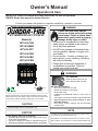
Owner’s Manual
Operation & Care
INSTALLER: Leave this manual with party responsible for use and operation.
OWNER: Retain this manual for future reference.
Contact your dealer with questions regarding installation, operation or service.
NOTICE: DO NOT DISCARD THIS MANUAL
WARNING
Please read this entire manual
before use of this pellet fuel-burning
room heater. Failure to follow these
instructions could result in property
damage, bodily injury, or death.
• Do not store or use gasoline or other flammable vapors and liquids in the vicinity of
this or any other appliance.
• Do NOT burn garbage or flammable fluids
such as gasoline, naphtha, or engine oil in
room heater.
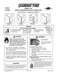
MT. VERNON PELLET STOVE E2
Model(s):
MTV-E2-CSB
MTV-E2-MBK
MTV-E2-PFT
MTV-E2-PDB
MTV-E2-PBK
MTV-E2-PMH
• Do not overfire - If heater or chimney connector glows, you are overfiring. Overfiring
will void your warranty.
• Comply with all minimum clearances to
combustibles as specified. Failure to
comply may cause house fire.
WARNING
HOT SURFACES!
Glass and other surfaces are hot
during operation AND cool down.
Tested and
Listed by
Portland
Oregon USA
O-T L
C
US
OMNI-Test Laboratories, Inc.
061-S-83-2
Please read this entire manual before installation and use of this
pellet fuel-burning room heater. Failure to follow these instructions
could result in property damage, bodily injury or even death
CAUTION
Hot glass will cause burns.
•
Do not touch glass until it is cooled
•
NEVER allow children to touch glass
•
Keep children away
•
CAREFULLY SUPERVISE children in same room as
fireplace.
•
Alert children and adults to hazards of high temperatures
•
High temperatures may ignite clothing or other
flammable materials.
•
Keep clothing, furniture, draperies and other flammable
materials away.
Tested and approved for wood pellets only
NOTE
CAUTION
To obtain a French translation of this manual, please contact
your dealer or visit www.quadrafire.com
Check building codes prior to installation.
• Installation MUST comply with local, regional, state and national codes and regulations.
• Consult local building, fire officials or authorities having jurisdiction about restrictions, installation inspection, and permits.
1
Pour obtenir une traduction française de ce manuel, s’il vous
plaît contacter votre revendeur ou visitez www.quadrafire.com
7080-132C
June 19, 2014
MT. VERNON E2
and Welcome to the Quadra-Fire Family!
A. Congratulations
tion of our stoves, inserts and fireplaces. And yet we are
old-fashioned when it comes to craftsmanship. Each unit
is meticulously fabricated and gold and nickel surfaces are
hand-finished for lasting beauty and enjoyment. Our pledge
to quality is completed as each model undergoes a quality
control inspection.
Hearth & Home Technologies welcomes you to our tradition
of excellence! In choosing a Quadra-Fire appliance, you
have our assurance of commitment to quality, durability, and
performance.
This commitment begins with our research of the market,
including ‘Voice of the Customer’ contacts, ensuring we
make products that will satisfy your needs. Our Research
and Development facility then employs the world’s most
advanced technology to achieve the optimum opera-
We wish you and your family many years of enjoyment in
the warmth and comfort of your hearth appliance. Thank
you for choosing Quadra-Fire.
NOTE: Clearances may only be reduced by means
approved by the regulatory authority having jurisdiction
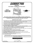
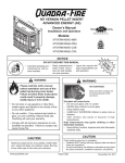
B. Sample of Serial Number / Safety Label
LOCATION: Back of Stove
HOT WHILE IN OPERATION
DO NOT TOUCH, KEEP
CAUTION:
CHILDREN, CLOTHING AND FURNITURE AWAY.
Test Lab &
Report No.
Tested and
Listed by
CONTACT MAY CAUSE SKIN BURNS. SEE NAMEPLATE
AND INSTRUCTIONS.
CHAUD LORS DE
L'OPÉRATION. NE PAS
TOUCHER. GARDEZ LES ENFANTS ET LES
VÊTEMENTS LOIN DE L'ESPACE DÉSIGNÉ DE
L'INSTALLATION. LE CONTACT PEUT CAUSER DES
BRÛLURES À LA PEAU. VOIR L'ÉTIQUETTE ET LES
INSTRUCTIONS.
ATTENTION:
Portland
Oregon USA
O-T L
US
C
OMNI-Test Laboratories, Inc.
Report:
061-S-83-2
SERIAL NO. / NUMÉRO DU
R
007058
Model
Name
Serial No.
Mt Vernon E2 Pellet Stove
Listed Solid Fuel Room Heater/Pellet Type. Also suitable for Mobile Home
Installation. This appliance has been tested and listed for use in Manufactured
Homes in accordance with OAR 814-23-9000 through 814-23-909.
Appareil de chauffage de combustible solide/de type de boulettes. Accepté dans
l'installation dans les maisons mobiles. Cet appareil a été testé et enregistré pour
l'usage dans les Maisons Mobiles en accord avec OAR 814-23-9000 jusqu'à
814-23-909.
PREVENT HOUSE FIRES / PRÉVENTION DES FEUX DE MAISON
Install and use only in accordance with manufacturer's installation and operating
instructions. Contact local building or fire officials about restrictions and inspection in
your area.
WARNING - FOR MOBILE HOMES: Do not install appliance in a sleeping room. An
outside combustion air inlet must be provided. The structural integrity of the mobile
home floor, ceiling and walls must be maintained. Refer to manufacturer's
instructions and local codes for precautions required for passing chimney through a
combustible wall or ceiling. Inspect and clean vent system frequently in accordance
with manufacturer's instructions. DO NOT CONNECT THIS UNIT TO A CHIMNEY
SERVING ANOTHER APPLIANCE. Use a 3" or 4" diameter type "L" or "PL" venting
system.
Installez et utilisez en accord avec les instructions d'installation et d'opération du
fabricant. Contactez le bureau de la construction ou le bureau des incendies au sujet
des restrictions et des inspections d'installation dans votre voisinage. Ne pas obstruez
l'espace en dessous de l'appareil.
AVIS - Pour Les Maisons Mobiles: Ne pas installer dans une chambre à coucher. Un
tuyau extérieur de combustion d'air doit être installé et ne doit pas être obstrué
lorsque l'appareil est en usage. La structure intégrale du plancher, du plafond et des
murs de la maison mobile doit être maintenue intacte. Référez vous aux instructions
du fabricant et des codes locaux pour les précautions requises pour passer une
cheminée à travers un mur ou un plafond combustibles, et les compensations
maximums. Inspectez et nettoyez la cheminée fréquemment. Ne pas connecter cet
appareil à une cheminée servant un autre appareil. Utilisez systèm de ventilation "L"
ou "PL" diamètre 76mm ou 102mm
Conforms to ASTM Std E1509-12. Certified to ULC S627-00. Room Heating Pellet
BurningType, (UM) 84-HUD FOR USE ONLY WITH PELLETIZED WOOD FUEL. Do
not use any other type of fuel.
Input Rating: 52,500 Btu's/hr. Electrical Rating:115 VAC, 60 Hz, Start 2.9 Amps, Run
2.45 Amps. Route power cord away from unit. Do not route cord under or in front of
appliance. Do not obstruct the space beneath the heater.
DANGER: Risk of electrical shock. Disconnect power supply before servicing.
Replace glass only with 5mm ceramic. To start, turn dial control to desired setting and
set thermostat above room temperature, the stove will light automatically. To
shutdown, turn dial control to OFF or set thermostat below room temperature. For
further instruction refer to owner's manual. Keep viewing doors tightly closed during
operation. Keep viewing and ash removal doors tightly closed during operation.
E
L
P
M
A
S
C
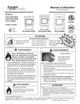
MINIMUM CLEARANCES TO COMBUSTIBLE MATERIALS
ESPACES LIBRES MINIMUM DES MATÉRIAUX
D
A
D
B
G
G
I
CANADA
G = 200 mm
H* = 200 mm
I = 450 mm
Owners Manual
A
B
C
D
Back Wall / Mur Arrière
Side Wall / Mur De Côté
“L” or “PL” Pipe to Back Wall / “L” ou “PL” Un Tuyau Mur Arrière
Side Wall / Mur De Côté
2 in [51 mm]
6 in [152 mm]
1 in [25 mm]
2 in [51 mm]
FLOOR PROTECTION / PROTECTION DU SOL
USA
G = 2 in
H* = 2 in
I = 6 in
H
Conforme à la norme ASTM E1509-12 Std. Certifié à la norme ULC S627-00. Room
Heating Pellet Burning Type, (UM) 84-HUD POUR USAGE AVEC LES BOULETTES
DE BOIS. N’utiliser aucun autre genre de combustible.
Puissance de Rendement: 52,500 Btu's/hr. Puissance Électrique: 115 VAC, 60 Hz,
Début 2.9 Amps, Courir 2.45 Amps, Éloignez le fil électrique de l'appareil. Ne pas faire
passer le fil électrique au dessus ou en dessous de l'appareil. Ne pas bloquer
l’espace au dessous de l’appareil.
DANGER: Il y a risque de décharge électrique. Déconnectez le fil électrique de la
prise de contact avant le service. Remplacez la vitre seulement avec une vitre
céramique de 5 mm disponible chez votre fournisseur. Pour commencer, tournez la
molette de réglage à la température désirée et réglez le thermostat au-dessus de la
température ambiante, le poêle s'allumera automatiquement. Pour éteindre, tournez la
molette de réglage sur OFF ou réglez le thermostat dessous de la température
ambiante. Pour des instructions supplémentaires, référez vous au manuel du
propriétaire. Gardez la porte d'ouverture et la porte des cendres fermées
hermétiquement durant l'opération.
Floor protector must be non-combustible
material, extending beneath heater and to
the front/sides/rear as indicated. Measure
front distance (I) from the surface of the
glass door.
Le poêle doit être placé sur une assise non
combustible s’étendant tout autour de lui,
comme les schémas l’indiquent. Mesurez la
distance du devant (I) de la surface de la
porte vitrée.
*Non-combustible floor protection must extend 2 inches
(51mm) beneath the flue pipe when installed with horizontal
venting or under the Top Vent Adapter with vertical installation.
RECOMMENDED IN USA; REQUIRED IN CANADA.
*Un protecteur incombustible de plancher doit s'étendre 2
inches (51mm) sous le conduit de cheminée pour une
installation de ventilation horizontale ou sous un adapteur de
ventilation de dessus pour une installation verticale.
RECOMMANDÉ AUX ÉTATS-UNIS; NÉCESSAIRE AU
CANADA.
Install Manual
Manufactured by:Fabriqué par
1445 North Highway, Colville, WA 99114
www.quadrafire.com
2013
2014
U.S. ENVIRONMENTAL PROTECTION AGENCY
Certified to comply with July 1990 particulate emission standards.
DO NOT REMOVE THIS LABEL / NE PAS ENLEVER L'ÉTIQUETTE
JUL
AUG
SEP
OCT
2015
JAN
FEB
MAR APR
MAY
JUN
Made in U.S.A. of US and imported parts.
Fabriqué aux États-Unis-d’Amérique par des pièces d’origine américaine et pièces importées.
2
7080-132C
NOV
Mfg. Date
DEC
7080-133
June 19, 2014
MT. VERNON E2
Safety Alert Key:
•
DANGER! Indicates a hazardous situation which, if not avoided will result in death or serious injury.
•
WARNING! Indicates a hazardous situation which, if not avoided could result in death or serious injury.
•
CAUTION! Indicates a hazardous situation which, if not avoided, could result in minor or moderate injury.
•
NOTICE: Indicates practices which may cause damage to the appliance or to property.
TABLE OF CONTENTS
A. Congratulations ........................................................2
B. Sample of Serial Number / Safety Label ..................2
C. Warranty Policy ........................................................4
D. Quick Start Guide.....................................................6
1 Listing and Code Approvals .............7
A.
B.
C.
D.
E.
Appliance Certification.............................................7
BTU & Efficiency Specifications ..............................7
Glass Specifications................................................7
Electrical Rating ......................................................7
Mobile Home Approved ........................................... 7
2 Operating Instructions ......................8
A. Fire Safety ................................................................8
B. Non-Combustible Materials .....................................8
C. Combustible Materials .............................................8
D. Fuel Material and Fuel Storage...............................8
E. Before Your First Fire ..............................................9
F. Filling the Hopper......................................................9
G. User Dial Control ....................................................9
H. Normal Startup Sequence........................................9
I. Firepot Purge ............................................................9
J. Shutdown ..................................................................9
K. Fire Characteristics .................................................10
L. Your Pellet Appliance’s General Operating Parts ....10
M. LED Color Coding Chart and Explanation ..............11
N. Restarting the Appliance ..........................................12
O. Clear Space ............................................................12
P. Trim Adjustment .......................................................12
Q. Remote Thermostat .................................................12
R. Bypassing the Remote System (Manual Mode).......13
S. Frequently Asked Questions ...................................14
June 19, 2014
3 Maintenance and Service ................15
A. Proper Shutdown Procedure ....................................15
B. Quick Reference Maintenance Chart ......................15
C. General Maintenance and Cleaning .......................16
D. Soot or Creosote Fire Awareness ............................19
E. High Ash Fuel Content Maintenance........................20
F. Baffle Removal .......................................................20
G. Glass Replacement ...............................................20
H. Convection Blower Replacement ...........................21
I . Combustion/Exhaust Blower Replacement .............22
4 Troubleshooting Guide....................23
5 Reference Materials .........................27
A. Component Functions .............................................27
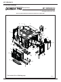
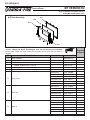
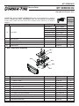
B. Exploded Drawings ..................................................28
C. Parts List ..................................................................29
7080-132C
3
MT. VERNON E2
C. Warranty Policy
Hearth & Home Technologies Inc.
LIMITED LIFETIME WARRANTY
Hearth & Home Technologies Inc., on behalf of its hearth brands (”HHT”), extends the following warranty for
HHT gas, wood, pellet, coal and electric hearth appliances that are purchased from an HHT authorized dealer.
WARRANTY COVERAGE:
HHT warrants to the original owner of the HHT appliance at the site of installation, and to any transferee taking ownership
of the appliance at the site of installation within two years following the date of original purchase, that the HHT appliance
will be free from defects in materials and workmanship at the time of manufacture. After installation, if covered components manufactured by HHT are found to be defective in materials or workmanship during the applicable warranty period,
HHT will, at its option, repair or replace the covered components. HHT, at its own discretion, may fully discharge all of its
obligations under such warranties by replacing the product itself or refunding the verified purchase price of the product
itself. The maximum amount recoverable under this warranty is limited to the purchase price of the product. This warranty
is subject to conditions, exclusions and limitations as described below.
WARRANTY PERIOD:
Warranty coverage begins on the date of original purchase. In the case of new home construction, warranty coverage
begins on the date of first occupancy of the dwelling or six months after the sale of the product by an independent,
authorized HHT dealer/ distributor, whichever occurs earlier. The warranty shall commence no later than 24 months
following the date of product shipment from HHT, regardless of the installation or occupancy date. The warranty period for
parts and labor for covered components is produced in the following table.
The term “Limited Lifetime” in the table below is defined as: 20 years from the beginning date of warranty coverage for
gas appliances, and 10 years from the beginning date of warranty coverage for wood, pellet, and coal appliances. These
time periods reflect the minimum expected useful lives of the designated components under normal operating conditions.
Warranty Period
Parts
Labor
1 Year
2 years
HHT Manufactured Appliances and Venting
Gas
X
X
Wood
X
X
X
3 years
Pellet
EPA
Wood
Coal
X
X
X
X
X
X
X
X
X
Components Covered
Electric Venting
X
X
All parts and material except as
covered by Conditions,
Exclusions, and Limitations
listed
Igniters, electronic components,
and glass
Factory-installed blowers
Molded refractory panels
Firepots and burnpots
X
5 years
1 year
7 years
3 years
10
years
1 year
X
Limited
3 years
Lifetime
X
X
X
X
X
90 Days
X
X
X
X
X
X
X
X
Castings and baffles
X
X
Manifold tubes,
HHT chimney and termination
Burners, logs and refractory
Firebox and heat exchanger
X
X
All replacement parts
beyond warranty period
See conditions, exclusions, and limitations on next page.
4
7080-132C
June 19, 2014
MT. VERNON E2
WARRANTY CONDITIONS:
!
"
"
WARRANTY EXCLUSIONS:
^
!
*
N
!!
!!!
!!
*
@
%
^!!"!
"!
!!!
Z
*!
!
N
^_`q
!
!
!
!
;_{q
;_|q
;_}q
!!!
!
!!
~
;_q
!+!
!
!"#
!
*
;_q
;_q
*
;_q*
;
~
_q
?#!
%
#*
'
*'
!
!
This warranty is void if:
#
!
!
$
#
!!
!
!!
"
%
!
!
LIMITATIONS OF LIABILITY:
'*
'
!
!*
!
!
!
!
!
!
+8
*
+!
;
!
<=<>$
<<=<?>@$KN<NOQRU!Z[<8?$<=>@<88U@@?<8$<@?<U@@?Q
8><\<N<@<?<N]@$?$\?QZ>R<NU@@?Q8RZ<N$N]@$?$\<
<=>@<88<NU@@?Q8><\<NO$K<
June 19, 2014
7080-132C
5
MT. VERNON E2
Set Up
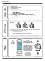
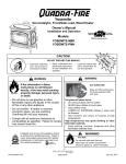
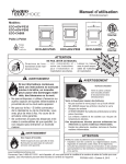
D. Quick Start Guide
1.
2.
3.
4.
5.
6.
Empty Firebox
Add pellets and close lid
Turn DIAL to OFF
Plug in the appliance
• Exhaust blower will run for about 45 Seconds (wait for it to stop
before priming)
• Green light will start flashing
Put batteries in the Touch Screen Remote Thermostat
Press the MODE button on the remote thermostat until ON appears
in the upperleft corner
• You should hear an audible tone from the appliance
1. After the exhaust blower has stopped; quickly turn the dial from OFF to HI
two times
EAT SET TING
EAT SET TING
EAT SET TING
H
LO
LO
HI
F
F
HI
OF
OF
HI
F
•
•
H
LO
OF
Prime
H
The LIGHT will turn solid green and pellets will feed. Wait for 2 minutes
If the LIGHT did not turn solid green:
- Turn dial back to OFF
- Unplug appliance, plug it back in and repeat
Priming is only needed for first fire or starting fire on empty hopper.
2. Choose Setting:
LO – HI*
Green LIGHT will begin flashing and stove
will start
7080-132C
LO
Dial
HI
1 0 +1
-3 -2 -
Run
6
S E T T I NG
+2 +3 +
Touch Screen
Remote Thermostat
*For first fire,
HHT recommends
running on HI for
first 30 minutes
HEAT
F
MODE/SET
ALARM
OF
It may take as long as 10
minutes to achieve a fire
in the firepot. Turning the
knob or thermostat to off
during this time will interrupt the startup process.
ON
-4
-pick “Temp”
Light
4
1. Choose Mode:
ON
or
THERM
Trim
Control Panel
June 19, 2014
MT. VERNON E2
1
Listing and Code Approvals
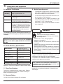
A. Appliance Certification
Model
Mt. Vernon Pellet Stove E2
Laboratory
OMNI Test Laboratories, Inc.
E. Mobile Home Approved
• This appliance is approved for mobile home installations when not installed in a sleeping room and when
an outside combustion air inlet is provided.
Report No.
061-S-83-2
Type
Solid Fuel Room Heater/Pellet Fuel
Burning Type
Standard
ASTM E1509-12, ULC S627-00 and
(UM) 84-HUD, Mobile Home Approved.
FCC
Complies with Part 15 of FCC Rules.
Operation is subject to the following two
conditions: (1) this device may not cause
harmful interference, and (2) this device
must accept any interference received,
including interference that may cause
undesired operation.
• The structural integrity of the mobile home floor, ceiling, and walls must be maintained.
• The appliance must be properly grounded to the
frame of the mobile home and use only Listed pellet
vent Class “L” or “PL” connector pipe.
• Outside Air Kit (OAK-3) must be installed in a mobile
home installation.
WARNING
The Quadra-Fire Mt. Vernon E2 Pellet Stove meets the U.S.
Environmental Protection Agency’s 1990 particulate emission
standards.
NOTICE: This installation must conform with local codes. In
the absence of local codes you must comply with the ASTM
E1059-12, ULC S627-00, (UM) 84-HUD and ULC/ORDC-1482.
B. BTU & Efficiency Specifications
EPA Certified:
1.7 grams per hour low
2.7 grams weighted average
Efficiency (LHV):
up to 87%
BTU Input:
18,000 to 52,500
BTU Output:
13,800 to 37,600
Heating Capacity:
up to 3,000 sq ft depending
on climate zone
Vent Size:
3” or 4” Type ‘L’ or ‘PL’
Fuel:
Wood Pellets
Fire Risk.
Hearth & Home Technologies disclaims any
responsibility for, and the warranty will be voided by,
the following actions:
• Installation and use of any damaged appliance.
• Modification of the appliance.
• Installation other than as instructed by Hearth & Home
Technologies.
• Installation and/or use of any component part not approved by
Hearth & Home Technologies.
• Operating appliance without fully assembling all components.
• Operating appliance without legs attached (if supplied with unit).
• Do NOT Overfire - If appliance or chimney connector glows,
you are overfiring.
Any such action that may cause a fire hazard.
Improper installation, adjustment, alteration, service or
maintenance can cause injury or property damage.
For assistance or additional information, consult a qualified
installer, service agency or your dealer.
426 lbs
Shipping Weight:
*BTU will vary, depending on the type of fuel you use in your
appliance. Consult your Quadra-Fire dealer for best results.
C. Glass Specifications
This stove is equipped with 5mm ceramic glass. Replace
glass only with 5mm ceramic glass. Please contact your
dealer for replacement glass.
NOTE: Hearth & Home Technologies, manufacturer of
this appliance, reserves the right to alter its products, their
specifications and/or price without notice.
Quadra-Fire is a registered trademark of Hearth & Home
Technologies.
D. Electrical Rating
115 VAC, 60 Hz, Start 2.9 Amps, Run 2.45 Amps
June 19, 2014
7080-132C
7
MT. VERNON E2
2
User Guide
Operating Instructions
Fuel Material
WARNING
• Made from sawdust or wood by-products
• Depending on the source material it may have a high or
low ash content.
Fire Risk.
•
Do not operate appliance before reading and
understanding operating instructions.
•
Failure to operate appliance properly may cause
a house fire.
A. Fire Safety
To provide reasonable fire safety, the following should be
given serious consideration:
Higher Ash Content Material
• Hardwoods with a high mineral content
• Fuel that contains bark
• Standard grade pellets or high ash pellets
Lower Ash Content Material
• Install at least one smoke detector on each floor of your
home.
•
•
•
• Install at least one carbon monoxide detector on each floor
of your home.
Clinkers
• Locate smoke detector away from the heating appliance
and close to the sleeping areas.
Minerals and other non-combustible materials such as sand
will turn into a hard, glass-like substance called a clinker when
heated in the firepot.
• Follow the smoke detector manufacturer’s placement and
installation instructions and maintain regularly.
Trees from different areas will vary in mineral content. That
is why some fuels produce more clinkers than others.
• Follow the carbon monoxide manufacturer’s placement and
installation instructions and maintain regularly.
Moisture
• Conveniently locate a Class A fire extinguisher to contend
with small fires.
Always burn dry fuel. Burning fuel with high moisture content
takes heat from the fuel and tends to cool the appliance,
robbing heat from your home. Damp pellet fuel can clog the
feed system.
•
In the event of a hopper fire:
• Evacuate the house immediately.
• Notify fire department.
Size
B. Non-Combustible Materials
Material which will not ignite and burn, composed of any
combination of the following:
- Steel
- Plaster
- Glass
- Tile
- Brick
- Iron
- Slate
- Concrete
Materials reported as passing ASTM E 136, Standard
Test Method for Behavior of Metals, in a Vertical Tube
Furnace of 750° C.
C. Combustible Materials
Material made of/or surfaced with any of the following
materials:
- Compressed Paper
- Wood
- Plywood/OSB
- Sheet Rock (drywall)
- Plastic
- Plant Fibers
Any material that can ignite and burn: flame proofed or not,
plastered or un-plastered.
D. Fuel Material and Fuel Storage
Pellet fuel quality can greatly fluctuate. We recommend that
you buy fuel in multi-ton lots whenever possible. However,
we do recommend trying various brands before purchasing
multi-ton lots to ensure your satisfaction.
8
Most softwoods
Fuels with low mineral content
Most premium grade pellets
• Pellets are either 1/4 inch or 5/16 inch (6-8mm) in diameter
• Length should be no more that 1-1/2 inches (38mm)
• Pellet lengths can vary from lot to lot from the same
manufacturer
• Due to length variations, the feed rate may need adjusting
occasionally
Performance
• Higher ash content requires the firepot and the ash drawer
to be emptied more frequently
• Hardwoods require more air to burn properly
• Premium wood pellets produce the highest heat output
• Burning pellets longer than 1-1/2 inches (38mm) can cause
an inconsistent fuel feed rate and/or missed ignitions or
feed jams.
Storage
• Wood pellets should be left in their original sealed bag until
using to prevent moisture absorption
• Do not store any pellet fuel within the clearance requirements
or in an area that would hinder routine cleaning and
maintenance
7080-132C
June 19, 2014
MT. VERNON E2
E. Before Your First Fire
1. First, make sure your appliance has been properly
installed and that all safety requirements have been met.
Pay particular attention to the fire protection and venting.
2. Double check that the firebox is empty and the firepot
floor is fully closed.
This startup cycle continues until the unit senses ignition by
a rise in the exhaust temperature or the unit times out. Following the ignition cycle the unit continues to feed pellets to
build up the fire.
3. Close and latch the door.
After warming up, the convection blower will begin to blow
warm air into the room. As the appliance increases heat
the blower will increase its output.
F. Filling the Hopper
I. Firepot Purge
Purpose: To help remove debris from the firepot and help
the unit burn as efficient as possible.
Open the hopper lid by lifting the handle. Fill the hopper
with fuel. Close the hopper lid. The unit will not feed with
the hopper lid open and the fire will go out.
The frequency of the purge cycle is once every 50 minutes
while the unit is burning. During the firepot purge, the feed
is reduced to the lowest setting and the exhaust blower
ramps up to a very high setting. The purge cycle lasts 99
seconds.
NOTE: FOR USE WITH ONLY WOOD PELLET FUEL
G. User Dial Control
The appliance has one dial control located on the side of
the unit (behind a drop door) used for changing the heat
setting and restarting the appliance. There are five heat
settings on this dial ranging to include: LOW, MED-LOW,
MED, MED-HIGH, and HIGH. Figure 9.1
The purge cycle does not replace daily cleaning.
J. Shutdown
Turn the dial control to the desired heat setting and turn the
appliance ON and OFF using the remote thermostat.
HEAT
To shut the appliance down, turn the dial control to OFF
or turn the thermostat to OFF. During the shutdown process, the light will flash green rapidly just like the ignition
sequence.
Unlike the firepot purge, during shutdown existing fuel in
the firepot will continue to burn without the feed motor running; but, the exhaust and convection blowers will remain
on until the exhaust has cooled.
S E T T I NG
LO
OF
F
NOTE: If maintenance or daily cleaning is going to be
conducted immediately following a shutdown, please use
caution as components especially those inside the firebox
may still be hot.
HI
Due to safety precautions:
• If the dial control is turned to OFF and back on (even
if by mistake) the unit will go through the shutdown
sequence before restarting.
• Additionally, if the remote thermostat is set to “OFF” or
“THERMOFF” during operation the appliance will go
through a shutdown sequence before restarting.
Figure 9.1
H. Normal Startup Sequence
The unit will go into the ignition sequence followed by a
start up sequence (the green LED will flash rapidly).
The ignition sequence involves the exhaust blower and
igniter turning on, and the feed motor running in two stages.
The first stage involves the feed motor running continuously
for about a minute to preload pellets into the firepot. In the
second stage, the feed motor will begin cycling on and off.
When the pellets are warming - on the verge of igniting - it
is not uncommon for the firebox to fill with smoke.
Once ignition happens, the smoke should quickly disappear. During this stage, as well as any part during the burn
process, the front door should not be opened.
June 19, 2014
CAUTION
HOT WHILE IN OPERATION. KEEP CHILDREN, CLOTHING
AND FURNITURE AWAY. CONTACT MAY CAUSE SKIN
BURNS.
7080-132C
9
MT. VERNON E2
K. Fire Characteristics
The overall height of the flame will vary throughout the burn
for a couple of reasons:
1) The flame will vary based on type of fuel or batch of
fuel.
2) The unit adjusts the burn rate according to the dial setting – the further the dial is rotated clockwise the higher
the flame and consequently, heat output.
3) General maintenance and cleaning. Infrequent or poor
general maintenance will result in poorer performance.
Indicators for additional maintenance activities include:
lazy flame
black-sooted glass
pellets not igniting
excess pellets falling to the side of the firepot.
4) See trim adjustment section for additional information.
CAUTION
Odors and vapors released during initial operation.
• Curing of high temperature paint.
• Open windows for air circulation.
Odors may be irritating to sensitive individuals.
WARNING
HOT SURFACES!
Glass and other surfaces are hot during
operation AND cool down.
Hot glass will cause burns.
• DO NOT touch glass until it is cooled.
• NEVER allow children to touch glass.
• Keep children away.
• CAREFULLY SUPERVISE children in same room as
appliance.
• Alert children and adults to hazards of high temperatures.
High temperatures may ignite clothing or other
flammable materials.
• Keep clothing, furniture, draperies and other flammable
materials away.
NOTICE: If you expect children to come into contact with
this appliance, we recommend a barrier such as a decorative screen. See your retailer for suggestions.
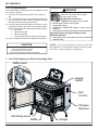
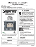
L. Your Pellet Appliance’s General Operating Parts
Baffle Latch
Hopper
Switch
Dial
Control
Wireless
Reciever
Ash Dump Lever
Baffle
10
Firepot
7080-132C
June 19, 2014
MT. VERNON E2
M. LED Color Coding Chart and Explanation
The number of flashes between pauses is per one second unless otherwise indicated.
LED
Color
Green
Green
No. of Flashes
between pauses
Steady ON while
priming feed tube
(max time
2 minutes)
1x every 2
seconds
Description
Notes
Feed Motor is running
continuously.
(priming the feed tube)
When priming the feed system and filling the firepot, DO
NOT OVERFILL FIREPOT FOR IGNITION. The unit will
automatically go into start up following the prime function.
Unit is on standby
To start appliance, follow start up sequence.
Green
Blinks Continuously
Green
Green
Green
Green
Green
1X
2X
3X
4X
5X
Appliance is in the start
up/ignition sequence or in
shutdown.
Stage 1: Low heat
Stage 2: Med-Low heat
Stage 3: Med heat
Stage 4: Med-Hi heat
Stage 5: Hi heat
Red
1X
Empty Hopper Alarm
Red
2X
Exhaust Probe Alarm
Red
4X
Missed Ignition
Red
6X
Encoder Alarm
Red
8X
Exhaust Over
Temperature Alarm
During shut down, the blowers will shut off when the
exhaust temperature has cooled.
BTU Range: 1,8653 - 19,694
Average: 19,054
BTU Range: 22,102 - 23,506
Average: 22,735
BTU Range: 30,778 - 32,680
Average: 31,603
BTU Range: 38,576 - 42,914
Average: 40,665
BTU Range: 49,830 - 52,460
Average: 51,528
This alarm is caused by the fire going out from lack of fuel.
Reset by turning to “OFF” then turn dial to desired setting.
Failed component error. See troubleshooting section for
more information.
There are a total of 2 tries per ignition sequence. If after
2 tries there is no rise in exhaust temperature this error
will occur. See the troubleshooting section for additional
information.
Failed Component Error: Exhaust Speed Sensor. See
troubleshooting guide for more information
See troubleshooting guide for more information.
WARNING
Fire Risk
Do NOT operate appliance:
• With appliance door open.
• Firepot floor open.
Do NOT store fuel:
• Closer than required clearances to combustibles to appliance
• Within space required for loading or ash removal.
June 19, 2014
7080-132C
11
MT. VERNON E2
N. Restarting the Appliance
Restart Process
1. When the unit has run out of fuel and the “empty
hopper” error code illuminates, add pellet fuel to the
hopper.
2. Dump the ashes and clinkers built up in the firepot by
pulling the ash dump removal handle out several times.
Make sure clinkers have dropped into the ash pan then
return the handle to fully closed position.
3. Turn the dial control to OFF and then up to high 2X to
prime.
4. After seeing pellets drop then turn to desired setting to
reset the appliance control system. The appliance will
then being its startup sequence.
Restarting After a Power Failure
1. For an electrical disruption the appliance will start on
its own without need for priming - providing the control
system is asking for heat.
2. The appliance will always go through a normal shutdown sequence before restarting.
Remote Power Requirements
• The remote receiver power is maintained through appliance power.
• The remote thermostat uses four AAA batteries.
O. Clear Space
NOTICE: Clearances may only be reduced by means
approved by the regulatory authority having jurisdiction.
Mantel: Avoid placing candles and other heat-sensitive objects on mantel or hearth. Heat may damage these objects.
P. Trim Adjustment
The small dial located below the main dial control is used
to adjust the amount of combustion air for the fire. You may
need to adjust the combustion air to the fire for:
• Elevation
• Venting/Installation Configurations
• Fuel Quality
If your fire is too large, lazy, or producing black soot, you
need MORE air. To increase the amount of combustion
air, rotate the dial clockwise one level at a time and allow
15 minutes for stabilization prior to making another adjustment. If the fire continues to appear too rich turn the trim
dial setting counterclockwise to the negative numbers to
decrease fuel flow. Figure 12.1
If the fire is too small or occasionally goes out when there
are pellets in the hopper, the unit may have too much air.
To decrease the amount of combustion air, rotate the trim
dial towards zero one level at a time and allow 15 minutes
for stabilization prior to making another adjustment.
12
More Air & Less Fuel
More Air
Figure 12.1
Q. Remote Thermostat
Learning Remote Thermostat to Receiver
1. With receiver and remote thermostat powered, set the
receiver to “REMOTE” and remote thermostat to “ON”.
2. Push receiver “LEARN” button momentarily - an audible tone should emit from the receiver.
3. Push the remote thermostat “MODE” button until “OFF”
shows on the screen - an audible sound should emit
from the receiver.
4. To check whether the receiver is “learned” push
“MODE” on the remote thermostat several times - an
audible sound should be heard from the receiver.
5. If no sound is heard repeat the process.
Remote Thermostat: Instructions
1. The remote thermostat activates an internal “on-off”
switch in the receiver (located in the appliance).
2. If the remote thermostat setting is higher than its local
surrounding temperature it will signal the receiver to
turn ON; if the user setting is equal to- or less than the
local surrounding temperature then the remote thermostat will signal the receiver to turn OFF.
Remote Thermostat: Setting Clock
1. Push “TIMER” on the screen of for more than two seconds. The hour digit(s) should begin to flash.
2. Press the UP or DOWN buttons until the desired hour
is displayed (notice the AM - PM).
3. After setting the desired hour, press and release
“TIMER” again and the minute digits will begin flashing.
4. Press the UP or DOWN buttons until the desired minutes are displayed.
5. Press “MODE” or “TIMER” buttons again for more than
two seconds then release.
6. The minute digits will stop flashing, the clock has been
successfully set.
Remote Thermostat: Countdown Timer Function
1. Change the mode to “ON” (or “THERMON” with the set
point higher than the room temperature), push “TIMER”
on the screen.
2. 0:15 should appear on the screen.
3. Pressing the up and down arrows will allow for increase
and decrease of the timer (15-minute increments up to
1-hour; 30 –minute increments after 1-hour).
4. When the timer expires the remote should send an
“OFF” signal to the appliance.
7080-132C
June 19, 2014
MT. VERNON E2
Remote Thermostat: Fahrenheit / Celsius
1. Temperatures will show either °F or °C displayed on the
screen.
2. Press both “UP” and “DOWN” arrow keys simultaneously. The display should change from Fahrenheit to
Celsius or vice-versa.
Remote Thermostat: Swing
1. The swing temperature will allow over-target of the
set point temperatures set while in “THERMO” mode.
Example, if the set point temperature is 70°F and swing
is ±2° the appliance will not go into a shutdown until it
reaches 72°F. Likewise, the appliance will not startup
unless it is below 68°F.
2. To change the temperature “SWING” setting (1°-3°),
press the TIMER and DOWN buttons simultaneously to
display the current “SWING” setting in the SET TEMP
frame.
3. The letter “S” will display in the ROOM TEMP frame on
the screen.
4. Press the UP or DOWN button to change the temperature differential (from 1º to 3º).
5. To store the “swing number press the MODE/SET
button or allow 15 seconds to lapse, and the new
“swing number’ will be programmed.
6. To verify that the swing is properly set, and with the
appliance dial control set to “OFF” & remote thermostat
set to “THERMO”, raise and lower the temperature
above and below the room temperature to identify its
response. This should change from THERMON to
OFFTHERMO.
Remote Thermostat: Child Lockout feature
1. To activate the “LOCK-OUT” feature, press and hold
the UP button and touch the word TIMER on the screen
of the transmitter together, for 5 seconds. The lock
icon will appear on the screen.
2. To disengage the “LOCK-OUT”, press and hold the
UP button and touch the word TIMER on the screen
together for 5 seconds or more, and the lock icon will
disappear from the screen. The transmitter will return to
its normal operating condition.
Note: If the appliance is already operating in the ON or
THERMO MODES, engaging the “LOCK-OUT” will not
cancel the operating MODE. Engaging the “LOCK-OUT”
prevents only the manual operation of the TRANSMITTER.
If in the auto modes, the THERMO operation will continue
to operate normally. To completely “LOCK-OUT” the operation of the TRANSMITTER’S operating signals; the transmitter’s MODE must be set to OFF.
Remote Thermostat: Signal
1. The remote thermostat sends a signal to the receiver
every 15 minutes verifying the transmitter is still in
range.
2. If the remote thermostat falls out of signal range for
over 2 hours or has no battery power the receiver will
emit a communication Safety Error Code consisting
June 19, 2014
of a series of rapid “beeps” for a period of 10 seconds
and the appliance will shut down. After 10 seconds of
rapid beeping, the receiver will continue to emit a single
“beep” every 4 seconds until the remote thermostat
MODE button is pressed, resetting the receiver.
Note: Unless damaged or remote component is replaced
the receiver will maintain its communication link to its transmitter for many years.
Remote Trouble Shooting
1. Make sure the remote thermostat’s batteries are properly installed.
2. Check to make sure the thermostat is communicating
with the receiver (an audible sound from the receiver
should emit when changing from “OFF” to “ON”).
3. If the receiver does not beep when changing from OFF
to ON, you will need to “LEARN” the receiver to the
remote thermostat. (See Learning the remote thermostat to receiver section).
4. Make sure the remote thermostat is within the 15 to
20-foot range of the receiver.
R. Bypassing the Remote System (Manual
Mode)
1. If the remote thermostat is lost, broken, or loses its
power the appliance can be operated in manual mode.
2. Locate the three-way switch on the receiver. Figure
14.1
3. Placing the receiver three-way switch to “ON” will
bypass the remote thermostat function, rendering the
appliance dial control as its exclusive control.
4. The appliance will not run when the switch is set to
“OFF”.
Location of the Remote Receiver:
The receiver face can be seen on the lower RH side toward
the back [without removing the side panel].
Note: Placing the receiver three-way switch in the
“REMOTE”, or center-most position empowers the remote
system.
Figure 14.1
7080-132C
13
MT. VERNON E2
S. Frequently Asked Questions
What causes my glass to become dirty?
If the glass has white ash build up it is normal and the
glass should be cleaned. If it is a black soot build up airflow
through the unit may be restricted. The most often cause is
overdue maintenance and cleaning. See “Maintaining and
Servicing Appliance” and/or make adjustments to the trim
control.
How can I get more heat out of the appliance?
The most often cause of diminished heat output is overdue
maintenance and cleaning. See “Maintaining and Servicing
Appliance”.
What should I do if I smell smoke or there is ash/soot
coming from the appliance?
While there will always be some smoke smell from wood
burning appliances (including pellet) you should investigate
all venting to make sure it is sealed properly. Most venting
requires silicone to seal the seams.
In addition most homes are built very tight today and with
exhaust systems can create negative pressure in the
home. See “Negative Pressure” under “Getting Started” in
the owner’s manual if you have checked the venting but
still have smoke coming from the appliance. For ash or
soot check the above and the exhaust blower housing and
seals.
Why is there a black residue building up on the outside
of my home?
Wind can cause this to happen. If the appliance is operating correctly very little soot should ever exit the termination cap. Check to be sure the venting is installed per the
owner’s manual and local codes.
Do I need an outside air kit?
Outside air is required for mobile home installs and in some
jurisdictions. Refer to “Listing & Code Approvals”,“ Mobile
Home Installation” and “ Appliance Set-up”. Also refer to
local building codes.
I am seeing sparks coming out of my pipe (termination
cap) outside is this safe?
This is normal. As long as clearances to combustibles were
followed this is safe.
I have no power to anything. Does this unit have a circuit breaker or fuse or a reset button?
This unit has one fuse on the control board and a resettable
snap disc mounted to the feed tube. If the appliance overheats then the snap disc can be reset; if the fuse is blown
the control board must be replaced.
Can I burn corn in my unit?
No. Corn is not an approved fuel for this model.
Why would my appliance run fine last winter but not
start this fall?
It is possible that the stove was not properly prepared for
the Non-burn season (see troubleshooting section).
Is there a place to lubricate the blowers to quiet them
down?
No. The most often cause of noisy blowers is from the
impellers becoming dirty over time. See maintenance and
service section for maintaining and servicing.
Where is the serial # located on my unit?
Freestanding - the serial number is located on the back of
the stove.
No pellets are dropping in my firepot.
See troubleshooting guide.
What is the metal object with the bend in it that came
inside the plastic bag?
It is a clean-out tool used to help clean the firepot and
remove any jams in the rare event they occur in the feed
tube.
Contact your dealer for additional information regarding operation and troubleshooting.
Visit www.quadrafire.com to locate a dealer.
14
7080-132C
June 19, 2014
MT. VERNON E2
3
Maintenance and Service
When properly maintained, your appliance will give you
many years of trouble-free service. Contact your dealer to
answer questions regarding proper operation, troubleshooting and service for your appliance. Visit www.quadrafire.
com to locate a dealer. We recommend annual service by a
qualified dealer.
CAUTION
Shock and Smoke Hazard
• Smoke spillage into room can occur if appliance
is not cool before unplugging.
• Risk of shock if appliance not unplugged before
servicing appliance.
A. Proper Shutdown Procedure
Turn dial control to OFF, let appliance completely cool and
exhaust blower must be off. After cooling unplug appliance
before servicing.
Follow the detailed instructions found in this
section for each step listed as referenced in
the chart below.
B. Quick Reference Maintenance Chart
Cleaning or Inspection
Frequency
Daily Weekly Monthly
Yearly
Firepot
Every 2 bags of fuel
OR
Ash Removal from Firebox
About 5 bags of fuel depending on ash build-up
OR
X
Glass
When clear view of firepot
becomes obscure
OR
X
Hopper
Every ton of fuel (50 bags)
OR
X
Exhaust Path, Drop Tube and Behind
Baffles
Every ton of fuel (50 bags) or
more frequently
OR
X
Door Handle & Gasket Inspection
Prior to heating season
OR
X
Blower, Convection
Every ton of fuel or more frequently depending on performance
OR
X
Every ton of fuel or more frequently depending on performance
OR
X
Firebox - Prepare for Non-Burn Season
At end of heating season
OR
X
Venting System
Every 3 tons of fuel or more
frequently depending on performance
OR
X
Blower, Exhaust
X
NOTICE: These are recommendations. Clean more frequently if you encounter heavy build-up of
ash at the recommended interval or you see soot coming from the vent. Not properly
cleaning your appliance on a regular basis will void your warranty.
June 19, 2014
7080-132C
15
MT. VERNON E2
2. Cleaning Ash Pan
• Frequency: Weekly or every 3-5 bags
C. General Maintenance and Cleaning
•
1. Cleaning Firepot using Lever
•
•
Frequency: Daily
By: Homeowner
a. Be sure the appliance is allowed to cool.
b. Open cast face of appliance
c. Pull firepot floor cleaning lever two times until the ash falls
into the ashpan below. Figure 16.2
d. It may be necessary to use your firepot clean-out tool to
chip away material that has built up on the sides of the
firepot and to push out any clinkers. Figure 16.1
e. Larger clinkers may have to be removed from the top of
the firepot.
f. If the clinker adheres to the sides of the firepot, you
will need to manually clean the firepot. The firepot floor
plate must be fully closed when finished.
By: Homeowner
a. Locate the ash pan underneath the firepot.
b. Slide the ash pan straight out.
c. Empty into a non-combustible container and re-install
ash pan.
d. When replacing ash pan push it back until it catches on
the 2 side latches.
Clinkers filling the ash pan will have to be cleaned out more
often than ash.
Ash Disposal:
Ashes should be placed in a steel container with a tightfitting lid. The container of ashes should be moved outdoors
immediately and placed on a non-combustible floor or on
the ground, well away from combustible materials, pending
final disposal.
If the ashes are disposed of by burial in soil or otherwise locally
dispersed, they should be retained in the closed container until
all cinders have thoroughly cooled. Other waste shall not be
placed in this container.
3. Ash Removal from Firebox
Clinker
•
Figure 16.1 - Firepot with large clinker
•
Frequency: Weekly or more frequently depending on
ash build-up
By: Homeowner
a. Be sure the appliance is allowed to cool.
b. There must not be any hot ashes in the firebox during
cleaning.
c. Frequent cleaning of the ash in the firebox with a
vacuum cleaner will help slow down the build-up of ash
in the exhaust blower and vent system.
WARNING
RISK OF FIRE
Keep combustible materials, gasoline and other flammable vapors and liquids clear of appliance.
• Do NOT store flammable materials in the appliance’s vicinity.
Figure 16.2
• Do NOT use gasoline, lantern fuel, kerosene, charcoal lighter
fluid or similar liquids to start or “freshen up” a fire in this heater.
Keep all such liquids well away from the heater while it
is in use as combustible materials may ignite.
4. Cleaning Heat Exchanger & Drop Tube
•
•
Frequency: Monthly or every ton of fuel (50 bags).
By: Homeowner
NOTE: Heavy duty vacuum cleaners may be obtained, specifically designed for solid fuel appliance cleaning.
16
7080-132C
June 19, 2014
MT. VERNON E2
Cleaning Heat Exchanger & Drop Tube (cont.)
Tools Needed: A Shop Vacuum and generic micro cleaning
kit; flat head screwdriver; bottle brush, ½” ID hose.
a. It is necessary to remove the baffle to gain access to the
heat exchanger (figure 17.2). Follow instructions for baffle
removal on page 20, figure 20.2.
b. Vacuum the ash from the heat exchanger with an
upholstery brush to remove the majority of the ash. Be
sure to vacuum the back of the baffle also. Inspect the
drop tube and remove any residue build-up in the drop
tube. Figure 17.3
c. Assemble the crevice tool from the micro cleaning kit to
attach to a Shop Vac. Figure 17.4
d. Use the crevice tool to finish cleaning the heat exchanger
fins. It is critical that the 2 exhaust exits at the back of the
firebox floor (left and right) be thoroughly cleaned. Figure
17.2 There are several ways this can be done:
Shop Vacuum and Micro Cleaning Kit examples - items
that can be purchased at local hardware stores.
* Can be purchased at your local hardware store.
1. Use the crevice tool.
2. Attach a hose 1/2 inch (12.7mm) inside diameter and
approximately 2 feet (607mm) in length to your vacuum
hose.
3. Use a bottle brush and push the ash down to the
bottom. Remove the combustion (exhaust) blower and
then vacuum out the ash.
Figure 17.2 - Example of a dirty heat exchanger
WARNING
Hopper Fire Risk!
For trouble free use of your pellet appliance you
must perform cleaning as called for in these instructions. Not doing so will result in:
• Poor operating performance
• Smoke spillage into the home
• Overheating of components
Not properly cleaning your appliance on a regular basis
will void your warranty.
Figure 17.3
Figure 17.4
Exhaust exits must be thoroughly cleaned.
Each exit is approximately 4 inches wide, 1
inch across, and 3 inches deep
Figure 17.1
June 19, 2014
7080-132C
17
MT. VERNON E2
5. Ash Removal System Inspection & Cleaning
6. Cleaning the Hopper
•
•
•
•
Frequency: Monthly or after burning 50 bags
By: Homeowner
a. Be sure the appliance is allowed to cool.
b. Open the front cast door and cycle the ash removal handle
- these should be inspected for functionality
c. Inspect for any degradation or deformation.
As the springs heat up and cool down they can lose
tension
If there is a gap showing above the firepot bottom,
approximately 1/16 inch (1.59mm) or more, it means
the springs have lost their tension
Lost tension cannot keep the floor in the proper
position causing ignition problems and fuel falling
into the ash pan. If noted, call your dealer to replace
the springs.
Frequency: See chart on page 15
By: Homeowner
a. Be sure the appliance is allowed to cool.
b. After burning approximately 1 ton of fuel you will need to
clean the hopper to prevent sawdust and/or fines build-up.
c. A combination of sawdust/fines and pellets on the auger
reduces the amount of fuel supply to the firepot.
d. This can result in nuisance shut downs and mis-starts
•.
Empty the hopper of any remaining pellets.
•.
Vacuum the hopper and feed tube.
7. Cleaning the Glass
• Frequency: See chart on page 15
• By: Homeowner
a. Be sure the appliance is allowed to cool.
b. Clean glass with a non-abrasive commercially available
cleaner. Wipe down with dry towel.
CAUTION
Handle glass assembly with care.
When cleaning glass door:
• Avoid striking, scratching or slamming
glass.
• Do NOT clean glass when hot.
Ash Dump Lever
• Do NOT use abrasive cleaners.
Figure 18.1
• Use a hard water deposit glass cleaner on white film.
Refer to maintenance instructions.
WARNING
Risk of fire!
WARNING
Do NOT store fuel:
• Closer than required clearances to combustibles
to appliance.
• Within space required for loading or ash removal
Handle glass doors with care.
• Inspect the gasket to ensure it is
undamaged.
• Do NOT strike, slam or scratch glass.
• Do NOT operate appliance with glass door
removed, cracked, broken or scratched.
8. Door Latch & Gasket Inspection
•
•
Frequency: See chart on page 15
By: Homeowner
The door latch is non-adjustable but the gasketing between
the glass and firebox should be inspected periodically to make
sure there is a good seal. If the gasket is frayed or damaged,
replace with a new one.
18
7080-132C
June 19, 2014
MT. VERNON E2
9. Cleaning Exhaust System (Requires No
Lubrication)
•
•
12. Soot and Fly-ash: Formation & Need for Removal
in Exhaust Venting System.
• Frequency: See chart on page 15
• By: Qualified Service Technician and/or Homeowner
Frequency: See chart on page 15
By: Homeowner
a. Be sure the appliance is allowed to cool.
b. Remove blower per replacement section instructions.
c. Use a soft brush and vacuum to clean the impeller.
d. Vacuum out exhaust path and housing. Figure 19.1
e. Replace fan (make sure elect connections are fully
assembled)
a. The products of combustion will contain small particles
of fly-ash. The fly-ash will collect in the exhaust venting
system and restrict the flow of the flue gases. Incomplete combustion, such as occurs during startup, shutdown, or incorrect operation of the room heater will lead
to some soot formation which will collect in the exhaust
venting system.
Note: Ash will build up more quickly in the horizontal
venting sections.
13. Preparing Firebox for Non-Burn Season
• Frequency: See chart on page 15
• By: Homeowner
a. The appliance must be in complete shutdown and
allow the appliance to completely cool down.
b. Remove all ash from firebox and vacuum thoroughly.
c. To minimize corrosion, paint all exposed steel, including
cast-iron. Use the Touch-Up paint supplied with the
appliance or purchase paint from your local dealer. You
must use a high-temperature paint made specifically for
heating appliances.
d. Cleaning the flue at the end of the burn season will
prevent corrosives to build-up and damage the flue.
D. Soot or Creosote Fire Awareness
The chimney should be inspected periodically during the
heating season to determine if a creosote build-up has
occurred. If a significant layer of creosote has accumulated
(1/8 inch [3mm] or more) it should be removed to reduce
the risk of chimney fire.
Figure 19.1
10. Cleaning Convection Blower Requires No
Lubrication
• Frequency: See chart on page 15
• By: Homeowner
a. Be sure the appliance is allowed to cool.
b. Remove blower per replacement section instructions.
c.
Use a soft brush and vacuum to clean the blower
wheel.
11. Cleaning the Top Vent Adapter (if installed)
•
•
a.
b.
c.
Check daily for creosote build-up until experience shows
how often you need to clean to be safe. Be aware that the
hotter the fire the less creosote is deposited, and weekly
cleaning may be necessary in the mild weather even though
monthly cleaning may be enough in the coldest months.
Contact your local municipal or provincial fire authority for
information on how to handle a chimney fire.
In the event of a soot or creosote fire, close the firebox
door, exit the building immediately and contact the proper
fire authorities.
Frequency: As needed
By: Homeowner
Be sure the appliance is allowed to cool.
Open the clean out cover.
Sweep out any ash build-up.
DO NOT under any circumstances re-enter the building.
NOTE
•
This unit is required to be cleaned frequently
because soot creosote and ash may accumulate.
June 19, 2014
7080-132C
19
MT. VERNON E2
E. High Ash Fuel Content Maintenance
•
•
Frequency: Daily
By: Homeowner
Baffle
If the ash build-up exceeds the half way point in the firepot or
if clinkers are adhering to the sides of the firepot, the firepot
floor is not being cycled enough.
WARNING
Risk of Fire and Smoke!
• High ash fuels or lack of maintenance can cause
firepot to overfill. Follow proper shutdown procedure if ash buildup exceeds half way point in firepot.
Latches
Insert flat head screw driver into “V”
section and push down and the bottom
of the latch will fall forward off of post
• Failure to do so could result in smoking, sooting and possible hopper fires.
Locating ears - 1 on
each side. Fit behind
bottom edge.
Figure 20.2
G. Glass Replacement
1. Swing open the face and remove the door from the
appliance by lifting the door off of the hinge pins and lay
on a flat surface face down.
Pellets Back-Up
in Feed Tube
2. Using a Phillips head screw driver, remove 4 screws, 2
on the top and 2 on the bottom. Remove metal bracket
and then remove the glass. Figure 20.3
Firepot Overfills
3. Replace with new glass with gasket.
4. Re-attach metal bracket with 4 screws.
5. Re-install door over hinge pins and close face.
Ash Build-Up in Firebox
Figure 20.1
WARNING
F. Baffle Removal
• Glass is 5mm thick high temperature heat-resistant ceramic glass.
1. The appliance must be in complete shutdown, completely cool and the exhaust blower off.
2. Open door.
3. The baffle is located at the top inside of firebox.
4. Remove baffle by placing a flat head screw driver into
the slot of the latches located in the upper corners and
rotate down. The bottom of the latch will fall forward off
of the post. Lift the baffle up and then out toward you.
Figure 20.2
5. To replace the baffle, place the 2 locating ears behind
the bottom edge and tilt the baffle up and into place.
6. The baffle must be centered in the firebox before
latching it in place. If it is not centered the latch will slip
between the baffle and side of the firebox instead of
latching properly.
7. The bottom of the latches will fit over the posts. Using
a screwdriver, rotate the top of the latch up to lock latch
into place.
• DO NOT REPLACE with any other material.
• Alternate material may shatter and cause
injury.
WARNING
Cast iron is a very heavy material. The baffle is
made of cast iron and therefore is heavy and awkward
at times to maneuver. Clear and prepare your work
area before you begin.
20
Figure 20.3
7080-132C
June 19, 2014
MT. VERNON E2
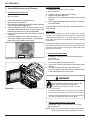
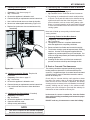
H. Convection Blower Replacement
1. Follow the proper shut down procedures.
2. Remove the left side panel by loosening the 2 screws
using a phillips head screw driver or wrench. Figure 21.1
3.
Remove two lower sheet metal screws from the back
panel to allow more clearance.
4. Disconnect the wire terminals.
5. Reach behind the blower and release the latch by pushing
the top of the latch towards the blower. Figure 21.1
6. Rock the top of the blower slightly and lift up. The blower
will pass out the left side of the appliance.
Note: You may need to loosen the surround to move it out
of the way.
7. Install replacement blower by placing the bottom flange
into the opening first then rotate blower up into position.
8. When the blower is properly positioned the latch will engage
the notch to hold the blower in place. Figure 21.1
9. Re-connect wire terminals to the new blower.
10. Reposition and Re-secure the back panel.
Note: Make sure wires are connected prior to restarting the
appliance. Failure to do so will result in the (side-mounted)
safety thermal snap disc tripping resulting in cutting power to
the appliance feed system.
Figure 21.1
June 19, 2014
7080-132C
21
MT. VERNON E2
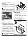
I . Combustion/Exhaust Blower Replacement
1. Follow the proper shut down procedures.
2. Remove the right side panel by loosening the 2 screws
using a Phillips head screw driver or wrench. Figure
22.1.
3. It is not necessary or recommended to remove the housing to replace or service the combustion blower. You
only need to remove the motor and impeller.
4. Disconnect the wire from the control board connection
and hall effect switch/housing.
5. Using an 7mm socket wrench or nut driver, loosen the
nuts securing the motor and impeller to the housing.
6. Holding the motor, rotate the mounting plate counter-clockwise and remove motor and impeller.
7. If the gasket between housing and motor is damaged it
will have to be replaced. A gasket is included with the
replacement blower.
8. Re-install in reverse order.
Figure 22.1
22
7080-132C
June 19, 2014
MT. VERNON E2
4
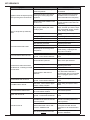
Troubleshooting Guide
With proper installation, operation, and maintenance your appliance will provide years of trouble-free service. If you do experience a problem, this troubleshooting guide will assist a qualified service person in the diagnosis of a problem and the corrective action to be taken.
This troubleshooting guide can only be used by a qualified service technician.
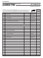
Symptom
Possible Cause
No Power to outlet.
Plug in appliance - No
response.
5 amp fuse blown
Snap disc tripped or defective.
No Fuel
Vacuum switch not closing; no vacuum
Hopper lid open
Defective hopper switch.
Unit will not light
Safety snap disc is tripped
Feed System is jammed
Feed motor not plugged in
Igniter not plugged in
Defective igniter
Firepot plugged-up / dirty
Remote receiver is set to “OFF”
Dial control is set to “OFF”
Dirty firepot, exhaust path, and/or
venting plugged
Fire starts but goes out
Exhaust sensor cannot read temperature or is loose
Exhaust plenum is dirty
Exhaust probe is defective (error
code may result)
June 19, 2014
7080-132C
Corrective Action
Check circuit breaker at service
panel.
Replace control board - don’t replace
fuse
Reset or replace snap disc.
Check hopper; load with wood
pellets
Check vacuum switch wires are
installed
Check vacuum hose is connected to
switch and feed tube port and is in
good condition
Make sure venting system is clean
Make sure front door is closed
Check vacuum tube for blockage or
restrictions/kink
Close hopper lid
Check hopper switch operation
Check hopper switch wires for
integrity
Check to make sure convection
blower wires are connected and
reset snap disc (located on RH side
of appliance)
Clean & inspect convection blower
and convection air path.
Inspect and un-jam the feed assembly
Reconnect feed motor
Connect the igniter wires
Replace igniter
Clean firepot and movable floor
Remove ash from the ashpan
Set the three-way-switch to
“REMOTE”
Turn dial control (on the appliance)
to a setting other than OFF
Clean firepot and movable floor
Inspect and clean exhaust path and
venting
Clean firebox, exhaust path, and
venting (including behind baffle)
Secure the exhaust probe to exhaust
blower housing – keeping its wire
away from hot surfaces
Clean exhaust path to plenum
Check for probe wire integrity and/
or replace defective exhaust probe
securing the exhaust probe to
exhaust blower housing – keeping its
wire away from hot surfaces
23
MT. VERNON E2
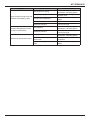
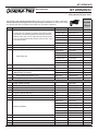
Symptom
Appliance starts and stops frequently
when operating in the remote mode
Slow or smoky start-up and/or lazy
flame
Possible Cause
Corrective Action
Area where the thermostat is placed
affects temperature.
Check thermostat proximity to doors
and windows
Thermostat located in tight spaces
effecting the on/off cycling of the
appliance.
Inspect remote thermostat location
and make sure it is not close to a
surface that heats and cools quickly.
Remote thermostat SWING function
is set too low
Raise the thermostat swing temperature (see remote function section for
instructions)
Dirty firepot, exhaust path, and/or
venting system.
Clean entire appliance including:
firepot, ash build up in firebox, firepot
area, behind baffle, firebox, exhaust
blower, venting, and ashpan.
Control board is defective.
Wire short between blower and
ground - Control board is defective
Adjust the trim (see trim adjustment
section)
Center the igniter in the chamber
Replace wood pellet fuel
Clean and un-jam the blower
Connect the blower wires to its
respective power wires
Replace blower
Secure the exhaust probe to exhaust
blower housing – keeping its wire
away from hot surfaces
Replace control board
Repair wire and replace control
board
Exhaust blower is jammed
Clean, and un-jam the blower
Not enough combustion air
Misaligned igniter
Wet fuel or poor quality fuel
Convection Blower is jammed
Not electrically connected
Convection blower fails to start
Blower is defective
Exhaust probe not sensing correct
temperature
Convection Blower fails to shut off
Exhaust blower fails to start and/or
red flashes 6X – indicating a exhaust
encoder alarm.
Not electrically connected
Blower is defective
Control board or dial control is
defective.
Exhaust Blower fails to shut off
Feed Motor fails to shut off
Convection Blower makes noise
Igniter does not turn off
Unit fails to shut off
24
Wire short between blower and
ground - Control board is defective
Wire short between ground and:
feed motor, vacuum switch, hopper
switch, or safety snap disc
Control board is defective
Convection blower is dirty causing
an out-of-balance condition
Connect the blower wires to its
respective power wires
Replace blower
Unplug dial control, if exhaust blower
runs, dial control is defective. If
exhaust blower does not run with dial
control unplugged, replace control
board.
Repair wire and replace control
board
Repair wire(s) and replace control
board
Replace control board
Clean blower impellers
Wire short between igniter and
ground – Control board is defective
Repair wire and replace control
board
Thermostat, while operating in
THERMO mode, does not meet set
point temperature
Reduce thermostat set point temperature to something less than its
local temperature
Remote thermostat is set to “ON” –
not set in THERMO mode
Set the thermostat to THERMO and
its set point lower than the local
temperature or set the thermostat to
“OFF”
The remote receiver is set to “ON”
Set the three-way-switch on the
receiver to “REMOTE”
7080-132C
June 19, 2014
MT. VERNON E2
Symptom
Possible Cause
Dirty appliance or venting
Poor fuel quality, high ash content.
Large, lazy flame (orange color) with
black ash / soot buildup on glass
Incorrect air-fuel adjustment
Excessive feeding
Feed Motor locked on
Excessive fuel spilling over the firepot and/or excessive flame
Dirty Appliance
Feed Motor locked on
Dirty Appliance
Black soot on the side of the house
June 19, 2014
Exhaust termination cap too close to
the structure
Excessive feeding (incorrect air-fuel
ratio)
7080-132C
Corrective Action
Clean unit including the firepot,
exhaust path, and venting system
Purge old fuel and use higher quality
/ or brand of fuel
Adjust the trim (see trim adjustment
section)
Adjust trim per trim dial instructions
Follow corrective action for feed
motor not turning off
Clean unit including the firepot,
exhaust path, and venting system
Follow corrective action for feed
motor not turning off
Clean unit including the firepot,
exhaust path, and venting system
Extend the termination further from
the structure
Adjust the trim (see trim adjustment
section)
25
MT. VERNON E2
Following correction of any Alarm, turn the dial control to the OFF position, wait 10 seconds and turn back to
desired setting OR unplug the unit, wait 10 seconds then restore power.
Alarm
(LED Flashing RED)
1 Red Flash: Empty Hopper Alarm
2 Red Flashes: Exhaust Probe Fail
Possible Cause
Hopper empty
Fill the hopper
Auger jam
Inspect the feed tube for jams
Vacuum switch not closing
Make sure firebox door is shut,
vacuum hose is connected to switch
and drop tube, wire connectors are
connected to vacuum switch, control
board, hopper switch, and safety
snap disc.
Hopper lid open
Close the hopper lid
Exhaust probe does not sense temperature
Secure the exhaust probe keeping
its wire away from hot surfaces and
clean the exhaust plenum
Snap disc tripped
Reset snap disc
Exhaust probe not attached to
exhaust blower properly
Secure exhaust probe to exhaust
blower housing – keeping its wire
away from hot surfaces
Exhaust path is dirty
Clean unit including the firepot,
exhaust path, and venting system
Not connected to the control board
Connect terminal end to control board
Failed component
Replace exhaust probe – securing it
to exhaust blower housing – keeping
wire away from hot surfaces
Hopper empty
Feed motor doesn’t turn
4 Red Flashes: Missed Ignition
Dirty appliance
Igniter has no power or is defective
Exhaust probe not properly installed
Igniter chamber plugged with debris
6 Red Flashes: Exhaust Blower
Alarm
Wire from exhaust blower or encoder
is disconnected or shorted
Defective exhaust blower
Defective encoder (on end of
exhaust blower)
Feed Motor Locked On
8 Red Flashes: Exhaust Over-Temp
Non-approved fuel used
Convection blower dirty
26
Corrective Action
7080-132C
Fill the hopper
Inspect feed motor circuit (hopper lid
must be closed, vacuum switch must
be closed, snap disc closed, and feed
motor must be plugged in)
Clear jam in feed tube
Clean unit including the firepot,
exhaust path, and venting system
Check igniter lead connections or
replace igniter
Secure exhaust probe to exhaust
blower housing – keeping its wire
away from hot surfaces
Clean igniter chamber
Make sure wire is not damaged /
melted and ends are fully connected
to the encoder and control board.
Replace exhaust blower
Replace exhaust blower
Repair wire(s) and replace control
board
Only use wood pellet fuel. Do not
enhance its performance with any
other combustible substance.
Clean impellers
June 19, 2014
MT. VERNON E2
Reference Materials
A. Component Functions
When describing the location of a component, it is
always AS YOU FACE THE FRONT OF THE APPLIANCE.
1. Exhaust Blower
The combustion (exhaust) blower is mounted in the bottom right
rear of appliance. The blower is designed to pull the exhaust
from the appliance and push it out through the venting system.
2. Control Board
The control board is located on the right side of appliance. It
controls the functioning of the appliance and communicates
with the dial control. The control board can only be replaced
by an authorized dealer.
3. Convection Blower
The convection blower is mounted at the bottom left of the
appliance. The convection blower pushes heated air through
the heat exchange system into the room.
4. Feed System
The feed system is located on the right side of the appliance and
can be removed as an entire assembly. The hollow feed spring
(auger) pulls pellets up the feed tube from the hopper area and
drops them down the feed chute into the firepot. Reference the
parts list for individual parts in feed assembly .
5. Firepot
The firepot is made of high quality ductile iron. The floor of
the firepot opens for cleaning and is manually operated by the
homeowner. The floor needs to return to a completely closed
position or the appliance will not operate properly.
6. Fuse
The control board fuse will blow should a short occur. The control board will need to be replaced. DO NOT REPLACE THE
FUSE. If the control board fuse blows its TRIAC, that portion
of the circuit, will remain closed causing the motor on that leg
to run continuously at high speed.
7. Heat Exchanger
The heat exchanger is located behind the baffle and transfers
heat from the exhaust system into the convection air chamber.
Remove the cast iron baffle to access the heat exchanger.
8. Hopper Lid Switch
The hopper lid switch is located on the right side, inside the
hopper. It switches the feed motor off if the hopper lid is open.
9. Igniter (Heating Element)
The igniter is mounted on the base of the firepot. Combustion
air travels over the red hot igniter creating super heated air that
ignites the pellets.
10. Power Receptacle
The power receptacle is located below the control box on
right side. Install the power cord (supplied in the appliance component pack) to the appliance receptacle. Prior
to installing, check the wall receptacle for 120 volt, 60 Hz
(standard current). Make sure the outlet is grounded and has
the correct polarity. A good quality surge protector is highly
recommended to protect the appliance electronics.
11. Overheat Snap Discs
There are two overheat snap discs located within the electro-mechanical cavity of the appliance. One is mounted on the
back of the drop tube in the center of the appliance; the other
is mounted in the RH side between the firebox and cast side
panel. Both snap discs have a reset button. If the fire tries to
June 19, 2014
burn back into the feed system, the drop tube snap disc will
shut the appliance down. If there is not enough circulation
from the convection blower the second snap disc will shut
the feed system off. Either sensor must be manually re-set
if tripped. Disconnect power before resetting.
12. Exhaust Probe - Exhaust Blower
The exhaust probe is a temperature-sensing device attached
to the exhaust blower housing via screw and clamp. It provides sympathetic exhaust temperature feedback to the control
board. In turn, the control board uses this information to adjust
its heat-output systems for best performance.
13. Vacuum Switch
The vacuum switch is located on the right side of the appliance
under the feed motor, behind right side panel. Its vacuum hose
connects to the drop tube. This switch turns the feed system
on when vacuum is present in the firebox. The vacuum switch
is a safety device to shut off the feed motor if the exhaust or
the heat exchanger system is dirty, plugged, or if the firebox
door is open.
14. Remote Thermostat
Refer to Thermostat Instructions on page 12.
15. Wiring Schematic for Control Board (below)
IGNITER
FEED MOTOR
M
VACUUM HOPPER
SWITCH SWITCH
EXHAUST
BLOWER
M
CONVECTION
BLOWER
M
SNAP
DISC
NEUTRAL
110 V
LINE
SNAP
DISC
BLACK
WHITE
PURPLE
PURPLE
BLUE
BLUE
ORANGE
WHITE
BLACK
BLACK
5
FUSE
EXHAUST
TEMPERATURE
SERIAL PORT
(SERVICE ONLY)
THERMOSTAT VCC
THERMOSTAT GND
THERMOSTAT SIG
POT SET TEMP VCC
POT SET TEMP GND
POT SET TEMP SIG
POT FEED ADJUST VCC
POT FEED ADJUST GND
POT FEED ADJUTS SIG
LED RED
LED AMBER
LED GREEN
SPEED SENSOR
Figure 27.1 - Control Board Schematic
7080-132C
27
MT. VERNON E2
B. Exploded Drawings
R
MT VERNON E2
Service Parts
Beginning Manufacturing Date: Feb 2014
Ending Manufacturing Date: Active
Pellet Stove
MTV-E2-CSB, MTV-E2-MBK, MTV-E2-PBK, MTV-E2-PDB, MTV-E2-PFT, MTV-E2-PMH
5
4
1
2
36
3
6
35
34
37
33
22
31
7
32
30
8
9
29
28
27
10
11
12
22
13
21
24
25
23
14
26
20
6
15
19
16
18
17
Part number list on following page.
03/14
28
7080-132C
June 19, 2014
MT. VERNON E2
C. Parts List
R
MT VERNON E2
Service Parts
Beginning Manufacturing Date: Feb 2014
Ending Manufacturing Date: Active
IMPORTANT: THIS IS DATED INFORMATION. Parts must be ordered from a dealer or
distributor. Hearth and Home Technologies does not sell directly to consumers.
Provide model number and serial number when requesting service parts from your dealer or
distributor.
ITEM
1
DESCRIPTION
COMMENTS
Hopper Lid
Gasket, Hopper Lid
2
3
4
5
6
Stocked
at Depot
PART NUMBER
Matte Black
7034-157MBK
Porcelian Black
7034-157PBK
Porcelian Dark Blue
7034-157PDB
Porcelian Frost
7034-157PFT
Porcelian Mahogany
7034-157PMH
Sienna Bronze
7034-157CSB
10 FT
7000-320/10
Hinge Pin
SRV7034-159
Hinge Retainer
SRV7034-163
Top
Matte Black
7034-155MBK
Porcelian Black
7034-155PBK
Porcelian Dark Blue
7034-155PDB
Porcelian Frost
7034-155PFT
Porcelian Mahogany
7034-155PMH
Sienna Bronze
7034-155CSB
Shroud Left
SRV7080-123
Side (Interchangeable)
Matte Black
7005-107MBK
Porcelian Black
7005-107PBK
Porcelian Dark Blue
7005-107PDB
Porcelian Frost
7005-107PFT
Porcelian Mahogany
7005-107PMH
Sienna Bronze
7005-107CSB
7
Side Mount Left
7034-128
8
Hinge Male
7034-138
9
Gasket, Door Rope
SRV7034-177
10
Latch, Baffle
7034-149
11
Baffle
SRV7034-263
June 19, 2014
7080-132C
Y
Y
29
MT. VERNON E2
R
MT VERNON E2
Service Parts
Beginning Manufacturing Date: Feb 2014
Ending Manufacturing Date: Active
#12 Door Assembly
12.1
12.2
12.3
12.4
IMPORTANT: THIS IS DATED INFORMATION. Parts must be ordered from a dealer or
distributor. Hearth and Home Technologies does not sell directly to consumers.
Stocked
at Depot
Provide model number and serial number when requesting service parts from your dealer or
distributor.
ITEM
12
DESCRIPTION
COMMENTS
Door Assembly
PART NUMBER
SRV7080-015
12.1
Glass Retainer
7034-136
Y
12.2
Glass Assenbly w/Gasket
7034-007
Y
Gasket, Channel 1/8 x 1-1/4 x 10
7000-377/10
12.3
Hinge Female
450-2910
12.4
Door Latch Assembly
413-5200
13
14
15
30
Front, Face
Door Left
Ash Lip
7080-132C
Matte Black
7005-108MBK
Porcelian Black
7005-108PBK
Porcelian Dark Blue
7005-108PDB
Porcelian Frost
7005-108PFT
Porcelian Mahogany
7005-108PMH
Sienna Bronze
7005-108CSB
Matte Black
7005-110MBK
Porcelian Black
7005-110PBK
Porcelian Dark Blue
7005-110PDB
Porcelian Frost
7005-110PFT
Porcelian Mahogany
7005-110PMH
Sienna Bronze
7005-110CSB
Matte Black
7080-140MBK
Porcelian Black
7080-140PBK
Porcelian Dark Blue
7080-140PDB
Porcelian Frost
7080-140PFT
Porcelian Mahogany
7080-140PMH
Sienna Bronze
7080-140CSB
June 19, 2014
MT. VERNON E2
R
MT VERNON E2
Service Parts
Beginning Manufacturing Date: Feb 2014
Ending Manufacturing Date: Active
IMPORTANT: THIS IS DATED INFORMATION. Parts must be ordered from a dealer or
distributor. Hearth and Home Technologies does not sell directly to consumers.
Stocked
at Depot
Provide model number and serial number when requesting service parts from your dealer or
distributor.
ITEM
16
DESCRIPTION
COMMENTS
Door Right
PART NUMBER
Matte Black
7005-109MBK
Porcelian Black
7005-109PBK
Porcelian Dark Blue
7005-109PDB
Porcelian Frost
7005-109PFT
Porcelian Mahogany
7005-109PMH
Sienna Bronze
7005-109CSB
17
Ash Pan Door
7034-133
18
Ash Pan Assembly
SRV7034-069
Twin Ball catch
SRV7000-532
Y
7034-224
Y
19
Intake Shield
#20 Firepot Riser Assembly
20.1
20.2
20.8
20.3
20.4
20.7
20
20.6
20.5
Firepot Riser Assembly
SRV7080-002
20.1
Firepot Assembly
SRV7034-072B
Y
20.2
Gasket, Firepot
7034-190
Y
20.3
Spring
7000-513/4
Y
20.4
Rail, Auto-clean
SRV7034-152
Y
20.5
Hitch Pin Clip, 3/32
7000-374/10
Y
20.6
Plow Weldment, Auto clean
7034-024
Y
20.7
Firepot Bottom
7034-153
Y
Firepot Floor Lever Assembly
SRV7080-018
20.8
Pkg of 4
Pkg of 10
21
Gasket, Rope, Ash Door
SRV7034-178
Y
22
Snap Disc, L250F manual Reset
SRV230-1290
Y
23
Latch Bracket Assembly
7034-049
Y
June 19, 2014
7080-132C
31
MT. VERNON E2
R
MT VERNON E2
Service Parts
Beginning Manufacturing Date: Feb 2014
Ending Manufacturing Date: Active
IMPORTANT: THIS IS DATED INFORMATION. Parts must be ordered from a dealer or
distributor. Hearth and Home Technologies does not sell directly to consumers. Provide
model number and serial number when requesting service parts from your dealer or distributor.
ITEM
DESCRIPTION
24
COMMENTS
Vacuum Switch
Vacumm Hose
25
3 Ft cut to fit
Control Board
Wire Harness
Stocked
at Depot
PART NUMBER
SRV7000-531
Y
SRV7000-373
Y
SRV7080-050
Y
SRV7080-129
Y
26
Side Mount, Right
7034-126
27
Shroud Right
SRV7080-122
28
Control Panel Assembly w/Wire Harness
SRV7080-036
29
Control Panel Door Assembly w/Control Panel Assembly
SRV7080-037
30
Combustion Blower
SRV7080-106
Y
Combustion Blower Gasket, Between Housing and Stove
SRV7080-117
Y
Combustion Blower Motor Gasket, Between Motor and Housing
SRV7080-107
Y
SRV7080-109
Y
SRV7080-108
Y
31
Wireless Thermostat Receiver
Wireless Thermostat
Y
32
Flue Collar Assembly
SRV7080-013
33
Exhaust Transition Assembly
7034-139
34
Feed Assembly
SRV7080-010
Y
Feed Spring Assembly (Only)
SRV7001-046
Y
Gasket, Feed Motor
7034-144
Feed Motor
812-4421
Y
35
Elbow Catch
7000-393
36
Convection Blower
SRV7080-105
Y
37
Magnetic Switch
7000-375
Y
Addi
32 i
l
i
b
f ll
i
7080-132C
June 19, 2014
MT. VERNON E2
R
MT VERNON E2
Service Parts
Beginning Manufacturing Date: Feb 2014
Ending Manufacturing Date: Active
IMPORTANT: THIS IS DATED INFORMATION. Parts must be ordered from a dealer or distributor.
Hearth and Home Technologies does not sell directly to consumers. Provide model number
and serial number when requesting service parts from your dealer or distributor.
ITEM
DESCRIPTION
COMMENTS
Matte Black
Porcelian Black
Component Pack Assembly (Includes Owners Manual, Quick
Start Guide, Heat Exchange & Exhaust Cleaning Instructions,
Porcelian Dark Blue
Warranty Card, Dvd “How To”, Wall Control & Harness, Power
Porcelian Frost
Cord, (4) Leveling Nuts & Bolts, Firepot Clean-Out Tool, TouchUp Paint and Label
Porcelian Mahogany
Sienna Bronze
Cleanout Tool
Stocked
at Depot
PART NUMBER
SRV7080-040
SRV7080-043
SRV7080-044
SRV7080-045
SRV7080-042
SRV7080-041
414-1140
Leveling Assembly
Y
7000-000
Paint Touch-Up
Matte Black
812-0910
Porcelian Black
1-00-0022
Porcelian Dark Blue
1-00-0020
Porcelian Frost
Porcelian Mahogany
Sienna Bronze
Power Cord
1-00-0021
855-1450
TOUCHUP-CSB
812-1180
Exhaust Probe
Y
SRV7000-669
Heating Element Assembly 18”, 120 VAC, 300 Watt,
(Wood Pellet Fuel Only)
Wing Thumb Screw 8-32 X 1/2
Wire Clip
SRV7000-647
Y
Pkg of 10
SRV7000-647/10
Y
Pkg of 24
7000-223/24
Y
Pkg of 10
7000-400/10
Y
ACCESSORIES
Collar, Offset, Top Vent
812-3570
Damper, 3 Inch - Tall Vertical Installs Only
PEL-DAMP3
Damper, 4 Inch - Tall Vertical Installs Only
PEL-DAMP4
Firescreen
SCR-7005
Log Set, (Sold as Set only)
2 Pc
LOGS-60-AE-B
Outside Air Kit
OAK-3
Top Vent Adapter
TPVNT-3
Matte Black
844-9780
Porcelian Black
WSLG-PBK
Porcelian Dark Blue
Warming Shelves
Porcelian Frost
Porcelian Mahogany
Sienna Bronze
June 19, 2014
7080-132C
Y
WSLG-PDB
WSLG-PFT
844-9810
WSLG-CSB
33
MT. VERNON E2
34
7080-132C
June 19, 2014
MT. VERNON E2
June 19, 2014
7080-132C
35
CONTACT INFORMATION
Hearth & Home Technologies
1445 North Highway
Colville, WA 99114
Division of HNI INDUSTRIES
Please contact your Quadra-Fire dealer with any questions or concerns.
For the number of your nearest Quadra-Fire dealer
log onto www.quadrafire.com
CAUTION
DO NOT DISCARD THIS MANUAL
• Important operating and • Read, understand and
follow these instrucmaintenance instructions for safe installations included.
tion and operation.
• Leave this manual with
party responsible for use
and operation.
D
DI O N
SC O
AR T
D
We recommend that you record the following pertinent
information for your heating appliance.
Date purchased/installed:
Serial Number:
Location on appliance:
Dealership purchased from:
Dealer phone:
Notes:
This product may be covered by one or more of the following patents: (United States) 5341794, 5263471, 6688302, 7216645, 7047962
or other U.S. and foreign patents pending.
36
7080-132C
June 19, 2014